
MSW 9000 - Monitor RCF - Free user manual and instructions
Find the device manual for free MSW 9000 RCF in PDF.


| Product Type | Monitoring Software for Voice Evacuation Systems |
| Brand | RCF |
| Model | MSW 9000 |
| Category | Monitor (Software) |
| Compatible Hardware | DXT9000 System (Master Unit MU 9186R) |
| Main Functions | Real-time system monitoring, SMS notification management, BMS interface via HTTP |
| Monitoring Interface | Web-based Dashboard with real-time alerts, faults, and event logs |
| SMS Notification Service | Uses Nexmo service; requires Nexmo account, credit, and internet access |
| Multi-Master Support | Up to 8 Master Units on same LAN; automatic integration |
| Default IP Address | 192.168.10.86 (standalone); range .86-.93 for multi-master |
| Languages | English, Italian (selectable in web interface) |
| Log Download | Yes, via Details page |
| Fault Reset | Manual via Clear Fault Indications (does not affect local panels) |
| Power Supply | Powered via connected Master Unit (PoE or local power supply) |
| Dimensions (Software) | N/A (software, no physical dimensions) |
| Weight | N/A |
| Maintenance & Cleaning | No physical cleaning required; keep software updated via system updates |
| Safety Precautions | Ensure network security; restrict access to authorized personnel only |
| Spare Parts & Repair | Software updates and support from RCF; no physical parts |
| General Information | Designed for professional voice evacuation systems; license required for full features |
Frequently Asked Questions - MSW 9000 RCF
User questions about MSW 9000 RCF
0 question about this device. Answer the ones you know or ask your own.
Ask a new question about this device
Download the instructions for your Monitor in PDF format for free! Find your manual MSW 9000 - RCF and take your electronic device back in hand. On this page are published all the documents necessary for the use of your device. MSW 9000 by RCF.
USER MANUAL MSW 9000 RCF
Figura 2 - Details
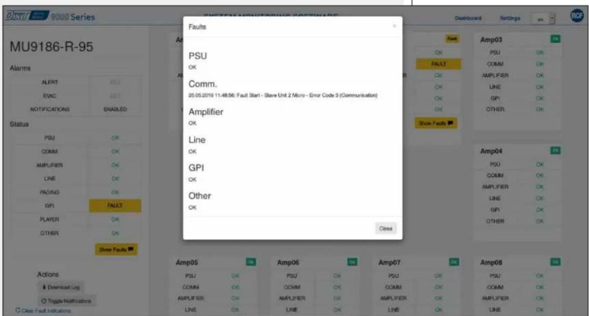
Figura 3 - Show Faults
PAGINA SETTINGS
Figura 4 - Settings
Figura 5 – Nexmo Credentials
MSW9000 is a software for DXT9000 system that offers the following features:
1. System monitoring web interface
Connecting thorough a web browser to the IP address of a stand alone Master Unit (default address http://192.168.10.86) or any Master Unit part of a multi-master system, users can access system's real-time monitoring interface in terms of:
- Alert/evacuation events in progress;
• Active faults on each unit, grouped by categories.
The main screen (Dashboard), presents a synthetic view of each Master Unit in the system, and offers the possibility to access each specific section (Details), with all sub-system detailed information. From the Details page, users can also download the log of events and faults.
2. SMS notification manager
MSW9000 allows to send SMS with system's events information to one or more mobile numbers, using the external service Nexmo. To use this feature users need:
• to create a Nexmo customer account (https://www.nexmo.com/), and manage the related phone credit;
• to charge the phone credit. Without credit, it will be possible to send a limited number of SMS per week to a limited number of contacts;
• to inserting Nexmo credentials in the software Settings section;
• to add one or more phone numbers in the software Contacts section;
• to provide an internet access to the Master Unit.
The Master Unit IP address and Gateway shall be set in the DXT9000CC configurator.
Notification Manager is subject to the same license that enables the web interface.
STAND ALONE SYSTEMS
DASHBOARD PAGE
In a single Master Unit system, the features available are (upon purchase of the license):
• real-time monitoring system's web interface;
- SMS notification service.
The interface with BMS over HTTP protocol is also available, without the need to purchase the license.
Users can then access the web interface via browser, using the default address http://192.168.10.86.
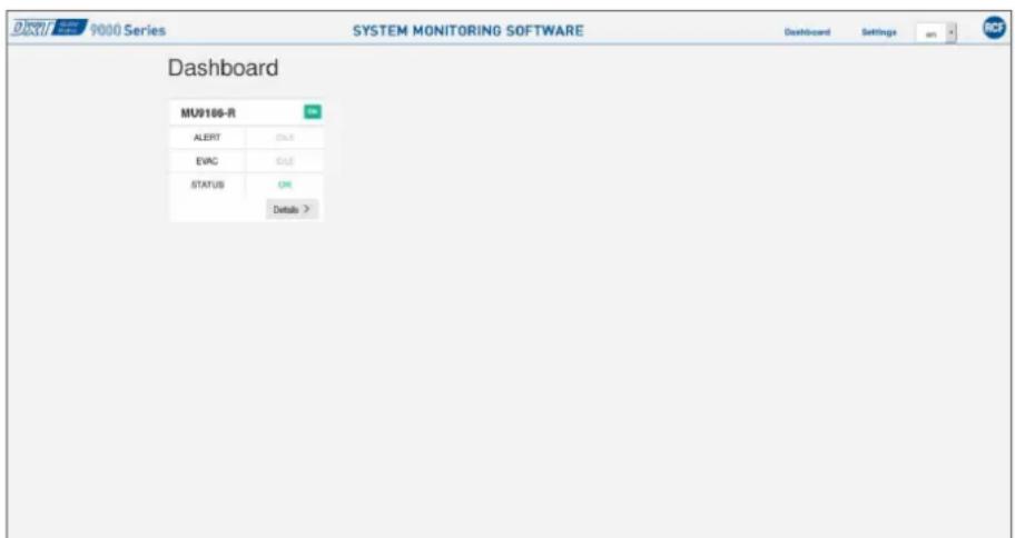
Figure 1 - Dashboard
DETAILS PAGE
For a single Master Unit system information are accessible in the Details section containing events/faults grouped by Slave Units and category.
Both the Dashboard and Details pages are updated in real-time depending on the occurrence of failures or alert/evacuation events.
Users can also change the language from English to Italian using the selection box in the upper-right page angle (en/it).
In case of failure, it is possible to open a descriptive pop-up via button Show Faults, showing the detail of the specific fault.
The Download Log button allows to download on a local PC the system log.
The Toggle Notifications function enable/disable SMS notifications (if previously configured), and is extremely useful during configuration, maintenance or calibration activities, when failures are intentionally generated to specific check system's functions.
Clear Fault Indications, finally, allows a manual reset of faults on the web interface, functionality useful in case of pages refresh or communication problems. However, Clear Fault Indications do not act on units fault indications reported on local panels.
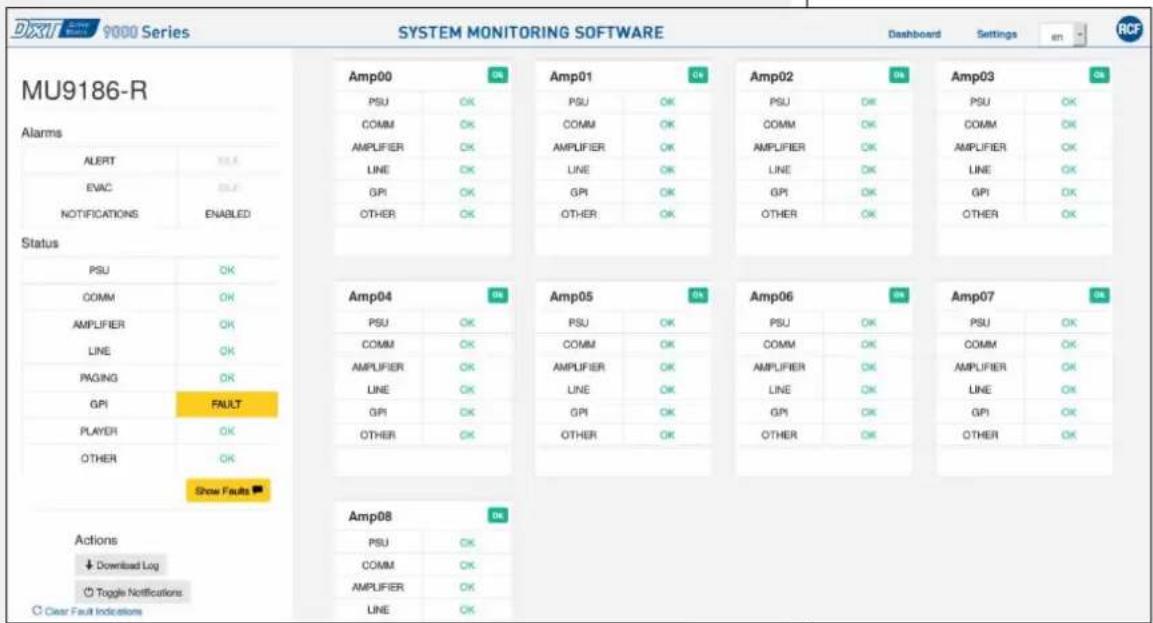
Figure 2 - Details
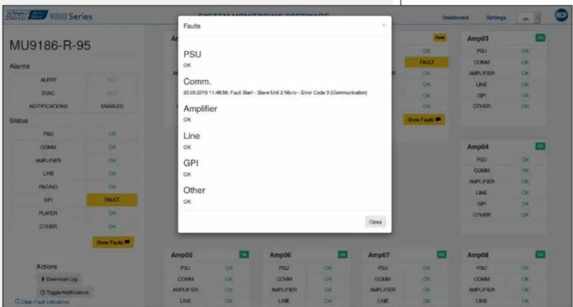
Figure 3 - Show Faults
SETTINGS PAGE
In the Settings page users you can access Nexmo setup pages (credentials and phone numbers for SMS notification).
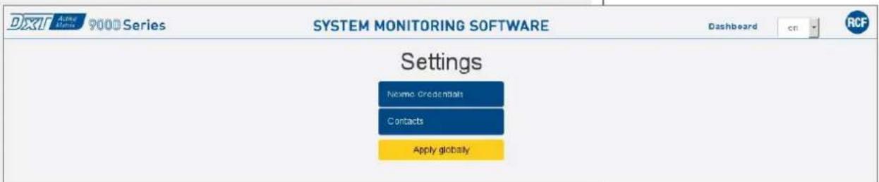
Figure 4 - Settings
Within the Nexmo settings following information shall be configured:
- Sender: name that will appear as SMS notification sender, and it will the same for all monitored systems;
- Access Key ID and Secret Access Key: credentials provided during customer Nexmo registration.
It is also possible to send test SMS to a specific number using the Number field and clicking Test. This operation is available only with credit charged on customer account.
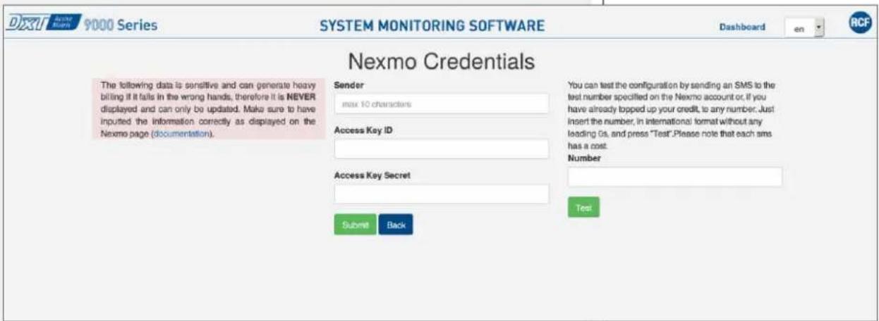
Figure 5 – Nexmo Credentials
In the Contacts section, users can add and remove phone numbers using Add and Delete buttons. The Apply Globally button is used only in multi-master mode (see multi-master systems paragraph).
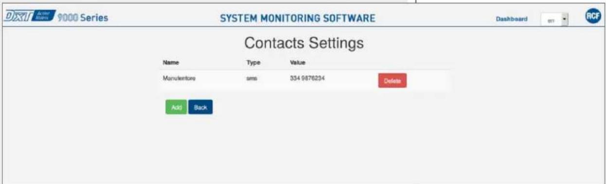
Figure 6 – Contacts
MULTI-MASTER SYSTEMS
Each MU 9186R is already configured for use on multi-master systems. The connection between systems is automatically made following the steps below:
- assign different IP to each Master Unit, included in the range 192.168.10.86 and 192.168.10.93 (up to a maximum of 8 Master Unit);
- Connection of all Master Units on the same LAN.
No additional specific configuration is required, besides the usual one of individual subsystems via DXT9000CC. New subsystems can be added to an existing multi-master system simply assigning them an IP not used in the range between .86 and .93 and connecting it in the network.
From the web interface of any of the Master Unit of a multi-master system it is possible to monitor the whole system.
The configuration of SMS notifications, if enabled, is set for the whole system in the web interface by connecting to any Master Unit, performing the configuration and then clicking the Apply Globally button.
The interface with BMS is individual for each Master Unit belonging to the multi-master system.
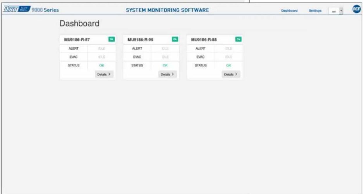
Figure 7 – Dashboard on multi-master system
RCF S.p.A.



Brand : RCF
Model : MSW 9000
Category : Monitor