
HDMX44A-18G - Router KanexPro - Free user manual and instructions
Find the device manual for free HDMX44A-18G KanexPro in PDF.


| Product Type | HDMI Matrix Router |
| Model | HDMX44A-18G |
| Brand | KanexPro |
| Number of Inputs | 4 x HDMI |
| Number of Outputs | 4 x HDMI |
| Maximum Bandwidth | 18 Gbps |
| Supported Resolution | 4K@60Hz (4:4:4) |
| HDCP Version | 2.2 |
| EDID Management | Built-in EDID learning and emulation |
| Control Methods | IR remote, RS-232, front panel buttons |
| Rackmount Size | 1U |
| Dimensions (W x D x H) | 17.32 x 6.69 x 1.73 inches (440 x 170 x 44 mm) |
| Weight | 3.3 lbs (1.5 kg) |
| Power Supply | 100-240 V AC, 50/60 Hz |
| Power Consumption | 15 W (max) |
| Operating Temperature | 32°F to 104°F (0°C to 40°C) |
| Storage Temperature | -4°F to 140°F (-20°C to 60°C) |
| Maintenance | Wipe with a soft, dry cloth. Do not use liquids or solvents. |
| Safety Precautions | Do not expose to rain or moisture. Keep ventilation slots clear. |
| Spare Parts & Repairability | No user-serviceable parts. Contact KanexPro support for repairs. |
Frequently Asked Questions - HDMX44A-18G KanexPro
User questions about HDMX44A-18G KanexPro
0 question about this device. Answer the ones you know or ask your own.
Ask a new question about this device
Download the instructions for your Router in PDF format for free! Find your manual HDMX44A-18G - KanexPro and take your electronic device back in hand. On this page are published all the documents necessary for the use of your device. HDMX44A-18G by KanexPro.
USER MANUAL HDMX44A-18G KanexPro
natural_image
Black HOM HOOPM device with control panel and display (no visible text or symbols on body)4K x 2K ^+
HDCP2.2
Ultra-Fast 4x4 HDMI Matrix Switcher with Audio Extraction 4K/60Hz
All Right Reserved
MPN: HDMX44A-18G
SAFETY PRECAUTIONS
Please read all instructions before attempting to unpack, install or operate this equipment and before connecting the power supply. Please keep the following in mind as you unpack and install this equipment:
• Always follow basic safety precautions to reduce the risk of fire,
• electrical shock and injury to persons.
• To prevent fire or shock hazard, do not expose the unit to rain, moisture
• or install this product near water.
- Never spill liquid of any kind on or into this product.
- Never push an object of any kind into this product through any openings or empty slots in the unit, as you may damage parts inside the unit.
- Do not attach the power supply cabling to building surfaces.
- Use only the supplied power supply unit (PSU). Do not use the PSU if it is damaged.
- Do not allow anything to rest on the power cabling or allow any weight to be placed upon it or any person walk on it.
- To protect the unit from overheating, do not block any vents or openings in the unit housing that provide ventilation and allow for sufficient space for air to circulate around the unit.
- Please completely disconnect the power when the unit is not in use to avoid wasting electricity.
TRADEMARK ACKNOWLEDGMENTS
All products or service names mentioned in this document are trademarks of the companies with which they are associated.
INTRODUCTION
- Introduction......4
- Applications....4
- Package Contents......4
- System Requirements....4
- Features....4
- Operation Controls and Functions....5
6.1 Front Panel....5
6.2 Rear Panel....6
6.3 Remote Control....7
6.4 IR Cable Pinouts....8
6.5 RS-232 Pinout and Defaults....8
6.6 Front Panel LCD Menu....9
6.7 WebGUI Control....14
6.7.1 Video Switch Tab....16
6.7.2 EDID Settings Tab....20
6.7.3 Device Settings Tab....21
6.8 Telnet Control....22
6.9 Serial and Telnet Commands....23
- Connection Diagram....28
- Specifications....29
8.1 Technical Specifications....29
8.2 Video Specifications....29
8.3 Audio Specifications....31
8.3.1 Digital Audio....
8.3.2 Analog Audio....31
8.4 Cable Specifications....32
9. Acronyms....32
1. INTRODUCTION
The KanexPro HDMX44A-18G is a4K UHD 4x4 HDMI Matrix that provides the ability to connect up to four 4K UHD HDMI sources to up to four 4K UHD HDMI displays and freely switch between them. This unit comes with full support for 18Gbps resolutions up to and including 4K@60Hz (4:4:4, 8-bit) as well as support for 16-bit Deep Color, HDR (High Dynamic Range), HD audio and other features defined by the HDMI 2.0 specification. With a comprehensive EDID management feature that includes the ability to select between built in EDIDs, EDIDs copied from connected sink devices, as well as user provided EDIDs, this matrix can solve many interconnectivity problems. The unit's OSD has the ability to display up to 2 lines of user customized text, on top of the video displayed over each output, in the color of your choice. This unit provides an intuitive set of front panel controls with an OSD as well as RS-232, Telnet, WebGUI, and IR remote control options.
2. APPLICATIONS
• Residential or commercial AV matrix installations
• Security systems
- Lecture halls and ballrooms
• Retail product showrooms
- Control centers
3. PACKAGE CONTENTS
- 1 x UHD+ 4 x 4 HDMI Matrix with Audio Output
• 1 x 24V/2.7A DC Power Adapter
• 1 x Remote Control (CR-177)
• 1 x Rackmount Ears (Set of 2) - 1 x Shockproof Feet (Set of 4)
• 1 x Operation Manual
4. SYSTEM REQUIREMENTS
• HDMI source equipment such as media players, video game
• consoles or set-top boxes.
- HDMI receiving equipment such as HDTVs, monitors or audio amplifiers.
- The use of Premium High-Speed HDMI cables is highly recommended.
5. FEATURES
• HDMI inputs and outputs support 18Gbps 4K UHD+ with HDR signals
• DVI 1.0 compliant with the use of an HDMI to DVI adapter
• HDCP 1.x and 2.2 compliant
• HDMI inputs and outputs support UHD+ resolutions up to
• 4096 x 2160@60Hz (4:4:4, 8-bit)
• Supports 16-bit Deep Color up to 1080p60
• Supports pass-through of LPCM (up to 8 channels), bitstream and HD bitstream audio formats
- High-quality DAC (Digital to Analog audio Conversion) with local analog stereo audio breakout for each HDMI output (LPCM 2.0 sources only)
• Supports six internal EDIDs, four external EDIDs copied from connected devices, and four user provided EDIDs
- OSD with user customizable information text
- Controllable via front-panel buttons with LCD, WebGUI, Telnet, RS-232, and IR remote
6. OPERATION CONTROLS AND FUNCTIONS
6.1 Front Panel

flowchart
graph LR
    A["Input"] --> B["1: 4x4 μ"]
    B --> C["2: with Audio"]
    C --> D["3: OUTA"]
    D --> E["4: OUTB"]
    E --> F["5: OUTC"]
    F --> G["6: OUTD"]
    G --> H["7: OUTE"]
    H --> I["8: OUTF"]
    I --> J["9: OUTG"]
    J --> K["10: OUTH"]
    K --> L["Output"]
    style A fill:#f9f,stroke:#333
    style L fill:#bbf,stroke:#333
- POWER Button: Press this button to power the unit on (green LED) or place it into stand-by mode (red LED).
- IN 1\~4 & OUT A\~D Buttons: Accepts IR signals from the included IR remote for control of this unit only.
- USB 2.0 (Type A) Ports: Press the "OUT" keys (A\~D) of the outputs you wish to route a source to (they will flash to indicate selection). Next, press the "IN" key of the input (1\~4) you wish to route to the selected outputs. Finally, press "CONFIRM" to confirm your selection and execute the routing change.
- CONFIRM Button: Press this button to confirm newly made input/output routing selections.
CANCEL Button: Press this button to cancel newly made input/output/preset routing selections before they have been confirmed. - MENU BUTTON: Press to enter the LCD menu, or to back out from menu items.
ENTER Button: Press to confirm a selection within the LCD menu or to go deeper into a menu item. - (PLUS) & - (MINUS) Buttons: Press to move up and down or adjust selections within the LCD menu.
- ALL Button: Press this button to select all outputs simultaneously for routing. Next, press the "IN" key of the input (1\~4) you wish to route to all outputs. Finally, press "CONFIRM" to confirm your selection and execute the routing change.
- PRESET Button: Press to enter the preset recall menu in the LCD window. Press the "+/-" buttons followed by the "ENTER" button to select and activate the preferred preset.
- LOCK Button: Press to lock all button functions on the front panel. Press and hold for 3 seconds to release the lock function. The LCD will display "Lock" when the function is active.
- MUTE Button: The "MUTE" button functions as a blank audio/video source. To use it, follow the standard matrix routing instructions, but use the "MUTE" button as the input to blank out the selected outputs. When a "MUTE" input is in use it will show up as "M"
within the routing display.
-
Note: The associated analog output will not be muted.
-
LCD window: Displays the unit's menu, settings and information.
6.2 Rear Panel
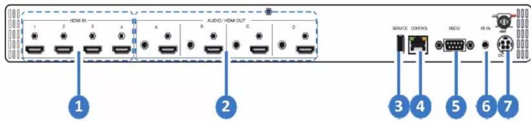
-
HDMI IN 1-4 Ports: Connect to HDMI source equipment such as media players, game consoles or set-top boxes.
-
AUDIO/HDMI OUT A\~D Ports: Connect the HDMI outputs to devices such as HDMI TVs, monitors or amplifiers for digital video and audio output. Connect the audio outputs to powered speakers or an amplifier for analog stereo audio output. The audio from each stereo analog output will be the same as the HDMI output it is paired with.
-
SERVICE Port: This slot is reserved for firmware update use only.
-
CONTROL Port: Connect directly, or through a network switch, to your PC/laptop to control the unit via Telnet/WebGUI.
-
RS232 Port: Connect directly to a PC, laptop or other serial control device to send RS-232 commands to control the unit.
-
IR IN PORT: Connect to the provided IR Extender to extend the IR control range of the unit. Ensure that the remote being used is within direct line-of-sight of the IR Extender.
-
DC 24V Port: Plug the 24V DC power adapter into the unit and connect it to an AC wall outlet for power.
6.3 Remote Control
- POWER Button: Press to power the unit on or place it into stand-by mode.
- 1/A \~ 4/D Button: Press these keys to configure the video routing. Press the "-/OUT" key followed by the key (A\~D) of the outputs you wish to route a source to (they will flash on the LCD to indicate selection). Next, press the "+/IN" key followed by the input (1\~4) you wish to route to the selected outputs. Finally, press "ENTER" to confirm your selection and execute the routing change.
Note: Buttons 5/E-8/H have no function with this matrix.
- ALL Button: Press this key to select all outputs simultaneously for routing. Next, press the key of the input (1-4) you wish to route to all outputs. Finally, press "ENTER" to confirm your selection and execute the routing change.
MUTE Button: Press this key to mute video output. Press the key of the input (1-4) you wish to route then press mute key to mute video output.
INFO Button: Switches the information displayed on each output's OSD between the user customized text and the current video/ Ethernet details.
PRESET Button: Press to enter the preset call menu in the LCD window. Press the "+/IN" and "-/OUT" buttons followed by the "ENTER" button to select and activate the preferred preset.
- MENU Button: Press to enter the LCD menu, or to back out from menu items.
ENTER Button: Press to confirm a selection within the LCD menu or to go deeper into a menu item.
CANCEL Button: Press to cancel newly made input/output/preset routing selections before they have been confirmed.
+ (PLUS)/IN Button: Press to navigate up within menus or to begin the selection of an input for routing.
- (MINUS)/OUT Button: Press to navigate down within menus or to begin the selection of outputs for routing.

6.4 IR Cable Pinout
IR Extender Cable

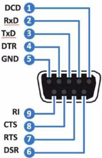
6.5 RS-232 Pinout and Defaults
| Serial Port Default Settings | |
| Baud Rate 19200 | |
| Data Bits 8 | |
| Parity Bits None | |
| Stop Bits 1 | |
| Flow Control None | |
DE-9 Female Port
6.6 Front Panel LCD Menu
All primary functions of this unit can be controlled by using the front panel LCD menu which is activated by pressing the MENU button on the front of the unit. Use the + (PLUS), - (MINUS), and ENTER buttons to navigate the LCD menu. Press the MENU button to back out from any menu item and then press it again to close the menu.
| MAIN MENU |
| EDID |
| Preset Setup |
| Network Setup |
| OSD Setup |
| CEC Send |
| Firmware |
| Firmware Update |
| Factory Reset |
The individual functions of the LCD menu will be introduced in the following section. Items marked in BOLD are the factory default settings.
| EDID | |
| 2ND LEVEL 3RD LEVEL | |
| In 1-4 01 FHD 2Ch | |
| 02 FHD MCh | |
| 03 UHD 2Ch | |
| 04 UHD MCh | |
| 05 UHD+ 2Ch | |
| 06 UHD+ MCh | |
| 07 Sink A | |
| 08 Sink B | |
| 09 Sink C | |
| 10 Sink D | |
| 11 User 1 | |
| 12 User 2 | |
| 13 User 3 | |
| 14 User 4 | |
| In All 01 FHD 2CH | |
| 02 FHD MCh | |
| 03 UHD 2Ch | |
| 04 UHD MCh | |
| 05 UHD+ 2Ch | |
| 06 UHD+ MCh | |
| 07 Sink A | |
| 08 Sink B | |
| 09 Sink C | |
| 10 Sink D | |
| 11 User 1 | |
| 12 User 2 | |
| 13 User 3 | |
| 14 User 4 | |
- In 1\~4: Select the EDID to assign to each input independently. 6 internal EDIDs, 4 sink EDIDs and 4 user EDIDs are available. Press the "Enter" button to confirm the selection. After making a selection the change will occur immediately on that input.
Note: After changing the EDID on an input, the video will typically black out briefly while the source adjusts to the new information.
- In All: Select the EDID to assign to all inputs. 6 internal EDIDs, 4 sink EDIDs and 4 user EDIDs are available. Press the "Enter" button to confirm the selection. After making a selection the change will occur immediately on all inputs.
Note: This setting will override any independently set EDID selections.
| Preset Setup | |
| 2ND LEVEL 3RD LEVEL | |
| 1~4 [Store Preset] | |
- Preset Setup: Select the number of the preset to store the current routing configuration into. Press the "Enter" button to confirm the selection. After saving the preset, the stored routing will be displayed on the LCD. Press the "Menu" button to return to normal operation.
| Network Setup | |
| 2ND LEVEL 3RD LEVEL | |
| Link: [Current Link Status] | |
| Mode: [Current Network Mode] | |
| IP: [Current IP Address] | |
| Mask: [Current Netmask] | |
| Gate: [Current Gateway Address] | |
| MAC: [MAC Address] |
- Network Status: Displays the unit's current networking information or status for each item.
| Network Setup | |
| 2ND LEVEL 3RD LEVEL | |
| Mode Static | |
| DHCP | |
| IP: [Current Static IP Address] | |
| Mask: [Current Netmask] | |
| Gate: [Current Gateway Address] | |
- Mode: Set the unit to Static or DHCP mode. When DHCP mode is selected, all IP address information will be assigned automatically by the local DHCP server. When Static is selected, the IP address, netmask and gateway must be set manually and additional menu items become available.
- IP: When DHCP is off, the IP address can be set here. Press the "Enter" button to begin editing the address and use the "+" and "-" buttons to adjust each value. Press the "Enter" button to store the current number segment and move to the next segment.
Note: The unit's default static IP address is 192.168.1.50.
- Mask: When DHCP is off, the netmask can be set here. Press the "Enter" button to begin editing the address and use the "+" and "-" buttons to adjust each value. Press the "Enter" button to store the current number segment and move to the next segment.
- Gate: When DHCP is off, the gateway address can be set here. Press the "Enter" button to begin editing the address and use the "+" and "-" buttons to adjust each value. Press the "Enter" button to store the current number segment and move to the next segment.
| OSD Setup | |
| 2ND LEVEL 3RD LEVEL | |
| Out A | OFF |
| ON | |
| Out B | OFF |
| ON | |
| Out C | OFF |
| ON | |
| Out D | OFF |
| ON | |
- Out A\~D: Enable or disable the OSD banner on each output. The change will occur after "Enter" has been pressed on a changed selection.
| CEC Send | |
| 2ND LEVEL 3RD LEVEL | |
| Out A~D ON | |
| OFF | |
| VOL+ | |
| VOL- | |
| MUTE | |
-
Out A\~D: Pick the preferred output port using the "+" and "-" buttons and then press the "Enter" button to select it. Using the "+" and "-" buttons, pick the appropriate CEC command to send to the display connected to the selected output port.
-
On/Off: Turn the connected display on or off.
- Vol +/Vol -: Increase or decrease the volume of the connected display.
- Mute: Mute the audio output of the connected display.
Note: Not all displays can support all CEC commands.
| CEC Send | |
| 2ND LEVEL 3RD LEVEL | |
| Firmware [Current firmware version] |
- Firmware: Displays the unit's current firmware version.
| Firmware Update | |
| 2ND LEVEL 3RD LEVEL | |
| Do USB Update? NO | |
| YES | |
- Do USB Update: Selecting "Yes" will prepare the unit to update firmware via the USB port. After inserting a USB thumb drive containing a valid firmware file (*.bin format) the update process will begin. After completion the unit will automatically reboot.
| Firmware Reset | |
| 2ND LEVEL 3RD LEVEL | |
| Do Factor Reset? NO | |
| YES | |
- Do Factory Reset: Selecting "Yes" will perform a factory reset and return the unit to its factory default state. After the reset is complete, the unit will reboot automatically.
6.7 WebGUI Control
• Device Discovery
Please obtain the "Device Discovery" software from your authorized dealer and save it in a directory where you can easily find it.
Connect the unit and your PC/Laptop to the same active network and execute the "Device Discovery" software. Click on "Find Devices on Network" and a list of devices connected to the local network will show up indicating their current IP address.
Note: The unit's default IP address is 192.168.1.50.

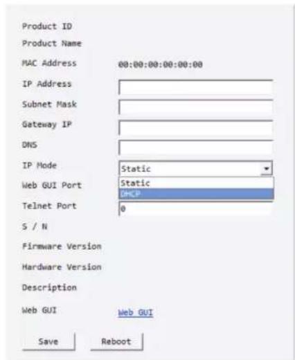
By clicking on one of the listed devices you will be presented with the network details of that particular device.
-
IP Mode: If you choose, you can alter the static IP network settings for the device, or switch the unit into DHCP mode to automatically obtain proper network settings from a local DHCP server. To switch to DHCP mode, please select DHCP from the IP mode drop-down, then click "Save" followed by "Reboot".
-
WebGUI Hotkey: Once you are satisfied with the network settings, you may use them to connect via Telnet or WebGUI. The network information window provides a convenient link to launch the WebGUI directly.
- WebGUI Overview
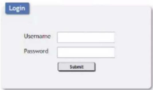
After connecting to the WebGUI's address in a web browser, the login screen will appear. Please enter the appropriate user name and password then click "Submit" to log in.
Note: The default user name and password is "admin".
On the left side of the browser you will see the following menu tabs where all primary functions of the unit are controllable via the built in WebGUI. The individual functions will be introduced in the following sections.

Clicking the red "Logout" tab will automatically log the currently connected user out of the WebGUI and return to login page.
6.7.1 Switch Tab
This page provides video routing settings, preset saving/loading, and I/O renaming options. To begin assigning a new video route, please click the button of the HDMI output you wish to send video to and then click on the button of the preferred HDMI input port. If desired, you may select more than one output prior to selecting the input. As you select each button they will change their color to orange. The new route will become active immediately after selecting the input port and the routing information displayed on the buttons will change accordingly.
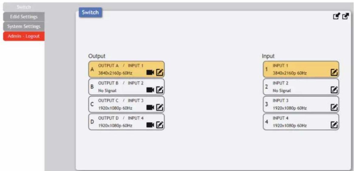
- Output: Buttons for selecting the output (A\~D) to route A/V Inputs to. Details about the output names and currently selected Input are also displayed here. Clicking on the "edit" icon (☑) opens up the Edit Output window which allows for changing a variety of settings related to the video output.
- Video Mute: Each output can be individually muted (black video, no audio). To mute an output, please click the (■) icon within the appropriate output button. To unmute the output, please click the icon a second time.
Note: The associated analog output will not be muted.
- Input: Buttons for selecting the input to route to the selected output(s). Detail about the input names and signal information is also displayed here. Clicking on the "edit" icon (☑) opens up the Edit Input window which allows for changing the input's name.
Note: Blank spaces (“”) are not allowed in names.

3) Edit Output: This window allows for changing a variety of settings related to the video output.
- Output Name: To rename the output port, type the new name in the space provided in the Edit window. Click the "Save" button to confirm the change.
Note: Blank spaces (") are not allowed in names.
- OSD: This switch enables or disables the OSD custom text display for this output.
- OSD Coordinate: This section defines the location of the OSD custom text. The X value can be from 1 to 1920 and the Y value can be from 1 to 1080. Click the "Save" button to confirm changes.
- OSD Text: Each output can display up to 2 lines of customized OSD text. Enter each line of text here. Click the "Save" button to confirm changes.
Note: Each line of text can have up to 64 characters.
- OSD Text Size: Use the dropdown to select the preferred size for the OSD custom text. Available sizes are: 1x, 2x, and 4x.
- OSD Text Color: Use the dropdown to select the preferred color for the OSD custom text. Available colors are: black, white, red, green, blue, magenta, yellow, cyan, and gray.
- OSD Background Color: Use the dropdown to select the preferred background color for the OSD custom text. Available colors are: black, white, red, green, blue, magenta, yellow, cyan, and gray.
- OSD Background Color Transparent Level: Use the dropdown to select the preferred transparency level of the OSD custom text's background. The available range is from Level 1 (fully opaque) to Level 8 (fully transparent).


4) Preset Settings: This matrix can store up to four video routing presets. Presets can be utilized to store multiple routing states in advance for rapid, hassle-free, recall.
Preset Set: Once you have the matrix set the way you like, you can click the "Preset Store" icon (☐) in the upper right corner of the window and the Preset Store window will open. Hovering the mouse over each button will display the current routing stored within it. You may also rename each preset by selecting the "Edit" icon (☑). Click the center of the preferred preset's button to store the current routing state in that preset.
Preset Recall: To load a previously stored preset, please click the "Preset Recall" icon (↗) and you will be presented with a choice of the 4 available presets. Hovering the mouse over each button will display the routing currently stored within it. The preset will activate immediately upon clicking the button.
6.7.2 EDID Settings Tab
This matrix provides the option of six standard EDIDs, four sink sourced EDIDs and four user uploaded EDIDs that can be assigned to each input port individually. The names of the four user uploaded EDIDs can changed if desired.
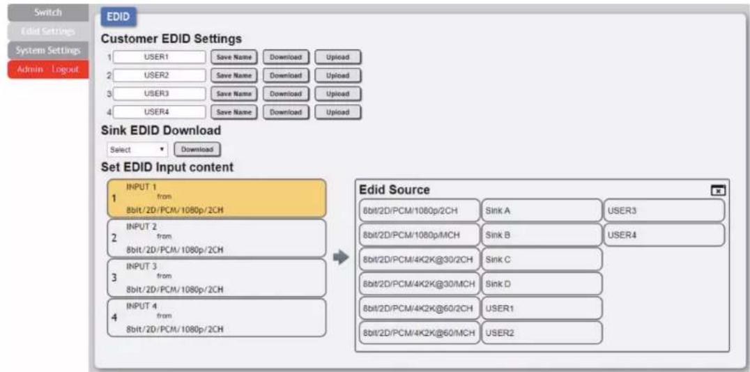
1. Customer EDID Settings:
- Save Name: To change the name of a Customer EDID, type the new name in the space provided, then click on the "Save Name" button.
- Download: To save an existing user EDID to your local PC please press the "Download" button next to the EDID you would like to save. Depending on your browser settings you will either be asked where to save the downloaded file, or the file will be transferred to the default download location on your PC.
- Upload: To upload a new user EDID, please click the "Upload" button next to the Customer EDID Settings item you would like to change. An EDID Upload window will appear, allowing you to locate and upload the preferred EDID file (*.bin format) from a local PC. Once the correct file has been selected, please click the "Upload" button in the window, and the file will be transferred to the matrix.
- Sink EDID Download: To save the EDID from one of the connected displays to your local PC, select the appropriate sink from the dropdown list then press the "Download" button. Depending on your browser settings you will either be asked where to save the downloaded file, or the file will be transferred to the default download location on your PC.
Note: In most cases, assigning a new EDID to an input will cause the affected input to briefly blink out while the source adapts to the new information.
This matrix provides the following 6 default EDIDs:
| Unit's Default EDID | |
| FHD/2CH | 1920 x 1080p@60Hz (4.95Gbps) & 8-bit color, LPCM 2.0 |
| FHD/MCH | 1920 x 1080p@60Hz (4.95Gbps) & 8-bit color, LPCM 7.1 & Bitstream |
| UHD/2CH | 3840 x 2160p@30Hz (10.2Gbps) & Deep Color (8/10/12-bit), LPCM 2.0 |
| UHD/MCH | 3840 x 2160p@30Hz (10.2Gbps) & Deep Color (8/10/12-bit), LPCM 7.1 & Bitstream |
| UHD+/2CH | 3840 x 2160p@60Hz (18Gbps) & Deep Color (8/10/12-bit), LPCM 2.0 |
| UHD+/MCH | 3840 x 2160p@60Hz (18Gbps) & Deep Color (8/10/12-bit), LPCM 7.1 & Bitstream |
Note: In some rare cases it is possible for custom or external EDIDs to cause compatibility issues with certain sources. If this happens, it is recommended to switch to one of the 6 default EDIDs for maximum compatibility.
6.7.3 System Settings Tab
This page provides system configuration options including turning the unit's power on/off, changing the network settings, resetting the system to factory defaults and updating the firmware.

- Power: Press this switch to toggle the unit's power between ON and OFF (standby mode).
Note: While in standby mode the unit's WebGUI, Telnet and RS-232 controls are still active.
- Web User Setting: This section provides a way to change the user name and password for the Administrator account. Click on "Save" to confirm and activate any changes made to these settings.
Note: The default username and password is "admin".
-
Web Login Timeout (Minute): Select the length of time to wait before logging the user out of the WebGUI due to inactivity. The available range is from 5 to 60 minutes.
-
Network: The unit's IP mode may be switched between Static IP or DHCP. In Static IP mode the IP, netmask and gateway addresses may be manually set. When in DHCP mode, the unit will attempt to connect to a local DHCP server and obtain IP, netmask and gateway addresses automatically. Press "Save" after making any changes to the IP configuration or mode.
Note: The unit's default IP address is 192.168.1.50. If the IP address is changed then the IP address required for WebGUI/Telnet access will also change accordingly.
-
Reset to Default: To reset the unit's routing selections to the default settings, click the "Routing Reset" button. To reset the unit to its factory default state press the "Fadefault" button. After the reset is complete, the unit will reboot automatically.
-
Firmware Upgrade: To update the unit's firmware, click the "Choose File" button to open the file selection window and then select the firmware update file (*.bin format) located on your local PC. After selecting the file, click the "Upgrade" button to begin the firmware update process. After the upgrade is complete, the unit will reboot automatically.
6.8 Telnet Control
Before attempting to use Telnet control, please ensure that both the unit and the PC are connected to the same active networks.
| To Access the Command Line Interface (CLI) | |
| Windows 7 | Click Start, type “cmd” in the search field, and press Enter. |
| Windows XP | Click Start > Run, type “cmd”, and press Enter. |
| Mac OS X | Click Go > Applications > Utilities > Terminal. |
Once in the Command Line Interface (CLI) type "telnet" followed by the IP address of the unit (and the port number if it is non-standard) and then hit "Enter". This will connect us to the unit we wish to control.
![Microsoft Windows [Version 6.1.7601] Copyright (c) 2009 Microsoft Corporation](/content/2026/05/1062435/images/ea39eccb50c28b2e8459373632acef702480946ce4d1fdfa4cb2c78b43ac313b.jpg)
Note 1: If the IP address is changed then the IP address required for Telnet access will also change accordingly.
Note 2: The default IP address is 192.168.1.50.
6.9 Serial and Telnet Commands
| COMMAND |
| Description and Parameters |
| HELP←Show the full command list. |
| ?←Show the full command list. |
| PO←Turn the unit off (stand-by mode). |
| P1←Turn the unit on. |
| ST←Show the unit's current firmware version and routing status. |
| FADEFAULT←Reset the unit to factory defaults. |
| REBOOT←Reboot the unit. |
| UPDATE←Prepare the unit to update firmware via the USB port. After inserting a USB thumb drive containing a valid firmware file (*.bin format) the update process will begin. After completion the unit will automatically reboot. |
| QUIT←Log out from the current Telnet session. |
| SIPMODE N1←Set the IP address assignment mode.Available values for N1:STATIC [Static IP mode]DHCP [DHCP mode] |
| SETIP N1 N2 N3←Set the IP address, netmask and gateway address to use when in Static IP mode.N1 = X.X.X.X [X = 0 ~ 255, IP address]N2 = X.X.X.X [X = 0 ~ 255, Netmask]N3 = X.X.X.X [X = 0 ~ 255, Gateway address] |
| IPCONFIG←Show the unit's current IP configuration information. |
| ETH_FADEFAULT←Reset the unit's network settings to the factory defaults. |
| NAME N1 N2←Set a name for the specified preset.N1 = 1-4 [Preset number]N2 = {Preset name} [8 characters maximum] |
| N1 N2←Route the specified input to one or more outputs.N1 = A-D [Output port letter(s)]N2 = 1-4 [Input port number]Note: Multiple output letters may be assigned to N1 to route the same source to more than one output at once. For example, "ABD2" routes input 2 to outputs A, B, and D. |
| IN1←Route the specified input to all outputs.N1 = 1-4 [Input port number]Note: For example, "13" routes input 3 to all outputs. |
| RS←Reset the unit's routing to the factory default. |
| STORE N1←Save all current routing assignments to the specified preset.N1 = 1-4 [Preset number] |
| SHOW N1←List the routing assignments stored in the specified preset.N1 = 1-4 [Preset number] |
| PRESET N1←Activate the routing assignments saved in the specified preset.N1 = 1-4 [Preset number] |
| EM N1 N2←Set the EDID to use on the specified input.N1 = 1-4 [Preset number]Available values for N2:1 [FHD 2CH]2 [FHD MCH]3 [UHD 2CH]4 [UHD MCH]5 [UHD+ 2CH]6 [UHD+ MCH]7 [Output A]8 [Output B]9 [Output C]10 [Output D]11 [User EDID 1]12 [User EDID 2]13 [User EDID 3]14 [User EDID 4] |
| USEREDID N1 N2←Set a name for the specified User EDID.N1 = 1-4 [User EDID number]N2 = {EDID name} [8 characters maximum] |
| BROADCAST N1←Enable or disable broadcast of command responses to control connections other than the current one.Available values for N1:ON [Enabled]OFF [Disabled] |
| BROADCAST←Show the current status of the broadcast setting. |
| CECOUT N1 N2←Send the specified command to the display connected to the specified HDMI output using CEC.N1 = 1-4 [Output port number]Available values for N2:ON [Power off]OFF [Power on]VOL+ [Increase volume]VOL- [Decrease volume]MUTE [Mute audio] |
| OSDON N1←Enable the OSD banner text on the specified output.N1 = 1-4 [Output port number] |
| OSDOFF N1←Disable the OSD banner text on the specified output.N1 = 1-4 [Output port number] |
| OSDXY N1 N2 N3←Set the contents of the OSD banner text used on the specified output.N1 = 1-4 [Output port number]N2 = 1-1920 [Horizontal position]N3 = 1-1080 [Vertical position] |
| OSDSTR N1 N2 N3←Set the horizontal and vertical position of the upper left corner of the OSD banner text on the specified output.N1 = 1-4 [Output port number]N2 = 1-2 [Text line number]N3 = {Text} [64 characters maximum] |
| OSDFSIZE N1 N2←Set the font size for the OSD banner on the specified output.N1 = 1-4 [Output port number]N2 = 1-2 [Font size] |
OSDFCOLOR N1 N2←
Set the color of the font used by the OSD banner on the specified output.
N1 = 1\~4 [Output port number]
Available values for N2:
1 [Black]
2 [White]
3 [Red]
4 [Green]
5 [Blue]
6 [Magenta]
7 [Yellow]
8 [Cyan]
9 [Gray]
OSDBGCOLOR N1 N2←
Set the color of the background of the OSD banner on the specified output.
N1 = 1\~4 [Output port number]
Available values for N2:
1 [Black]
2 [White]
3 [Red]
4 [Green]
5 [Blue]
6 [Magenta]
7 [Yellow]
8 [Cyan]
9 [Gray]
OSDTS N1 N2←
Enable or disable replacing the custom OSD banner text with system information.
N1 = 1\~4 [Output port number]
N2 = 1\~8 [Transparency level]
OSDINFO N1←
Enable or disable replacing the custom OSD banner text with system information.
Available values for N1:
ON [System info display enabled]
OFF [System info display disabled]
| ROSDINFO←Show the current status of the OSDINFO setting. |
| SDI_CUSTOM N1←Set the discrete IR customer code to use.N1 = 0000-FFFF [Discrete IR code in ASCII hex] |
| RDI_CUSTOM N1←Show the current discrete IR customer code. |
Note: Commands will not be executed unless followed by a carriage return. Commands are not case-sensitive.
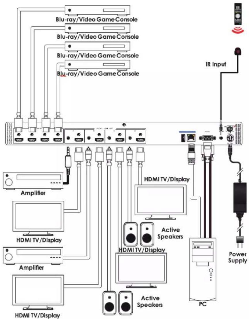
7. CONNECTION DIAGRAM
flowchart
graph TD
    A["Blu-ray/Video Game Console"] --> B["Amplifier"]
    C["Blu-ray/Video Game Console"] --> D["HDMI TV/Display"]
    E["Blu-ray/Video Game Console"] --> F["Amplifier"]
    G["Blu-ray/Video Game Console"] --> H["HDMI TV/Display"]
    I["IR Input"] --> J["Power Supply"]
    K["PC"] --> L["Active Speakers"]
    M["HDMI TV/Display"] --> N["Amplifier"]
    O["HDMI TV/Display"] --> P["Amplifier"]
    Q["Active Speakers"] --> R["HDMI TV/Display"]
    S["HDMI TV/Display"] --> T["Amplifier"]
    U["Active Speakers"] --> V["HDMI TV/Display"]
    W["Power Supply"] --> X["IR Input"]
8. SPECIFICATIONS
8.1 Technical Specifications
HDMI Bandwidth 18Gbps
Input Ports 4 x HDMI (Type-A)
Output Ports 4 x HDMI (Type-A)
4 x Analog Stereo (3.5mm)
Control Ports 1 x RS-232 (DE-9)
1 x Ethernet (RJ-45)
1 x IR Extender (3.5mm)
Service Port 1 x USB 2.0 (Type A)
IR Frequency 38kHz
Baud Rate 19200
Power Supply 24V/2.7A DC
(US/EU standards, CE/FCC/UL certified)
ESD Protection (HBM) 38kV (Air Discharge)
34kV (Contact Discharge)
Dimensions (W x H x D) 438mm x 49mm x 269mm [Case Only]
482mm x 49mm x 274mm [All Inclusive]
Weight 2.99kg
Chassis Material Metal (Steel)
Chassis Color Black
Operating Temperature 0^ - 40^/32^ - 104^
Storage Temperature -20^ - 60^/-4^ - 140^
Relative Humidity 20 - 90% RH (Non-condensing)
Power Consumption 34W
8.2 Video Specifications
| Supported Resolutions (Hz) | Input | Output |
| HDMI | HDMI | |
| 720 x 400p@70/85 | √ | √ |
| 640 x 480p@60/72/75/85 | √ | √ |
| 720 x 480i@60 | √ | √ |
| 720 x 480p@60 | √ | √ |
| 720 x 576i@50 | √ | √ |
| 720 x 576p@50 | √ | √ |
| 800 x 600p@56/60/72/75/85 | √ | √ |
| 848 x 480p@60 | √ | √ |
| 1024 x 768p@60/70/75/85 | √ | √ |
| 1152 x 864p@75 | √ | √ |
| 1280 x 720p@50/60 | √ | √ |
| 1280 x 768p@60/75/85 | √ | √ |
| 1280 x 800p@60/75/85 | √ | √ |
| 1280 x 960p@60/85 | √ | √ |
| 1280 x 1024p@60/75/85 | √ | √ |
| 1360 x 768p@60 | √ | √ |
| 1366 x 768p@60 | √ | √ |
| 1400 x 1050p@60 | √ | √ |
| 1440 x 900p@60/75 | √ | √ |
| 1600 x 900p@60RB | √ | √ |
| 1600 x 1200p@60 | √ | √ |
| 1680 x 1050p@60 | √ | √ |
| 1920 x 1080i@50/60 | √ | √ |
| 1920 x 1080p@24/25/30 | √ | √ |
| 1920 x 1080p@50/60 | √ | √ |
| 1920 x 1200p@60RB | √ | √ |
| 2560 x 1440p@60RB | √ | √ |
| 2560 x 1600p@60RB | √ | √ |
| 2048 x 1080p@24/25/30 | √ | √ |
| 2048 x 1080p@50/60 | √ | √ |
| 3840 x 2160p@24/25/30 | √ | √ |
| 3840 x 2160p@50/60 (4:2:0) | √ | √ |
| 3840 x 2160p@24, HDR10 | √ | √ |
| 3840 x 2160p@50/60 (4:2:0), HDR10 | √ | √ |
| 3840 x 2160p@50/60 | √ | √ |
| 4096 x 2160p@24/25/30 | √ | √ |
| 4096 x 2160p@50/60 (4:2:0) | √ | √ |
| 4096 x 2160p@24, HDR10 | √ | √ |
| 4096 x 2160p@50/60 (4:2:0), HDR10 | √ | √ |
| 4096 x 2160p@50/60 | √ | √ |
8.3 Audio Specifications
8.3.1 Digital Audio
| HDMI Input/Output | |
| LPCM | |
| Max Channels | Click Start, type “cmd” in the search field, and press Enter. |
| Sampling Rate (kHz) | Click Start > Run, type “cmd”, and press Enter. |
| Bitstream | |
| Supported Formats | Standard & High-Definition |
8.3.2 Analog Audio
| Analog Output | |
| Max Audio Level | 2Vrms |
| THD+N | <-60dB@0dBFS 1kHz (A-wt) |
| SNR | >70dB@0dBFS |
| Frequency Response | <33dB@20Hz~20kHz |
| Crosstalk | <-60dB@10kHz |
| Impedance | 470Ω |
| Type | Unbalanced |
8.4 Cable Specifications
| Cable Length | 1080p 4K30 4K60 | |||
| 8-bit 12-bit | (4:4:4)8-bit | (4:4:4)8-bit | ||
| High Speed HDMI Cable | ||||
| HDMI Input | 15m 10m | 5m 3m | ||
| HDMI Output | 15m 10m | 5m 3m | ||
Bandwidth Category Examples:
• 1080p (FHD Video)
- Up to 1080p@60Hz, 12-bit color
- Data rates lower than 5.3Gbps or below 225MHz TMDS clock
• 4K30 (UHD Video)
- 4K@24/25/30Hz & 4K@50/60Hz (4:2:0), 8-bit color
- Data rates higher than 5.3Gbps or above 225MHz TMDS clock but below 10.2Gbps
• 4K60 (UHD+ Video)
- 4K@50/60Hz (4:4:4, 8-bit)
- 4K@50/60Hz (4:2:0, 10-bit HDR)
- Data rates higher than 10.2Gbps
9. ACRONYMS
| ACRONYM COMPLETE TERM | |
| ASCII | American Standard Code for Information Interchange |
| Cat.5e | Enhanced Category 5 cable |
| Cat.6 | Category 6 cable |
| Cat.6A | Augmented Category 6 cable |
| Cat.7 | Category 7 cable |
| CEC | Consumer Electronics Control |
| CLI | Command-Line Interface |
| DAC | Digital-to-Analog Converter |
| dB | Decibel |
| DHCP | Dynamic Host Configuration Protocol |
| DVI | Digital Visual Interface |
| EDID | Extended Display Identification Data |
| Gbps | Gigabits per second |
| GUI | Graphical User Interface |
| HDCP | High-bandwidth Digital Content Protection |
| HDMI | High-Definition Multimedia Interface |
| HDR | High Dynamic Range |
| HDTV | High-Definition Television |
| IP | Internet Protocol |
| IR | Infrared |
| kHz | Kilohertz |
| LAN | Local Area Network |
| LCD | Liquid-Crystal Display |
| LED | Light-Emitting Diode |
| LPCM | Linear Pulse-Code Modulation |
| MHz | Megahertz |
| OSD | On-Screen Display |
| SNR | Signal-to-Noise Ratio |
| TCP | Transmission Control Protocol |
| THD+N | Total Harmonic Distortion plus Noise |
| TMDS | Transition-Minimized Differential Signaling |
| UHD | 4K Ultra-High-Definition (10.2Gbps max) |
| UHD+ | 4K Ultra-High-Definition (18Gbps max) |
| UHDTV | Ultra-High-Definition Television |
| USB | Universal Serial Bus |
| VGA | Video Graphics Array |
| WUXGA (RB) | Widescreen Ultra Extended Graphics Array(Reduced Blanking) |
| XGA | Extended Graphics Array |
| Ω | Ohm |
10. Customer Service
The return of a product to our Customer Service implies the full agreement of the terms and conditions hereinafter. There terms and conditions may be changed without prior notice.
1. Warranty
The limited warranty period of the product is fixed 3 (three) years.
Scope
These terms and conditions of Customer Service apply to the customer service provided for the products or any other items sold by authorized distributor only.
2. Warranty Exclusions:
Warranty expiration.
- Factory applied serial number has been altered or removed from the product. Damage, deterioration or malfunction caused by: Normal wear and tear.
- Use of supplies or parts not meeting our specifications.
- No certificate or invoice as the proof of warranty.
- The product model showed on the warranty card does not match with the model of the product for repairing or had been altered.
• Damage caused by force majeure.
• Servicing not authorized by distributor. - Any other causes which does not relate to a product defect. Shipping fees, installation or labor charges for installation or setup of the product.
3. Documentation:
Customer Service will accept defective product(s) in the scope of warranty coverage at the sole condition that the defeat has been clearly defined, and upon reception of the documents or copy of invoice, indicating the date of purchase, the type of product, the serial number, and the name of distributor.
Remarks: For further assistance or solutions, please contact your local distributor, or email directly to us at support@kanexpro.com
- SAFETY PRECAUTIONS
- TRADEMARK ACKNOWLEDGMENTS
- INTRODUCTION
- INTRODUCTION
- APPLICATIONS
- PACKAGE CONTENTS
- SYSTEM REQUIREMENTS
- FEATURES
- OPERATION CONTROLS AND FUNCTIONS
- Front Panel
- Rear Panel
- Remote Control
- IR Cable Pinout
- RS-232 Pinout and Defaults
- Front Panel LCD Menu
- WebGUI Control
- • Device Discovery
- - WebGUI Overview
- Switch Tab
- EDID Settings Tab
- Customer EDID Settings:
- System Settings Tab
- Telnet Control
- Serial and Telnet Commands
- OSDFCOLOR N1 N2←
- Available values for N2:
- OSDBGCOLOR N1 N2←
- OSDTS N1 N2←
- OSDINFO N1←
- CONNECTION DIAGRAM
- SPECIFICATIONS
- Technical Specifications
- Video Specifications
- Audio Specifications
- Digital Audio
- Analog Audio
- Cable Specifications
- Bandwidth Category Examples:
- • 1080p (FHD Video)
- • 4K30 (UHD Video)
- • 4K60 (UHD+ Video)
- ACRONYMS
- Customer Service
- Warranty
- Scope
- Warranty Exclusions:
- Documentation:
Brand : KanexPro
Model : HDMX44A-18G
Category : Router