Trans-AUTO - Generator Emko - Free user manual and instructions
Find the device manual for free Trans-AUTO Emko in PDF.

| Product Type | Generator |
| Brand | Emko |
| Model | Trans-AUTO |
| Power Output (Rated) | 3.5 kW |
| Peak Power | 4.0 kW |
| Fuel Type | Petrol (Gasoline) |
| Engine Type | 4-Stroke, Single Cylinder |
| Engine Displacement | 208 cc |
| Starting System | Recoil Start |
| Fuel Tank Capacity | 15 Liters |
| Run Time (50% Load) | 8 Hours |
| Output Voltage | 230 V AC |
| Output Frequency | 50 Hz |
| Socket Dimensions | 1x 16A, 2x 10A |
| Noise Level (@7m) | 72 dB(A) |
| Dimensions (L x W x H) | 600 x 450 x 450 mm |
| Net Weight | 42 kg |
| Wheel Kit | Included |
| Maintenance | Check oil every 20 hours; change oil every 100 hours |
| Safety Features | Overload protection, low oil shutdown |
Frequently Asked Questions - Trans-AUTO Emko
User questions about Trans-AUTO Emko
0 question about this device. Answer the ones you know or ask your own.
Ask a new question about this device
Download the instructions for your Generator in PDF format for free! Find your manual Trans-AUTO - Emko and take your electronic device back in hand. On this page are published all the documents necessary for the use of your device. Trans-AUTO by Emko.
USER MANUAL Trans-AUTO Emko
text_image
Trans AUTO EMKO ! LOG ▲ ✓ ▼ EKC PROG ON LOAD ← → G ENGINE RUNNING RESET AUTO TEST MAN I OCE EAC
TRANS-AUTO
AUTOMATIC START UNIT
FOR GAS/DIESEL/GASOLINE GENERATORS
WITH J1939 ECUs
User Manual
CONTENTS
1. Introduction Page 4
1.1 General Specifications.... Page 4
1.2 Warranty.... Page 4
1.3 Maintenance Page 4
1.4 Order Information...... Page 4
2.Installation.... Page 5
2.1 Unit Configuration Page 5
2.2 Panel Mounting.... Page 5
Figure 2.1 Front View...... Page 5
Figure 2.2 Panel Cut-Out.... Page 5
2.3 Electrical Connection.... Page 6
3. Definition Of Front Panel And Accessing To The Parameters...... Page 7
3.1 Front Panel Description.... Page 7
3.2 Accessing To The Operator Parameters...... Page 16
3.3 Accessing To The Technician Parameters...... Page 17
3.4 Changing And Saving Parameter Values Page 23
4.Parameters Page 24
4.1 Operator Parameters...... Page 24
4.1.1 Generator Page 24
4.2 Technician Parameters.... Page 25
4.2.1 System Page 25
4.2.2 Generator Page 30
4.2.3 Engine Page 33
4.2.4 Inputs Page 45
4.2.5 Outputs.... Page 61
4.2.6 Timers.... Page 70
4.2.7 Expansion Modules.... Page 71
4.2.8 User Adjustment.... Page 72
5.Specifications Page 76
6. Other Informations...... Page 77
Manufacturer's Name : EMKO ELEKTRONIK A.S.
Manufacturer's Address : Bursa Organize Sanayi Bölgesi ,
This declaration is issued under the sole responsibility of the manufacturer.
Product Name : Unit
Automatic Start
Type Number : TRANS-AUTO
Product Category : Electrical equipment for measurement, control and laboratory use
The product(s) that are stated above are fully in conformity with the essential requirements of Council Directives:
2014 / 35 / EU The Low Voltage Directive
2014 / 30 / EU The Electromagnetic Compatibility Directive
2011 / 65 / EU The Restriction of Hazardous Substances (RoHS 2) Directive
2015 / 863 / EU Amendment to Annex II of Directive 2011/65/EU
2017 / 2102 / EU Amendment to Annex II of Directive 2011/65/EU
This declaration is based on the full compliance of the products with the following European standards:
EN 61010-1:2010 Safety Requirements for Electrical Equipment for Measurement, Control and Laboratory Use
EN 61326-1:2013 Electrical Equipment for Measurement, Control and Laboratory Use - EMC Requirements
EN 60947-6-1:2005/A1:2014 Low - Voltage Switchgear and Controlgear - Part 6-1: Multiple Function Equipment - Transfer Switching Equipment
EN 50581:2012 Technical Documentation for The Assessment of Electrical and Electronic Products With Respect to The Restriction of Hazardous Substances
When and Where Issued Authorized Signature
22 ^No October 2021 Name : Arzu ATAN
BURSA-TÜRKİYE
Position
: Quality Manager
1. Introduction
1.1 General Specifications
The unit provides automatic start and stop the engine and protect the generator system. Both automatic and manual control is possible. A test mode is also available which allows the generator to be run for checking the generator system.
The unit has Dual Working feature. In the event of a remote start, group with high priority starts and takes the load. If both groups has no priority, the group with less working hour will start and take the load. To use Dual Working feature Dual Set expansion module must be used.
The unit calculates engine RPM from Magnetic Pickup sensor input (MPU) and/or generator voltage signal.
The unit monitors J1939 ECU messages and provides remote start/stop control via J1939 protocol (supported ECUs: Volvo EMS2, Volvo EDC4, Perkins, Scania S6, MAN MFR and standard messages).
The unit is extensively programmable through the front panel, with password protection on two levels. Operational parameters can also be monitored and controlled from a PC via a built-in USB communication port.
In the event that the engine fails to start on the first attempt, the attempt will be repeated a programmed number of times or until successful.
The unit monitors generator operation and gives warning of any faults that are detected. If a fault is detected, the unit shuts down the engine and shows the failure message on the LCD display and activates the internal sounder.
The unit has Remote Start input for remote control of the engine.
The configurable input-3 can be used as the water level sensing input.
The configurable input-7 can be used as the cabin temperature analog input.
1.2 Warranty
EMKO Elektronik warrants that the equipment delivered is free from defects in material and workmanship. This warranty is provided for a period of two years. The warranty period starts from the delivery date. This warranty is in force if duty and responsibilities which are determined in warranty document and instruction manual performs by the customer completely.
1.3 Maintenance
Repairs should only be performed by trained and specialized personnel. Cut power to the device before accessing internal parts.
Do not clean the case with hydrocarbon-based solvents (Petrol, Trichlorethylene etc.). Use of these solvents can reduce the mechanical reliability of the device. Use a cloth dampened in ethyl alcohol or water to clean the external plastic case.
1.4 Order Information
Trans-AUTO: Automatic start unit with USB communication
Trans-AUTO.RS485: Automatic start unit with USB and RS-485 communication
2. Installation

Before beginning installation of this product, please read the instruction manual and warnings below carefully.
A visual inspection of this product for possible damage occurred during shipment is recommended before installation. It is your responsibility to ensure that qualified mechanical and electrical technicians install this product.
If there is danger of serious accident resulting from a failure or defect in this unit, power off the system and separate the electrical connection of the device from the system.
Keep the power off until all of the wiring is completed so that electric shock and trouble with the unit can be prevented.
2.1 Unit Configuration
The unit can be programmed using the buttons and LCD display on the front panel or PC Software.
2.2 Panel Mounting
The unit is designed for panel mounting. Fixing is by two screw fixings.
1- Insert the unit in the panel cut-out from the front.
2- Insert the fixings in the slotted at the corners of the unit and tighten the fixing screws to secure the unit against the panel.

During the equipment is putted in hole on the metal panel while mechanical installation some metal burrs can cause injury on hands, you must be careful.
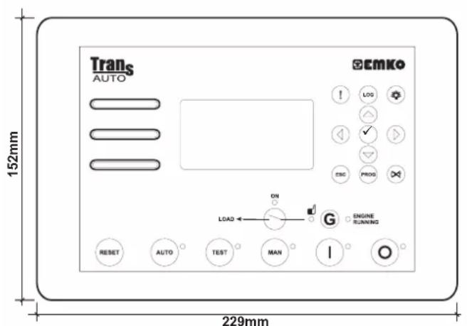
text_image
Trans AUTO 152mm 229mm ECMKO ! LOG ▲ ✓ ▽ ESC PROG ON LOAD ← → G ENGINE RUNNING RESET AUTO TEST MAN I O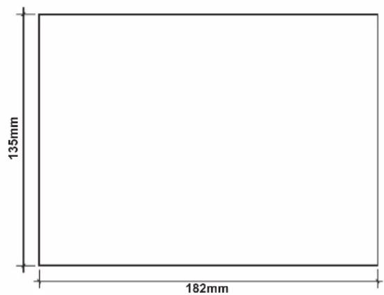
text_image
135mm 182mmFigure 2.1 Front View Figure 2.2 Panel Cut-Out
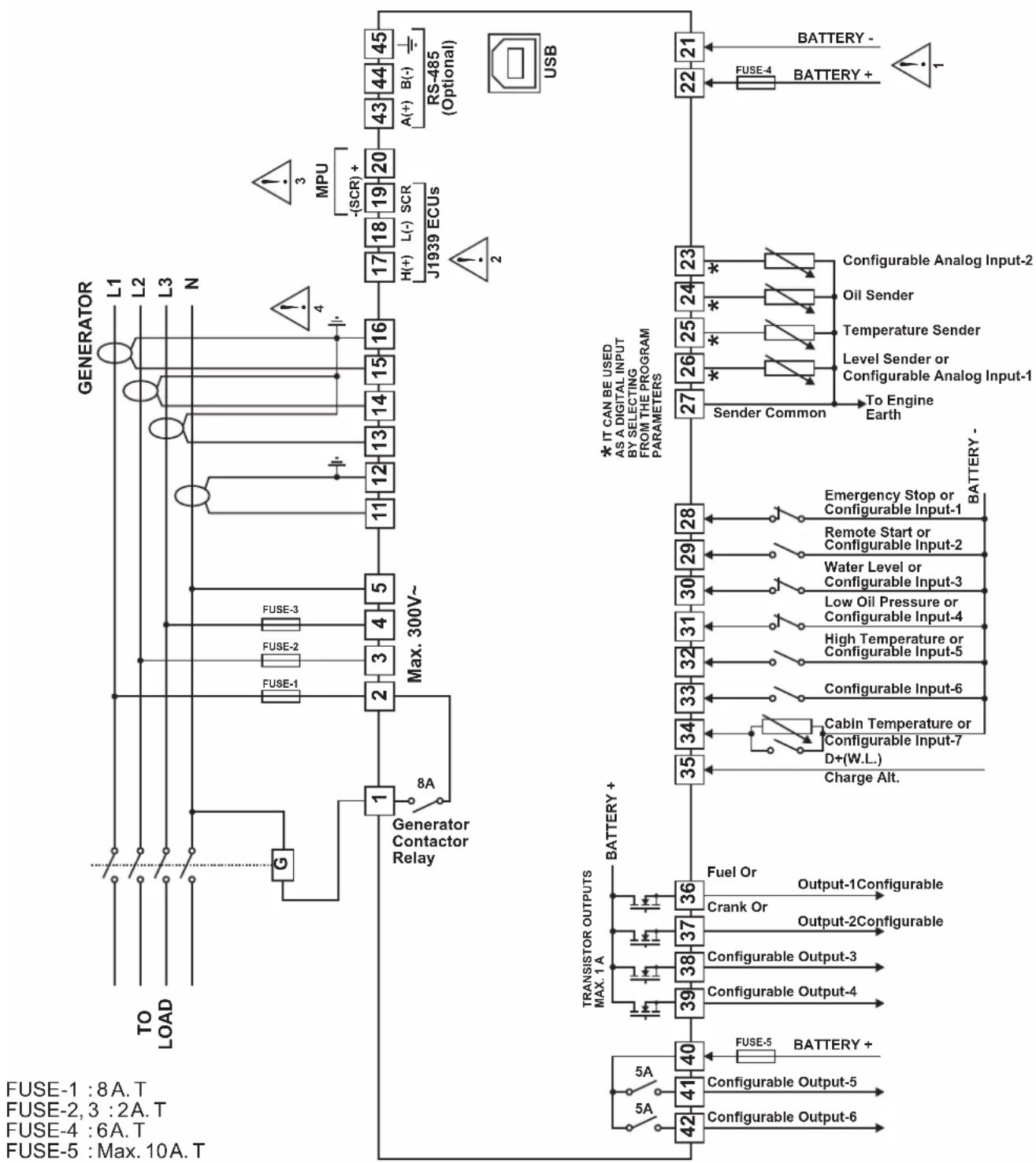
2.3 Electrical Connection
TRANS-AUTO three phase connections schematic
flowchart
graph TD
    A["GENERATOR"] -->|L1 L2 L3 N| B["Generator"]
    B --> C["Max. 300V~"]
    C --> D["Generator Contactor Relay"]
    D --> E["Transistor Outputs MAX. 1A"]
    E --> F["BATTERY +"]
    F --> G["FUSE-1:8A.T"]
    F --> H["FUSE-2:3:2A.T"]
    F --> I["FUSE-4:6A.T"]
    F --> J["FUSE-5:Max. 10A.T"]

    subgraph USB
        K["RS-485 (Optional)"]
        L["MPU -SCR"] --> M["17 H(+) L(-) SCR"]
        M --> N["J1939 ECUs"]
        O["22"] --> P["BATTERY -"]
        Q["21"] --> R["BATTERY +"]
    end

    subgraph MAX. 300V~
        S["1"] --> T["8A Generator Contactor Relay"]
        U["FUSE-3"] --> V["FUSE-2"]
        W["FUSE-1"] --> X["FUSE-1"]
        Y["3"] --> Z["4"]
        AA["5"] --> AB["3"]
        AC["1"] --> AD["2"]
    end

    subgraph BATTERY +
        AE["28"] --> AF["BATTERY -"]
        AG["29"] --> AH["BATTERY -"]
        AI["30"] --> AJ["BATTERY -"]
        AK["31"] --> AL["BATTERY -"]
        AM["32"] --> AN["BATTERY -"]
        AO["33"] --> AP["BATTERY -"]
        AQ["34"] --> AR["BATTERY -"]
        AS["35"] --> AT["BATTERY -"]
        AU["Fuel Or Output-1Configurable"] --> AV["Crank Or Output-2Configurable"]
        AW["36"] --> AX["37"] --> AY["38"] --> AZ["39"] --> BA["40"] --> BB["FUSE-5 BATTERY +"]
        BC["41"] --> BD["BATTERY +"]
        BE["42"] --> BF["BATTERY +"]

1- Connect the unit as shown in the appropriate diagram. Be sure to connect the battery supply the right way round. External fuse is recommended. Stranded cable cross section: 1,5mm^2 , Solid cable cross section: 2,5mm^2 , The stripping length is 7 to 9 mm. Supply cables must comply with the requirements of IEC 60277 or IEC 60245.
2- The CAN interface requires that a 120 Ohms terminator is fitted to each end of the communications link. This termination resistor is fitted internally into the unit. So it is not required externally. Screened cable must be used for connecting the CAN, ensuring that the screen is grounded at one end ONLY.
3- Screened cable must be used for connecting the Magnetic Pickup, ensuring that the screen is grounded at one end ONLY.
4- Current transformers secondary should be grounded. The CT of 5VA is recommended. The unit has a burden of 0.5VA on the CT.
3. Front Panel Description And Accessing To The Parameters
3.1 Front Panel Description
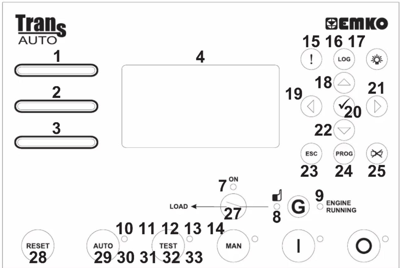
text_image
Trans AUTO 1 2 3 4 Emko 15 16 17 ! LOG 19 18 △ 21 ↓ ✓ 20 22 ESC PROG 23 24 25 7 ON LOAD ← 27 8 G 9 ENGINE RUNNING RESET 28 AUTO 29 30 31 32 33 MAN I O| Number | Comment |
| 1 | This LED indicates that a "Shutdown" alarm was detected. |
| 2 | This LED indicates that a "Warning" alarm was detected |
| 3 | This LED indicates that a "Maintenance" alarm was detected |
| 4 | This LCD display is used for displaying the electrical measurements during normal operation, and editing/inspecting programming parameters in program mode. |
| 7 | Th LED shows that the load is supplied from the generator.is |
| 8 | This LED indicates that Generator's stage and time required is ready to take over the load. |
| 9 | This LED indicates that the engine has started and is running. |
| 10 | This LED shows that the unit is in the AUTO mode. |
| 11 | This LED shows that the unit is in the TEST mode. |
| 12 | This LED shows that the unit is in the MANUAL mode. |
| 13 | In the MAN, AUTO and TEST modes, this LED indicates that the engine is starting up or is running. |
| 14 | This LED shows that the unit is in the STOP mode. |
| 15 | Warning and Alarm messages shortcut button. |
| 16 | Event Logs shortcut button. |
| 17 | The LAMPTEST button illuminates all LED indicators. |
| 18 | This button is used for showing previous parameters on the currently selected page in normal operation. In Programming mode, it operates as an Up button (changing cursor position) or Increment button (increase parameter value). |
| 19 | This button is used for showing previous page in normal operation. In Programming mode, it operates as an Left button (changing cursor position). |
| 20 | This button is used for entering parameter edit section and saving parameter value in programming mode. |
| 21 | This button is used for showing next page in normal operation. In Programming mode, it operates as an Right button (changing cursor position). |
| 22 | This button is used for showing next parameters on the currently selected page in normal operation. In Programming mode, it operates as an Down button (changing cursor position) or Decrement button (decrease parameter value). |
| 23 | The Escape button is used for exit previous section in programming mode. |
| 24 | When this button is pressed, the unit goes into its PROGRAMMING Mode. |
| 25 | This button will silence the alarm horn after a failure has been detected. |
| 27 | This button opens or closes the gen. contactor, only operative when manual mode is selected |
| 28 | This button will reset the controller after a failure has been detected. |
| 29 | TheAUTO button is used for changing operating mode of the unit to theAUTO Mode. |
| 30 | The TEST button is used for changing operating mode of the unit to the TEST Mode. |
| 31 | The MAN button is used for changing operating mode of the unit to the MANUALMode. |
| 32 | The STARTbutton is used for starting the engine when the unit is in the Manual Mode. |
| 33 | The STOPbutton is used for changing operating mode of the unit to the STOPMode. The generator is stopped. |
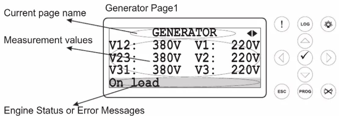
LCD display Description
text_image
Current page name Generator Page1 Measurement values GENERATOR V12: 380V V1: 220V V23: 380V V2: 220V V31: 380V V3: 220V On load Engine Status or Error Messages128x64 Dot-matrix LCD display.
Use the buttons to select which Data display page (screen) is to be displayed. Next and Previous When the Alarm (!) shortcut button is pressed, the Warning & Alarm display page is displayed. When the Event log (LOG) shortcut button is pressed, the Event Log display page is displayed.
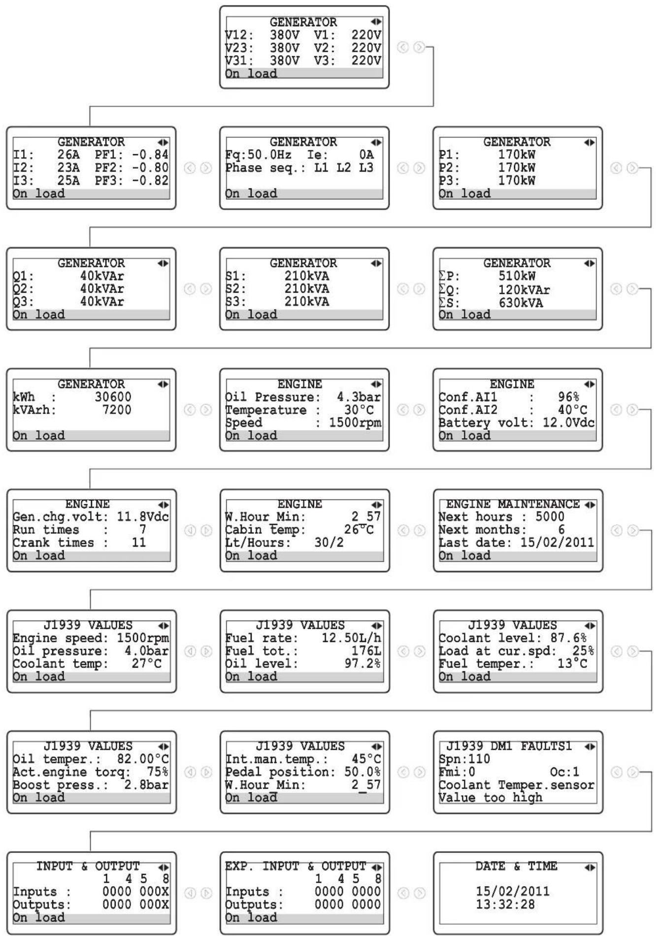
Data display pages on the LCD display;
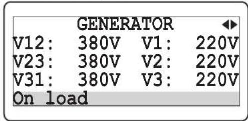
Generator Page1:
text_image
GENERATOR V12: 380V V1: 220V V23: 380V V2: 220V V31: 380V V3: 220V On loadV12: Generator voltage L1-L2
V23: Generator voltage L2-L3
V31: Generator voltage L3-L1
V1: Generator voltage L1-N
V2: Generator voltage L2-N
V3: Generator voltage L3-N
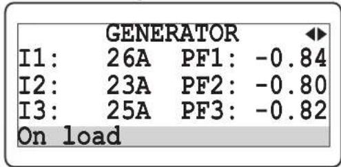
Generator Page2:
text_image
GENERATOR I1: 26A PF1: -0.84 I2: 23A PF2: -0.80 I3: 25A PF3: -0.82 On loadI1: Load Current L1
I2: Load Current L2
I3: Load Current L3
PF1: Generator power factor L1
PF2: Generator power factor L2
PF3: Generator power factor L3
Generator Page3:
text_image
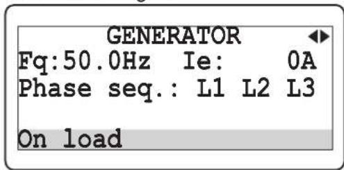
GENERATOR Fq:50.0Hz Ie: 0A Phase seq.: L1 L2 L3 On loadFq: Generator frequency
le: Earth Current
Phase Seq.: Generator phase sequence
Generator Page4:
text_image
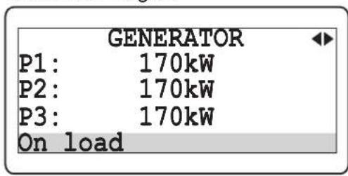
GENERATOR P1: 170kW P2: 170kW P3: 170kW On loadP1: Generator active power L1
P2: Generator active power L2
P3: Generator active power L3
Generator Page5:
text_image
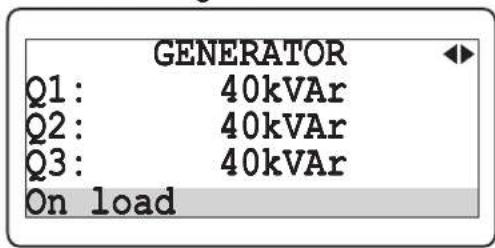
GENERATOR Q1: 40kVAr Q2: 40kVAr Q3: 40kVAr On loadQ1: Generator reactive power L1
Q2: Generator reactive power L2
Q3: Generator reactive power L3
Generator Page6:
text_image
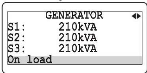
GENERATOR S1: 210kVA S2: 210kVA S3: 210kVA On loadS1: Generator apparent power L1
S2: Generator apparent power L2
S3: Generator apparent power L3
Generator Page7:
text_image
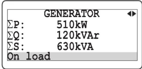
GENERATOR ΣP: 510kW ΣQ: 120kVAr ΣS: 630kVA On loadΣP: Generator total active power
ΣQ: Generator total reactive power
ΣS: Generator total apparent power
Generator Page8:
text_image
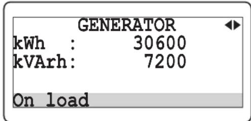
GENERATOR kWh : 30600 kVArh: 7200 On loadkWh: Generator active energy
KVArh: Generator reactive energy
Engine Page1:
text_image
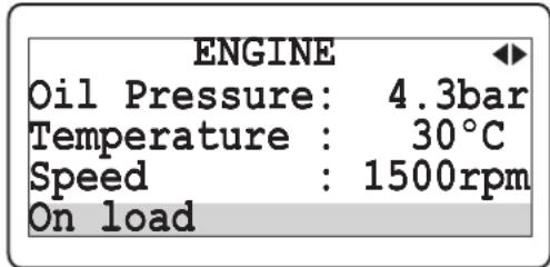
ENGINE Oil Pressure: 4.3bar Temperature : 30°C Speed : 1500rpm On loadOil pressure: Oil pressure sender input value
Temperature: Coolant temperature sender input value
Speed: Engine speed
Engine Page2:
text_image
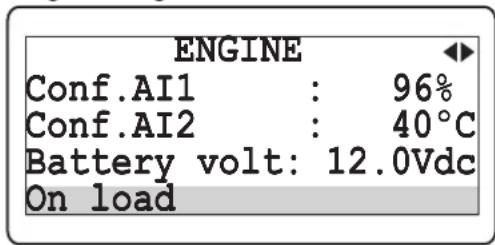
ENGINE Conf.AI1 : 96% Conf.AI2 : 40°C Battery volt: 12.0Vdc On loadConf. AI1: Configurable Analog Input-1 value
Conf. AI2: Configurable Analog Input-2 value
Battery volt: Battery supply voltage
Engine Page3:
text_image
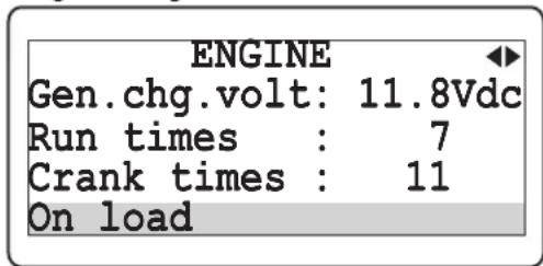
ENGINE Gen.chg.volt: 11.8Vdc Run times : 7 Crank times : 11 On loadGen.chg.volt: Charge generator voltage
Run times: Number of generator runs
Crank times: Number of generator starts
Engine Page4:
text_image
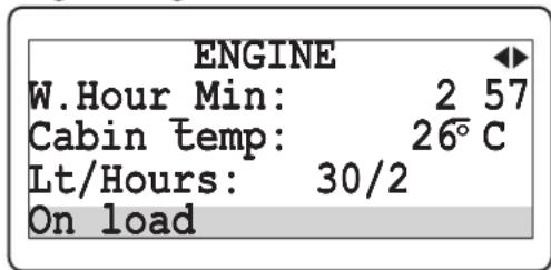
ENGINE W.Hour Min: 2 57 Cabin temp: 26°C Lt/Hours: 30/2 On loadW.Hour_Min: Engine running time (Hour and Minute)
Cabin temp: Cabin temperature
Lt/Hours: Fuel consumption
Engine Maintenance Page:
ENGINE MAINTENANCE ◀
Next hours : 5000
Next months: 6
Last date: 15/02/2011
On load
Next hours: The remaining hour for maintenance Next months: The remaining month for maintenance Last date: The last maintenance date
J1939 Values Page1:
J1939 VALUES
Engine speed: 1500rpm
Oil pressure: 4.0bar
Coolant temp: 27°C
On load
Engine speed: Engine speed via J1939 Oil pressure: Oil pressure via J1939 Coolant temp: Coolant temperature via J1939
J1939 Values Page2:
J1939 VALUES
Fuel rate: 12.50L/h
Fuel tot.: 176L
Oil level: 97.2%
On load
Fuel rate: Fuel rate via J1939 Fuel tot.: Fuel total used via J1939 Oil level: Oil level via J1939
J1939 Values Page3:
J1939 VALUES
Coolant level: 87.6%
Load at cur.spd: 25%
Fuel temper.: 13°C
On load
Coolant level: Coolant level via J1939 Load at cur.spd: Load at current speed via J1939 Fuel temper.: Fuel temperature via J1939
J1939 Values Page4:
J1939 VALUES
Oil temper.: 82.00°C
Act.engine torq: 75%
Boost press.: 2.8bar
On load
Oil temper.: Oil temperature via J1939 Act.engine torq: Actual engine torque via J1939 Boost press.: Boost pressure via J1939
J1939 Values Page5:
J1939 VALUES
Int.man.temp.: 45°C
Pedal position: 50.0%
W.hour Min: 2_57
On load
Int.man.temp.: Intake manifold temperature via J1939 Pedal position: Accelerator pedal position via J1939 W.hour_Min: Working hour and minute via J1939
J1939 DM1 (Active) Faults Page:
text_image
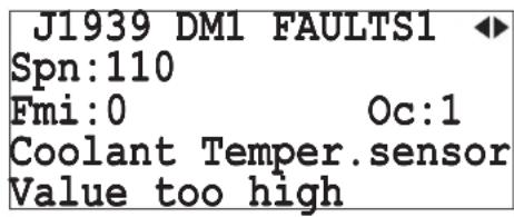
J1939 DM1 FAULTS1 ◀ Spn:110 Fmi:0 Oc:1 Coolant Temper.sensor Value too highSpn: Suspect parameter number (e.g. SPN = 110 corresponds to coolant temperature sensor) Fmi: Failure mode identifier (e.g. FMI = 0 means value too high) Oc: Occurrence count (if OC = 0, no alarm is present) The first 10 active alarm messages (Active Diagnostic Trouble Codes - DM1) with SPN, FMI, and OC are displayed). If more than one active fault condition is present, all of them is displayed sequentially by pressing Next and Previous buttons.
Input & Output Status Page:
text_image
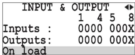
INPUT & OUTPUT ◀ 1 4 5 8 Inputs : 0000 000X Outputs: 0000 000X On loadInputs: Input status information. If an input is active, related digit is displayed as "1" else it is displayed as "0".
1: 203f.4n-1, Conf. in-2, Conf. in-3, Conf. in-4,
5: 607f.8n-5, Conf. in-6, Conf. in-7, Not available.
Outputs: Output status information. If an output is active, related digit is displayed as "1" else it is displayed as "0".
1: 2p8f.4ut-1, Conf. out-2, Conf. out-3, Conf. out-4,
5: 607f. out-5, Conf. out-6, Generator contactor,
8: Not available.
Exp. Input & Output Status Page:
text_image
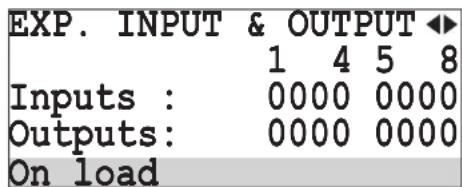
EXP. INPUT & OUTPUT ◀ 1 4 5 8 Inputs : 0000 0000 Outputs: 0000 0000 On loadInputs: Exp. input status information. If an input is active, related digit is displayed as "1" else it is displayed as "0".
1: Exp: conf. in-1, Exp. conf. in-2, Exp. conf. in-3,
4: 5x6: conf. in-4, Exp. conf. in-5, Exp. conf. in-6,
7: Exp. conf. in-7, Exp. conf. in-8.
Outputs: Exp. output status information. If an output is active, related digit is displayed as "1" else it is displayed as "0".
1: Exp: conf. out-1, Exp. conf. out-2, Exp. conf. out-3,
4: 5x6: conf. out-4, Exp. conf. out-5, Exp. conf. out-6,
7: Exp. conf. out-7, Exp. conf. out-8.
GPRS Page:
text_image
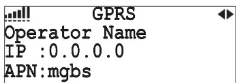
GPRS Operator Name IP :0.0.0.0 APN:mgbsSignal Quality: Signal Quality level indicator
Operator Name: Operator name
IP: Device IP value
APN: Access point name of the operator
GPS Page:
text_image
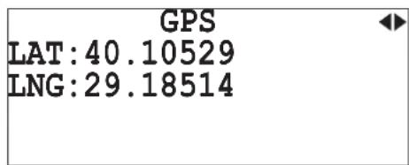
GPS LAT:40.10529 LNG:29.18514LAT: Latitude value of device's position
LNG: Longitude value of device's position
Date & Time Page:
text_image
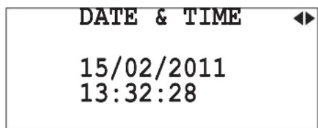
DATE & TIME 15/02/2011 13:32:28Date: Day, Month, Year.
Time: Hour, minute, second.
GenSet Page: (This page is only available at TRANS-AUTO.TR device)
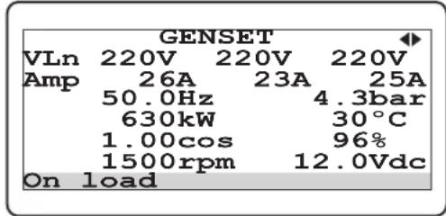
text_image
GENSET VLn 220V 220V 220V Amp 26A 23A 25A 50.0Hz 4.3bar 630kW 30°C 1.00cos 96% 1500rpm 12.0Vdc On loadVLn: Generator voltage L1-N, L2-N and L3-N
Amp: Generator current L1, L2 and L3
Hz: Generator frequency
bar: Oil pressure sender input value
kW: Generator total active power
°C: Coolant temperature sender input value
cos: Generator power factor average
%: Configurable Analog Input-1 value
rpm: Engine speed
Vdc: Battery supply voltage
Warning & Alarm display pages on the LCD display;
Warning & Alarm Page:
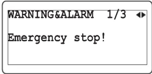
text_image
WARNING&ALARM 1/3 Emergency stop!1/3: The first message of current alarms.
Emergency stop!: This message indicates that an emergency stop alarm has occurred.
Event Log display pages on the LCD display;
Event Log Page1:
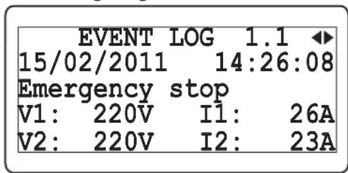
text_image
EVENT LOG 1.1 15/02/2011 14:26:08 Emergency stop V1: 220V I1: 26A V2: 220V I2: 23A1.1: The first page of related event log
Emergency stop: This message indicates that an emergency stop alarm has occurred. (Event history: 15/02/2011 date, 14:26:08 time).
V1: Generator voltage L1-N
I1: Load Current L1
V2: Generator voltage L2-N
I2: Load Current L2
Event Log Page2:
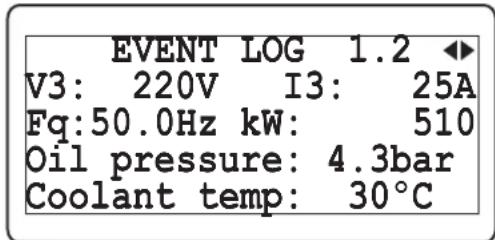
text_image
EVENT LOG 1.2 V3: 220V I3: 25A Fq:50.0Hz kW: 510 Oil pressure: 4.3bar Coolant temp: 30°C1.2: The second page of related event log
V3: Generator voltage L3-N
I3: Load Current L3
Fq: Generator frequency
kW: Generator total active power
Oil oressure: Oil pressure sender input value
Coolant temp: Coolant temperature sender input value
Event Log Page3:
text_image
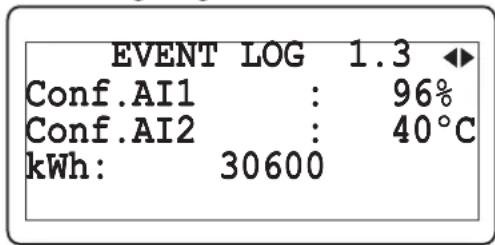
EVENT LOG 1.3 Conf.AI1 : 96% Conf.AI2 : 40°C kWh: 306001.3: The last page of related event log
Conf. AI1: Configurable Analog Input-1 value
Conf. AI2: Configurable Analog Input-2 value
kWh: Generator active energy
Events (from 1 to 50) can be displayed sequentially with the Next and Previous buttons.
Example-1: Displaying all pages.Data display
flowchart
graph TD
    A["GENERATOR"] --> B["I1: 26A PF1: -0.84\nI2: 23A PF2: -0.80\nI3: 25A PF3: -0.82\nOn load"]
    A --> C["Fq: 50.0Hz Ie: 0A\nPhase seq.: L1 L2 L3\nOn load"]
    A --> D["P1: 170kW\nP2: 170kW\nP3: 170kW\nOn load"]
    A --> E["GENERATOR"]
    E --> F["Q1: 40kVAr\nQ2: 40kVAr\nQ3: 40kVAr\nOn load"]
    A --> G["GENERATOR"]
    G --> H["kWh : 30600\nkVArh: 7200\nOn load"]
    A --> I["ENGINE"]
    I --> J["Gen.chg.volt: 11.8Vdc\nRun times : 7\nCrank times : 11\nOn load"]
    A --> K["ENGINE"]
    K --> L["W.Hour Min: 2.57\nCabin Temp: 26℃\nLt/Hours: 30/2\nOn load"]
    A --> M["ENGINE MAINTENANCE"]
    M --> N["Next hours : 5000\nNext months: 6\nLast date: 15/02/2011\nOn load"]
    A --> O["J1939 VALUES"]
    O --> P["Engine speed: 1500rpm\nOil pressure: 4.0bar\nCoolant temp: 27℃\nOn load"]
    A --> Q["J1939 VALUES"]
    Q --> R["Fuel rate: 12.50L/h\nFuel tot.: 176L\nOil level: 97.2%\nOn load"]
    A --> S["J1939 VALUES"]
    S --> T["Coolant level: 87.6%\nLoad at cur.spd: 25%\nFuel temper.: 13℃\nOn load"]
    A --> U["J1939 VALUES"]
    U --> V["Oil temper.: 82.00℃\nAct.engine torq: 75%\nBoost press.: 2.8bar\nOn load"]
    A --> W["J1939 VALUES"]
    W --> X["Int.man.temp.: 45℃\nPedal position: 50.0%\nW.Hour Min: 2.57\nOn load"]
    A --> Y["J1939 DM1 FAULTS1"]
    Y --> Z["Spn:110\nFmi:0 Oc:1\nCoolant Temper.sensor\Value too high"]
    A --> AA["INPUT & OUTPUT"]
    AA --> AB["Inputs : 0000 000X\nOutputs: 0000 000X\nOn load"]
    A --> AC["EXP. INPUT & OUTPUT"]
    AC --> AD["Inputs : 0000 0000\nOutputs: 0000 0000\nOn load"]
    A --> AE["DATE & TIME"]
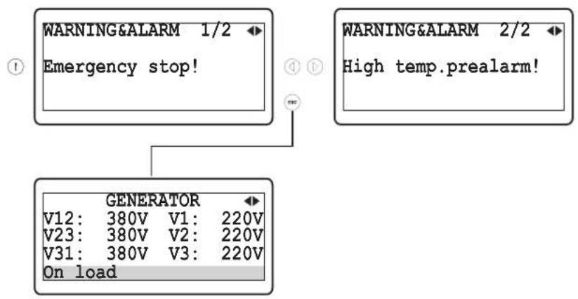
Example-2: Displaying all Warning&Alarm pagesdisplay
flowchart
graph TD
    A["WARNING&ALARM 1/2 Emergency stop!"] --> C["GENERATOR"]
    B["WARNING&ALARM 2/2 High temp.prealarm!"] --> C
    C --> D["V12: 380V V1: 220V"]
    C --> E["V23: 380V V2: 220V"]
    C --> F["V31: 380V V3: 220V"]
    C --> G["On load"]
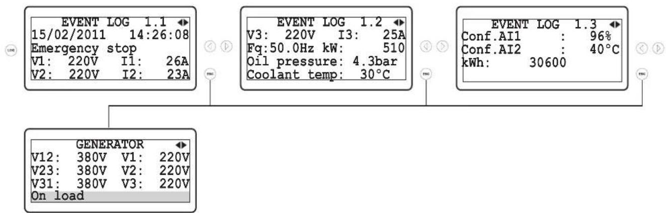
Example-3: Displaying all Event Log pagesdisplay
text_image
EVENT LOG 1.1 15/02/2011 14:26:08 Emergency stop V1: 220V I1: 26A V2: 220V I2: 23A EVENT LOG 1.2 V3: 220V I3: 25A Fq:50.0Hz kW: 510 Oil pressure: 4.3bar Coolant temp: 30°C EVENT LOG 1.3 Conf.AI1 : 96% Conf.AI2 : 40°C kWh: 30600 GENERATOR V12: 380V V1: 220V V23: 380V V2: 220V V31: 380V V3: 220V On loadLCD display language selection
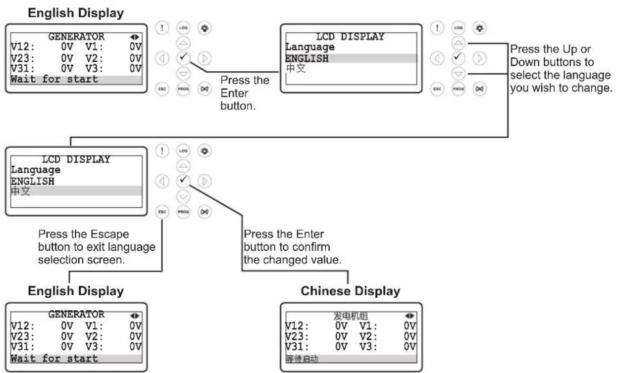
flowchart
graph TD
    A["English Display"] --> B["GENERATOR V12: 0V V1: 0V"]
    A --> C["V23: 0V V2: 0V"]
    A --> D["V31: 0V V3: 0V"]
    A --> E["Wait for start"]
    F["LCD DISPLAY Language ENGLISH 中文"] --> G["Press the Enter button."]
    H["LCD DISPLAY Language ENGLISH 中文"] --> I["Press the Enter button to confirm the changed value."]
    J["English Display"] --> K["GENERATOR V12: 0V V1: 0V"]
    J --> L["V23: 0V V2: 0V"]
    J --> M["V31: 0V V3: 0V"]
    J --> N["Wait for start"]
    O["Chinese Display"] --> P["发电机组 V12: 0V V1: 0V"]
    O --> Q["V23: 0V V2: 0V"]
    O --> R["V31: 0V V3: 0V"]
    O --> S["等待启动"]
    T["Press the Up or Down buttons to select the language you wish to change."] --> U["Press the Enter button to confirm the changed value."]
3.2 Accessing To The Operator Parameters
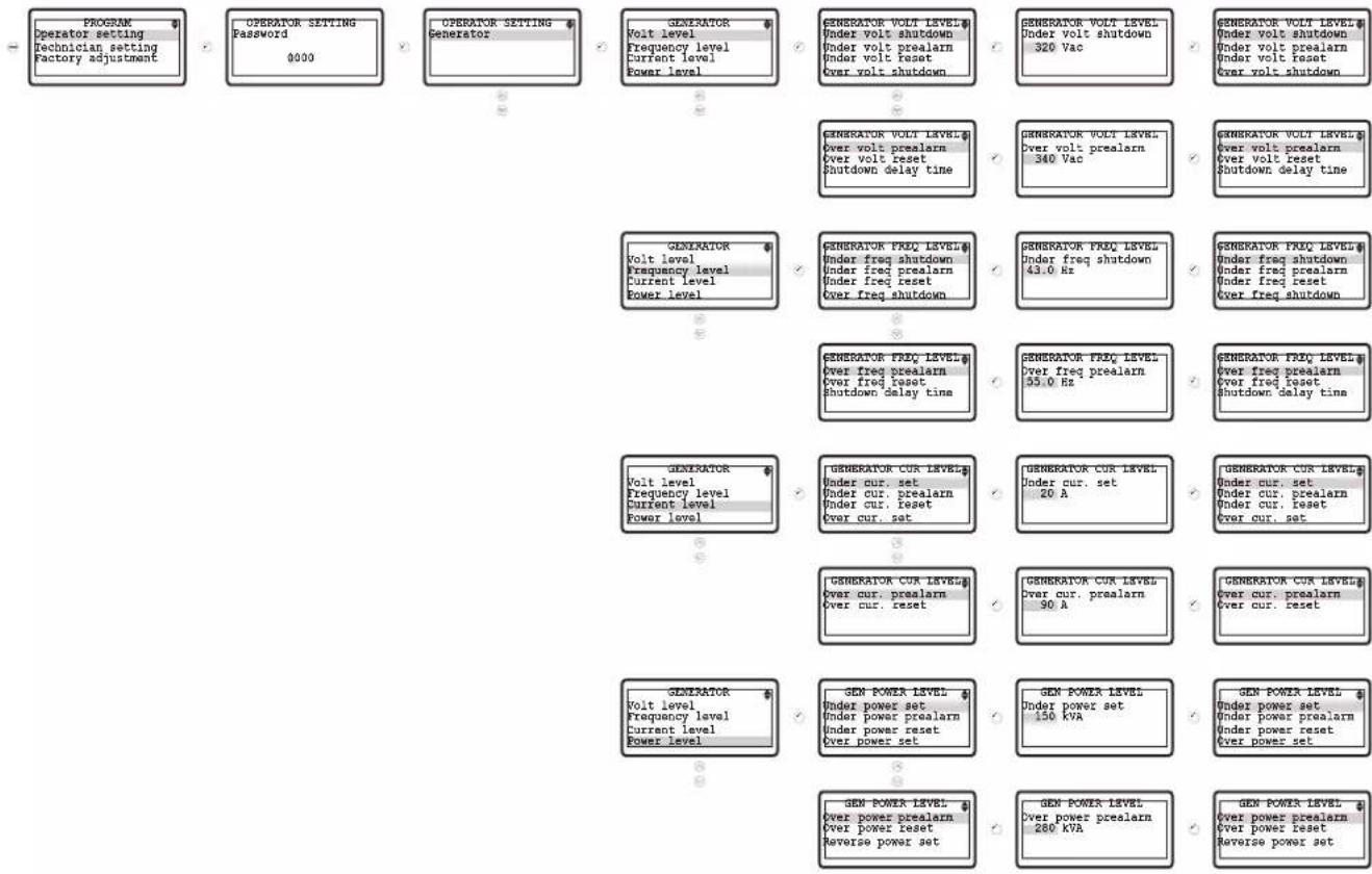
flowchart
graph TD
    A["PROGRAM Operator setting\nTechnician setting\nFactory adjustment"] --> B["OPERATOR SETTING Password 0000"]
    B --> C["OPERATOR SETTING Generator"]
    C --> D["GENERATOR Volt level\nFrequency level\nCurrent level\nPower level"]
    D --> E["GENERATOR VOLT LEVEL\nUnder volt shutdown\nUnder volt prealarm\nUnder volt reset\nOver volt shutdown"]
    E --> F["GENERATOR VOLT LEVEL\nUnder volt shutdown 320 Vac"]
    F --> G["GENERATOR VOLT LEVEL\nUnder volt shutdown\nUnder volt prealarm\nUnder volt reset\nOver volt shutdown"]
    G --> H["GENERATOR VOLT LEVEL\nOver volt prealarm\nOver volt reset\nShutdown delay time"]
    H --> I["GENERATOR VOLT LEVEL\nOver volt prealarm\n340 Vac"]
    I --> J["GENERATOR VOLT LEVEL\nOver volt prealarm\nOver volt reset\nShutdown delay time"]
    J --> K["GENERATOR VOLT LEVEL\nUnder freq shutdown\nUnder freq prealarm\nUnder freq reset\nOver freq shutdown"]
    K --> L["GENERATOR FREQ LEVEL\nUnder freq shutdown\nUnder freq prealarm\nUnder freq reset\nOver freq shutdown"]
    L --> M["GENERATOR FREQ LEVEL\nOver freq prealarm\nOver freq reset\nShutdown delay time"]
    M --> N["GENERATOR FREQ LEVEL\nOver freq prealarm\nOver freq reset\nShutdown delay time"]
    N --> O["GENERATOR FREQ LEVEL\nOver freq prealarm\nOver freq reset\nShutdown delay time"]
    O --> P["GENERATOR CUR LEVEL\nUnder cur. set\nUnder cur. prealarm\nUnder cur. reset\nOver cur. set"]
    P --> Q["GENERATOR CUR LEVEL\nUnder cur. set 20 A"]
    Q --> R["GENERATOR CUR LEVEL\nUnder cur. set\nUnder cur. prealarm\nUnder cur. reset\nOver cur. set"]
    R --> S["GENERATOR CUR LEVEL\nOver cur. prealarm\nOver cur. reset 90 A"]
    S --> T["GENERATOR CUR LEVEL\nOver cur. prealarm\nOver cur. reset"]
    T --> U["GENERATOR CUR LEVEL\nUnder cur. set\nUnder cur. prealarm\nUnder cur. reset\nOver cur. set"]
    U --> V["GENERATOR CUR LEVEL\nUnder cur. set\nUnder cur. prealarm\nUnder cur. reset\nOver cur. set"]
    V --> W["GENERATOR CUR LEVEL\nUnder cur. set\nUnder cur. prealarm\nUnder cur. reset\nOver cur. set"]
    W --> X["GENERATOR CUR LEVEL\nUnder cur. set\nUnder cur. prealarm\nUnder cur. reset\nOver cur. set"]
    X --> Y["GENERATOR CUR LEVEL\nUnder cur. set\nUnder cur. prealarm\nUnder cur. reset\nOver cur. set"]
    Y --> Z["GENERATOR CUR LEVEL\nUnder cur. set\nUnder cur. prealarm\nUnder cur. reset\nOver cur. set"]
    Z --> AA["GENERATOR CUR LEVEL\nUnder cur. set\nUnder cur. prealarm\nUnder cur. reset\nOver cur. set"]
    AA --> AB["GENERATOR CUR LEVEL\nUnder cur. set\nUnder cur. prealarm\nUnder cur. reset\nOver cur. set"]
    AB --> AC["GENERATOR CUR LEVEL\nUnder cur. set\nUnder cur. prealarm\nUnder cur. reset\nOver cur. set"]
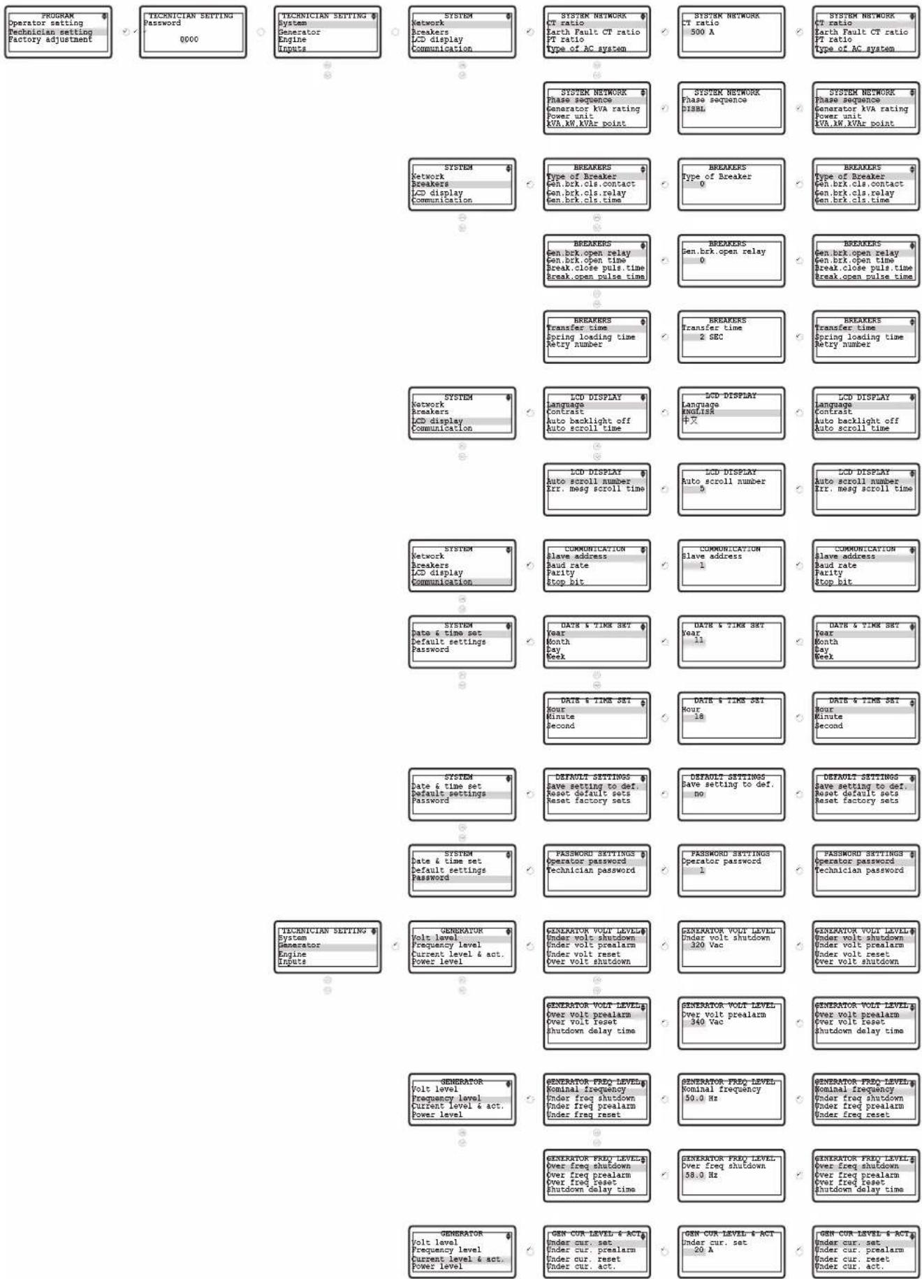
3.3 Accessing To The Technician Parameters