ES-9950 - Temperature regulator Emko - Free user manual and instructions
Find the device manual for free ES-9950 Emko in PDF.

User questions about ES-9950 Emko
0 question about this device. Answer the ones you know or ask your own.
Ask a new question about this device
Download the instructions for your Temperature regulator in PDF format for free! Find your manual ES-9950 - Emko and take your electronic device back in hand. On this page are published all the documents necessary for the use of your device. ES-9950 by Emko.
USER MANUAL ES-9950 Emko
text_image
PWR OUT 190 200 240 280 320 360 400 °C ES-9950ES-9950 96 x 96 1/4 DIN With Analogue Set Temperature Controller
- J type Thermocouple Input or,
K type Thermocouple Input or,
R type Thermocouple Input or,
S type Thermocouple Input or,
2 or 3-wire PT 100 Input (It must be determined in order) - ON/OFF operation
- Hysteresis value configurable with Jumper (It must be determined in order)
ABOUT INSTRUCTION MANUAL
Instruction manual of ES-9950 Analogue Temperature Controller consists of two main sections. Explanation of these sections are below. Also, there are other sections which include order information and technical specifications of the device. All titles and page numbers in instruction manual are in “CONTENTS” section. User can reach to any title with section number.
Installation:
In this section, physical dimensions of the device, panel mounting, electrical wiring, physical and electrical installation of the device to the system are explained.
Operation :
In this section, user interface of the device, definitions of operation form are explained.
Also in these sections, there are warnings to prevent serious injury while doing the physical and electrical mounting or using the device.
Explanation of the symbols which are used in these sections are given below.

This symbol is used for safety warnings. User must pay attention to these warnings.

This symbol is used to determine the dangerous situations as a result of an electric shock. User must pay attention to these warnings definitely.

This symbol is used to determine the important notes about functions and usage of the device.
CONTENTS
1.PREFACE......Page 5
1.1 GENERAL SPECIFICATIONS
1.2 ORDERING INFORMATION
1.3 WARRANTY
1.4 MAINTENANCE
2.INSTALLATION......Page 7
2.1 GENERAL DESCRIPTION
2.2 DIMENSIONS
2.3 PANEL CUT-OUT
2.4 ENVIRONMENTAL RATINGS
2.5 PANEL MOUNTING
2.6 INSTALLATION FIXING CLAMP
2.7 REMOVING FROM THE PANEL
3.ELECTRICAL WIRINGS......Page 12
3.1 TERMINAL LAYOUT AND CONNECTION INSTRUCTIONS
3.2 ELECTRICAL WIRING DIAGRAM
3.3 VIEW OF THE DEVICE LABEL
3.4 SUPPLY VOLTAGE INPUT CONNECTION OF THE DEVICE
3.5 TEMPERATURE SENSOR INPUT CONNECTION
3.5.1 TC (THERMOCOUPLE) CONNECTION
3.5.2 RTD CONNECTION
3.6 GALVANIC ISOLATION TEST VALUES OF ES-9950 ANALOGUE TEMPERATURE CONTROLLER
3.7 RELAY OUTPUT CONNECTION
4.FRONT PANEL DEFINITION AND OPERATION SETTINGS......Page 18
4.1 FRONT PANEL DEFINITION
4.2 OPERATION SETTINGS
4.2.1 SET VALUES
4.2.2 ADJUSTMENT OF HYSTERESIS VALUE
5.SPECIFICATIONS......Page 21
EU DECLARATION OF CONFORMITY
Manufacturer Company Name : Emko Elektronik A.S.
Manufacturer Company Address: DOSAB, Karanfil Sokak, No:6, 16369 Bursa, Turkiye
The manufacturer hereby declares that the product conforms to the following standards and conditions.
Product Name : Analogue Temperature Controller
Model Number : ES-9950
Type Number : ES-9950
Product Category : Electrical equipment for measurement, control and Laboratory use
Has been designed and manufactured to the following specifications :
EN 61000-6-4:2007 EMC Generic Emission Standard for the Industrial Environments
EN 61000-6-2:2005 EMC Generic Immunity Standard for the Industrial Environments
EN 61010-1:2001 Safety Requirements for electrical equipment for measurement, control And laboratory use
When and Where Issued Authorized Signature
16 ^th October 2009 Name : Serpil YAKIN
Bursa-TURKEY Position : Quality Manager
1.Preface
ES Series Analogue Temperature Controllers are designed for measuring and controlling temperature. They can be used in many applications with their simple and easy-use properties, On/Off control form.
Some application fields which they are used are below:
Application Fields
Glass
Plastic
Petro-Chemistry
Textile
Automotive
Machine production industries
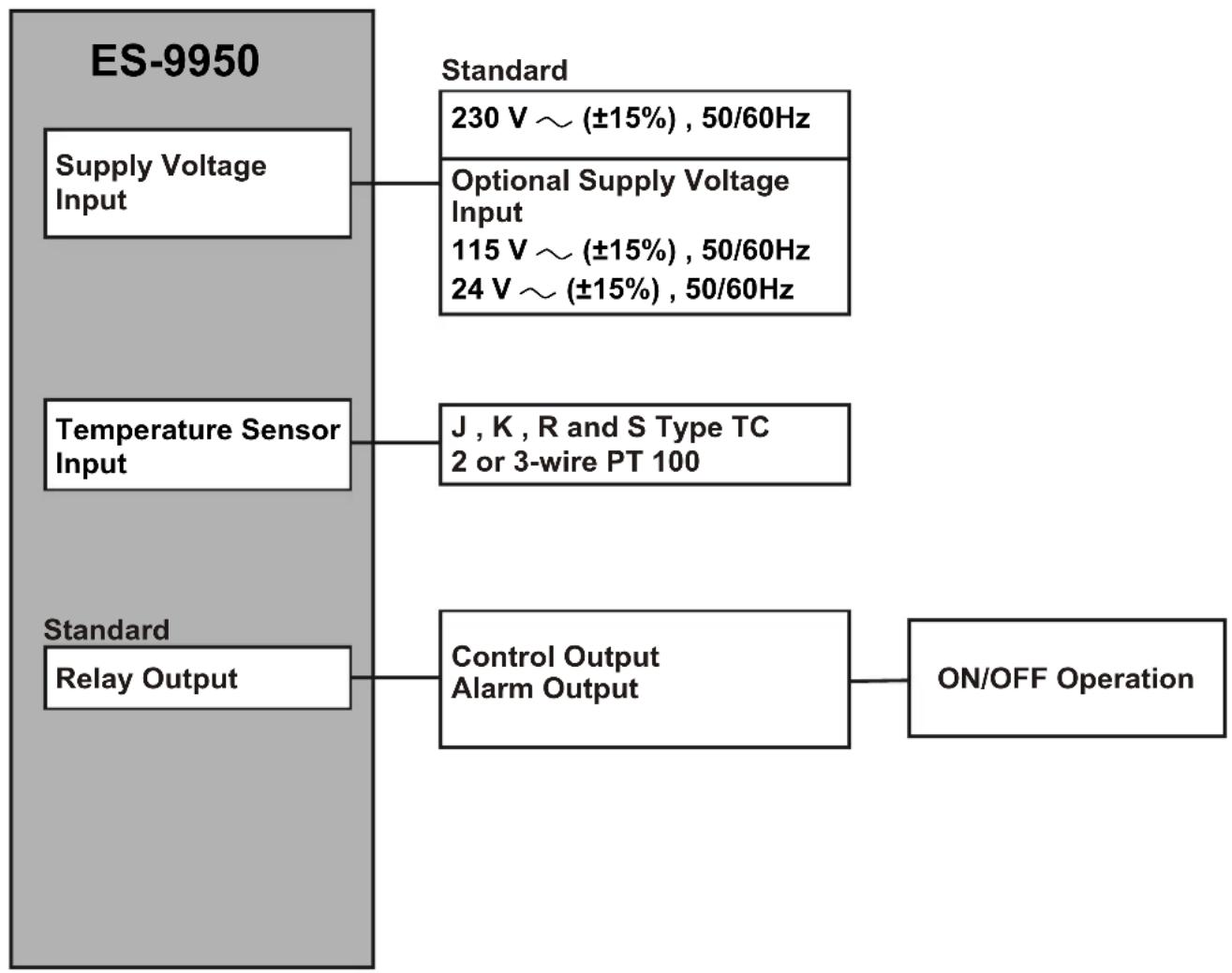
1.1 General Specifications
flowchart
graph TD
    A["ES-9950"] --> B["Supply Voltage Input"]
    A --> C["Temperature Sensor Input"]
    A --> D["Standard Relay Output"]
    B --> E["230 V ~ (±15%), 50/60Hz"]
    C --> F["J, K, R and S Type TC\n2 or 3-wire PT 100"]
    D --> G["Control Output\nAlarm Output"]
    G --> H["ON/OFF Operation"]
1.2 Ordering Information
| ES-9950 (96x96 1/4 DIN) | |||||||||||||||
| A | B | C | D | E | F | G | H | I | / | U | V | W | |||
| 0 | 0 | 10 | 0/ | 00 | / | 0 | |||||||||
| A | Supply Voltage |
| 3 | 24V ~ (±15%) 50/60Hz |
| 4 | 115V ~ (±15%) 50/60Hz |
| 5 | 230V ~ (±15%) 50/60Hz |
| 9 | Customer |
| Input TypeBC | Scale(°C) | ||
| 01 | PT 100, IEC751(ITS90) | -100.0°C | 100.0°C |
| 02 | PT 100, IEC751(ITS90) | 0.0°C | 200.0°C |
| 03 | PT 100, IEC751(ITS90) | 0°C | 400°C |
| 04 | J ,Fe CuNi IEC584.1(ITS90) | 0°C | 400°C |
| 05 | J ,Fe CuNi IEC584.1(ITS90) | 0°C | 800°C |
| 06 | K ,NiCr Ni IEC584.1(ITS90) | 0°C | 1200°C |
| 07 | S ,Pt10%Rh Pt IEC584.1(ITS90) | 0°C | 1600°C |
| 08 | R ,Pt13%Rh Pt IEC584.1(ITS90) | 0°C | 1600°C |
| E | Output-1 |
| 1 | Relay Output (5A@250V , 1 NO + 1 NC) |
| HysteresisU | |
| 2 | 1% of full scale |
| 3 | 2% of full scale |
All order information of ES-9950 Analogue Temperature Controller are given on the table at left. User may form appropriate device configuration from information and codes that at the table and convert it to the ordering codes.
Firstly, supply voltage then other specifications must be determined. Please fill the order code blanks according to your needs.
Please contact us, if your needs are out of the standards.

text_image
~ Symbol means Vac, --- Symbol means Vdc1.3 Warranty
EMKO Elektronik warrants that the equipment delivered is free from defects in material and workmanship. This warranty is provided for a period of two years. The warranty period starts from the delivery date. This warranty is in force if duty and responsibilities which are determined in warranty document and instruction manual performs by the customer completely.
1.4 Maintenance
Repairs should only be performed by trained and specialized personnel. Cut power to the device before accessing internal parts.
Do not clean the case with hydrocarbon-based solvents (Petrol, Trichlorethylene etc.). Use of these solvents can reduce the mechanical reliability of the device. Use a cloth dampened in ethyl alcohol or water to clean the external plastic case.
2. Installation

Before beginning installation of this product, please read the instruction manual and warnings below carefully.
In package,
- One piece unit
- Two pieces mounting clamps
- One piece instruction manual
A visual inspection of this product for possible damage occurred during shipment is recommended before installation. It is your responsibility to ensure that qualified mechanical and electrical technicians install this product.
If there is danger of serious accident resulting from a failure or defect in this unit, power off the system and separate the electrical connection of the device from the system.
The unit is normally supplied without a power switch or a fuse. Use power switch and fuse as required.
Be sure to use the rated power supply voltage to protect the unit against damage and to prevent failure.
Keep the power off until all of the wiring is completed so that electric shock and trouble with the unit can be prevented.
Never attempt to disassemble, modify or repair this unit. Tampering with the unit may results in malfunction, electric shock or fire.
Do not use the unit in combustible or explosive gaseous atmospheres.
During the equipment is putted in hole on the metal panel while mechanical installation some metal burrs can cause injury on hands, you must be careful.
Montage of the product on a system must be done with it's own fixing clamps. Do not do the montage of the device with inappropriate fixing clamps. Be sure that device will not fall while doing the montage.
It is your responsibility if this equipment is used in a manner not specified in this instruction manual.
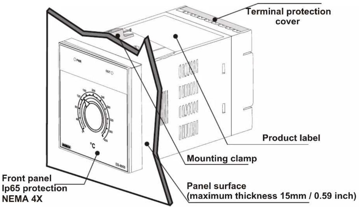
2.1 General Description
text_image
Terminal protection cover Product label Mounting clamp Front panel Ip65 protection NEMA 4X Panel surface (maximum thickness 15mm / 0.59 inch)2.2 Dimensions
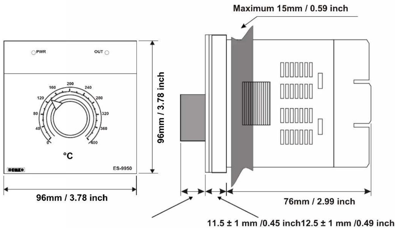
text_image
PWR OUT 160 200 240 120 280 80 320 40 360 0 400 °C 96mm / 3.78 inch ES-9950 Maximum 15mm / 0.59 inch 96mm / 3.78 inch 76mm / 2.99 inch 11.5 ± 1 mm /0.45 inch12.5 ± 1 mm /0.49 inch2.3 Panel Cut-Out
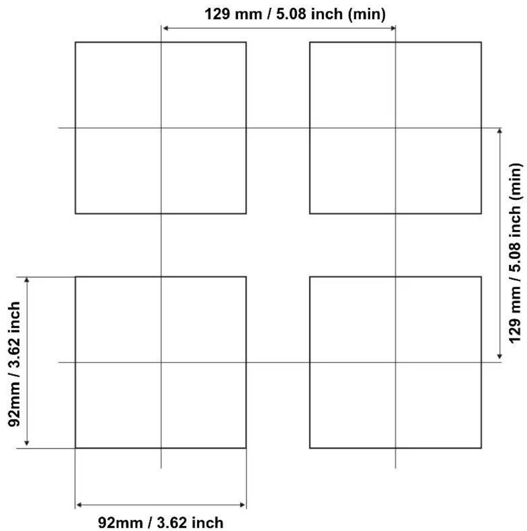
other
| Dimension | Value | | ----------------- | ------------ | | Width (mm) | 92mm / 3.62 inch | | Height (min) | 129 mm / 5.08 inch (min) | | Width (mm) | 92mm / 3.62 inch | | Height (min) | 129 mm / 5.08 inch (min) |2.4 Environmental Ratings
Operating Conditions

Operating Temperature : 0 to 50 °C

Max. Operating Humidity : 90% Rh (non-condensing)

Altitude : Up to 2000m.

Forbidden Conditions:
Corrosive atmosphere
Explosive atmosphere
Home applications (The unit is only for industrial applications)
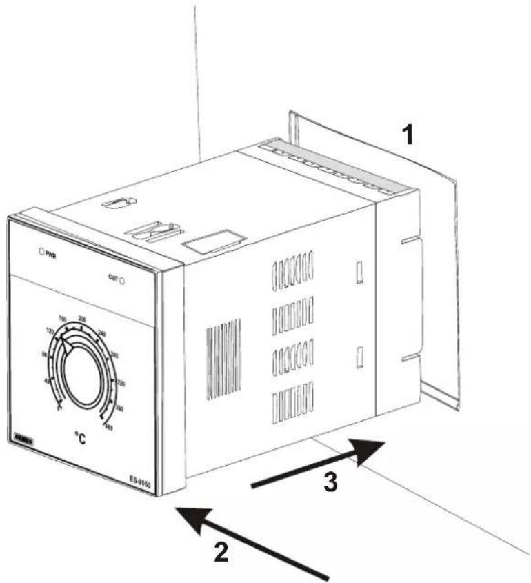
2.5 Panel Mounting
text_image
PHR OUT 1 100 200 240 120 300 360 40 480 560 °C ES-9150 3 21-Before mounting the device in your panel, make sure that the cut-out is of the right size.
2-Check front panel gasket position
3-Insert the device through the cut-out. If the mounting clamps are on the unit, put out them before inserting the unit to the panel.

During installation into a metal panel, care should be taken to avoid injury from metal burrs which might be present. The equipment can loosen from vibration and become dislodged if installation parts are not properly tightened. These precautions for the safety of the person who does the panel mounting.
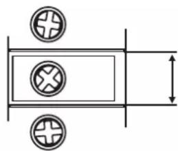
2.6 Installation Fixing Clamp

text_image
1 2 PWR OUT °C ES-0012The unit is designed for panel mounting.
1-Insert the unit in the panel cut-out from the front side.
2- Insert the mounting clamps to the holes that located top and bottom sides of device and screw up the fixing screws until the unit completely immobile within the panel

Montage of the unit to a system must be done with it's own fixing clamps. Do not do the montage of the device with inappropriate fixing clamps. Be sure that device will not fall while doing the montage.
2.7 Removing from the Panel

Before starting to remove the unit from panel, power off the unit and the related system.

text_image
2 1 PWR OUT °C ES-09550 31-Loosen the screws.
2-Pull mounting clamps from top and bottom fixing sockets.
3-Pull the unit through the front side of the panel
3.Electrical Wirings

You must ensure that the device is correctly configured for your application. Incorrect configuration could result in damage to the process being controlled, and/or personal injury. It is your responsibility, as the installer, to ensure that the configuration is correct.
Device parameters has factory default values. These parameters must be set according to the system's needs.

Only qualified personnel and technicians should work on this equipment. This equipment contains internal circuits with voltage dangerous to human life. There is severe danger for human life in the case of unauthorized intervention.

Be sure to use the rated power supply voltage to protect the unit against damage and to prevent failure.

Keep the power off until all of the wiring is completed so that electric shock and trouble with the unit can be prevented.
3.1 Terminal Layout and Connection Instructions

text_image
1 2 3 4 5 6 7 8 9 10 11 12 13 14 15 16 17 18 19 20 21 22 23 240.5Nm
natural_image
Pure electrical circuit lines without any symbols6 mm / 0.236 inch
Wire Size:
18 AWG / 1 mm²
Solid /Stranded

24 screws terminal
M3

Empty terminals

Torque 0.5 Nm

Screw driver 0.8x3mm
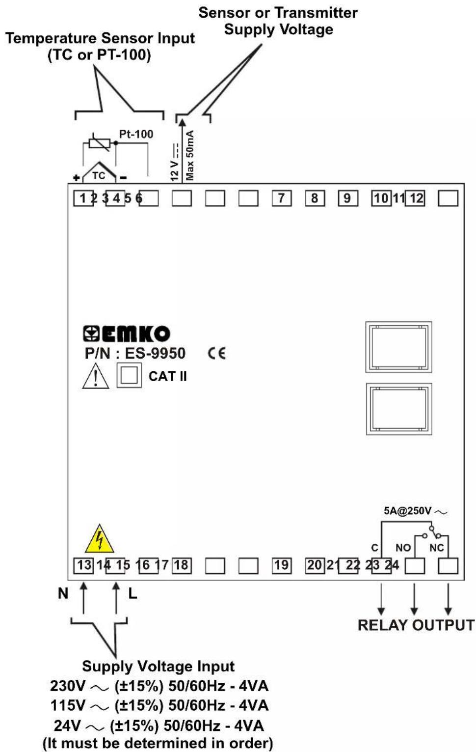
3.2 Electrical Wiring Diagram

Electrical wiring of the device must be the same as 'Electrical Wiring Diagram' below to prevent damage to the process being controlled and personnel injury.
text_image
Temperature Sensor Input (TC or PT-100) Sensor or Transmitter Supply Voltage Pt-100 Max 50mA 1 2 3 4 5 6 EMKO P/N : ES-9950 CE ! CAT II 13 14 15 16 17 18 N L Supply Voltage Input 230V ~ (±15%) 50/60Hz - 4VA 115V ~ (±15%) 50/60Hz - 4VA 24V ~ (±15%) 50/60Hz - 4VA (It must be determined in order)
Temperature Sensor Input is in CAT II class
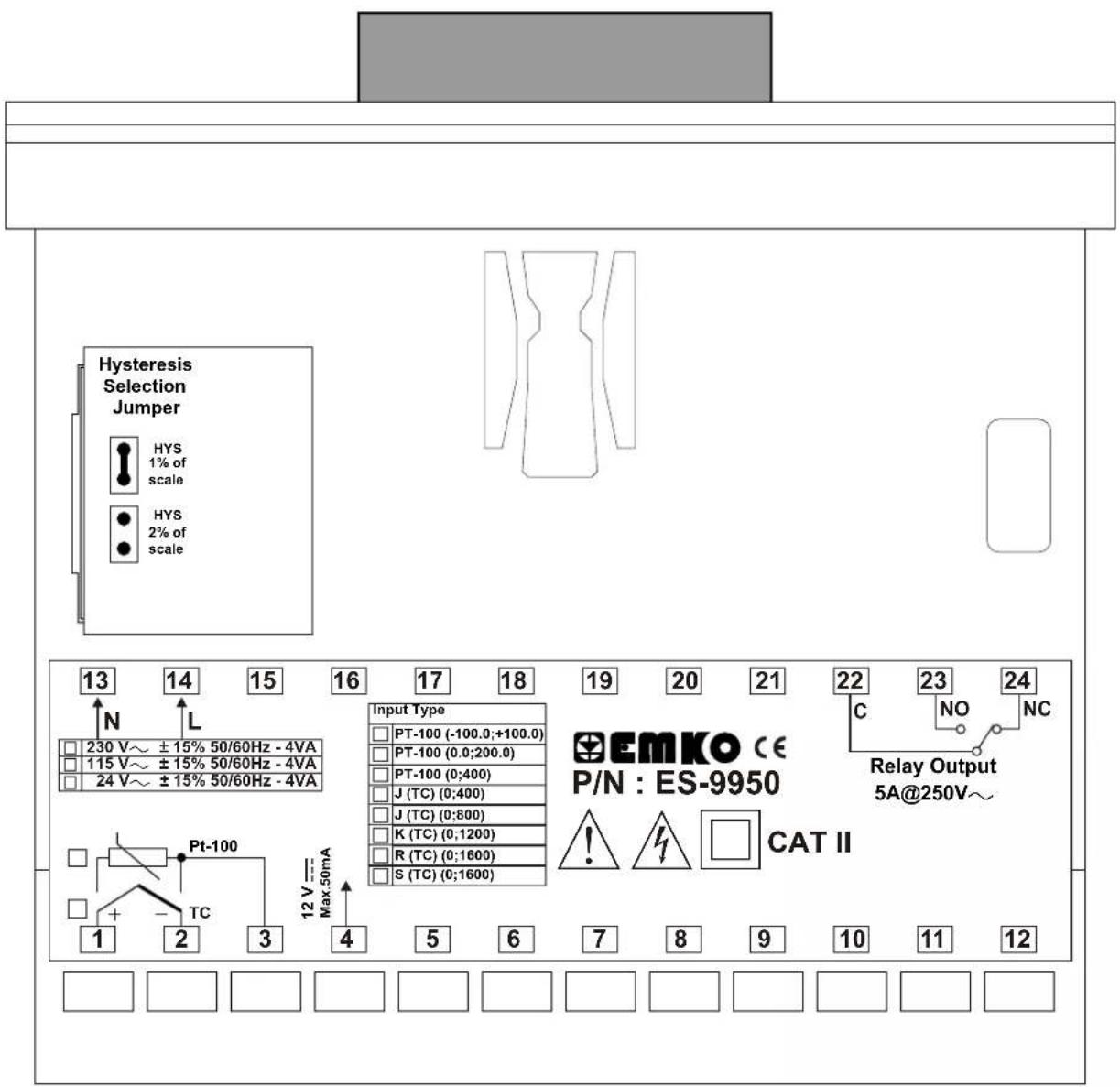
text_image
Hysteresis Selection Jumper HYS 1% of scale HYS 2% of scale 13 14 15 16 17 18 19 20 21 22 23 24 N L 230 V~ ±15% 50/60Hz - 4VA 115 V~ ±15% 50/60Hz - 4VA 24 V~ ±15% 50/60Hz - 4VA Input Type PT-100 (-100.0;+100.0) PT-100 (0.0;200.0) PT-100 (0;400) J (TC) (0;400) J (TC) (0;800) K (TC) (0;1200) R (TC) (0;1600) S (TC) (0;1600) EmKO CE P/N : ES-9950 C NO NC Relay Output 5A@250V~ Pt-100 1 2 3 4 5 6 7 8 9 10 11 12 12 V = Max.50mA3.4 Supply Voltage Input Connection of the Device
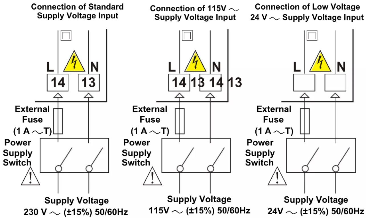

Supply voltage range must be determined in order. While installing the unit, supply voltage range must be controlled and appropriate supply voltage must be applied to the unit. Controlling prevents damages in unit and system and possible accidents as a result of incorrect supply voltage.

There is no power switch or fuse on the device. So a power switch and a fuse must be added to the supply voltage input. Power switch and fuse must be put to a place where user can reach easily.

Power switch must be two poled for separating phase and neutral. On/Off condition of power switch is very important in electrical connection. On/Off condition of power switch must be signed for preventing the wrong connection.

External fuse must be on phase connection in supply input.
3.5 Temperature Sensor Input Connection
3.5.1 TC (Thermocouple) Connection

flowchart
graph TD
    A["TC"] --> B["Box 1"]
    A --> C["Box 2"]
    A --> D["Box 3"]
    B --> E["+"]
    C --> F["-"]
    D --> G["+"]
    style A fill:#f9f,stroke:#333
    style B fill:#ccf,stroke:#333
    style C fill:#ccf,stroke:#333
    style D fill:#ccf,stroke:#333
Connect the wires with the polarity as shown in the figure left.

Always use compensation wire corresponding to the thermocouple used. If present, the shield must be connected to a proper ground.

Input resistance is greater than 10M Ω.
3.5.2 RTD Connection
flowchart
graph TD
    A["Pt-100"] --> B["1"]
    A --> C["2"]
    A --> D["3"]
    A --> E["Note 1"]
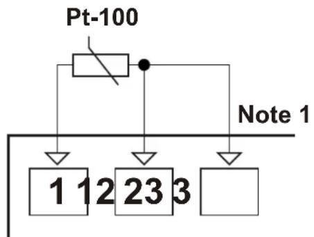
3-wire Pt-100 connection (with line compensation) (Max. Line impedance is 10 Ω)

flowchart
graph TD
    A["Pt-100"] --> B["Block 1"]
    A --> C["Block 2"]
    A --> D["Block 3"]
    style A fill:#f9f,stroke:#333
    style B fill:#ccf,stroke:#333
    style C fill:#ccf,stroke:#333
    style D fill:#ccf,stroke:#333
2-wire Pt-100 connection (without line compensation)
Note 1: In 3-wire system, use always cables of the same diameter (min 1mm^2 ) Always use wires of the same gauge and type whether a 2-wire or 3-wire system.
Note 2 : Install a jumper between terminals 2 and 3 when using a 2-wire RTD.
Note 3 : If the distance is longer than 10 meters, use 3-wire system

Input resistance is greater than 10M Ω.
3.6 Galvanic Isolation Test Values of ES-9950 Analogue Temperature Controller

flowchart
graph TD
    A["Supply Voltage Input"] --> B["Ground"]
    B --> C["Relay Output"]
    C --> D["Analogue Inputs"]
    D --> E["12V --- Sensor Supply Voltage"]
    E --> F["Ground"]
    style A fill:#f9f,stroke:#333
    style B fill:#ccf,stroke:#333
    style C fill:#cfc,stroke:#333
    style D fill:#fcc,stroke:#333
    style E fill:#cff,stroke:#333
    note1["2000V ~ ( For ES-9950.5....)"]
    note2["2000V ~ ( For ES-9950.4....)"]
    note3["500V ~ ( For ES-9950.3....)"]
    note1 -->|←→| B
    note2 -->|←→| B
    note3 -->|←→| B
    note1 -->|2000V ~| C
    note2 -->|2000V ~| C
    note3 -->|2000V ~| C
3.7 Relay Output Connection

text_image
Device C 22 NC 24 NO 23 5A ~ T Fuse Last Control Element (Contactor) Fuse Load L N
Fuses must be selected according to the applications
4. Front Panel Definition and Operation Settings
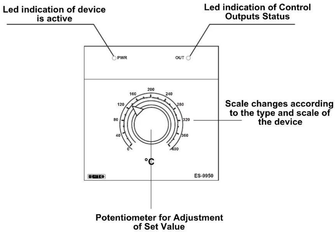
4.1 Front Panel Definition
text_image
Led indication of device is active Led indication of Control Outputs Status PWR OUT 160 200 240 120 280 80 320 40 360 0 400 °C ES-9950 Scale changes according to the type and scale of the device Potentiometer for Adjustment of Set Value4.2 Operation Settings
4.2.1 Set Values
Set value can be adjusted with Set Value Adjustment Potentiometer that is on the front panel. Set value range changes according to the type and scale of the device. Minimum and maximum values of Set value according to the device type are given below:
Set Values according to the Type and Scale of the Device
| For PT-100 (-100.0 to 100.0)°C |
| For PT-100 (0.0 to 200.0)°C |
| For PT-100 (0 to 400)°C |
| For J Type TC (0 to 400)°C |
| For J Type TC (0 to 800)°C |
| For K Type TC (0 to 1200)°C |
| For R Type TC (0 to 1600)°C |
| For S Type TC (0 to 1600)°C |
4.2.2 Adjustment of Hysteresis Value
In ON/OFF control algorithm, temperature value is tried to keep equal to set value by opening or closing completely last control element. ON/OFF controlled system, temperature value oscillates continuously. Temperature value's oscillation period or amplitude around set value changes according to controlled system. For reducing oscillation period of temperature value, a threshold zone is formed below or around set value and this zone is named hysteresis. Action of control output is described with figures below.

line
| Time | Temperature Set Value | |------|------------------------| | 0 | ON | | 1 | OFF | | 2 | ON | | 3 | OFF | | 4 | ON | | 5 | OFF | | 6 | ON | | 7 | OFF | | 8 | ON | | 9 | OFF | | 10 | ON | | 11 | OFF | | 12 | ON | | 13 | OFF | | 14 | ON | | 15 | OFF | | 16 | ON | | 17 | OFF | | 18 | ON | | 19 | OFF | | 20 | ON | | 21 | OFF | | 22 | ON | | 23 | OFF | | 24 | ON | | 25 | OFF | | 26 | ON | | 27 | OFF | | 28 | ON | | 29 | OFF | | 30 | ON | | 31 | OFF | | 32 | ON | | 33 | OFF | | 34 | ON | | 35 | OFF | | 36 | ON | | 37 | OFF | | 38 | ON | | 39 | OFF | | 40 | ON | | 41 | OFF | | 42 | ON | | 43 | OFF | | 44 | ON | | 45 | OFF | | 46 | ON | | 47 | OFF | | 48 | ON | | 49 | OFF | | 50 | ON | | 51 | OFF | | 52 | ON | | 53 | OFF | | 54 | ON | | 55 | OFF | | 56 | ON | | 57 | OFF | | 58 | ON | | 59 | OFF | | 60 | ON | | 61 | OFF | | 62 | ON | | 63 | OFF | | 64 | ON | | 65 | OFF | | 66 | ON | | 67 | OFF | | 68 | ON | | 69 | OFF | | 70 | ON | | 71 | OFF | | 72 | ON | | 73 | OFF | | 74 | ON | | 75 | OFF | | 76 | ON | | 77 | OFF | | 78 | ON | | 79 | OFF | | 80 | ON | | 81 | OFF | | 82 | ON | | 83 | OFF | | 84 | ON | | 85 | OFF | | 86 | ON | | 87 | OFF | | 88 | ON | | 89 | OFF | | 90 | ON | | 91 | OFF | | 92 | ON | | 93 | OFF | | 94 | ON | | 95 | OFF | | 96 | ON | | 97 | OFF | | 98 | ON | | 99 | OFF | | 100 | ON | | 101 | Off | | 102 | ON | | 103 | Off | | 104 | ON | | 105 | Off | | 106 | ON | | 107 | Off | | 108 | ON | | 109 | Off | | 110 | ON | | 111 | Off | | 112 | ON | | 113 | Off | | 114 | ON | | 115 | Off | | 116 | ON | | 117 | Off | | 118 | ON | | 119 | Off | | 120 | ON | | 121 | Off | | 122 | ON | | 123 | Off | | 124 | ON | | 125 | Off | | 126 | ON | | 127 | Off | | 128 | ON | | 129 | Off | | 130 | ON | | 131 | Off | | 132 | ON | | 133 | Off | | 134 | ON | | 135 | Off | | 136 | ON | | 137 | Off | | 138 | ON | | 139 | Off | | 140 | ON | | 141 | Off | | 142 | ON | | 143 | Off | | 144 | ON | | 145 | Off | | 146 | ON | | 147 | Off | | 148 | ON | | 149 | Off | | 150 | ON | | | |
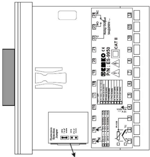
In operation with ON/OFF Control form; hysteresis value can be adjusted with Jumper on the device (It must be determined in order)
text_image
Hysteresis Selection Jumper 175 V 24 V 30 V Zn. r CCB 13 14 15 16 17 18 19 20 21 22 23 NC P/N: ES-9950 CAT II K1/10V 13V 13V 13V P1/10V 13V 13V 13V P1/10V 13V 13V 13V P1/10V 13V 13V 13V P1/10V 13V 13V 13V P1/10V 13V 13V 13V P1/10W 13V 13V 13V P1/10W 13V 13V 13V P1/10W 13V 13V 13V P1/10W 13V 13V 13V P1/10W 13V 13V 13V P1/10W 13V P1/10W 13V P1/10W 13V P1/10W 13V P1/10W 13V P1/10W 13V P1/10W 13V P1/10W 13V P1/10W 13V P1/10W P1/10W P1/10W P1/10W P1/10W P1/10W P1/10W P1/10W P1/10W P1/10W P1/10W P1/10W P1/10W P1/10W P1/10W A25 TO 2 2 4 5 6 7 8 9 10 11 12Jumper is under cover and cover is on top side of the device
Hysteresis Value Selection(It must be determined in order)
| [AOYZ] | 1% of full scale is selected |
 | 2% of full scale is selected |
Minimum and maximum value of hysteresis according to the type and scale of the device are given below:
If 1% of full scale is selected with Jumper, then hysteresis;
| For PT-100 (-100.0 to 100.0)°C : (0.0 to 2.0)°C |
| For PT-100 (0.0 to 200.0)°C : (0.0 to 2.0)°C |
| For PT-100 (0 to 400)°C : (0 to 4)°C |
| For J Type TC (0 to 400)°C : (0 to 4)°C |
| For J Type TC (0 to 800)°C : (0 to 8)°C |
| For K Type TC (0 to 1200)°C : (0 to 12)°C |
| For R Type TC (0 to 1600)°C : (0 to 16)°C |
| For S Type TC (0 to 1600)°C : (0 to 16)°C |
If 2% of full scale is selected with Jumper, then hysteresis;
| For PT-100 (-100.0 to 100.0)°C (0.0 to 4.0)°C |
| For PT-100 (0.0 to 200.0)°C : (0.0 to 4.0)°C |
| For PT-100 (0 to 400)°C : (0 to 8)°C |
| For J Type TC (0 to 400)°C : (0 to 8)°C |
| For J Type TC (0 to 800)°C : (0 to 16)°C |
| For K Type TC (0 to 1200)°C : (0 to 24)°C |
| For R Type TC (0 to 1600)°C : (0 to 32)°C |
| For S Type TC (0 to 1600)°C : (0 to 32)°C |
6. Specifications
| Device Type | : Analogue Temperature Controller |
| Housing&Mounting | : 96mm x 96mm x 100mmmm 1/4 DIN 43700 plasticHousing for panel mounting. Panel cut-out is 92x92mm. |
| Protection Class | : NEMA 4X (Ip65 at front, IP20 at rear). |
| Weight : Approximately 0.40 Kg. | |
| Environmental Ratings : Standard, indoor at an altitude of less than 2000 meterswith none condensing humidity. | |
| Storage/Operating Temperature | :-40 °C to +85 °C / 0 °C to +50 °C |
| Storage/Operating Humidity : 90 % max. (None condensing) | |
| Installation : Fixed installation | |
| Overvoltage Category : II | |
| Pollution Degree : II, office or workplace, none conductive pollution | |
| Operating Conditions : Continuous | |
| Supply Voltage and Power | : 230V ~ (±15%) 50/60 Hz. 4VA115V ~ (±15%) 50/60 Hz. 4VA24V ~ (±15%) 50/60 Hz. 4VA |
| Temperature Sensor Inputs : TC, RTD | |
| Thermocouple Input Types : J, K , R , S (IEC584.1)(ITS90) | |
| Thermoresistance Input Type | : PT-100. (IEC751)(ITS90) |
| Accuracy | : 1% of full scale for Thermocouple and Thermoresistance |
| Cold Junction Compensation | : Automatically ± 0.1°C/1°C. |
| Line Compensation | : Maximum 10 Ω . |
| Sensor Break Protection | : Upscale |
| Sampling Cycle | : 3 samples per second |
| Resolution of Set Point | : ± 0.2% of full scale |
| Accuracy of Set Point | : ±1% of full scale |
| Control Forms | : ON / OFF |
| Relay Output | : 5A@250V ~ (Electrical Life : 100.000 Operation (Full Load)) |
| Led Indicators | : PWR (Green) , OUT (Red) |
7. Other Informations
Manufacturer Information:
Emko Elektronik Sanayi ve Ticaret A.Ş.
Repair and Maintenance Service Information:
Emko Elektronik Sanayi ve Ticaret A.Ş.
Your Technology Partner

Thank you very much for your preference to use Emko Elektronik
Products.
www.emkoelektronik.com.tr