
DS-K1T680DFW - Access Control Hikvision - Free user manual and instructions
Find the device manual for free DS-K1T680DFW Hikvision in PDF.


| Product Type | Face Recognition Access Control Terminal |
| Brand | Hikvision |
| Model | DS-K1T680DFW |
| Display | 8-inch touch screen with bezel-less design |
| Camera | 2 MP wide-angle dual-lens |
| Face Recognition Distance | 0.3 m to 3 m |
| Face Recognition Speed | < 0.2 seconds per user |
| Face Recognition Accuracy | ≥ 99% |
| Face Capacity | Up to 100,000 |
| Card Capacity | Up to 100,000 |
| Event Capacity | Up to 150,000 |
| Authentication Methods | Face, fingerprint, card, password, QR code, or combination |
| Connectivity | Wi-Fi, 3G/4G (optional), RS-485, Wiegand, TCP/IP |
| Audio | Two-way audio with indoor station and main station |
| Power Supply | 12 VDC (use provided adapter; PoE not supported) |
| Power Consumption | < 24 W |
| Dimensions (Device) | Approx. 290 mm × 125 mm × 55 mm |
| Weight | Approx. 1.2 kg |
| Operating Temperature | -10°C to +55°C |
| Operating Humidity | 10% to 90% (non-condensing) |
| Features | Face anti-spoofing, deep learning algorithm, attendance management, remote door control via Hik-Connect |
| Warranty | 2 years (typical) |
Frequently Asked Questions - DS-K1T680DFW Hikvision
User questions about DS-K1T680DFW Hikvision
0 question about this device. Answer the ones you know or ask your own.
Ask a new question about this device
Download the instructions for your Access Control in PDF format for free! Find your manual DS-K1T680DFW - Hikvision and take your electronic device back in hand. On this page are published all the documents necessary for the use of your device. DS-K1T680DFW by Hikvision.
USER MANUAL DS-K1T680DFW Hikvision
- This Document includes instructions for using and managing the Product. Pictures, charts, images and all other information hereinafter are for description and explanation only.
- The information contained in the Document is subject to change, without notice, due to firmware updates or other reasons. Please find the latest version of the Document at the Hikvision website (https://www.hikvision.com). Unless otherwise agreed, Hangzhou Hikvision Digital Technology Co., Ltd. or its affiliates (hereinafter referred to as "Hikvision") makes no warranties, express or implied.
- Please use the Document with the guidance and assistance of professionals trained in supporting the Product.
About this Product
- This product can only enjoy the after-sales service support in the country or region where the purchase is made.
- If the product you choose is a video product, please scan the following QR code to obtain the "Initiatives on the Use of Video Products", and read it carefully.
Acknowledgment of Intellectual Property Rights
- Hikvision owns the copyrights and/or patents related to the technology embodied in the Products described in this Document, which may include licenses obtained from third parties.
- Any part of the Document, including text, pictures, graphics, etc., belongs to Hikvision. No part of this Document may be excerpted, copied, translated, or modified in whole or in part by any means without written permission.
- HIKVISION and other Hikvision's trademarks and logos are the properties of Hikvision in various jurisdictions.
- Other trademarks and logos mentioned are the properties of their respective owners.
LEGAL DISCLAIMER
• TO THE MAXIMUM EXTENT PERMITTED BY APPLICABLE LAW, THIS DOCUMENT AND THE PRODUCT DESCRIBED, WITH ITS HARDWARE, SOFTWARE AND FIRMWARE, ARE PROVIDED "AS IS" AND "WITH ALL FAULTS AND ERRORS". HIKVISION MAKES NO WARRANTIES, EXPRESS OR
IMPLIED, INCLUDING WITHOUT LIMITATION, MERCHANTABILITY, SATISFACTORY QUALITY, OR FITNESS FOR A PARTICULAR PURPOSE. THE USE OF THE PRODUCT BY YOU IS AT YOUR OWN RISK. IN NO EVENT WILL HIKVISION BE LIABLE TO YOU FOR ANY SPECIAL, CONSEQUENTIAL, INCIDENTAL, OR INDIRECT DAMAGES, INCLUDING, AMONG OTHERS, DAMAGES FOR LOSS OF BUSINESS PROFITS, BUSINESS INTERRUPTION, OR LOSS OF DATA, CORRUPTION OF SYSTEMS, OR LOSS OF DOCUMENTATION, WHETHER BASED ON BREACH OF CONTRACT, TORT (INCLUDING NEGLIGENCE), PRODUCT LIABILITY, OR OTHERWISE, IN CONNECTION WITH THE USE OF THE PRODUCT, EVEN IF HIKVISION HAS BEEN ADVISED OF THE POSSIBILITY OF SUCH DAMAGES OR LOSS.
- YOU ACKNOWLEDGE THAT THE NATURE OF THE INTERNET PROVIDES FOR INHERENT SECURITY RISKS, AND HIKVISION SHALL NOT TAKE ANY RESPONSIBILITIES FOR ABNORMAL OPERATION, PRIVACY LEAKAGE OR OTHER DAMAGES RESULTING FROM CYBER-ATTACK, HACKER ATTACK, VIRUS INFECTION, OR OTHER INTERNET SECURITY RISKS; HOWEVER, HIKVISION WILL PROVIDE TIMELY TECHNICAL SUPPORT IF REQUIRED.
- YOU AGREE TO USE THIS PRODUCT IN COMPLIANCE WITH ALL APPLICABLE LAWS, AND YOU ARE SOLELY RESPONSIBLE FOR ENSURING THAT YOUR USE CONFORMS TO THE APPLICABLE LAW. ESPECIALLY, YOU ARE RESPONSIBLE, FOR USING THIS PRODUCT IN A MANNER THAT DOES NOT INFRINGE ON THE RIGHTS OF THIRD PARTIES, INCLUDING WITHOUT LIMITATION, RIGHTS OF PUBLICITY, INTELLECTUAL PROPERTY RIGHTS, OR DATA PROTECTION AND OTHER PRIVACY RIGHTS. YOU SHALL NOT USE THIS PRODUCT FOR ANY PROHIBITED END-USES, INCLUDING THE DEVELOPMENT OR PRODUCTION OF WEAPONS OF MASS DESTRUCTION, THE DEVELOPMENT OR PRODUCTION OF CHEMICAL OR BIOLOGICAL WEAPONS, ANY ACTIVITIES IN THE CONTEXT RELATED TO ANY NUCLEAR EXPLOSIVE OR UNSAFE NUCLEAR FUEL-CYCLE, OR IN SUPPORT OF HUMAN RIGHTS ABUSES.
- IN THE EVENT OF ANY CONFLICTS BETWEEN THIS DOCUMENT AND THE APPLICABLE LAW, THE LATTER PREVAILS.
Data Protection
- To protect data, the development of Hikvision Products incorporates privacy by design principles. For example, for Products with facial recognition features, biometrics data is stored in your Products with encryption method; for fingerprint Products, only fingerprint template will be saved, which is impossible to reconstruct a fingerprint image.
- As a data controller/processor, you may process personal data, including collection, storage, use, processing, disclosure, deletion, etc. You are advised to pay attention to and comply with applicable laws and regulations related to the protection of personal data, including without limitation, conducting security controls to safeguard personal data, such as, implementing reasonable administrative and physical security controls, conduct periodic reviews and the assessments of the effectiveness of your security controls.
© Hangzhou Hikvision Digital Technology Co., Ltd. All rights reserved.
Symbol Conventions
The symbols that may be found in this document are defined as follows.
| Symbol Description | |
 Danger Danger | Indicates a hazardous situation which, if not avoided, will or could result in death or serious injury. |
 Caution Caution | Indicates a potentially hazardous situation which, if not avoided, could result in equipment damage, data loss, performance degradation, or unexpected results. |
 Note Note | Provides additional information to emphasize or supplement important points of the main text. |
Regulatory Information
FCC Information
Please take attention that changes or modification not expressly approved by the party responsible for compliance could void the user's authority to operate the equipment.
FCC compliance: This equipment has been tested and found to comply with the limits for a Class B digital device, pursuant to part 15 of the FCC Rules. These limits are designed to provide reasonable protection against harmful interference in a residential installation. This equipment generates, uses and can radiate radio frequency energy and, if not installed and used in accordance with the instructions, may cause harmful interference to radio communications. However, there is no guarantee that interference will not occur in a particular installation. If this equipment does cause harmful interference to radio or television reception, which can be determined by turning the equipment off and on, the user is encouraged to try to correct the interference by one or more of the following measures:
—Reorient or relocate the receiving antenna.
—Increase the separation between the equipment and receiver.
—Connect the equipment into an outlet on a circuit different from that to which the receiver is connected.
—Consult the dealer or an experienced radio/TV technician for help
This equipment should be installed and operated with a minimum distance 20cm between the radiator and your body.
FCC Conditions
This device complies with part 15 of the FCC Rules. Operation is subject to the following two conditions:
-
This device may not cause harmful interference.
-
This device must accept any interference received, including interference that may cause undesired operation.
EU Conformity Statement
CE
This product and - if applicable - the supplied accessories too are marked with "CE" and comply therefore with the applicable harmonized European standards listed
under the EMC Directive 2014/30/EU, RE Directive 2014/53/EU, the RoHS Directive 2011/65/EU

2012/19/EU (WEEE directive): Products marked with this symbol cannot be disposed of as unsorted municipal waste in the European Union. For proper recycling, return this product to your local supplier upon the purchase of equivalent new equipment, or dispose of it at designated collection points. For more information see: www.recyclethis.info

2006/66/EC (battery directive): This product contains a battery that cannot be disposed of as unsorted municipal waste in the European Union. See the product documentation for specific battery information. The battery is marked with this symbol, which may include lettering to indicate cadmium (Cd), lead (Pb), or mercury (Hg). For proper recycling, return the battery to your supplier or to a designated collection point. For more information see:www.recyclethis.info
Safety Instruction
These instructions are intended to ensure that user can use the product correctly to avoid danger or property loss.
The precaution measure is divided into Dangers and Cautions:
Dangers: Neglecting any of the warnings may cause serious injury or death.
Cautions: Neglecting any of the cautions may cause injury or equipment damage.
| Dangers: Follow these safeguards to prevent serious injury or death. | Cautions: Follow these precautions to prevent potential injury or material damage. |
Danger:
- In the use of the product, you must be in strict compliance with the electrical safety regulations of the nation and region.
- CAUTION: To reduce the risk of fire, replace only with the same type and rating of fuse.
- CAUTION: This equipment is for use only with Hikvision's bracket. Use with other (carts, stands, or carriers) may result in instability causing injury.
• To prevent possible hearing damage, do not listen at high volume levels for long periods. - Please use the power adapter, which is provided by normal company. The powerconsumption cannot be less than the required value.
- Do not connect several devices to one power adapter as adapter overload may cause over-heat or fire hazard.
- Please make sure that the power has been disconnected before you wire, install or dismantle the device.
- When the product is installed on wall or ceiling, the device shall be firmly fixed.
- If smoke, odors or noise rise from the device, turn off the power at once and unplug the power cable, and then please contact the service center.
- If the product does not work properly, please contact your dealer or the nearest service center. Never attempt to disassemble the device yourself. (We shall not assume any responsibility for problems caused by unauthorized repair or maintenance.)
⚠️ Cautions:
-
- identifies the positive terminal(s) of equipment which is used with, or generates direct current.
- identifies the negative terminal(s) of equipment which is used with, or generates direct current.
- No naked flame sources, such as lighted candles, should be placed on the equipment.
- The USB port of the equipment is used for connecting to a USB flash drive only.
-
The serial port of the equipment is used for debugging only.
-
Burned fingers when handling the fingerprint sensor metal. Wait one-half hour after switching off before handling the parts.
- Install the equipment according to the instructions in this manual. To prevent injury, this equipment must be securely attached to the floor/wall in accordance with the installation instructions.
- Do not drop the device or subject it to physical shock, and do not expose it to high electromagnetism radiation. Avoid the equipment installation on vibrations surface or places subject to shock (ignorance can cause equipment damage).
- Do not place the device in extremely hot (refer to the specification of the device for the detailed operating temperature), cold, dusty or damp locations, and do not expose it to high electromagnetic radiation.
- Exposing the equipment to direct sun light, low ventilation or heat source such as heater or radiator is forbidden (ignorance can cause fire danger).
- Do not aim the device at the sun or extra bright places. A blooming or smear may occur otherwise (which is not a malfunction however), and affecting the endurance of sensor at the same time.
- Please use the provided glove when open up the device cover, avoid direct contact with the device cover, because the acidic sweat of the fingers may erode the surface coating of the device cover.
- Please use a soft and dry cloth when clean inside and outside surfaces of the device cover, do not use alkaline detergents.
- Please keep all wrappers after unpack them for future use. In case of any failure occurred, you need to return the device to the factory with the original wrapper. Transportation without the original wrapper may result in damage on the device and lead to additional costs.
- Improper use or replacement of the battery may result in hazard of explosion. Replace with the same or equivalent type only. Dispose of used batteries according to the instructions provided by the battery manufacturer.
- Biometric recognition products are not completely applicable to anti-spoofing environments. If you require a higher security level, use multiple authentication modes.
- Please make sure that the biometric recognition accuracy will be affected by the collected pictures' quality and the light in the environment, which cannot be completely correct.
Available Models
| Product Name Model | |
| Face Recognition Terminal DS-K1T680D-E1 | |
| DS-K1T680D | |
| DS-K1T680DW | |
| DS-K1T680DG | |
| DS-K1T680DG1 | |
| DS-K1T680DF-E1 | |
| DS-K1T680DF | |
| DS-K1T680DFW | |
| DS-K1T680DFG | |
| DS-K1T680DFG1 |
Use only power supplies listed in the user instructions:
| Model | Manufacturer Standard | |
| ADS-26FSG-12 12024EPG Shenzhen Honor Electronic Co.,Ltd | PG | |
| MSA-C2000IC12.0-24P-DE MOSO Technology Co.,Ltd PDE | ||
| ADS-26FSG-12 12024EPB Shenzhen Honor Electronic Co.,Ltd | PB | |
| ADS-26FSG-12 12024EPCU/EPC Shenzhen Honor Electronic Co.,Ltd | PCU | |
| ADS-26FSG-12 12024EPI-01 Shenzhen Honor Electronic Co.,Ltd | PI | |
| ADS-26FSG-12 12024EPBR Shenzhen Honor Electronic Co.,Ltd | PBR |
Contents
Chapter 1 Overview ...... 1
1.1 Overview ...... 1
1.2 Features .... 1
Chapter 2 Appearance ...... 2
Chapter 3 Installation .... 4
3.1 Installation Environment 4
3.2 Surface Mounting 4
Chapter 4 Wiring 8
4.1 Terminal Description 8
4.2 Wire Normal Device 10
4.3 Wire Secure Door Control Unit 11
4.4 Wire Fire Module 12
4.4.1 Wiring Diagram of Door Open When Powering Off 12
4.4.2 Wiring Diagram of Door Locked When Powering Off 14
Chapter 5 Activation ...... 17
5.1 Activate via Device 17
5.2 Activate via Web Browser 19
5.3 Activate via SADP 19
5.4 Activate Device via Client Software 20
Chapter 6 Quick Operation 22
6.1 Select Language 22
6.2 Set Password Change Type 23
6.3 Set Network Parameters 24
6.4 Access to Platform 26
6.5 Privacy Settings 28
6.6 Set Administrator 29
Chapter 7 Basic Operation ...... 32
7.1 Login 32
7.1.1 Login by Administrator 32
7.1.2 Login by Activation Password 35
7.1.3 Forgot Password 36
7.2 Communication Settings 38
7.2.1 Set Wired Network Parameters 38
7.2.2 Set Wi-Fi Parameters 39
7.2.3 Set RS-485 Parameters 41
7.2.4 Set Wiegand Parameters 43
7.2.5 Set ISUP Parameters 43
7.2.6 Platform Access 45
7.3 User Management 45
7.3.1 Add Administrator 46
7.3.2 Add Face Picture 47
7.3.3 Add Fingerprint 50
7.3.4 Add Card 51
7.3.5 View Password 52
7.3.6 Set Authentication Mode 53
7.3.7 Search and Edit User 53
7.4 Data Management 54
7.4.1 Delete Data 54
7.4.2 Import Data 54
7.4.3 Export Data 55
7.5 Identity Authentication .... 55
7.5.1 Authenticate via Single Credential 55
7.5.2 Authenticate via Multiple Credential 56
7.6 Basic Settings 57
7.7 Set Biometric Parameters .... 58
7.8 Set Access Control Parameters 61
7.9 Time and Attendance Status Settings 63
7.9.1 Disable Attendance Mode via Device 64
7.9.2 Set Manual Attendance via Device 64
7.9.3 Set Auto Attendance via Device 65
7.9.4 Set Manual and Auto Attendance via Device 67
7.10 Preference Settings 68
7.11 System Maintenance 69
7.12 Video Intercom 72
7.12.1 Call Client Software from Device 72
7.12.2 Call Center from Device 72
7.12.3 Call Device from Client Software 73
7.12.4 Call Room from Device 73
7.12.5 Call Mobile Client from Device 74
7.12.6 Call Room from Device 74
Chapter 8 Quick Operation via Web Browser 75
8.1 Select Language 75
8.2 Time Settings 75
8.3 Privacy Settings 75
8.4 Administrator Settings 76
8.5 No.and System Network 77
Chapter 9 Operation via Web Browser .... 78
9.1 Login 78
9.2 Forgot Password 78
9.3 Overview 78
9.4 Person Management 80
9.5 Search Event 83
9.6 Configuration 83
9.6.1 View Device Information 83
9.6.2 Set Time 83
9.6.3 Change Administrator's Password 84
9.6.4 View Device Arming/Disarming Information 84
9.6.5 Network Settings 84
9.6.6 Set Video and Audio Parameters 88
9.6.7 Set Image Parameters 89
9.6.8 Alarm Settings 90
9.6.9 Access Control Settings 91
9.6.10 Set Video Intercom Parameters 95
9.6.11 Press Button to Call 97
9.6.12 Card Settings 98
9.6.13 Time and Attendance Settings 99
9.6.14 Set Privacy Parameters .... 100
9.6.15 Set Biometric Parameters ...... 102
9.6.16 Preference Settings 105
9.6.17 Upgrade and Maintenance 108
9.6.18 Device Debugging 110
9.6.19 Log Query 110
9.6.20 Security Mode Settings 110
9.6.21 Certificate Management 111
Chapter 10 Other Platforms to Configure .... 113
Appendix A. Tips for Scanning Fingerprint 114
Appendix B. Tips When Collecting/Comparing Face Picture 116
Appendix C. Tips for Installation Environment 118
Appendix D. Dimension 119
Appendix E. Function Differences ...... 121
Chapter 1 Overview
1.1 Overview
Face recognition terminal is a kind of access control device for face recognition, which is mainly applied in security access control systems, such as logistic centers, airports, university campuses, alarm centrals, dwellings, etc.
1.2 Features
- 8-inch touch screen with bezel-less design
- Presents card on the screen to authenticate card permission.
• 2 MP wide-angle dual-lens - Face anti-spoofing
• Face recognition distance: 0.3 m to 3 m - Deep learning algorithm
- Up to 100,000 face capacity, 100,000 card capacity, and 150,000 event capacity
- Face recognition duration < 0.2 s/User; face recognition accuracy rate ≥ 99%
• Capture linkage and captured pictures storage - Transmits card and user data from or to the clientsoftware via TCP/IP protocol and saves the data on the client software
- Imports pictures from the USB flash drive to the device or export pictures, events, from the device to the USB flash drive
- Stand-alone operation
- Manage, search and set device data after logging in the device locally
- Connects to one external card reader via RS-485 protocol
- Connects to secure door control unit via RS-485 protocol to avoid the door opening when the terminal is destroyed
- Connects to external access controller or Wiegand card reader via Wiegand protocol
- Two-way audio with indoor station and main station
- Supports 6 attendance status, including check in, check out, break in, break out, overtime in, overtime out
- Configuration via the web client
- Remotely opens door and starts live view via Hik-Connect
• Supports ISAPI and ISUP 5.0 protocol
• Supports multiple languages: English, Thai, Portuguese, Russian, Spanish, Arabic, Japanese, Ukrainian, and Indonesian
• Self-defined voice prompt of authentication result
Chapter 2 Appearance
Refer to the following contents for detailed information of the face recognition terminal:
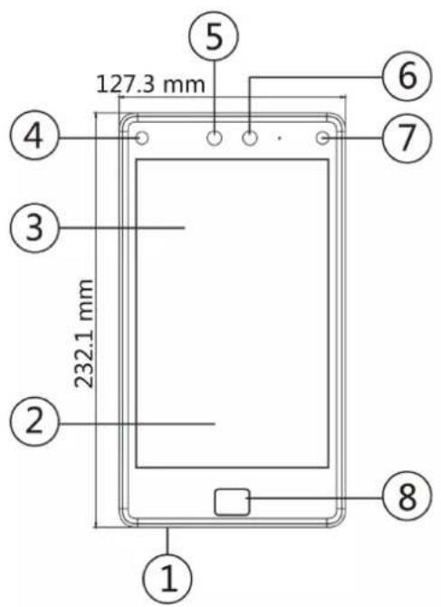
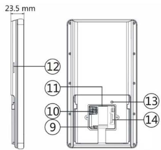
Figure 2-1 Face Recognition Terminal Diagram
Table 2-1 Description of Face Recognition Terminal
| No. Description | |
| 1 microUSB Interface |  USB to micro USB cable is included in the package. USB to micro USB cable is included in the package. |
| 2 Card Presenting Area | |
| 3 Touch Screen | |
| 4 IR Light | |
| 5 Camera | |
| 6 Camera | |
| 7 IR Light | |
| 8 Fingerprint Module | |
| 9 Debugging Port | |
| 10 microSIM Card Slot | |
| 11 Network Interface |  If the device supports PoE, the network interface supports power supply by PoE.If the device supports power supply by PoE and the network interface is connected, do not wire the power input terminal. If the device supports PoE, the network interface supports power supply by PoE.If the device supports power supply by PoE and the network interface is connected, do not wire the power input terminal. |
| 12 Loudspeaker | |
| 13 TAMPER | |
| 14 Wiring Terminals |
Chapter 3 Installation
3.1 Installation Environment
- Avoid backlight, direct sunlight, and indirect sunlight.
- For better recognition, there should be light source in or near the installation environment.
- If you have to install the device outdoors, you should install a protective shield (optional) for the device.

For details about installation environment, see Tips for Installation Environment.
3.2 Surface Mounting
Steps

The additional force shall be equal to three times the weight of the equipment. The equipment ad its associated mounting means shall remain secure during the installation. After the installation, the equipment, including any associated mounting plate, shall not be damaged.
- According to the datum line on the mounting template, stick the mounting template on the wall or other surfaces, 1.4 meters higher than the ground.
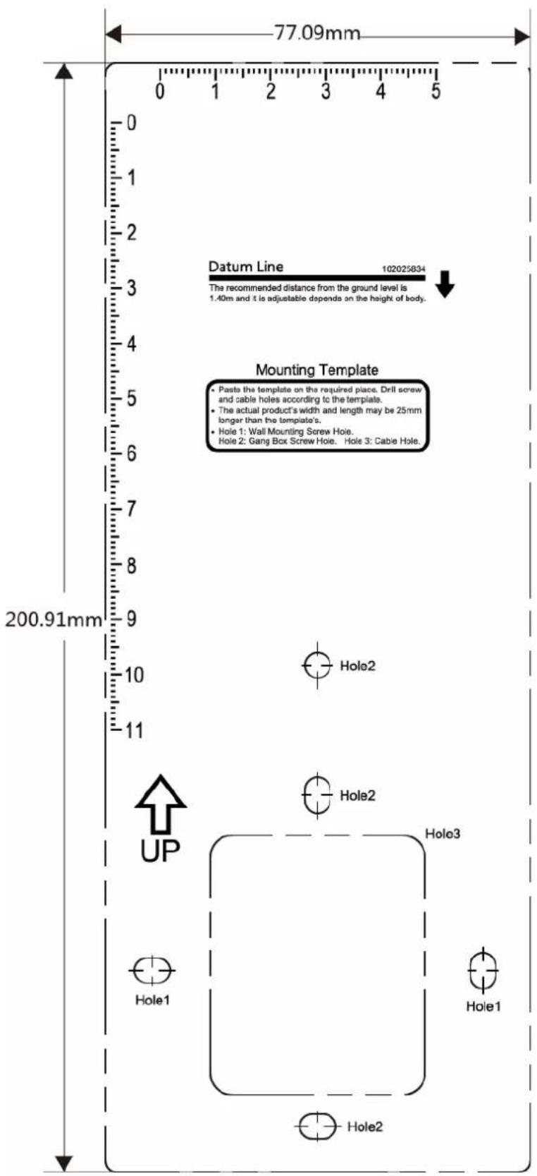
Figure 3-1 Mounting Template
- Drill holes on the wall or other surface according to the Hole 1 and Hole 2 on the mounting template.
- Remove the cable hole on the mounting plate with tools.
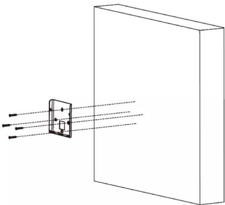
- Align the holes to the mounting plate and secure the mounting plate on the wall with the 4 supplied screws (Pa4×25).
natural_image
Diagram of light rays passing through a rectangular prism onto a rectangular block (no text or symbols)Figure 3-2 Install Mounting Plate
- Route the cable through the cable hole of the mounting plate, and connect to corresponding external devices' cables.
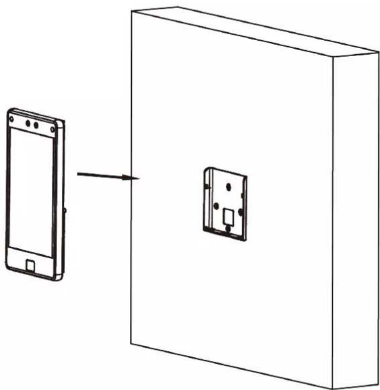
- Align the device with the mounting plate and hang the device on the mounting plate.
natural_image
Diagram showing a smartphone connected to a device inside a rectangular box (no text or symbols)Figure 3-3 Hang Device
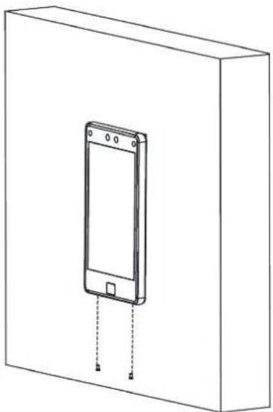
- Use 2 supplied screw (KM3×6) to secure the device and the mounting plate.
natural_image
Line drawing of a smartphone mounted on a rectangular base, with dashed lines indicating hidden edges (no text or symbols)Figure 3-4 Secure Device
- After installation, for the proper use of the device (outdoor use), stick the protection film (parts of models supplied) on the screen.
Chapter 4 Wiring
The device supports connecting to the RS-485 terminal, the door lock, the exit button, the alarm output/input devices, the Wiegand card reader, the access controller, and the power supply. You can wire the peripherals according to the descriptions below.
If connect the Wiegand card reader with the access controller, the face recognition terminal can transmit the authentication information to the access controller and the access controller can judge whether to open the door or not.

Note
- If the cable size is 18 AWG, you should use a 12 V switched-mode power supply. And the distance between the power supply and the device should be no more than 20 m.
- If the cable size is 15 AWG, you should use a 12 V switched-mode power supply. And the distance between the power supply and the device should be no more than 30 m.
- If the cable size is 12 AWG, you should use a 12 V switched-mode power supply. And the distance between the power supply and the device should be no more than 40 m.
4.1 Terminal Description
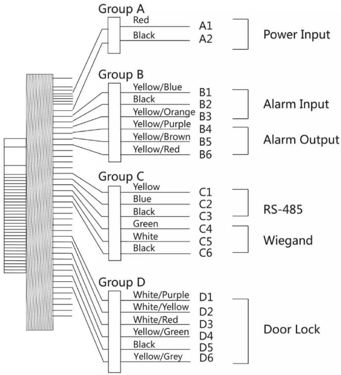
The terminals contains power input, alarm input, alarm output, RS-485, Wiegand output, and door lock.
The terminal's diagram is as follows:
flowchart
graph TD
    subgraph Group_A
        A1["Red"] --> A2["A1"]
        A2 --> B1["Power Input"]
        A2 --> B2["A2"]
        A2 --> B3["Group B"]
        B1 --> B1a["B1"]
        B1 --> B1b["B2"]
        B1 --> B1c["B3"]
        B1 --> B1d["B4"]
        B1 --> B1e["B5"]
        B1 --> B1f["B6"]
        B2 --> B2a["B2"]
        B2 --> B2b["B3"]
        B2 --> B2c["B4"]
        B2 --> B2d["B5"]
        B2 --> B2e["B6"]
    end

    subgraph Group_B
        B3["Yellow/Blue"] --> B4["B1"]
        B3 --> B4a["B2"]
        B3 --> B4b["B3"]
        B3 --> B4c["B4"]
        B3 --> B4d["B5"]
        B3 --> B4e["B6"]
        B4 --> B4a
        B4a --> B4b
        B4b --> B4c
        B4c --> B4d
        B4d --> B4e
        B4e --> B4f["B5"]
        B4f --> B4g["B6"]
    end

    subgraph Group_C
        C1["Yellow"] --> C2["C1"]
        C1 --> C2a["C2"]
        C1 --> C2b["C3"]
        C1 --> C2c["C4"]
        C1 --> C2d["C5"]
        C1 --> C2e["C6"]
        C2 --> C2a
        C2a --> C2b
        C2b --> C2c
        C2c --> C2d
        C2d --> C2e
        C2e --> C2f
        C2f --> C2g
        C2g --> C2h
        C2h --> C2i
        C2i --> C2j
        C2j --> C2k
        C2k --> C2l
        C2l --> C2m
        C2m --> C2n
        C2n --> C2o
        C2o --> C2p
        C2p --> C2q
        C2q --> C2r
        C2r --> C2w
        C2w --> C2x
        C2x --> C2y
        C2y --> C2z
        C2z --> C2w
    end

    subgraph Group_D
        D1["White/Purple"] --> D1a["D1"]
        D1 --> D1b["D2"]
        D1 --> D1c["D3"]
        D1 --> D1d["D4"]
        D1 --> D1e["D5"]
        D1 --> D1f["D6"]
    end

    Group_D --> R["SRS-485"]
    Group_D --> W["Wiegand"]
    Group_D --> Door_Lock["Door Lock"]
Figure 4-1 Terminal Diagram
The descriptions of the terminals are as follows:
Table 4-1 Terminal Descriptions
| Group No. | FunctionColor Name Description | ||||
| Group A A1 Power | Power Input Red +12 | ~ 24 VDC Power | Supply | ||
| A2 Black GND G | round | ||||
| Group B | B1 | Alarm Input | Yellow/Blue | IN1 | Alarm Input 1 |
| B2 Black GND Ground | |||||
| B3 Yellow/Orange | In2 Alarm Input 2 | ||||
| B4 Alarm Output | Yellow/Purple | NC Alarm Output | Wiring | ||
| B5 Yellow/Brown COM | |||||
| B6 Yellow/Red | NO | ||||
| Group C | C1 | RS-485 | Yellow | 485+ | RS-485 Wiring |
| C2 Blue | 485- | ||||
| C3 Black GND Ground | |||||
| C4 Wiegand Green | WO | Wiegand | Wiring 0 | ||
| C5 White | W1 Wiegand | Wiring 1 | |||
| C6 Black GND Ground | |||||
| Group D | D1 | Door Lock | White/Purple | NC | Lock Wiring (NC) |
| D2 | White/Yellow | COM Common | |||
| D3 | White/Red | NO | Lock Wiring (NO) | ||
| D4 | Yellow/Green | SENSOR | Door Contact | ||
| D5 | Black GND Ground | ||||
| D6 | Yellow/Gray | BTN | Exit Door Wiring | ||
4.2 Wire Normal Device
You can connect the terminal with normal peripherals.
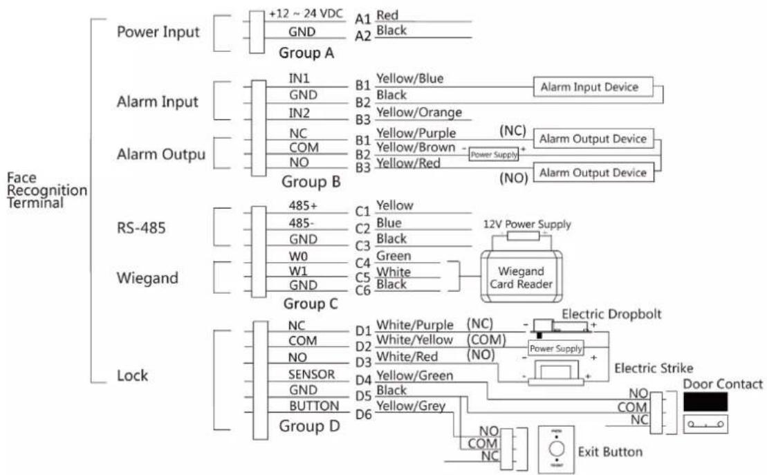
flowchart
graph TD
    A["Face Recognition Terminal"] --> B["Power Input"]
    B --> C["+12 ~ 24 VDC"]
    B --> D["GND"]
    B --> E["A1 Red"]
    B --> F["A2 Black"]
    B --> G["Group A"]
    H["Alarm Input"] --> I["IN1"]
    H --> J["GND"]
    H --> K["IN2"]
    H --> L["NC"]
    H --> M["COM"]
    H --> N["NO"]
    H --> O["Group B"]
    P["Alarm Output"] --> Q["Yellow/Blue"]
    P --> R["Black"]
    P --> S["Yellow/Orange"]
    P --> T["Yellow/Purple (NC)"]
    P --> U["Yellow/Brown - Power Supply +"]
    P --> V["Yellow/Red (NO)"]
    P --> W["Group C"]
    X["RS-485"] --> Y["485+"]
    X --> Z["485-"]
    X --> AA["GND"]
    X --> AB["C3 Black"]
    X --> AC["W0"]
    X --> AD["C4 Green"]
    X --> AE["W1"]
    X --> AF["C5 White"]
    X --> AG["C6 Black"]
    X --> AH["Group C"]
    AI["Wiegand"] --> AJ["Group C"]
    AK["Lock"] --> AL["NC"]
    AK --> AM["COM"]
    AK --> AN["NO"]
    AK --> AO["SENSOR"]
    AK --> AP["GND"]
    AK --> AQ["BUTTON"]
    AK --> AR["Group D"]

    subgraph Legend
        S1["White/Purple (NC)"]
        S2["White/Yellow (COM)"]
        S3["White/Red (NO)"]
        S4["Yellow/Green"]
        S5["Black"]
        S6["Yellow/Grey"]
        S7["NO"]
        S8["COM"]
        S9["NC"]
        S10["Exit Button"]
        S11["Electric Dropbolt"]
        S12["Power Supply +"]
        S13["Electric Strike"]
        S14["NO"]
        S15["COM"]
        S16["NC"]
        S17["Door Contact"]
    end
Figure 4-2 Device Wiring

Note
- You should set the face recognition terminal's Wiegand direction as Input to connect to a Wiegand card reader. If connects to an access controller, you should set the Wiegand direction as Output to transmit authentication information to the access controller.
- For details about Wiegand direction settings, see Set Wiegand Parameters.
- Do not wire the device to the electric supply directly.
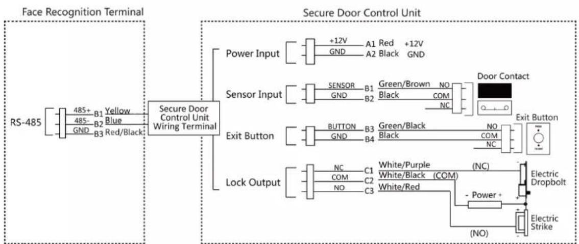
4.3 Wire Secure Door Control Unit
You can connect the terminal with the secure door control unit.
The wiring diagram is as follows.
flowchart
graph TD
    A["RS-485"] --> B["Face Recognition Terminal"]
    B --> C["Secure Door Control Unit Wiring Terminal"]
    C --> D["Power Input"]
    C --> E["Sensor Input"]
    C --> F["Exit Button"]
    C --> G["Lock Output"]
    D --> H["+12V GND A1 Red +12V Black GND"]
    E --> I["SENSOR B1 Green/Brown NO Black COM NC"]
    F --> J["BUTTON B3 Green/Black NO COM NC"]
    G --> K["NC C1 White/Purple (NC) COM C2 White/Black (COM) White/Red"]
    H --> L["Door Contact"]
    I --> M["Exit Button"]
    J --> N["Power + (NO)"]
    K --> O["Electric Dropbolt"]
    L --> P["Electric Strike"]
Figure 4-3 Secure Door Control Unit Wiring

Note
- The secure door control unit should connect to an external power supply separately. The suggested external power supply is 12V, 0.5A.
- For scenarios with high safety requirement, use the secure door control unit wiring first.
- You can ask the technical support to purchase for the secure door control unit separately.
- The picture here are parts of the wiring. For details, see the secure door control unit's user manual.
4.4 Wire Fire Module
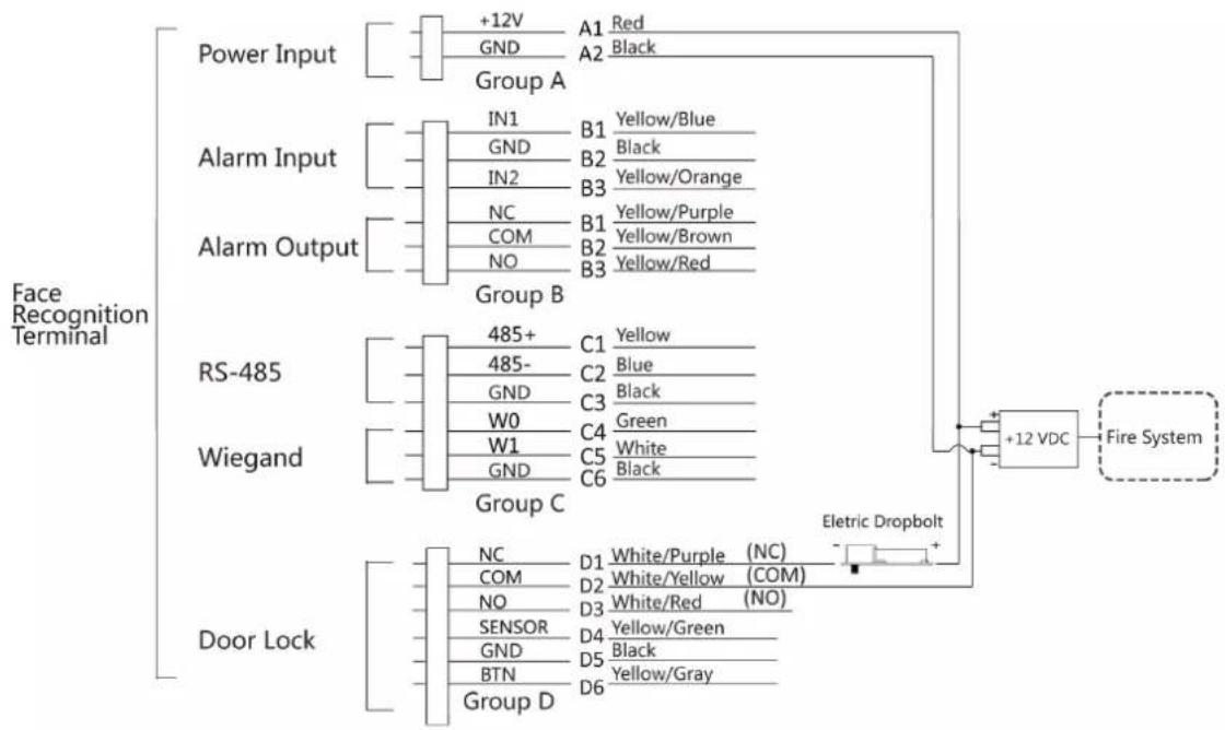
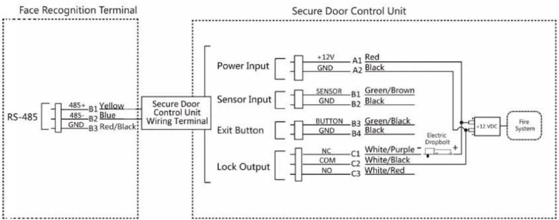
4.4.1 Wiring Diagram of Door Open When Powering Off
Lock Type: Anode Lock, Magnetic Lock, and Electric Bolt (NO)
Security Type: Door Open When Powering Off
Scenario: Installed in Fire Engine Access
Type 1

Note
The fire system controls the power supply of the access control system.
flowchart
graph TD
    A["Power Input"] --> B["+12V"]
    B --> C["GND"]
    C --> D["Group A"]
    E["Alarm Input"] --> F["IN1"]
    F --> G["GND"]
    G --> H["Group B"]
    I["Alarm Output"] --> J["NC"]
    J --> K["COM"]
    K --> L["Group C"]
    M["RS-485"] --> N["485+"]
    N --> O["485-"]
    O --> P["GND"]
    P --> Q["W0"]
    Q --> R["Group C"]
    S["Wiegand"] --> T["W1"]
    T --> U["GND"]
    U --> V["Group C"]
    W["Door Lock"] --> X["NC"]
    X --> Y["COM"]
    Y --> Z["Group D"]
    AA["+12 VDC"] --> AB["Fire System"]
    AC["Eltric Dropbolt"] --> AD["+12 VDC"]
    AE[Red/Blue/Orange/Purple/Brown/Red/Blue/Blue/Black/Blue/Black/Blue/Blue/Blue/Blue/Blue/Blue/Blue/Blue/Blue/Blue/Blue/Blue/Blue/Blue/Blue/Blue/Blue/Blue/Blue/Blue/Blue/Blue/Blue/Blue/Blue/Blue/Blue/Blue/Blue/Blue/Blue/Blue/Blue/Blue/Blue/Blue/Blue/Blue/Blue/Blue/Blue/Blue/Blue/Blue/Blue/Blue/Blue/Blue/Blue/Blue/ Blue/ Green/ White/ Black/ Green/ White/ Red (NO) / White/Purple (NC) / White/Yellow (COM) / White/Yellow (COM) / White/Yellow (COM) / White/Yellow (COM) / White/Yellow (COM) / White/Yellow (COM) / White/Yellow (COM) / White/Yellow (COM) / White/Yellow (COM) / White/Yellow (COM) / White/Yellow (COM) / White/Yellow (COM) / White/Yellow (COM) / White/Yellow (COM) / White/Yellow (COM) - Eltric Dropbolt --> AB
Figure 4-4 Wire Device
flowchart
graph LR
    A["RS-485"] --> B["Face Recognition Terminal"]
    B --> C["Secure Door Control Unit Wiring Terminal"]
    C --> D["Secure Door Control Unit"]
    D --> E["Fire System"]
    subgraph FaceRecognition
        F["485+"] --> G["B1 Yellow"]
        H["485-"] --> I["B2 Blue"]
        J["GND"] --> K["B3 Red/Black"]
    end
    subgraph SecureDoorControlUnit
        L["Power Input"] --> M["+12V"]
        N["GND"] --> O["A1 Red"]
        P["A2 Black"] --> Q["Sensor Input"]
        R["GND"] --> S["B1 Green/Brown"]
        T["B2 Black"] --> U["Sensor Input"]
        V["GND"] --> W["B3 Green/Black"]
        X["B4 Black"] --> Y["Sensor Input"]
    end
    subgraph LockOutput
        Z["NC"] --> AA["C1 White/Purple"]
        AB["COM"] --> AC["C2 White/Black"]
        AD["NO"] --> AE["C3 White/Red"]
    end
    F --> F
    H --> H
    J --> J
    K --> K
    L --> L
    M --> M
    N --> N
    O --> O
    Q --> Q
    S --> S
    U --> U
    V --> V
    W --> W
    X --> X
    Y --> Y
    AA --> AA
    AC --> AC
    AE --> AE
    AE --> AE
    AE --> AE
    AE --> AE
    AE --> AE
    AE --> AE
    AE --> AE
    AE --> AE
    AE --> AE
    AE --> AE
    AE --> AE
    AE --> AE
    AE --> AE
    AE --> AE
    AE --> AE
    AE --> AE
Figure 4-5 Wire Secure Door Control Unit
Type 2

Note
The fire system (NO and COM, normally open when powering off) is connected with the lock and the power supply in series. When an fire alarm is triggered, the door remains open. In normal times, NO and COM are closed.
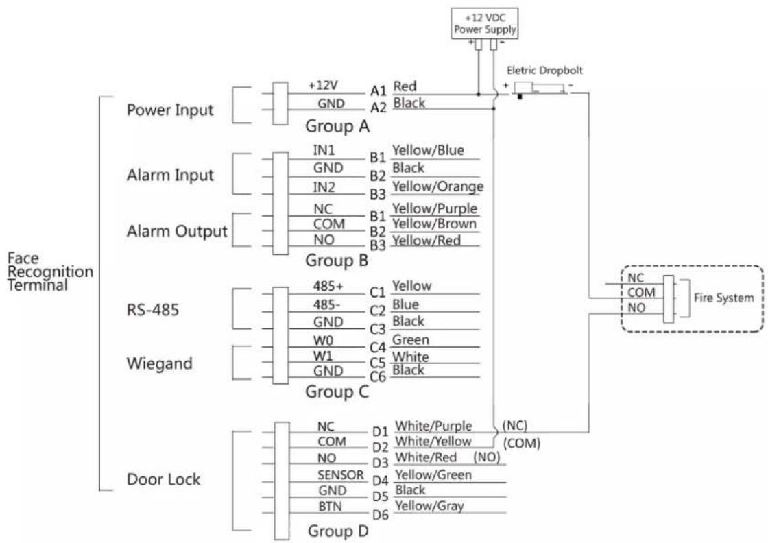
flowchart
graph TD
    A["+12 VDC Power Supply"] --> B["Eltric Dropbolt"]
    C["Power Input"] --> D["Group A"]
    E["Alarm Input"] --> F["Group B"]
    G["Alarm Output"] --> H["Group C"]
    I["RS-485"] --> J["Group C"]
    K["Wiegand"] --> L["Group C"]
    M["Door Lock"] --> N["Group D"]
    O["Fire System"] --> P["+12 VDC Power Supply"]
    Q["+12 VDC Power Supply"] --> R["+12 VDC Power Supply"]
    S["+12 VDC Power Supply"] --> T["+12 VDC Power Supply"]
    U["+12 VDC Power Supply"] --> V["+12 VDC Power Supply"]
    W["+12 VDC Power Supply"] --> X["+12 VDC Power Supply"]
    Y["+12 VDC Power Supply"] --> Z["+12 VDC Power Supply"]
    AA["+12 VDC Power Supply"] --> AB["+12 VDC Power Supply"]
    AC["+12 VDC Power Supply"] --> AD["+12 VDC Power Supply"]
    AE["+12 VDC Power Supply"] --> AF["+12 VDC Power Supply"]
    AG["+12 VDC Power Supply"] --> AH["+12 VDC Power Supply"]
    AI["+12 VDC Power Supply"] --> AJ["+12 VDC Power Supply"]
    AK["+12 VDC Power Supply"] --> AL["+12 VDC Power Supply"]
    AM["+12 VDC Power Supply"] --> AN["+12 VDC Power Supply"]
    AO["+12 VDC Power Supply"] --> AP["+12 VDC Power Supply"]
    AQ["+12 VDC Power Supply"] --> AR["+12 VDC Power Supply"]
    AS["+12 VDC Power Supply"] --> AT["+12 VDC Power Supply"]
    AU["+12 VDC Power Supply"] --> AV["+12 VDC Power Supply"]
    AW["+12 VDC Power Supply"] --> AX["+12 VDC Power Supply"]
    AY["+12 VDC Power Supply"] --> AZ["A1 Red Black"]
    BA["+12 VDC Power Supply"] --> BB["A2 Black"]
    BC["+12 VDC Power Supply"] --> BD["A3 Black"]
    BE["+12 VDC Power Supply"] --> BF["A4 Black"]
    BG["+12 VDC Power Supply"] --> BH["A5 Black"]
    BI["+12 VDC Power Supply"] --> BJ["A6 Black"]
    BK["+12 VDC Power Supply"] --> BL["A7 Black"]
    BM["+12 VDC Power Supply"] --> BN["A8 Black"]
    BO["+12 VDC Power Supply"] --> BP["A9 Black"]
    BQ["+12 VDC Power Supply"] --> BR["A10 Black"]
    BS["+12 VDC Power Supply"] --> BT["A11 Black"]
    BU["+12 VDC Power Supply"] --> BV["A12 Black"]
    BW["+12 VDC Power Supply"] --> BX["A13 Black"]
    BY["+12 VDC Power Supply"] --> BZ["A14 Black"]
    CA["+12 VDC Power Supply"] --> CB["A15 Black"]
    CC["+12 VDC Power Supply"] --> CD["A16 Black"]
    DJ["+12 VDC Power Supply"] --> DE["A17 Black"]
    FD["+12 VDC Power Supply"] --> FD0["+12 VDC Power Supply"]
    DG["+12 VDC Power Supply"] --> DG0["+12 VDC Power Supply"]
    DH["+12 VDC Power Supply"] --> DH0["+12 VDC Power Supply"]
    DI["+12 VDC Power Supply"] --> DJ0["+12 VDC Power Supply"]
    DJ0 --> DJ00["+12 VDC Power Supply"]
    DK["+12 VDC Power Supply"] --> DL0["+12 VDC Power Supply"]
    DL0 --> DL00["+12 VDC Power Supply"]
    DW["+12 VDC Power Supply"] --> DW0["+12 VDC Power Supply"]
    DX["+12 VDC Power Supply"] --> DX0["+12 VDC Power Supply"]
    DX0 --> DX00["+12 VDC Power Supply"]
    DX00 --> DX000["+12 VDC Power Supply"]
    DX000 --> DX0000["+12 VDC Power Supply"]
Figure 4-6 Wiring Device
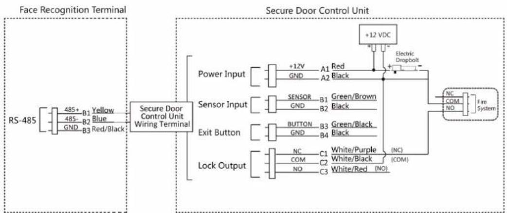
flowchart
graph LR
    A["RS-485"] --> B["Face Recognition Terminal"]
    B --> C["Secure Door Control Unit Wiring Terminal"]
    C --> D["Secure Door Control Unit"]
    D --> E["Power Input"]
    D --> F["Sensor Input"]
    D --> G["Exit Button"]
    D --> H["Lock Output"]
    E --> I["+12V"]
    E --> J["GND"]
    E --> K["A1"]
    E --> L["A2"]
    F --> M["SENSOR"]
    F --> N["GND"]
    F --> O["B1"]
    F --> P["B2"]
    G --> Q["BUTTON"]
    G --> R["GND"]
    G --> S["B3"]
    G --> T["B4"]
    H --> U["NC"]
    H --> V["COM"]
    H --> W["C2"]
    H --> X["NO"]
    H --> Y["C3"]
    H --> Z["White/Purple (NC)"]
    H --> AA["White/Black (COM)"]
    H --> AB["White/Red (NO)"]
    D --> AC["+12 VDC"]
    AC --> AD["Electric Dropbolt"]
    AD --> AE["Fire System"]
Figure 4-7 Wiring Secure Door Control Unit
4.4.2 Wiring Diagram of Door Locked When Powering Off
Lock Type: Cathode Lock, Electric Lock, and Electric Bolt (NC)
Security Type: Door Locked When Powering Off
Scenario: Installed in Entrance/Exit with Fire Linkage

Note
- The Uninterpretable Power Supply (UPS) is required.
- The fire system (NC and COM, normally closed when powering off) is connected with the lock and the power supply in series. When an fire alarm is triggered, the door remains open. In normal times, NC and COM are open.
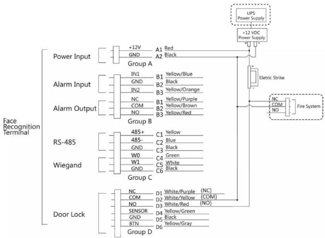
flowchart
graph TD
    A["Power Input"] --> B["+12V GND Group A"]
    C["Alarm Input"] --> D["IN1 GND IN2 NC COM NO"]
    E["Alarm Output"] --> F["Group B"]
    G["RS-485"] --> H["485+ 485- GND W0 W1 GND"]
    I["Wiegand"] --> J["Group C"]
    K["Door Lock"] --> L["Group D"]
    M["UPS Power Supply"] --> N["+12 VDC Power Supply"]
    O["Eltric Strike"] --> P["Fire System"]
    Q["NC COM NO"] --> R["Fire System"]
    S["White/Purple (NC) White/Yellow (COM) White/Red (NO)"] --> T["Group C"]
    U["Yellow/Blue Black Yellow/Orange Yellow/Purple Yellow/Brown Yellow/Red"] --> V["Group B"]
    W["Green White Black Green"] --> X["Group C"]
    Y["Black Black"] --> Z["Group D"]
Figure 4-8 Device Wiring
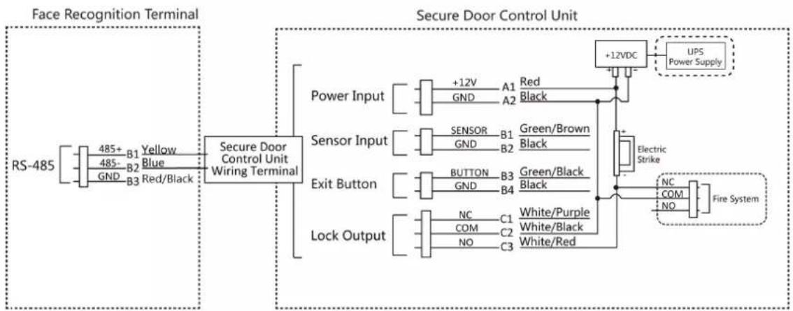
flowchart
graph LR
    subgraph_FaceRecognition["Terminal"]
        A["RS-485"] --> B["485+ B1 Yellow"]
        A --> C["485- B2 Blue"]
        A --> D["GND B3 Red/Black"]
    end

    subgraph_SecureDoorControlUnit["Secure Door Control Unit Wiring Terminal"]
        E["Power Input"] --> F["+12V GND A1 Red Black"]
        G["Sensor Input"] --> H["SENSOR GND B1 Green/Brown Black"]
        I["Exit Button"] --> J["BUTTON GND B3 Green/Black Black"]
        K["Lock Output"] --> L["NC COM C1 White/Purple White/Black White/Red"]
    end

    F --> M["+12VDC"]
    H --> M
    J --> M
    L --> M
    M --> N["UPS Power Supply"]
    M --> O["Electric Strike"]
    O --> P["NC COM NO Fire System"]
Figure 4-9 Wiring Diagram
Chapter 5 Activation
You should activate the device before the first login. After powering on the device, the system will switch to Device Activation page.
Activation via the device, SADP tool and the client software are supported.
The default values of the device are as follows:
• The default IP address: 192.0.0.64
• The default port No.: 8000
• The default user name: admin
5.1 Activate via Device
If the device is not activated, you can activate the device after it is powered on.
On the Activate Device page, create a password and confirm the password. Tap Activate and the device will activated.
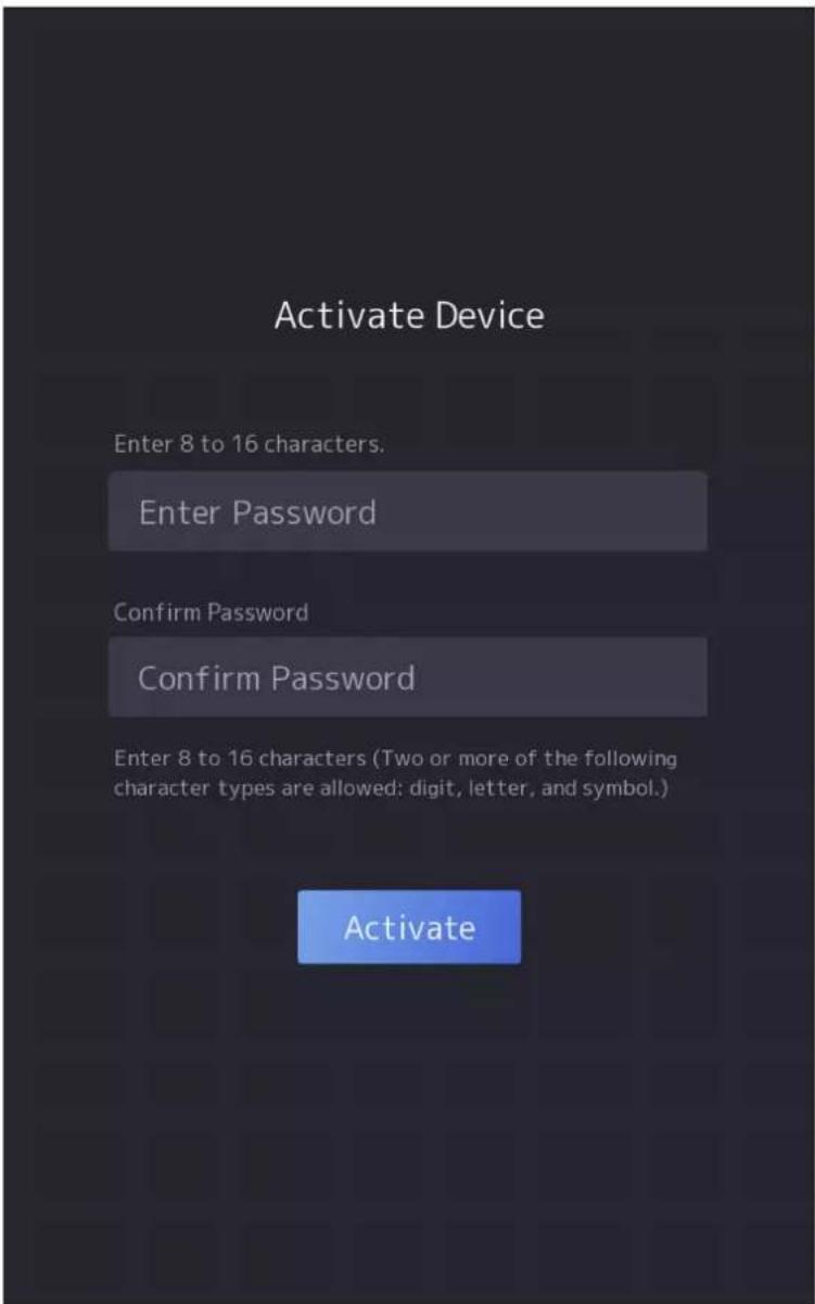
Figure 5-1 Activation Page

Caution
The password strength of the device can be automatically checked. We highly recommend you change the password of your own choosing (using a minimum of 8 characters, including at least three kinds of following categories: upper case letters, lower case letters, numbers, and special characters) in order to increase the security of your product. And we recommend you change your password regularly, especially in the high security system, changing the password monthly or weekly can better protect your product.
Proper configuration of all passwords and other security settings is the responsibility of the installer and/or end-user.

Note
Characters containing admin and nimda are not supported to be set as activation password.
After activation, you should select language, set password change type, set application mode, set network, set platform parameters, set privacy parameters, and set administrator.
5.2 Activate via Web Browser
You can activate the device via the web browser.
Steps
- Enter the device default IP address (192.0.0.64) in the address bar of the web browser, and press Enter.

Note
Make sure the device IP address and the computer's should be in the same IP segment.
- Create a new password (admin password) and confirm the password.

Caution
STRONG PASSWORD RECOMMENDED-We highly recommend you create a strong password of your own choosing (using a minimum of 8 characters, including upper case letters, lower case letters, numbers, and special characters) in order to increase the security of your product. And we recommend you reset your password regularly, especially in the high security system, resetting the password monthly or weekly can better protect your product.
-
Click Activate.
-
Edit the device IP address. You can edit the IP address via the SADP tool, the device, and the client software.
5.3 Activate via SADP
SADP is a tool to detect, activate and modify the IP address of the device over the LAN.
Before You Start
- Get the SADP software from the supplied disk or the official website http://
www.hikvision.com/en/, and install the SADP according to the prompts.
- The device and the PC that runs the SADP tool should be within the same subnet.
The following steps show how to activate a device and modify its IP address. For batch activation and IP addresses modification, refer to User Manual of SADP for details.
Steps
- Run the SADP software and search the online devices.
- Find and select your device in online device list.
- Input new password (admin password) and confirm the password.

Caution
STRONG PASSWORD RECOMMENDED-We highly recommend you create a strong password of your own choosing (using a minimum of 8 characters, including upper case letters, lower case letters, numbers, and special characters) in order to increase the security of your product. And we recommend you reset your password regularly, especially in the high security system, resetting the password monthly or weekly can better protect your product.
- Click Activate to start activation.
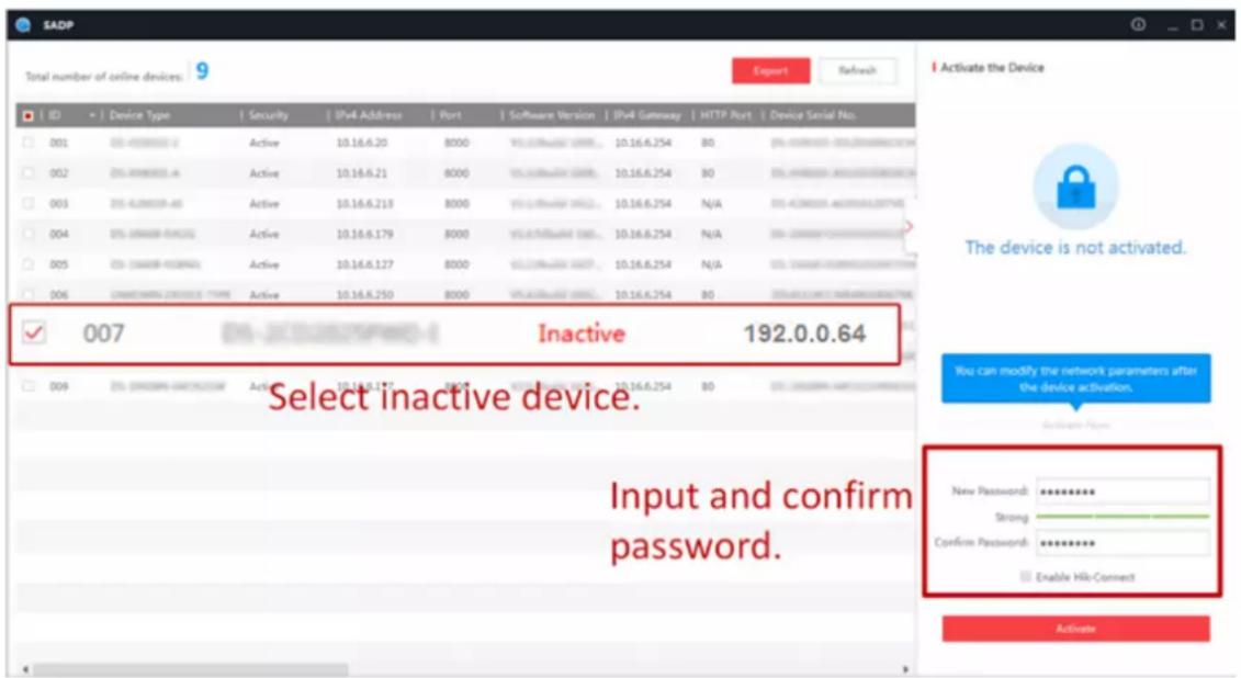
Status of the device becomes Active after successful activation.
- Modify IP address of the device.
1) Select the device.
2) Change the device IP address to the same subnet as your computer by either modifying the IP address manually or checking Enable DHCP.
3) Input the admin password and click Modify to activate your IP address modification.
5.4 Activate Device via Client Software
For some devices, you are required to create the password to activate them before they can be added to the software and work properly.
Steps

Note
This function should be supported by the device.
- Enter the Device Management page.
- Click ▲ on the right of Device Management and select Device.
- Click Online Device to show the online device area.
The searched online devices are displayed in the list.
- Check the device status (shown on Security Level column) and select an inactive device.
- Click Activate to open the Activation dialog.
- Create a password in the password field, and confirm the password.

Caution
The password strength of the device can be automatically checked. We highly recommend you change the password of your own choosing (using a minimum of 8 characters, including at least three kinds of following categories: upper case letters, lower case letters, numbers, and special characters) in order to increase the security of your product. And we recommend you change your password regularly, especially in the high security system, changing the password monthly or weekly can better protect your product.
Proper configuration of all passwords and other security settings is the responsibility of the installer and/or end-user.
- Click OK to activate the device.
Chapter 6 Quick Operation
6.1 Select Language
You can select a language for the device system.
After the device activation, you can select a language for the device system.
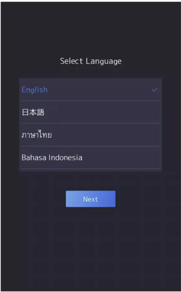
Figure 6-1 Select System Language
6.2 Set Password Change Type
After activating the device, you can set the password change type as reserved email address or security questions. Once you forgot the device password, you can change the password via the selected change type.
Change Password via Email Address
If you need to change password via reserved email, you can enter an email address, and tap Next.
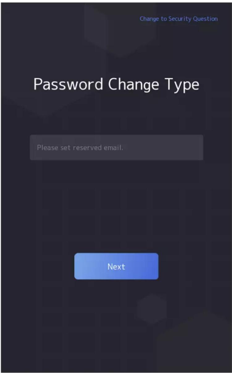
Figure 6-2 Password Change Page
Change via Security Questions
If you need to change password via security questions, you can tap Change to Security Questions on the right corner. Select the security questions and enter the answers. Click Next.

You can only select one type to change password. If you need, you can enter the web page to set both of the changing types.
6.3 Set Network Parameters
You can set the network for the device.
Steps

Parts of the device models supports wi-fi function. Refers to the actual device for details.
- When you enter the Select Network page, tap Wired Network or Wi-Fi for your actual needs.
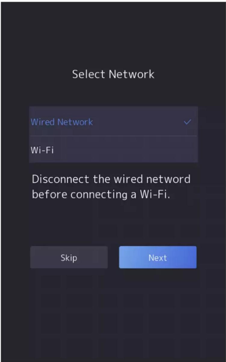
Figure 6-3 Select Network

Note
Disconnect the wired network before connecting a Wi-Fi.
2. Tap Next.
Wired Network

Note
Make sure the device has connected to a network.
If enable DHCP, the system will assign the IP address and other parameters automatically.
If disable DHCP, you should set the IP address, the subnet mask, and the gateway.

IP address of 192.168.1.64, and 192.168.1.7 are not suggested to use.
Wi-Fi
Select a Wi-Fi and enter the Wi-Fi's password to get connected.
Or tap Add Wi-Fi and enter the Wi-Fi's name and the password to get connected.
- Optional: Tap Skip to skip network settings.
6.4 Access to Platform
Enable the function and the device can communicate via Hik-Connect. You can add the device to Hik-Connect mobile client and so on.
Steps

Parts of the device models supports function. Refers to the actual device for details.
- Enable Access to Hik-Connect, and set the server IP and verification code.
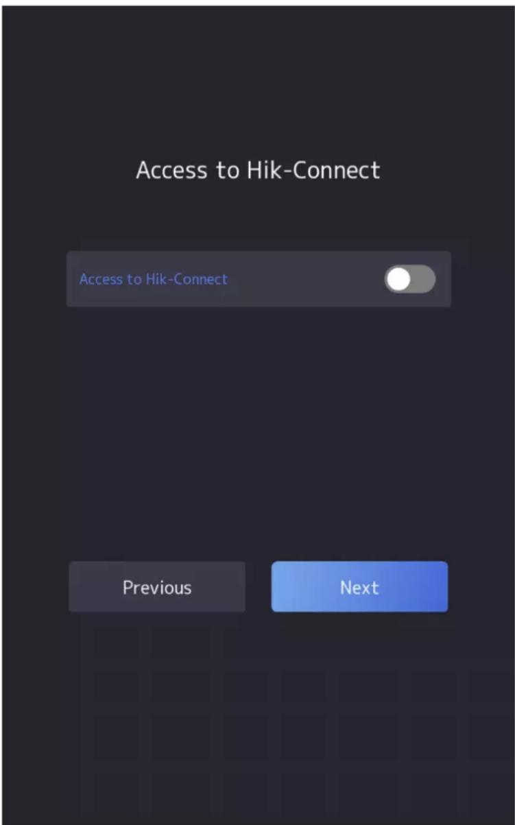
Figure 6-4 Access to Hik-Connect
- Tap Next.
- Optional: Tap Skip to skip the step.
- Optional: Tap Previous to go to the previous page.

Note
If you tap Previous to return to the Wi-Fi configuration page, you need to tap the connected Wi-Fi or connect another Wi-Fi to enter the platform page again.
6.5 Privacy Settings
After activation, selecting application mode, and selecting network, you should set the privacy parameters, including the picture uploading and storage.
Select parameters according to your actual needs.
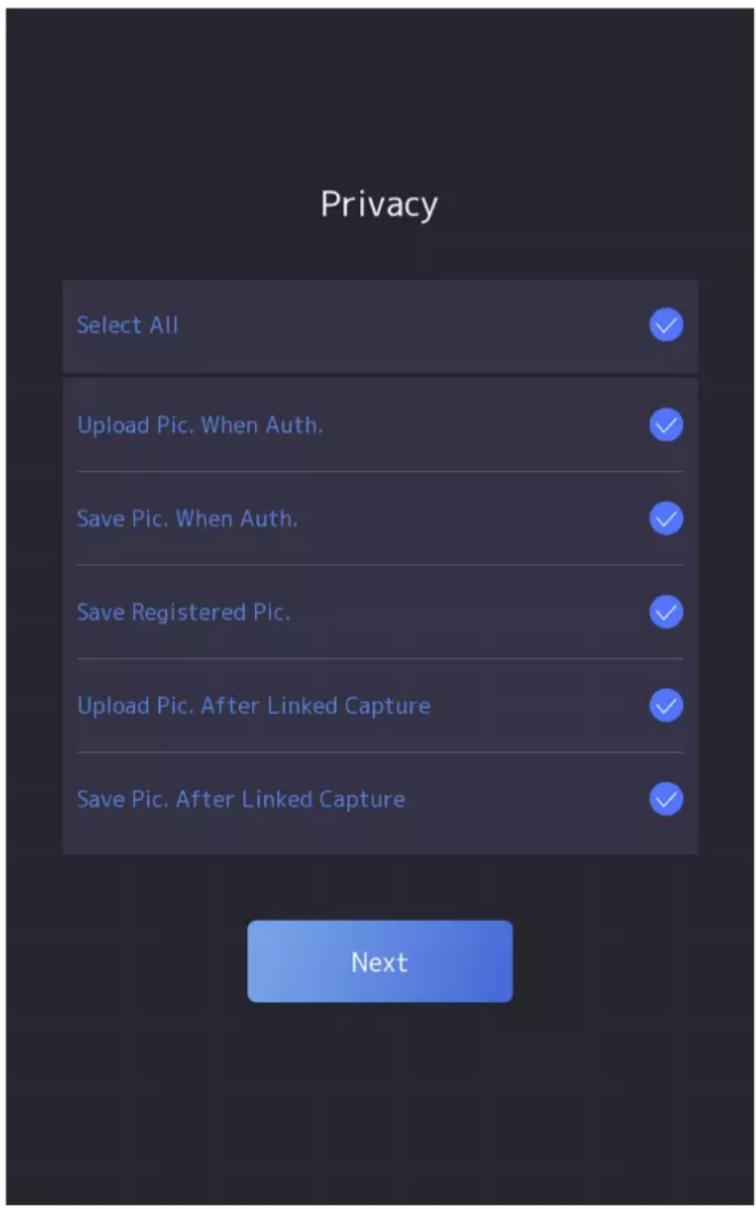
Figure 6-5 Privacy
Upload Captured Pic. When Auth. (Upload Captured Picture When Authenticating)
Upload the pictures captured when authenticating to the platform automatically.
Save Captured Pic. When Auth. (Save Captured Picture When Authenticating)
If you enable this function, you can save the picture when Authenticating to the device.
Save Registered Pic. (Save Registered Picture)
The registered face picture will be saved to the system if you enable the function.
Upload Pic. After Linked Capture (Upload Picture After Linked Capture)
Upload the pictures captured by linked camera to the platform automatically.
Save Pic. After Linked Capture (Save Pictures After Linked Capture)
If you enable this function, you can save the picture captured by linked camera to the device.
Tap Next to complete the settings.
6.6 Set Administrator
After device activation, you can add an administrator to manage the device parameters.
Before You Start
Activate the device and select an application mode.
Steps
-
Optional: Tap Skip to skip adding administrator if required.
-
Enter the administrator's name (optional) and tap Next.
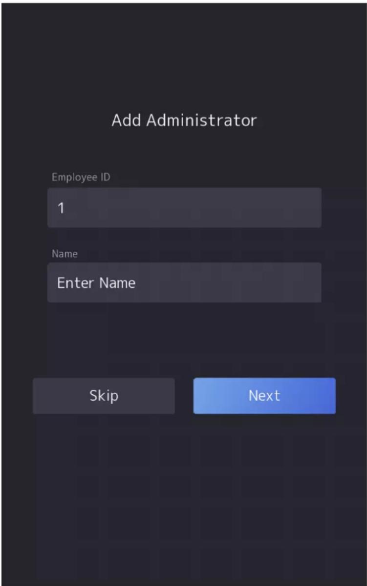
Figure 6-6 Add Administrator Page
- Select a credential to add.

Note
Up to one credential should be added.
- 📷: Face forward at the camera. Make sure the face is in the face recognition area. Click 🔒 to capture and click 🔒 to confirm.
- 📋: Press your finger according to the instructions on the device screen. Click √ to confirm.
-
: Enter the card No. or present card on the card presenting area. Click OK.
-
Click OK.
You will enter the authentication page.
Chapter 7 Basic Operation
7.1 Login
Login the device to set the device basic parameters.
7.1.1 Login by Administrator
If you have added an administrator for the device, only the administrator can login the device for device operation.
Steps
- Long tap on the initial page for 3 s and slide to the left/right by following the gesture to enter the admin login page.
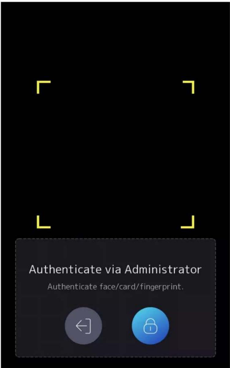
Figure 7-1 Admin Login
- Authenticate the administrator's face, fingerprint or card to enter the home page.
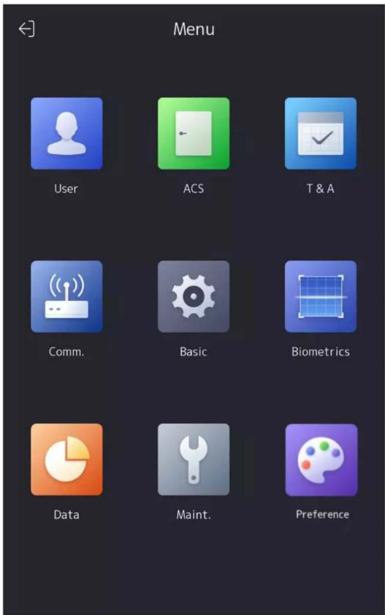
Figure 7-2 Home Page

Note
The device will be locked for 30 minutes after 5 failed fingerprint or card attempts.
- Optional: Tap and you can enter the device activation password for login.
- Optional: Tap and you can exit the admin login page.
7.1.2 Login by Activation Password
You should login the system before other device operations. If you do not configure an administrator, you should follow the instructions below to login.
Steps
-
Long tap on the initial page for 3 s and slide to the left/right by following the gesture to enter password entering page.
-
Enter the password.
-
If you have added an administrator for the device, tap and enter the password.
-
If you haven't added an administrator for the device, enter the password.
-
Tap OK to enter the home page.

Note
The device will be locked for 30 minutes after 5 failed password attempts.
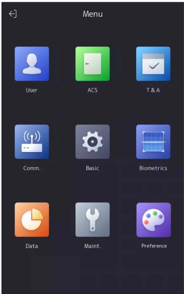
Figure 7-3 Home Page
7.1.3 Forgot Password
If you forget the password during authentication, you can change the password.
Steps
- Hold the initial page for 3 s and slide to the left/right by following the gesture and log in the page.
- Optional: If you have set an administrator, tap in the pop-up admin authentication page.
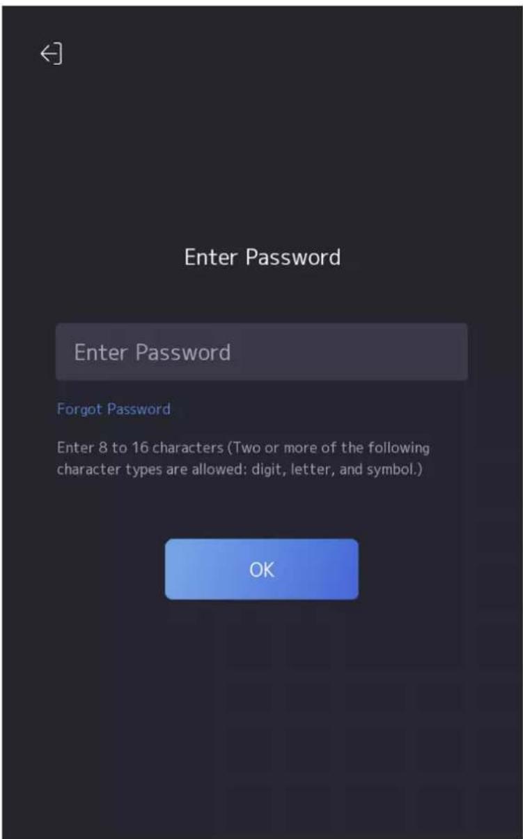
Figure 7-4 Password Authentication Page
3. Tap Forgot Password.
- Select a password change type from the list.

Note
If you have only set 1 password change type, you will go to the corresponded password change page for further settings.
- Answer the security questions or change the password according to email address.
- Security Questions: Answer the security questions that configured when activation.
- Email Address

Make sure the device has added to the Hik-Connect account.
a. Download Hik-Connect app.
b. Go to More → Reset Device Password.
c. Scan the QR code on the device and a verification code will be popped up.

Tap the QR code to get a larger picture.
d. Enter the verification code on the device page.
- Create a new password and confirm it.
- Tap OK.
7.2 Communication Settings
You can set the network parameters, the Wi-Fi parameter, the RS-485 parameters, the Wiegand parameters, and enable 3G/4G on the communication settings page.
7.2.1 Set Wired Network Parameters
You can set the device wired network parameters, including the IP address, the subnet mask, the gateway, and DNS parameters.
Steps
- Tap Comm. (Communication Settings) on the Home page to enter the Communication Settings page.
- On the Communication Settings page, tap Wired Network.
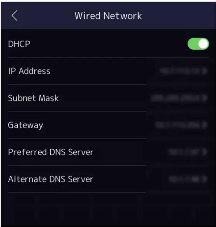
Figure 7-5 Wired Network Settings
-
Set IP Address, Subnet Mask, and Gateway.
-
Enable DHCP, and the system will assign IP address, subnet mask, and gatewayautomatically.
- Disable DHCP, and you should set the IP address, subnet mask, and gateway manually.

-
The device's IP address and the computer IP address should be in the same IP segment.
• IP address of 192.168.1.64, and 192.168.1.7 are not suggested to use. -
Set the DNS parameters. You can enable Auto Obtain DNS, set the preferred DNS server and the alternate DNS server.
7.2.2 Set Wi-Fi Parameters
You can enable the Wi-Fifunction and set the Wi-Fi related parameters.
Steps

The function should be supported by the device.
- Tap Comm. (Communication Settings) on the Home page to enter the Communication Settings page.
- On the Communication Settings page, tap.
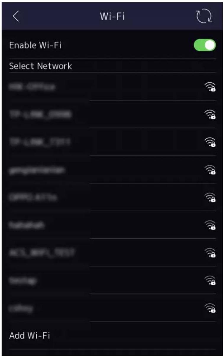
Figure 7-6 Wi-Fi Settings
- Enable the Wi-Fi function.
-
Configure the Wi-Fi parameters.
-
Select a Wi-Fi from the list, and enter the Wi-Fi's password. Tap OK.
- If the target Wi-Fi is not in the list, tap Add Wi-Fi. Enter the Wi-Fi's name and password. And tap OK.

Note
Only digits, letters, and special characters are allowed in the password.
-
Set the Wi-Fi's parameters.
-
By default, DHCP is enable. The system will allocate the IP address, the subnet mask, and the gateway automatically.
-
If disable DHCP, you should enter the IP address, the subnet mask, and the gateway manually.
-
Tap OK to save the settings and go back to the Wi-Fi tab.
-
Tap √ to save the network parameters.
7.2.3 Set RS-485 Parameters
The face recognition terminal can connect external access controller, secure door control unit or card reader via the RS-485 terminal.
Steps
- Tap Comm. (Communication Settings) on the Home page to enter the Communication Settings page.
- On the Communication Settings page, tap RS-485 to enter the RS-485 tab.
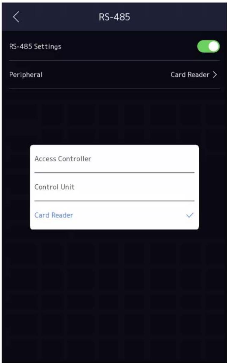
Figure 7-7 Set RS-485 Parameters
- Select an peripheral type according to your actual needs.

Note
If you select Access Controller: If connect the device to a terminal via the RS-485 interface, set the RS-485 address as 2. If you connect the device to a controller, set the RS-485 address according to the door No.
- Tap the back icon at the upper left corner and you should reboot the device if you change the parameters.
7.2.4 Set Wiegand Parameters
You can set the Wiegand transmission direction.
Steps
- Tap Comm. (Communication Settings) on the Home page to enter the Communication Settings page.
- On the Communication Settings page, tap Wiegand to enter the Wiegand tab.
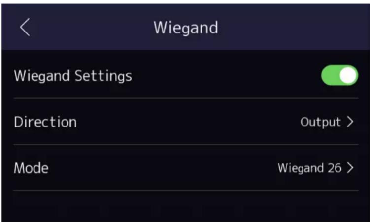
Figure 7-8 Wiegand Settings
- Enable the Wiegand function.
-
Select a transmission direction.
-
Output: A face recognition terminal can connect an external access controller. And the two devices will transmit the card No. via Wiegand 26 or Wiegand 34.
-
Input: A face recognition terminal can connect a Wiegand card reader.
-
Tap to save the network parameters.

Note
If you change the external device, and after you save the device parameters, the device will reboot automatically.
7.2.5 Set ISUP Parameters
Set ISUP parameters and the device can upload data via ISUP protocol.
Before You Start
Make sure your device has connect to a network.
Steps
- Tap Comm. → ISUP.
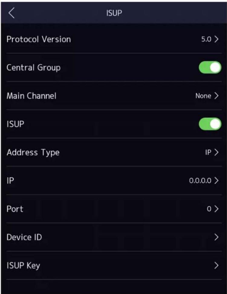
Figure 7-9 ISUP Settings
- Enable the ISUP function and set the ISUP server parameters.
ISUP Version
Set the ISUP version according to your actual needs.
Central Group
Enable central group and the data will be uploaded to the center group.
Main Channel
Support N1 or None.
ISUP
Enable ISUP function and the data will be uploaded via ISUP protocol.
Address Type
Select an address type according to your actual needs.
IP Address
Set the ISUP server's IP address.
Port No.
Set the ISUP server's port No.

Port No. Range: 0 to 65535.
Device ID
Set device serial no.
ISUP Key
If you choose V5.0, you should create an account and ISUP key. If you choose other version, you should create an ISUP account only.

- Remember the ISUP account and ISUP key. You should enter the account name or the key when the device should communicate with other platforms via ISUP protocol.
• ISUP key range: 8 to 32 characters.
7.2.6 Platform Access
You can change the device verification code and set the server address before you add the device to the Hik-Connect mobile client.
Before You Start
Make sure your device has connected to a network.
Steps

Parts of the device models supports function. Refers to the actual device for details.
- Tap Comm. (Communication Settings) on the Home page to enter the Communication Settings page.
- On the Communication Settings page, tap Access to Hik-Connect.
- Enable Access to Hik-Connect
- Enter Server IP.
- Create the Verification Code, and you need to enter the verification code when you manage the devices via Hik-Connect.
7.3 User Management
On the user management interface, you can add, edit, delete and search the user.
7.3.1 Add Administrator
The administrator can log in the device backend and configure the device parameters.
Steps
- Long tap on the initial page and log in the backend.
- Tap User → + to enter the Add User page.
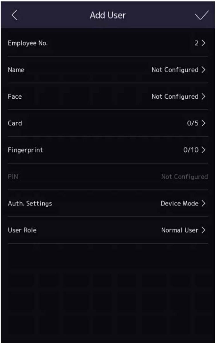
- Edit the employee ID.
i Note
- The employee ID should be less than 32 characters. And it can be a combination of lower letters, upper letters, and numbers.
-
The employee ID should not be duplicated.
-
Tap the Name field and input the user name on the soft keyboard.
i Note
- Numbers, upper case letters, lower case letters, and special characters are allowed in the user name.
-
Up to 32 characters are allowed in the user name.
-
Optional: Add a face picture, fingerprints, or cards for the administrator.
i Note
-
For details about adding a face picture, see Add Face Picture.
• i Note
For details about adding a fingerprint, see Add Fingerprint.
• For details about adding a card, see Add Card. -
Optional: Set the administrator's authentication type.
i Note
For details about setting the authentication type, see Set Authentication Mode.
- Enable the Administrator Permission function.
Enable Administrator Permission
The user is the administrator. Except for the normal attendance function, the user can also enter the Home page to operate after authenticating the permission.
- Tap to save the settings.
7.3.2 Add Face Picture
Add user's face picture to the device. And the user can use the face picture to authenticate.
Steps
- Long tap on the initial page for 3 s and slide to the left/right by following the gesture and log in the backend.
- Tap User → + to enter the Add User page.
- Edit the employee ID.

Note
- The employee ID should be less than 32 characters. And it can be a combination of lower letters, upper letters, and numbers.
-
The employee ID should not be duplicated.
-
Tap the Name field and input the user name on the soft keyboard.

Note
- Numbers, upper case letters, lower case letters, and special characters are allowed in the user name.
-
The suggested user name should be within 32 characters.
-
Tap the Face Picture field to enter the face picture adding page.
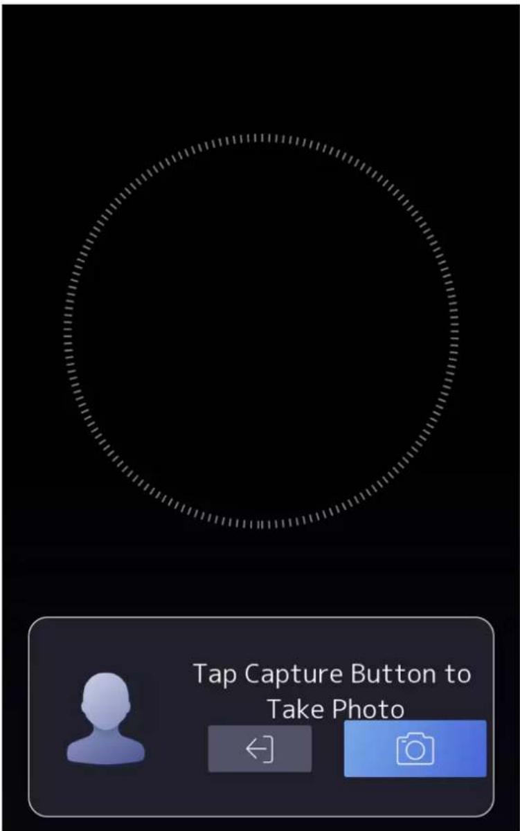
Figure 7-10 Add Face Picture
6. Look at the camera.

Note
• Make sure your face picture is in the face picture outline when adding the face picture.
• Make sure the captured face picture is in good quality and is accurate.
- For details about the instructions of adding face pictures, see Tips When Collecting/Comparing Face Picture.
After completely adding the face picture, a captured face picture will be displayed at the upper right corner of the page.
- Tap Save to save the face picture.
- Optional: Tap Try Again and adjust your face position to add the face picture again.
- Set the user role.
Administrator
The user is the administrator. Except for the normal attendance function, the user can also enter the Home page to operate after authenticating the permission.
Normal User
The User is the normal user. The user can only authenticate or take attendance on the initial page.
- Tap to save the settings.
7.3.3 Add Fingerprint
Add a fingerprint for the user and the user can authenticate via the added fingerprint.
Steps

Note
The function should be supported by the device.
- Long tap on the initial page for 3 s and slide to the left/right by following the gesture and enter the device backend.
- Tap User → + to enter the Add User page.
- Tap the Employee ID. field and edit the employee ID.

Note
- The employee ID should be less than 32 characters. And it can be a combination of lower letters, upper letters, and numbers.
-
The employee ID should not start with 0 and should not be duplicated.
-
Tap the Name field and input the user name on the soft keyboard.

Note
- Numbers, upper case letters, lower case letters, and special characters are allowed in the user name.
-
The suggested user name should be within 32 characters.
-
Tap the Fingerprint field to enter the Add Fingerprint page.
- Follow the instructions to add a fingerprint.

Note
- The same fingerprint cannot be repeatedly added.
- Up to 10 fingerprints can be added for one user.
- You can also use the client software or the fingerprint recorder to record fingerprints.
For details about the instructions of scanning fingerprints, see Tips for Scanning Fingerprint.
- Set the user role.
Administrator
The user is the administrator. Except for the normal attendance function, the user can also enter the Home page to operate after authenticating the permission.
Normal User
The User is the normal user. The user can only authenticate or take attendance on the initial page.
- Tap √ to save the settings.
7.3.4 Add Card
Add a card for the user and the user can authenticate via the added card.
Steps
- Long tap on the initial page for 3 s and slide to the left/right by following the gesture and log in the backend.
- Tap User → + to enter the Add User page.
- Connect an external card reader according to the wiring diagram.
- Tap the Employee ID. field and edit the employee ID.

Note
- The employee ID should be less than 32 characters. And it can be a combination of lower letters, upper letters, and numbers.
-
The employee ID should not be duplicated.
-
Tap the Name field and input the user name on the soft keyboard.

Note
- Numbers, upper case letters, lower case letters, and special characters are allowed in the user name.
-
The suggested user name should be within 32 characters.
-
Tap the Card field and tap +.
-
Configure the card No.
-
Enter the card No. manually.
- Present the card over the card presenting area to get the card No.
i Note
• The card No. cannot be empty.
- Up to 20 characters are allowed in the card No.
• The card No. cannot be duplicated.
-
Configure the card type.
-
Set the user role.
Administrator
The user is the administrator. Except for the normal attendance function, the user can also enter the Home page to operate after authenticating the permission.
Normal User
The User is the normal user. The user can only authenticate or take attendance on the initial page.
- Tap to save the settings.
7.3.5 View Password
Add a password for the user and the user can authenticate via the password.
Steps
- Long tap on the initial page for 3 s and slide to the left/right by following the gesture and log in the backend.
- Tap User → + to enter the Add User page.
- Tap the Employee ID. field and edit the employee ID.
i Note
- The employee ID should be less than 32 characters. And it can be a combination of lower letters, upper letters, and numbers.
-
The employee ID should not be duplicated.
-
Tap the Name field and input the user name on the soft keyboard.
i Note
- Numbers, upper case letters, lower case letters, and special characters are allowed in the user name.
-
The suggested user name should be within 32 characters.
-
Tap the Password to view the password.
i Note
The password cannot be edited. It can only be applied by the platform.
- Set the user role.
Administrator
The user is the administrator. Except for the normal attendance function, the user can also enter the Home page to operate after authenticating the permission.
Normal User
The User is the normal user. The user can only authenticate or take attendance on the initial page.
- Tap to save the settings.
7.3.6 Set Authentication Mode
After adding the user's face picture, password, or other credentials, you should set the authentication mode and the user can authenticate his/her identity via the configured authentication mode.
Steps
- Long tap on the initial page for 3 s and slide to the left/right by following the gesture and log in the backend.
- Tap User → Add User/Edit User → Authentication Mode.
- Select Device or Custom as the authentication mode.
Device
If you want to select device mode, you should set the terminal authentication mode in Access Control Settings page first. For details see Setting Access Control Parameters.
Custom
You can combine different authentication modes together according to your actual needs.
- Tap √ to save the settings.
7.3.7 Search and Edit User
After adding the user, you can search the user and edit it.
Search User
On the User Management page, Tap the search area to enter the Search User page. Tap Card on the left of the page and select a search type from the drop-down list. Enter the employee ID, card No., or the user name for search. Tap to search.
Edit User
On the User Management page, select a user from the user list to enter the Edit User page. Follow the steps in User Management to edit the user parameters. Tap √ to save the settings.

Note
The employee ID cannot be edited.
7.4 Data Management
You can delete data, import data, and export data.
7.4.1 Delete Data
Delete user data.
On the Home page, tap Data → Delete Data → User Data. All user data added in the device will be deleted.
7.4.2 Import Data
Steps
-
Plug a USB flash drive in the device.
-
On the Home page, tap Data → Import Data.
-
Tap User Data or Face Data.
-
Enter the created password when you exported the data. If you do not create a password when you exported the data, leave a blank in the input box and tap OK immediately.

Note
- If you want to transfer all user information from one device (Device A) to another (Device B), you should export the information from Device A to the USB flash drive and then import from the USB flash drive to Device B. In this case, you should import the user data before importing the profile photo.
• The supported USB flash drive format is FAT32. - The imported pictures should be saved in the folder (named enroll_pic) of the root directory and the picture's name should be follow the rule below: Card No._Name_Department_Employee ID_Gender.jpg
- If the folder enroll_pic cannot save all imported pictures, you can create another folders, named enroll_pic1, enroll_pic2, enroll_pic3, enroll_pic4, under the root directory.
- The employee ID should be less than 32 characters. It can be a combination of lower letters, upper letters, and numbers. It should not be duplicated, and should not start with 0.
- Requirements of face picture should follow the rules below: It should be taken in full-face view, directly facing the camera. Do not wear a hat or head covering when taking the face picture. The format should be JPEG or JPG. The resolution should be 640 × 480 pixel or more than of 640 × 480 pixel. The picture size should be between 60 KB and 200 KB.
7.4.3 Export Data
Steps
-
Plug a USB flash drive in the device.
-
On the Home page, tap Data → Export Data.
-
Tap Event Data, User Data, or Face Data.
-
Optional: Create a password for exporting. When you import those data to another device, you should enter the password.

Note
- The supported USB flash drive format is DB.
- The system supports the USB flash drive with the storage of 1G to 32G. Make sure the free space of the USB flash drive is more than 512M.
- The exported user data is a DB file, which cannot be edited.
7.5 Identity Authentication
After network configuration, system parameters configuration and user configuration, you can go back to the initial page for identity authentication. The system will authenticate person according to the configured authentication mode.
You can authenticate identity via 1:1 matching or 1:N matching.
1:N Matching
Compare the captured face picture with all face pictures stored in the device.
1: 1 Matching
Compare the captured face picture with the linked face picture.
7.5.1 Authenticate via Single Credential
Set the user authentication type before authentication. For details, see Set Authentication Mode. Authenticate face, fingerprint, card or QR code.
Face
Face forward at the camera and start authentication via face.
Fingerprint
Place the enrolled fingerprint on the fingerprint module and start authentication via fingerprint.
Card
Present the card on the card presenting area and start authentication via card.

Note
The card can be normal IC card, or encrypted card.
QR Code
Put the QR code in front of the device camera to authenticate via QR code.

Note
- Authentication via QR code should be supported by the device.
- The dimension of the recognized QR code picture should be larger than 6cm× 6cm .
Password
Enter the password to authenticate via password.
If authentication completed, a prompt "Authenticated" will pop up.
7.5.2 Authenticate via Multiple Credential
Before You Start
Set the user authentication type before authentication. For details, see Set Authentication Mode.
Steps
- If the authentication mode is Card and Face, Password and Face, Card and Password, Card and Face and Fingerprint, authenticate any credential according to the instructions on the live view page.

Note
- The card can be normal IC card, or encrypted card.
- If the QR Code Scanning function is enabled, you can put the QR code in front of the device camera to authenticate via QR code.
-
The dimension of the recognized QR code picture should be larger than 6cm× 6cm .
-
After the previous credential is authenticated, continue authenticate other credentials.

Note
- For detailed information about scanning fingerprint, see Tips for Scanning Fingerprint.
- For detailed information about authenticating face, see Tips When Collecting/Comparing Face Picture.
If authentication succeeded, the prompt "Authenticated" will pop up.
7.6 Basic Settings
You can set the voice settings, time settings, sleeping (s), language, community No., building No., Unit No., and beauty.
Long tap on the initial page for 3 s and slide to the left/right by following the gesture and login the device home page. Tap Basic.
| Basic Settings | |
| Voice Settings | > |
| Time Settings | > |
| Sleeping (s) | 60 > |
| Select Language | English > |
| Community No. | 1 > |
| Building No. | 1 > |
| Unit No. | 1 > |
| Beauty | Disable > |
Figure 7-11 Basic Settings Page
Voice Settings
You can enable/disable the voice prompt function and adjust the voice volume.

Note
You can set the voice volume between 0 and 10.
Time Settings
Set the time zone, the device time and the DST.
Sleeping (s)
Set the device sleeping waiting time (minute). When you are on the initial page and if you set the sleeping time to 30 min, the device will sleep after 30 min without any operation.

Note
If you set the sleeping time to 0, the device will not enter sleeping mode.
Select Language
Select the language according to actual needs.
Community No.
Set the device installed community No.
Building No.
Set the device installed building No.
Unit No.
Set the device installed unit No.
Beauty
You can enable the beauty function and set the smooth and the whiten parameter. Tap + or - to control the effect strength.

Note
By default, the function is disabled.
7.7 Set Biometric Parameters
You can customize the face parameters to improve the face recognition performance. The configurable parameters includes application mode, face liveness level, face recognition distance, face recognition interval, wide dynamic, face 1:N security level, face 1:1 security level, ECO settings, face with mask detection, hard hat detection, and multiple faces authentication.
Long tap on the initial page for 3 s and login the home page. Tap System → Biometric.
Table 7-1 Face Picture Parameters
| Parameter Description | |
| Face Liveness Level | After enabling face anti-spoofing function, you can set the matching security level when performing live face authentication.  After disabling face anti-spoofing function, there will be spoofing recognition risks. After disabling face anti-spoofing function, there will be spoofing recognition risks. |
| Face Recognition Distance | Set the valid distance between the user and the camera when authenticating. |
| Face Recognition Interval | The time interval between two continuous face recognitions when authenticating.  You can input the number from 1 to 10. You can input the number from 1 to 10. |
| Wide Dynamic It is suggested to enable the WDR function if installing the device outdoors.When there are both very bright and very dark areas simultaneously in the view, you can enable the WDR function to balance the brightness of the whole image and provide clear images with details. | |
Face 1:N Security Level Set the matching threshold when authenticating via 1:N matching mode.The larger the value, the smaller the false accept rate and the larger the false rejection rate.  You are recommended to retain the default value. The adjustment will affect the face misidentification rate and rejection rate. You are recommended to retain the default value. The adjustment will affect the face misidentification rate and rejection rate. | |
Face 1:1 Security Level Set the matching threshold when authenticating via 1:1 matching mode.The larger the value, the smaller the false accept rate and the larger the false rejection rate.  You are recommended to retain the default value. The adjustment will affect the face misidentification rate and rejection rate. You are recommended to retain the default value. The adjustment will affect the face misidentification rate and rejection rate. | |
| ECO SettingsAfter enabling the ECO mode, the device will use the IR camera to authenticate faces in the low light or dark environment. And you can set the ECO mode threshold, ECO mode (1:N), and ECO mode (1:1). | |
| Parameter Description | Option |
| NoteAfter enabling ECO mode, the face will be recognized in weak light or no light environment. After disabling ECO mode, face recognition effect will decline in weak light or no light environment.ECO ThresholdWhen enabling the ECO mode, you can set the ECO mode's threshold. The larger the value, the easier the device entering the ECO mode.ECO Mode (1:1)Set the matching threshold when authenticating via ECO mode 1:1 matching mode. The larger the value, the smaller the false accept rate and the larger the false rejection rate.ECO Mode (1:N)Set the matching threshold when authenticating via ECO mode 1:N matching mode. The larger the value, the smaller the false accept rate and the larger the false rejection rate | |
| Face with Mask Detection | After enabling the face with mask detection, the system will recognize the captured face with mask picture. You can set face with mask & face 1:N level and the strategy.NoteAfter enabling Face with Mask Detection function, recognition effect of people without mask will be influenced.Reminder of WearingIf the person do not wear a face mask when authenticating, the device prompts a notification and the door will open.Must WearIf the person do not wear a face mask when authenticating, the device prompts a notification and the door keeps closed. |
| Hard Hat Detection | After enabling the hard hat detection, you can set the strategy.Reminder of WearingIf the person do not wear the hard hat when authenticating, the device will pop up a prompt and the door will open.Must Wear |
| Parameter Description | |
| If the person do not wear the hard hat when authenticating, the device will pop up a prompt and the door will keep closed.NoneIf the person do not wear a face mask when authenticating, the device will not prompt a notification. | |
7.8 Set Access Control Parameters
You can set the access control permissions, including the functions of authentication mode, enable NFC card, enable M1 card, door contact, open duration (s) and authentication interval (s).
On the Home page, tap ACS (Access Control Settings) to enter the Access Control Settings page. Edit the access control parameters on this page.
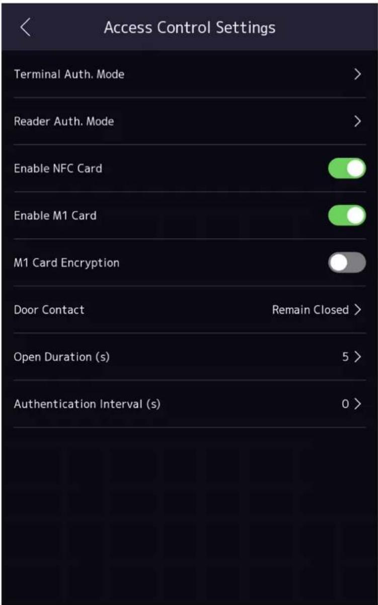
Figure 7-13 Access Control Parameters
The available parameters descriptions are as follows:
Table 7-2 Access Control ParametersDescriptions
| Parameter Description | |
| Terminal Auth. Mode (Terminal Authentication Mode) | Select the face recognition terminal's authentication mode. You can also customize the authentication mode.NoteOnly the device with the fingerprint module supports the fingerprint related function.Biometric recognition products are not completely applicable to anti-spoofing environments. If you require a higher security level, use multiple authentication modes.If you adopt multiple authentication modes, you should authenticate other methods before authenticating face. |
| Reader Auth. Mode (Card Reader Authentication Mode) | Select the card reader's authentication mode. |
| Enable NFC Card Enable the function and you can present the NFC card to authenticate. In order to prevent the mobile phone from getting the data of the access control, you can disable NFC card to increase the security level of the data. | NoteDisable NFC card cannot completely avoid presenting NFC card. |
| Enable M1 Card Enable the function and you can present the M1 card to authenticate. | |
| Door Contact You can select "Remain Open" or "Remian Closed" according to your actual needs. By default, it is Remian Closed. | |
| Open Duration | Set the door unlocking duration. If the door is not opened for the set time, the door will be locked. Available door locked time range: 1 to 255s. |
| Authentication Interval | Set the device authenticating interval. Available authentication interval range: 0 to 65535. |
7.9 Time and Attendance Status Settings
You can set the attendance mode as check in, check out, break out, break in, overtime in, and overtime out according to your actual situation.
i Note
The function should be used cooperatively with time and attendance function on the client software.
7.9.1 Disable Attendance Mode via Device
Disable the attendance mode and the system will not display the attendance status on the initial page.
Tap T&A Status to enter the T&A Status page.
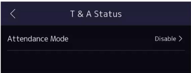
Figure 7-14 Disable Attendance Mode
Set the Attendance Mode as Disable.
You will not view or configure the attendance status on the initial page. And the system will follow the attendance rule that configured on the platform.
7.9.2 Set Manual Attendance via Device
Set the attendance mode as manual, and you should select a status manually when you take attendance.
Before You Start
Add at least one user, and set the user's authentication mode. For details, see User Management.
Steps
- Tap T&A Status to enter the T&A Status page.
- Set the Attendance Mode as Manual.
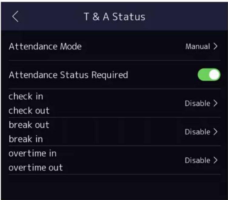
Figure 7-15 Manual Attendance Mode
- Enable the Attendance Status Required.
- Enable a group of attendance status.

The Attendance Property will not be changed.
- Optional: Select an status and change its name if required.
The name will be displayed on the T & A Status page and the authentication result page.
Result
You should select an attendance status manually after authentication.

If you do not select a status, the authentication will be failed and it will not be marked as a valid attendance.
7.9.3 Set Auto Attendance via Device
Set the attendance mode as auto, and you can set the attendance status and its available schedule. The system will automatically change the attendance status according to the configured schedule.
Before You Start
Add at least one user, and set the user's authentication mode. For details, see User Management.
Steps
- Tap T&A Status to enter the T&A Status page.
- Set the Attendance Mode as Auto.
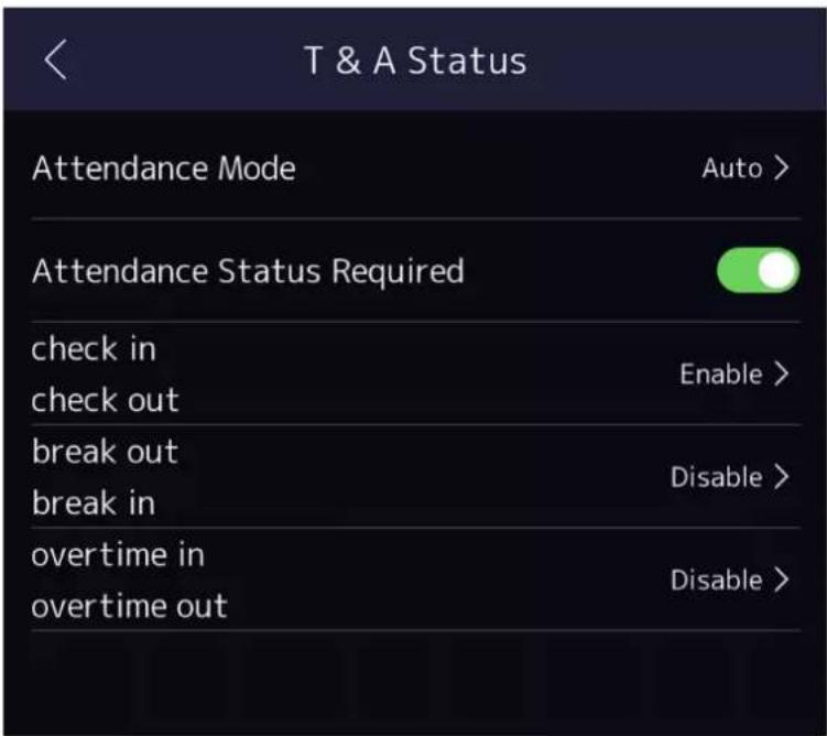
Figure 7-16 Auto Attendance Mode
- Enable the Attendance Status function.
- Enable a group of attendance status.

Note
The Attendance Property will not be changed.
- Optional: Select an status and change its name if required.
The name will be displayed on the T & A Status page and the authentication result page.
- Set the status' schedule.
1) Tap Attendance Schedule.
2) Select Monday, Tuesday, Wednesday, Thursday, Friday, Saturday, or Sunday.
3) Set the selected attendance status's start time of the day.
4) Tap Confirm.
5) Repeat step 1 to 4 according to your actual needs.

Note
The attendance status will be valid within the configured schedule.
Result
When you authenticate on the initial page, the authentication will be marked as the configured attendance status according to the configured schedule.
Example
If set the Break Out as Monday 11:00, and Break In as Monday 12:00, the valid user's authentication from Monday 11:00 to 12:00 will be marked as break.
7.9.4 Set Manual and Auto Attendance via Device
Set the attendance mode as Manual and Auto, and the system will automatically change the attendance status according to the configured schedule. At the same time you can manually change the attendance status after the authentication.
Before You Start
Add at least one user, and set the user's authentication mode. For details, see User Management.
Steps
- Tap T&A Status to enter the T&A Status page.
- Set the Attendance Mode as Manual and Auto.
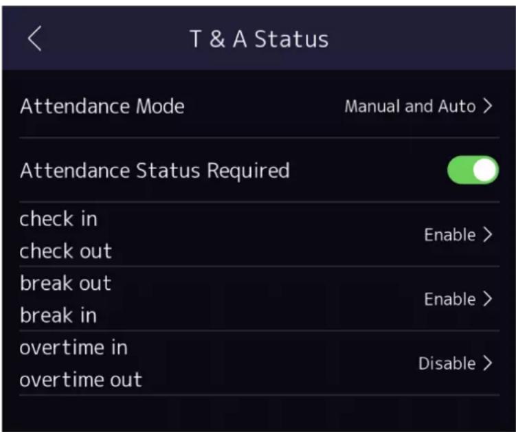
Figure 7-17 Manual and Auto Mode
- Enable the Attendance Status function.
- Enable a group of attendance status.

Note
The Attendance Property will not be changed.
- Optional: Select an status and change its name if required.
The name will be displayed on the T & A Status page and the authentication result page. - Set the status' schedule.
1) TapAttendance Schedule.
2) Select Monday, Tuesday, Wednesday, Thursday, Friday, Saturday, or Sunday.
3) Set the selected attendance status's start time of the day.
4) Tap OK.
5) Repeat step 1 to 4 according to your actual needs.

Note
The attendance status will be valid within the configured schedule.
Result
On the initial page and authenticate. The authentication will be marked as the configured attendance status according to the schedule. If you tap the edit icon on the result tab, you can select a status to take attendance manually, the authentication will be marked as the edited attendance status.
Example
If set the Break Out as Monday 11:00, and Break In as Monday 12:00, the valid user's authentication from Monday 11:00 to 12:00 will be marked as break.
7.10 Preference Settings
You can configure preference settings parameters.
Steps
- Tap System → Preference to enter the preference settings page.
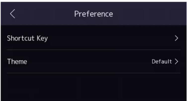
Figure 7-18 Preference Settings
Shortcut Key
Choose the shortcut key that displayed on the authentication page, including the QR code function, the call function, call type, and the password entering function.
i Note
You can select call type from Call Room, Call Center, Call Specified Room No. and Call APP.
Call Room
When you tap the call button on the authentication page, you should dial a room No. to call.
Call Center
When you tap the call button on the authentication page, you can call the center directly.
Call Specified Room No.
You should set a room No. When you tap the call button on the authentication page, you can call the configured room directly without dialing.
Call APP
When you tap the call button on the authentication page, you will call the mobile client where the device is added.
Password
Enable this function and you can enter the password to authenticate via password.
QR Code
You can use the QR code scanning function on the authentication interface. The device will upload the information associated with the obtained QR code to the platform.
Theme
You can set the theme of the prompt window on the authentication page. You can select Theme as /Advertisement/Authentication.
Authentication
After selecting this mode, the live view of the authentication page will be disabled, and in the meanwhile, the person's name, employee ID, face pictures will all be hidden.
Advertisement
After selecting this mode, the advertising area and identification authentication area of the device will be displayed on separate screens. Video and advertising information playback, welcome speech display are supported.
7.11 System Maintenance
You can view the system information and the capacity. You can also upgrade the device, restore to factory settings, restore to default settings, reboot the device, set face parameters and view version information.
Long tap on the initial page for 3 s and slide to the left/right by following the gesture and login the home page. Tap Maint.
Hold the ? on the upper-right corner of the page and enter the password to view the version of the device.
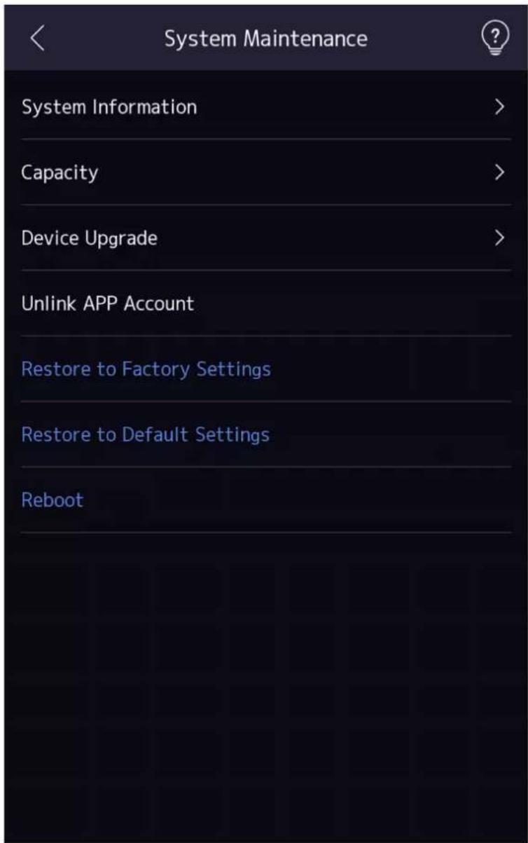
System Information
You can view the device model, serial No., versions, address, production data, QR code, and open source code license.

Note
The page may vary according to different device models. Refers to the actual page for details.
Capacity
You can view the number of, user, face picture, card, and event.
Device Upgrade
Online Update
If the device has been connected to Hik-Connect and network, when there is a new installation package in Hik-Connect, you can tap Device Upgrade → Online Update to upgrade the device system.
Update via USB
Plug the USB flash drive in the device USB interface. Tap Device Upgrade → Update via USB, and the device will read the digicap.dav file in the USB flash drive to start upgrading.
Unlink APP Account
After unlinking APP account, you cannot operate via APP.
Restore to Default Settings
All parameters, except for the communication settings, remotely imported user information, will be restored to the default settings. The system will reboot to take effect.
Restore to Factory Settings
All parameters will be restored to the factory settings. The system will reboot to take effect.
Reboot
Reboot the device.
Advanced Settings
Long Tap ? on the right corner to enter the advanced settings page. Enter the password.
Face Parameter
Custom Anti-Spoofing Detection
Face Liveness Level
After enabling face anti-spoofing function, you can set the matching security level when performing live face authentication.
Anti-Spoofing Detection Threshold
The larger the value, the smaller the false accept rate and the larger the false rejection rate. The smaller the value, the larger the false accept rate and the smaller the false rejection rate.
Lock Face for Anti-Spoofing Protection
After enabling this function, the device will lock automatically when anti-spoofing detection failed.
Lock Duration
The lock duration after enabling Lock Face for Anti-Spoofing Protection when anti-spoofing detection failed.
Version Information
You can view the device information.
7.12 Video Intercom
After adding the device to the client software, you can call the device from the client software, call the main station from the device, call the client software from the device, or call the indoor station from the device.
7.12.1 Call Client Software from Device
Steps
- Get the client software from the supplied disk or the official website, and install the software according to the prompts.
- Run the client software and the control panel of the software pops up.
- Click Device Management to enter the Device Management interface.
- Add the device to the client software.

For details about adding device, see Add Device.
- Call the client software.
1) Tap on the device initial page.
2) Enter 0 in the pop-up window.
3) Tap to call the client software.
- Tap Answer on the pop-up page of the client software and you can start two-way audio between the device and the client software.

If the device is added to multiple client softwares and when the device is calling the client software, only the first client software added the device will pop up the call receiving window.
7.12.2 Call Center from Device
Steps
- Get the client software from the supplied disk or the official website, and install the software according to the prompts.
- Run the client software and the control panel of the software pops up.
- Click Device Management to enter the Device Management interface.
- Add the main station and the device to the client software.

For details about adding device, see Add Device.
- Set the main station's IP address and SIP address in the remote configuration page.

Note
For details about the operation, see the user manual of the main station.
-
Call the center.
-
If you have configured to call center in the Basic Settings, you can tap 📋 to call the center.
-
If you have not configured to call center in the Basic Settings, you should tap → to call the center
-
Answers the call via the main station and starts two-way audio.

Note
The device will call the main station in priority.
7.12.3 Call Device from Client Software
Steps
-
Get the client software from the supplied disk or the official website, and install the software according to the prompts.
-
Run the client software and the control panel of the software pops up.
-
Click Device Management to enter the Device Management page.
-
Add the device to the client software.

Note
For details about adding device, see Add Device.
- Enter the Live View page and double-click the added device to start live view.

Note
For details about operations in the Live View page, see Live View in the user manual of the client software.
-
Right click the live view image to open the right-click menu.
-
Click Start Two-Way Audio to start two-way audio between the device and the client software.
7.12.4 Call Room from Device
Steps
-
Get the client software from the supplied disk or the official website, and install the software according to the prompts.
-
Run the client software and the control panel of the software pops up.
-
Click Device Management to enter the Device Management interface.
-
Add the indoor station and the device to the client software.

Note
For details about adding device, see Add Device.
-
Link a user to an indoor station and set a room No. for the indoor station.
-
Call the room.
-
If you have configured a specified room No. in the Basic Settings, you can tap ☑ to call the room.
-
If you have not configured a specified room No. in the Basic Settings, you should tap ☑ on the authentication page of the device. Enter the room No. on the dial page and tap ☑ to call the room.
-
After the indoor station answers the call, you can start two-way audio with the indoor station.
7.12.5 Call Mobile Client from Device
Steps
- Get the mobile mobile client from the supplied disk or the official website, and install the software according to the prompts.
- Run the mobile client and add the device to the mobile client.

Note
For details, see the user manual of the mobile client.
- Enter Basic Settings → Shortcut Key and enable Call APP.
- Go back to the initial page and call the mobile client.
1) Tap on the device initial page.
2) Tap to call the mobile client.
7.12.6 Call Room from Device
Steps
- Get the client software from the supplied disk or the official website, and install the software according to the prompts.
- Run the client software and the control panel of the software pops up.
- Tap 📞 on the device initial page.
- Enter the room No., and tap call button.
Chapter 8 Quick Operation via Web Browser
8.1 Select Language
You can select a language for the device system.
Click 📄 in the top right of the web page to enter the Device Language Settings page. You can select a language for the device system from the drop-down list.
By default, the system language is English.

Note
After you change the system language, the device will reboot automatically.
Click Next to complete the settings.
8.2 Time Settings
Click 📄 in the top right of the web page to enter the wizard page. After setting device language, you can click Next to enter the Time Settings page.
Time Zone
Select the device located time zone from the drop-down list.
Time Sync.
NTP
You should set the NTP server's IP address, port No., and interval.
Manual
By default, the device time should be synchronized manually. You can set the device time manually or check Sync. with Computer Time to synchronize the device time with the computer's time.
Server Address/NTP Port/Interval
You can set the server address, NTP port, and interval.
Click Next to save the settings and go to the next parameter. Or click Skip to skip time settings.
8.3 Privacy Settings
Set the picture uploading and storage parameters.
Click 📄 in the top right of the web page to enter the wizard page. After previous settings, you can click Next to enter the Privacy Settings page.
Picture Uploading and Storage
Save Picture When Authenticating
Save picture when authenticating automatically.
Upload Picture When Authenticating
Upload the pictures when authenticating to the platform automatically.
Save Registered Picture
The registered face picture will be saved to the system if you enable the function.
Upload Picture After Linked Capture
Upload the pictures captured by linked camera to the platform automatically.
Save Pictures After Linked Capture
If you enable this function, you can save the picture captured by linked camera to the device.
Click Next to complete the settings.
8.4 Administrator Settings
Steps
- Click 📋 in the top right of the web page to enter the wizard page. After setting device language, time, environment and privacy, you can click Next to enter the Administrator Settings page.
- Enter the employee ID and name of the administrator.
- Select a credential to add.

Note
You should select at least one credential.
1) Click Add Face to upload a face picture from local storage.

Note
The uploaded picture should be within 200 K, in JPG、JPEG、PNG format.
2) Click Add Card to enter the Card No. and select the property of the card.

Note
Up to 5 cards can be supported.
3) Click Add Fingerprint to add fingerprints.

Note
Up to 10 fingerprints are allowed.
Click Complete to complete the settings.
8.5 No.and System Network
Steps
-
Click ☑ in the top right of the web page to enter the wizard page. After previous settings, you can click Next to enter the No. and System Network settings page.
-
Set the device type.
If set the device type as Door Station or Access Control Device, you can set the floor No., door station No., and click More to set Community No., Building No., and Unit No.
If set the device type as Outer Door Station, you can set outer door station No., and community No.
- Click Complete to save the settings after the configuration.
Device Type
The device can be used as a door station or outer door station. Select a device type from the drop-down list.
Floor No.
Set the device installed floor No.
Door Station No.
Set the device installed floor No.

The main door station No. is 0, and the sub door station No. ranges from 1 to 16.
Community No.
Set the device community No.
Building No.
Set the device building No.
Unit No.
Set the device unit No.
Chapter 9 Operation via Web Browser
9.1 Login
You can login via the web browser.

Make sure the device is activated. For detailed information about activation, see Activation.
Login via Web Browser
Enter the device IP address in the address bar of the web browser and press Enter to enter the login page.
Enter the device user name and the password. Click Login.
9.2 Forgot Password
If you forget the device password, you can change the device password via security questions.
Steps

You can change the device password via PC web.
- ClickForgot Password on the login page.
- Select the verification method.
- Answer the reserved security questions.

The answers are configured when you first activate the device.
- Create a new password and confirm the password.
- Click Next to save the settings.
9.3 Overview
You can view the live video of the device, person information, network status, basic information, and device capacity.
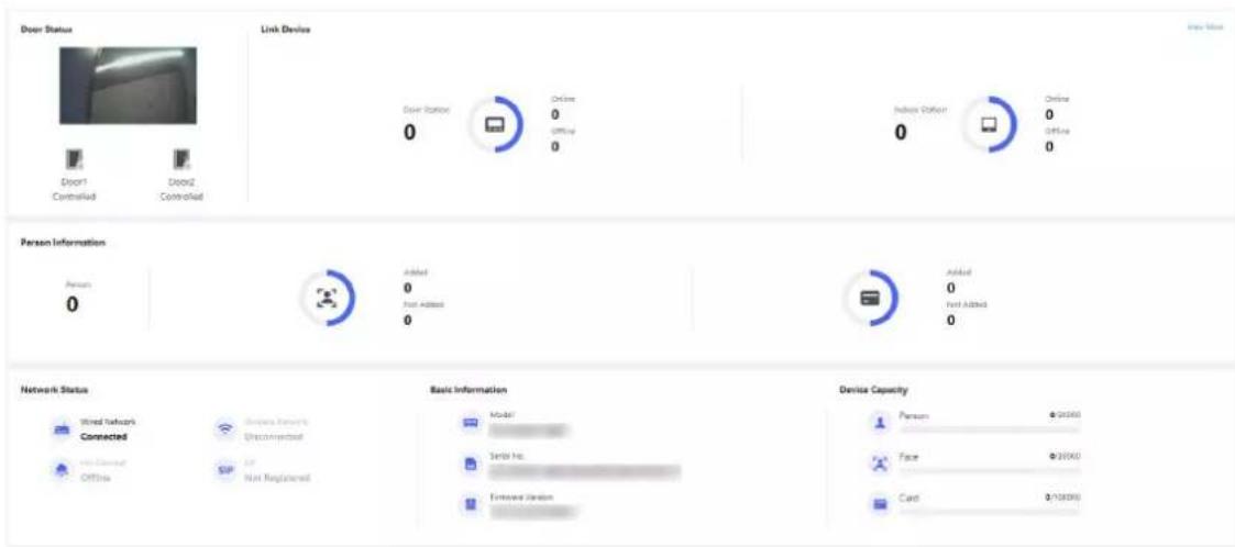
Figure 9-1 Overview Page
Function Descriptions:
Real-Time Event
You can view the event Employee ID, Name, Card No., Event Type, Time, and Operation. You can also click View More to enter the page of Event Search. You can select event types, enter the employee ID, the name, the card No., the start time, and the end time, and click Search. The results will be displayed on the right panel.
Door Status
Click to view the device live view.

Set the volume when starting live view.

If you adjust the volume when starting two-way audio, you may hear a repeated sounds.

You can capture image when starting live view.

Select the streaming type when starting live view. You can select from the main stream, substream or third stream.

Full screen view.

You can record when starting live view.

The door status is open/closed/remaining open/remaining closed.
Controlled Status
You can control the door to be opened, closed, remaining open or remaining closed according to your actual needs.
Person Information
You can view the added and not added information of person face, card and fingerprint.
Network Status
You can view the connected and registered status of wired network, wireless network, cloud service and ISUP.
Basic Information
You can view the model, serial No. and firmware version.
Device Capacity
You can view the person, face, card, fingerprint and event capacity.
9.4 Person Management
Click Add to add the person's information, including the basic information, certificate, authentication and settings.
Basic Information
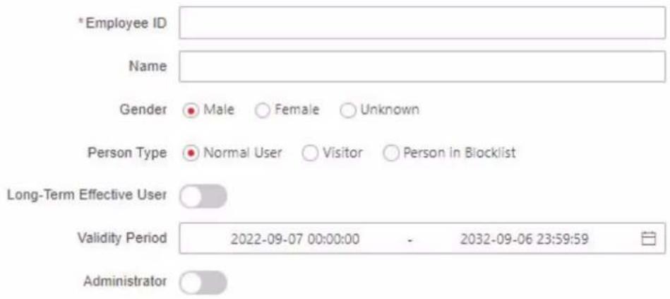
Certificate Configuration
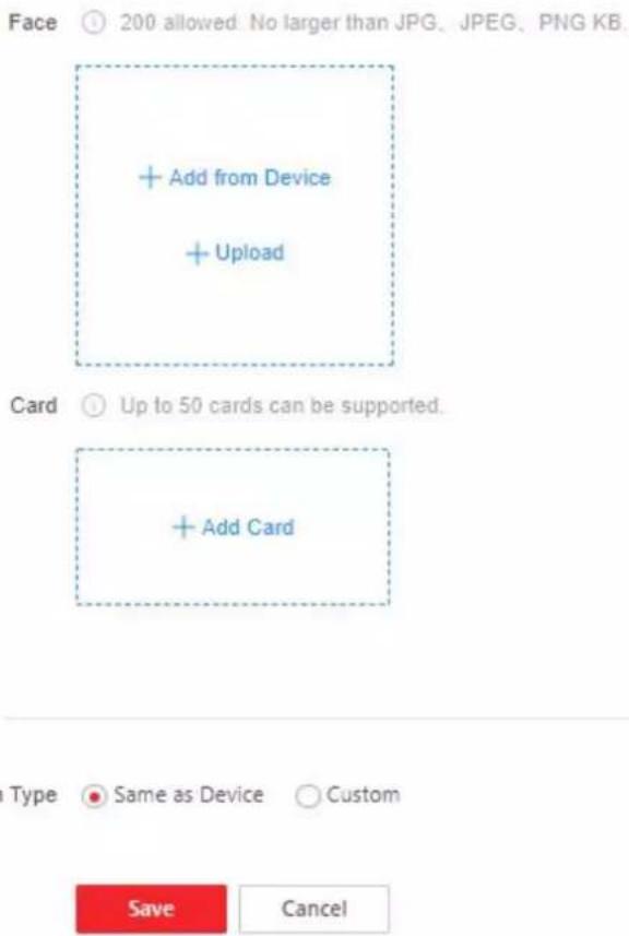
Figure 9-2 Add Person
Add Basic Information
Click Person Management → Add to enter the Add Person page.
Add the person's basic information, including the employee ID, the person's name, the gender, person type.
If you select Visitor as the person type, you can set the visit times.
Click Save to save the settings.
Set Permission Time
Click Person Management → Add to enter the Add Person page.
Enable Long-Term Effective User, or set Validity Period and the person can only have the permission within the configured time period according to your actual needs.
Click Save to save the settings.
Add Face Picture
Click Person Management → Add to enter the Add Person page.
Click + on the right to upload a face picture from the local PC.

Note
The picture format should be JPG or JPEG or PNG, and the size should be less than 200 K.
Click Save to save the settings.
Add Card
Click Person Management → Add to enter the Add Person page.
Click Add Card, enter the Card No. and select the Property, and click OK to add the card.

Note
Up to 50 cards can be added.
Click Save to save the settings.
Add Fingerprint

Note
Only devices supporting the fingerprint function can add the fingerprint.
Click Person Management → Add to enter the Add Person page.
Click Add Fingerprint, and press your finger on the fingerprint module of the device to add your fingerprint.
Click Save to save the settings.
Set Room No.
Click Person Management → Add to enter the Add Person page.
Enter the Floor No. and Room No..
Click to delete it.
Click Save to save the settings.
Authentication Settings
Click Person Management → Add to enter the Add Person page.
Set Authentication Type as Same as Device or Custom.
Click Save to save the settings.
9.5 Search Event
Click Event Search to enter the Search page.
Enter the search conditions, including the event type, the employee ID, the name, the card No., the start time, and the end time, and click Search.
The results will be displayed on the right panel.
9.6 Configuration
9.6.1 View Device Information
View the device name, language, model, serial No., version, IO input, IO output, Lock, Local RS-485, alarm input, alarm output, and device capacity, etc.
Click Configuration → System → System Settings → Basic Information to enter the configuration page.
You can view device name, language, model, serial No., version, IO input, IO output, Lock, Local RS-485, alarm input, alarm output, and device capacity, etc.
9.6.2 Set Time
Set the device's time, time zone, synchronization mode, server address, NTP port, and interval.
Click Configuration → System → System Settings → Time Settings.
Click Save to save the settings after the configuration.
Time Zone
Select the device located time zone from the drop-down list.
Time Sync.
NTP
You should set the NTP server's IP address, port No., and interval.
Manual
By default, the device time should be synchronized manually. You can set the device time manually or check Sync. with Computer Time to synchronize the device time with the computer's time.
Server Address Type/Server Address/NTP Port/Interval
You can set the server address type, server address, NTP port, and interval.
9.6.3 Change Administrator's Password
Steps
- Click Configuration → System → User Management.
- Click ↗
- Enter the old password and create a new password.
- Confirm the new password.
- Click Save.

Caution
The password strength of the device can be automatically checked. We highly recommend you change the password of your own choosing (using a minimum of 8 characters, including at least three kinds of following categories: upper case letters, lower case letters, numbers, and special characters) in order to increase the security of your product. And we recommend you change your password regularly, especially in the high security system, changing the password monthly or weekly can better protect your product.
Proper configuration of all passwords and other security settings is the responsibility of the installer and/or end-user.
9.6.4 View Device Arming/Disarming Information
View device arming type and arming IP address.
Click Configuration → System → User Management → Arming/Disarming Information.
You can view the device arming/disarming information. Click Refresh to refresh the page.
9.6.5 Network Settings
Set TCP/IP, port, Wi-Fi parameters, ISUP, and platform access.

Note
Some device models do not support Wi-Fi or mobile data settings. Refer to the actual products when configuration.
Set Basic Network Parameters
Click Configuration → Network → Network Settings → TCP/IP.

Figure 9-3 TCP/IP Settings Page
Set the parameters and click Save to save the settings.
NIC Type
Select a NIC type from the drop-down list. By default, it is Self-Adaptive.
DHCP
If uncheck the function, you should set the IPv4 address, IPv4 subnet mask and IPv4 default gateway.
If you check the function, the system will allocate the IPv4 address, IPv4 subnet mask, the IPv4 default gateway automatically.
DNS Server
Set the preferred DNS server and the Alternate DNS server according to your actual need.
Set Wi-Fi Parameters
Set the Wi-Fi parameters for device wireless connection.
Steps
i Note
The function should be supported by the device.
- Click Configuration → Network → Network Settings → Wi-Fi.
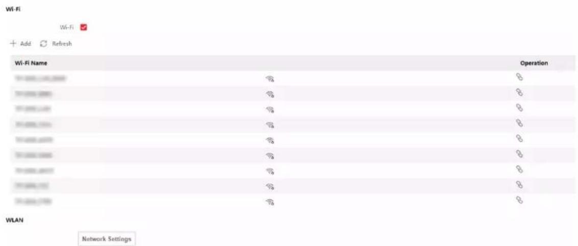
Figure 9-4 Wi-Fi Settings Page
- Check Wi-Fi.
-
Select a Wi-Fi
-
Click Connect of a Wi-Fi in the list and enter the Wi-Fi password.
-
Click Manual Add and enter a Wi-Fi's SSID, working mode, security mode, and password. Click OK.
-
Set the WLAN parameters.
1) Set the IP address, subnet mask, and default gateway. Or enable DHCP and the system will allocate the IP address, subnet mask, and default gateway automatically.
-
Set the DNS server. Set the preferred DNS server and alternate DNS server. Or enable DHCP and the system will allocate the preferred DNS server and alternate DNS server automatically.
-
Click Save.
Set Port Parameters
Set the HTTP, HTTPS, HTTP Listening, RTSP and Server port parameters.
Click Configuration → Network → Network Service → HTTP(S) .
HTTP
It refers to the port through which the browser accesses the device. For example, when the HTTP Port is modified to 81, you need to enter http://192.0.0.65:81 in the browser for login.
HTTPS
Set the HTTPS for accessing the browser. Certificate is required when accessing.
HTTP Listening
The device can send alarm information to the event alarm IP address or domain name via HTTP protocol/HTTPS protocol. Edit the event alarm IP address or domain name, URL, port, and protocol.

Note
The event alarm IP address or domain name should support the HTTP protocol/HTTPS protocol to receive the alarm information.
Click Configuration → Network → Network Service → RTSP.
RTSP
It refers to the port of real-time streaming protocol.
Click Configuration → Network → Device Access → SDK Server.
SDK Server
It refers to the port through which the client adds the device.
Platform Access
Platform access provides you an option to manage the devices via platform.
Steps
- Click Configuration → Network → Device Access → Hik-Connect to enter the settings page.

Note
Hik-Connect is an application for mobile devices. With the App, you can view live image of the device, receive alarm notification and so on.
-
Check Enable to enable the function.
-
Optional: Check the checkbox of Custom, and you can set the server address by yourself.
-
Enter the server IP address, and verification code.

Note
6 to 12 letters (a to z, A to Z) or numbers (0 to 9), case sensitive. You are recommended to use a combination of no less than 8 letters or numbers.
- Enable Video Encryption, and create the password and confirm it.

Note
After adding the device to APP, you need to enter the video encryption password to live view the device.
- Optional: Click View to view the device QR code. Scan the QR code to account.

Note
Scan the QR code before it loses efficacy.
- Optional: Click More to set the network connection priority.
1) Enable WLAN or Wired Network according to your actual needs.
1) Hold and drag to adjust the access priority.
- Click Save to enable the settings.
Set ISUP Parameters
Set the ISUP parameters for accessing device via ISUP protocol.
Steps

Note
The function should be supported by the device.
- Click Configuration → Network → Device Access → ISUP.
- Check Enable.
- Set the ISUP version, server address, port, device ID, and the ISUP status.

Note
If you select 5.0 as the version, you should set the encryption key as well.
- Set the ISUP listening parameters, including ISUP alarm center IP address/domain name, ISUP alarm center URL, and ISUP alarm center port.
- Click Save.
9.6.6 Set Video and Audio Parameters
Set the image quality and resolution.
Set Video Parameters
Click Configuration → Video/Audio → Video.
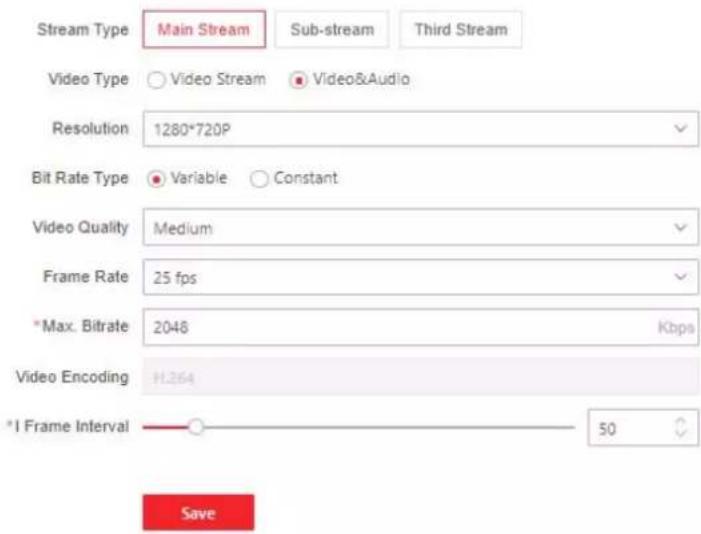
Figure 9-5 Video Settings Page
Set the stream type, the video type, the resolution, the bitrate type, the Max. bitrate, and I Frame Interval.
Click Save to save the settings after the configuration.
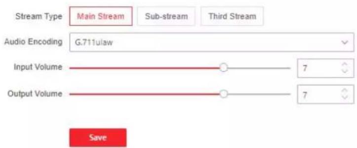
Figure 9-6 Audio Settings
Set the stream type, input volume, output volume and enable voice prompt according to your actual needs.
Click Save to save the settings.
9.6.7 Set Image Parameters
You can adjust the image parameters, video parameters, supplement light parameters, beauty parameters, enable WDR and set capture interval.
Steps
- Click Configuration → Image .
- Configure the parameters to adjust the image.
Image Adjustment
Drag the block or enter the value to adjust the live video's brightness, contrast, saturation, and sharpness.
Video Adjustment (Video Standard)
Set the video frame rate when performing live view remotely. After changing the standard, you should reboot the device to take effect.
PAL
25 frames per second. Suitable for mainland China, Hong Kong (China), the Middle East countries, Europe countries, etc.
NTSC
30 frames per second. Suitable for the USA, Canada, Japan, Taiwan (China), Korea, the Philippines, etc.
Supplement Light
Set the supplement light type, mode, start time and end time. You can also set the brightness.
Beauty
Set whiten and smooth value for the face appeared on the device live view page.
Backlight
Enable or disable WDR.
When there are both very bright and very dark areas simultaneously in the view, WDR balances the brightness level of the whole image and provide clear images with details.
Start All Recording
You can click Ⓞ to record when starting live view.
Capture Interval
You can click to capture image when starting live view.
Full Screen
You can click for full screen view.
- Click Restore Default Settings to restore the parameters to the default settings.
9.6.8 Alarm Settings
Set the alarm output parameters.
Steps
-
Click Configuration → Event → Alarm Settings → Alarm Output.
-
Set Alarm Name and Output Delay.
9.6.9 Access Control Settings
Set Authentication Parameters
Click Configuration → Access Control → Authentication Settings.

Note
The functions vary according to different models. Refers to the actual device for details.
Click Save to save the settings after the configuration.
If select Terminal 1:
Terminal/Terminal Type/Terminal Model
Select terminal and get the terminal description. They are read-only.
Enable Authentication Device
Enable the authentication function.
Authentication
Select an authentication mode according to your actual needs from the drop-down list.
Recognition Interval
You can set the interval between 2 continuous recognition of a same person during the authentication. In the configured interval, Person A can only recognized once. If another person (Person B) has recognized during the interval, Person A can recognized again.
Authentication Interval
You can set the authentication interval of the same person when authenticating. The same person can only authenticate once in the configured interval. A second authentication will be failed.
Alarm of Max. Failed Attempts
Enable to report alarm when the card reading attempts reach the set value.
Tampering Detection
Enable the anti-tamper detection for the card reader.
Card No. Reversing
The read card No. will be in reverse sequence after enabling the function.
If select Terminal 2:
Terminal/Terminal Type/Terminal Model
Select terminal and get the terminal description. They are read-only.
Enable Authentication Device
Enable the authentication function.
Sub Card Reader Position
You can select sub card reader position as different or same side as the main card reader.
Authentication
Select an authentication mode according to your actual needs from the drop-down list.
Recognition Interval
You can set the interval between 2 continuous recognition of a same person during the authentication. In the configured interval, Person A can only recognized once. If another person (Person B) has recognized during the interval, Person A can recognized again.
Alarm of Max. Failed Attempts
Enable to report alarm when the card reading attempts reach the set value.
Communication with Controller Every
When the access control device cannot connect with the card reader for longer than the set time, the card reader will turn offline automatically.
Max. Interval When Entering Password
When you entering the password on the card reader, if the interval between pressing two digits is longer than the set value, the digits you pressed before will be cleared automatically.
OK LED Polarity/Error LED Polarity
Set OK LED Polarity/Error LED Polarity of the access control device according to the card reader parameters. Generally, adopts the default settings.
Tampering Detection
Enable the anti-tamper detection for the card reader.
Set Door Parameters
Click Configuration → Access Control → Door Parameters.
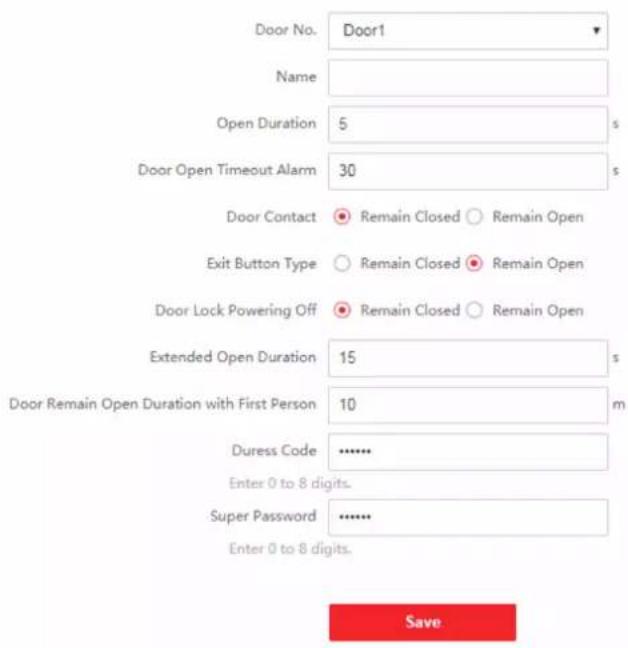
Figure 9-7 Door Parameters Settings Page
Click Save to save the settings after the configuration.
Door Name
You can create a name for the door.
Open Duration
Set the door unlocking duration. If the door is not opened for the set time, the door will be locked.
Door Open Timeout Alarm
An alarm will be triggered if the door has not been closed within the configured time duration.
Door Magnetic Sensor Type
You can set the door contact as Remain Open or Remain Closed according to your actual needs. By default, it is Remain Closed.
Exit Button Type
You can set the exit button as Remain Open or Remain Closed according to your actual needs. By default, it is Remain Open.
Door Lock Powering Off Status
You can set the door lock status when the door lock is powering off. By default, it is Remain Closed.
Extended Open Duration
The door contact can be enabled with appropriate delay after person with extended access needs swipes her/his card.
Door Remain Open Duration with First Person
Set the door open duration when first person is in. After the first person is authorized, it allows multiple persons access the door or other authentication actions.
Duress Code
The door can open by inputting the duress code when there is duress. At the same time, the client can report the duress event.
Super Password
The specific person can open the door by inputting the super password.

Note
The duress code and the super code should be different.
Set RS-485 Parameters
You can set the RS-485 parameters including the peripheral, address, baud rate, etc.
Click Configuration → Access Control → RS-485 Settings.
Check Enable RS-485, and set the parameters.
Click Save to save the settings after the configuration.
No.
Set the RS-485 No.
Peripheral Type
Select a peripheral from the drop-down list according the actual situation. You can select from Card Reader, Extension Module, Access Controller, or Disable.

Note
After the peripheral is changed and saved, the device will reboot automatically.
RS-485 Address
Set the RS-485 Address according to your actual needs.

Note
If you select Access Controller: If connect the device to a terminal via the RS-485 interface, set the RS-485 address as 2. If you connect the device to a controller, set the RS-485 address according to the door No.
Baud Rate
The baud rate when the devices are communicating via the RS-485 protocol.
Set Wiegand Parameters
You can set the Wiegand transmission direction.
Steps

Note
Some device models do not support this function. Refer to the actual products when configuration.
- Click Configuration → Access Control → Wiegand Settings.
- Check Wiegand to enable the Wiegand function.
- Set a transmission direction.
Input
The device can connect a Wiegand card reader.
Output
The can connect an external access controller. And the two devices will transmit the card No. via Wiegand 26 or 34.
- Click Save to save the settings.

Note
If you change the peripheral, and after you save the device parameters, the device will reboot automatically.
Set Terminal Parameters
You can set terminal parameters for accessing.
Click Configuration → Access Control → Terminal Parameters.
You can set Working Mode as Access Control Mode. The access control mode is the device normal mode. You should authenticate your credential for accessing.
Click Save to save the settings after the configuration.
9.6.10 Set Video Intercom Parameters
The device can be used as a door station, outer door station, or access control device. You should set the device No. before usage.
Click Configuration → Intercom → Device No. .
If set the device type as Door Station or Access Control Device, you can set the floor No., door station No., and click More to set Community No., Building No., and Unit No.
Click Save to save the settings after the configuration.
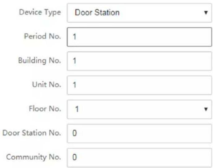

Figure 9-8 Device No. Settings
Device Type
The device can be used as a door station or outer door station. Select a device type from the drop-down list.

Note
If you change the device type, you should reboot the device.
Floor No.
Set the device installed floor No.
Door Station No.
Set the device installed floor No.

Note
• If you change the No., you should reboot the device.
- The main door station No. is 0, and the sub door station No. ranges from 1 to 16.
Community No.
Set the device community No.
Building No.
Set the device building No.
Unit No.
Set the device unit No.

Note
If you change the No., you should reboot the device.
If set the device type as Outer Door Station, you can set outer door station No., and community No.
Outer Door Station No.
If you select outer door station as the device type, you should enter a number between 1 and 99.

Note
If you change the No., you should reboot the device.
Community No.
Set the device community No.
Set Linked Network Settings
Click Configuration → Intercom → Linked Network Settings.
You can set the device type, the SIP server's IP address, and the main station's IP address.
After setting the parameters, you can communicate among the access control device, door station, indoor station, main station, and the platform.
Click Save to save the settings after the configuration.
9.6.11 Press Button to Call
Steps
- Click Configuration → Intercom → Press Button to Call.
-
Set the parameters.
-
Edit call No. for every button.
- Check Call Management Center to set the button calling center.

Note
If you check Call Management Center and set the call No. as well, call management center has higher privilege than call No.
9.6.12 Card Settings
Set Card Security
Click Configuration → Card Settings → Card Type to enter the settings page.
Set the parameters and click Save.
Enable NFC Card
Enable the function and you can present the NFC card to authenticate. In order to prevent the mobile phone from getting the data of the access control, you can disable NFC card to increase the security level of the data.

Disable NFC card cannot completely avoid presenting NFC card.
Enable M1 Card
Enable M1 card and authenticating by presenting M1 card is available.
M1 Card Encryption
Sector
M1 card encryption can improve the security level of authentication.
Enable the function and set the encryption sector. By default, Sector 13 is encrypted. It is recommended to encrypt sector 13.
Enable CPU Card
Enable CPU card and authenticating by presenting CPU card is available.
Set Card No. Authentication Parameters
Set the card reading content when authenticate via card on the device.
Go to Configuration → Card Settings → Card No. Authentication Settings.
Select a card authentication mode and click Save.
Full Card No.
All card No. will be read.
Wiegand 26 (3 bytes)
The device will read card via Wiegand 26 protocol (read 3 bytes).
Wiegand 34 (4 bytes)
The device will read card via Wiegand 34 protocol (read 4 bytes).
9.6.13 Time and Attendance Settings
If you want to track and monitor when the persons start/stop work and monitor their working hours and late arrivals, early departures, time taken on breaks, and absenteeism, you can add the person to the shift group and assign a shift schedule (a rule for the attendance defining how the schedule repeats, the shift type, break settings, and the card swiping rule.) to the shift group to define the attendance parameters for the persons in the shift group.
Set Manual Attendance via Web
Set the attendance mode as manual, and you should select a status manually when you take attendance.
Before You Start
Add at least one user, and set the user's authentication mode. For details, see User Management.
Steps
- Click Configuration → Attendance to enter the settings page.
- Set the Attendance Mode as Manual.
- Enable the Attendance Status Required and set the attendance status lasts duration.
- Enable a group of attendance status.

The Attendance Property will not be changed.
- Optional: Select an status and change its name if required.
Result
You should select an attendance status manually after authentication.

If you do not select a status, the authentication will be failed and it will not be marked as a valid attendance.
Set Auto Attendance via Web
Set the attendance mode as auto, and you can set the attendance status and its available schedule. The system will automatically change the attendance status according to the configured schedule.
Before You Start
Add at least one user, and set the user's authentication mode. For details, see User Management.
Steps
-
Click Configuration → Attendance to enter the settings page.
-
Set the Attendance Mode as Auto.
- Enable the Attendance Status function.
- Enable a group of attendance status.

The Attendance Property will not be changed.
- Optional: Select an status and change its name if required.
- Set the status' schedule. Refers to for details.
Set Manual and Auto Attendance via Web
Set the attendance mode as Manual and Auto, and the system will automatically change the attendance status according to the configured schedule. At the same time you can manually change the attendance status after the authentication.
Before You Start
Add at least one user, and set the user's authentication mode. For details, see User Management.
Steps
- Click Configuration → Attendance to enter the settings page.
- Set the Attendance Mode as Manual and Auto.
- Enable the Attendance Status function.
- Enable a group of attendance status.

The Attendance Property will not be changed.
- Optional: Select an status and change its name if required.
- Set the status' schedule. Refers to for details.
Result
On the initial page and authenticate. The authentication will be marked as the configured attendance status according to the schedule. If you tap the edit icon on the result tab, you can select a status to take attendance manually, the authentication will be marked as the edited attendance status.
Example
If set the Break Out as Monday 11:00, and Break In as Monday 12:00, the valid user's authentication from Monday 11:00 to 12:00 will be marked as break.
9.6.14 Set Privacy Parameters
Set the event storage type, picture upload and storage parameters, and the picture clearing parameters.
Go to Configuration → Security → Privacy Settings
Event Storage Settings
Select a method to delete the event. You can select from Delete Old Events Periodically, Delete Old Events by Specified Time, or Overwriting.
Delete Old Events Periodically
Drag the block or enter number to set the period for event deleting. All events will be deleted according to the configured time duration.
Delete Old Events by Specified Time
Set a time and all events will be deleted on the configured time.
Overwriting
The earliest 5% events will be deleted when the system detects the stored events has been over 95% of the full space.
Authentication Settings
Display Authentication Result
You can check Face Picture, Name, and Employee ID, to display the authentication result.
Name De-identification
You can check Name De-identification, and the whole name will not be displayed.
Picture Uploading and Storage
Save Picture When Authenticating
Save picture when authenticating automatically.
Upload Picture When Authenticating
Upload the pictures when authenticating to the platform automatically.
Save Registered Picture
The registered face picture will be saved to the system if you enable the function.
Upload Picture After Linked Capture
Upload the pictures captured by linked camera to the platform automatically.
Save Pictures After Linked Capture
If you enable this function, you can save the picture captured by linked camera to the device.
Clear All Pictures in Device

All pictures cannot be restored once they are deleted.
Clear Registered Face Pictures
All registered pictures in the device will be deleted.
Clear Captured Pictures
All captured pictures in the device will be deleted.
9.6.15 Set Biometric Parameters
Set Basic Parameters
Click Configuration → Smart → Smart.

Note
The functions vary according to different models. Refers to the actual device for details.
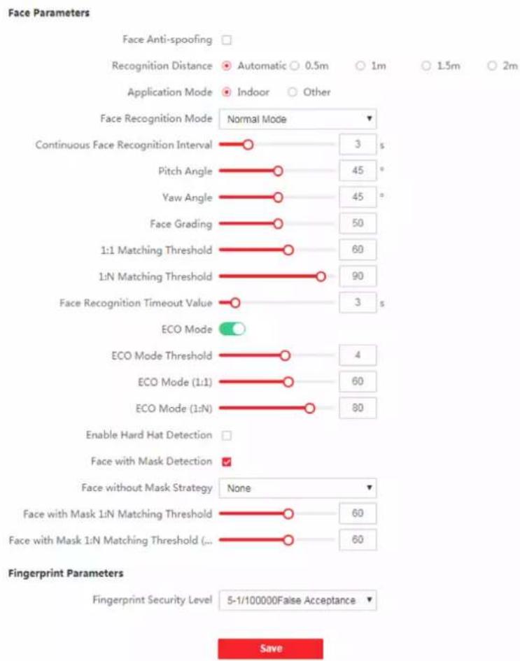
bar
| Category | Value | | ---------------------------- | ----- | | Continuous Face Recognition Interval | 3 | | Pitch Angle | 45 | | Yaw Angle | 45 | | Face Grading | 50 | | 1:1 Matching Threshold | 60 | | 1:N Matching Threshold | 90 | | Face Recognition Timeout Value | 3 | | ECO Mode | ✓ | | ECO Mode Threshold | 4 | | ECO Mode (1:1) | 60 | | ECO Mode (1:N) | 80 | | Enable Hard Hat Detection | ✓ | | Face with Mask Detection | ✓ | | Face without Mask Strategy | None | | Face with Mask 1:N Matching Threshold | 60 | | Face with Mask 1:N Matching Threshold (...') | 60 |Figure 9-9 Smart Settings Page
Click Save to save the settings after the configuration.
Face Anti-spoofing
Enable or disable the live face detection function. If enabling the function, the device can recognize whether the person is a live one or not.
i Note
- Biometric recognition products are not 100% applicable to anti-spoofing environments. If you require a higher security level, use multiple authentication modes.
• After disabling face anti-spoofing function, there will be spoofing recognition risks.
Anti-Spoofing Detection Level
After enabling the face anti-spoofing function, you can set the matching security level when performing live face authentication.
Recognition Distance
Select the distance between the authenticating user and the device camera.
Pitch Angle
The maximum pitch angle when starting face authentication.
Yaw Angle
The maximum yaw angle when starting face authentication.
Face Picture Quality Grade for Applying
Set the face picture quality grade according to your needs.
1:1 Matching Threshold
Set the matching threshold when authenticating via 1:1 matching mode. The larger the value, the smaller the false accept rate and the larger the false rejection rate.
i Note
You are recommended to retain the default value. The adjustment will affect the face misidentification rate and rejection rate.
1:N Matching Threshold
Set the matching threshold when authenticating via 1:N matching mode. The larger the value, the smaller the false accept rate and the larger the false rejection rate.
i Note
You are recommended to retain the default value. The adjustment will affect the face misidentification rate and rejection rate.
Face Recognition Timeout Value
Set the timeout value when face recognizing. If the face recognition time is longer than the configured value, the system will pop up a prompt.
ECO Mode
After enabling the ECO mode, the device will use the IR camera to authenticate faces in the low light or dark environment. And you can set the ECO mode threshold, ECO mode (1:N), and ECO mode (1:1).

After enabling ECO mode, the face will be recognized in weak light or no light environment. After disabling ECO mode, face recognition effect will decline in weak light or no light environment.
ECO Mode Threshold
The larger the value, the device enter the ECO Mode easier.
ECO Mode (1:1)
Set the matching threshold when authenticating via ECO mode 1:1 matching mode. The larger the value, the smaller the false accept rate and the larger the false rejection rate.
ECO Mode (1:N)
Set the matching threshold when authenticating via ECO mode 1:N matching mode. The larger the value, the smaller the false accept rate and the larger the false rejection rate
Face with Mask Detection
After enabling the face with mask detection, the system will recognize the captured face with mask picture or not. You can set face with mask1:N matching threshold, it's ECO mode, and the strategy.

After enabling Face with Mask Detection function, recognition effect of people without mask will be influenced.
None
The function is disabled. The device will not detect whether a person is wearing a face mask or not.
Reminder of Wearing Face Mask
If the person do not wear the face mask when authenticating, the device will pop up a prompt and the door will open.
Must Wear Face Mask
If the person do not wear the face mask when authenticating, the device will pop up a prompt and the door will keep closed.
Face with Mask & Face (1:1)
Set the matching value when authenticating with face mask via 1:1 matching mode. The larger the value, the smaller the false accept rate and the larger the false rejection rate.
Face with Mask 1:N Matching Threshold
Set the matching threshold when authenticating with face mask via 1:N matching mode. The larger the value, the smaller the false accept rate and the larger the false rejection rate.
Face with Mask & Face (1:1 ECO)
Set the matching value when authenticating with face mask via ECO mode 1:1 matching mode. The larger the value, the smaller the false accept rate and the larger the false rejection rate.
Face with Mask 1:N Matching Threshold (ECO Mode)
Set the matching threshold when authenticating with face mask via ECO mode 1:N matching mode. The larger the value, the smaller the false accept rate and the larger the false rejection rate.
Enable Hard Hat Detection
After enabling the hard hat detection, you can set the strategy.
None
The function is disabled. The device will not detect whether a person is wearing a hard hat or not.
Reminder of Wearing
If the person do not wear the hard hat when authenticating, the device will pop up a prompt and the door will open.
Must Wear
If the person do not wear the hard hat when authenticating, the device will pop up a prompt and the door will keep closed.
Set Recognition Area
Click Configuration → Smart → Area Configuration.
Drag the yellow frame in the live video or enter values for the left, right, top, and bottom margin to adjust the recognition area. Only the face within the area can be recognized by the system.
Click Save to save the settings.
9.6.16 Preference Settings
Set the theme, notice publication, prompt schedule, custom prompt, and authentication result text.
Set Preference
You can set the display theme and the sleep time for the device.
Set Theme
Click Configuration → Preference.
Sleep
Enable Sleep and the device will enter the sleep mode when no operation within the configured sleep time.
Display Mode
You can select display theme for device authentication. You can select Display Mode as Authentication, Simple or Advertisement. When you select Simple, the information of name, ID, face picture will be not displayed.
Notice Publication
You can set the notice publication for the device.
Click Configuration → Preference → Notice Publication.
Theme Management
Click Media Library Management → + to upload the picture from the local PC.
You can click +, and set Name and Type to create a theme. After creating the theme, click + in the Theme Management panel to select pictures in the media library. Click OK to add pictures to the theme.
Customize Audio Content
Customize the output audio content when authentication succeeded and failed.
Steps
- Click Configuration → Video/Audio → Prompt.
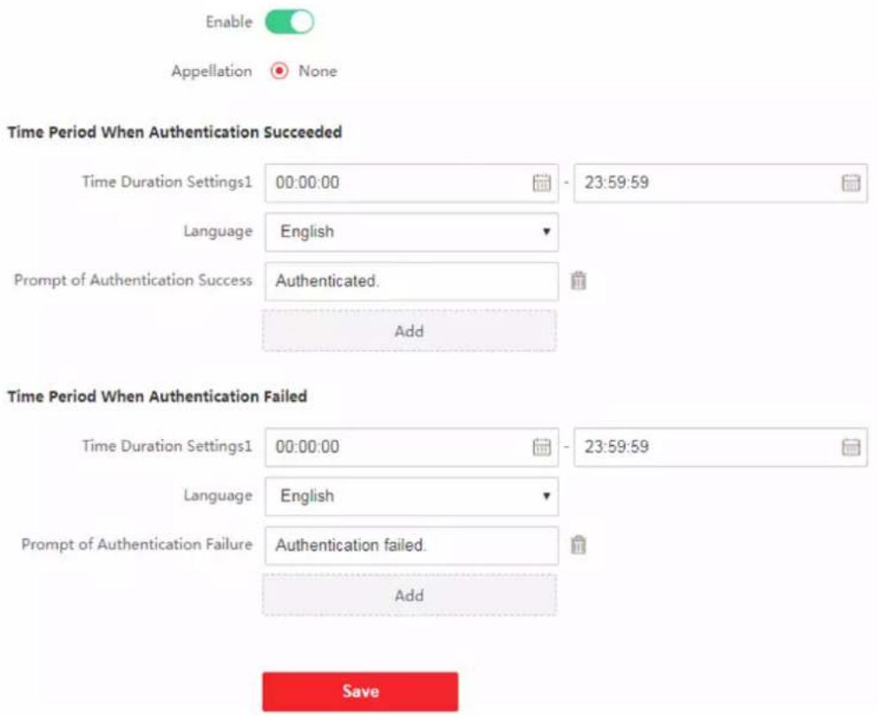
Figure 9-10 Customize Audio Content
- Set the appellation.
- Enable the function.
- Set the time duration when authentication succeeded.
1) Click Add.
2) Set the time duration and the language.

If authentication is succeeded in the configured time duration, the device will broadcast the configured content.
3) Enter the audio content.
4) Optional: Repeat substep 1 to 3.
5) Optional: Click 🔒 to delete the configured time duration.
- Set the time duration when authentication failed.
1) Click Add.
2) Set the time duration and the language.

If authentication is failed in the configured time duration, the device will broadcast the configured content.
3) Enter the audio content.
4) Optional: Repeat substep 1 to 3.
5) Optional: Click 🔒 to delete the configured time duration.
- Optional: Import custom prompt.
1) Select Custom Type.
2) Select the importing path, and click Import.
- Click Save to save the settings.
Customize Prompt Voice
You can customize prompt voices for the device.
Steps
- Click Configuration → Preference → Custom Prompt.
- Click ☐ → ☐ and import audio file from local PC according to your actual needs.

The uploaded audio file should be less than 512 kb, in WAV format.
Configure Authentication Result Text
Steps
- Go to Configuration → Preference → Authentication Result Text.
- Enable Customize Authentication Result Text.
- Enter custom texts.
- Click Save.
9.6.17 Upgrade and Maintenance
Reboot device, restore device parameters, and upgrade device version.
Reboot Device
Click Maintenance and Security → Maintenance → Restart.
Click Restart to reboot the device.
Upgrade
Click Maintenance and Security → Maintenance → Upgrade.
Select an upgrade type from the drop-down list. Click and select the upgrade file from your local PC. Click Upgrade to start upgrading.
If the device has been connected to Hik-Connect and network, when there is a new installation package in Hik-Connect, you can click Upgrade after Online Update to upgrade the device system.

Note
Do not power off during the upgrading.
Restore Parameters
Click Maintenance and Security → Maintenance → Backup and Reset.
Restore All
All parameters will be restored to the factory settings. You should activate the device before usage.
Restore
The device will restore to the default settings, except for the device IP address and the user information.
Import and Export Parameters
Click Maintenance and Security → Maintenance → Backup and Reset.
Export
Click Export to export the device parameters.

Note
You can import the exported device parameters to another device.
Import
Click ☐ and select the file to import. Click Import to start import configuration file.
Click Advanced Settings, and enter the admin password.
Face Parameter
Custom Anti-Spoofing Detection
Face Liveness Level
After enabling face anti-spoofing function, you can set the matching security level when performing live face authentication.
Anti-Spoofing Detection Threshold
The larger the value, the smaller the false accept rate and the larger the false rejection rate. The smaller the value, the larger the false accept rate and the smaller the false rejection rate.
Lock Face for Anti-Spoofing Protection
After enabling this function, the device will lock automatically when anti-spoofing detection failed.
Lock Duration
The lock duration after enabling Lock Face for Anti-Spoofing Protection when anti-spoofing detection failed.
Unlock
You can click Unlock according to your needs.
Version Information
You can view the device information.
9.6.18 Device Debugging
You can set device debugging parameters.
Steps
- Click Maintenance and Security → Maintenance → Device Debugging.
- You can set the following parameters.
Enable SSH
To raise network security, disable SSH service. The configuration is only used to debug the device for the professionals.
Print Log
You can click Export to export log.
Capture Network Packet
You can set the Capture Packet Duration, Capture Packet Size, and click Start Capture to capture.
9.6.19 Log Query
You can search and view the device logs.
Go to Maintenance and Security → Maintenance → Log.
Set the major and minor type of the log type. Set the start time and end time for searching, and click Search.
The results will be displayed below, which including the No., time, the major type the minor type, the channel No., the local/remote user information, the remote host IP, etc.
9.6.20 Security Mode Settings
Set the security mode for logging in the client software.
On the Device for Management page, click Maintenance and Security → Security → Security Service.
Select a security mode, and click Save.
Security Mode
High security level for user information verification when logging in the client software.
Compatible Mode
The user information verification is compatible with the old client software version when logging in.
Illegal Login Lock
After enabling Illegal Login Lock, the device will be locked if it is logged in illegally.
9.6.21 Certificate Management
It helps to manage the server/client certificates and CA certificate.
i Note
The function is only supported by certain device models.
Create and Install Self-signed Certificate
Steps
- Go to Configuration → System → Security → Certificate Management.
- In the Certificate Files area, select a Certificate Type from the drop-down list.
- Click Create.
- Input certificate information.
- Click OK to save and install the certificate.
The created certificate is displayed in the Certificate Details area.
The certificate will be saved automatically.
- Download the certificate and save it to an asking file in the local computer.
- Send the asking file to a certification authority for signature.
- Import the signed certificate.
1) Select a certificate type in the Import Passwords area, and select a certificate from the local, and click Install.
2) Select a certificate type in the Import Communication Certificate area, and select a certificate from the local, and click Install.
Install Other Authorized Certificate
If you already has an authorized certificate (not created by the device), you can import it to the device directly.
Steps
-
Go to Configuration → System → Security → Certificate Management.
-
In the Import Passwords and Import Communication Certificate areas, select certificate type and upload certificate.
- Click Install.
Install CA Certificate
Before You Start
Prepare a CA certificate in advance.
Steps
- Go to Configuration → System → Security → Certificate Management.
- Create an ID in the Import CA Certificate area.

Note
The input certificate ID cannot be the same as the existing ones.
- Upload a certificate file from the local.
- Click Install.
Chapter 10 Other Platforms to Configure
You can also configure the device via iVMS-4200 Client Software or HikCentral Access Control. For details, see the platforms' user manual.
iVMS-4200 Client Software
Click/tap the link to view the client software's user manual.
http://enpinfodata.hikvision.com/analysisQR/showQR/ca930247
HikCentral Access Control (HCAC)
Click/tap the link to view the HCAC's user manual.
http://enpinfodata.hikvision.com/analysisQR/showQR/f2f6cf42
Appendix A. Tips for Scanning Fingerprint
Recommended Finger
Forefinger, middle finger or the third finger.
Correct Scanning
The figure displayed below is the correct way to scan your finger:
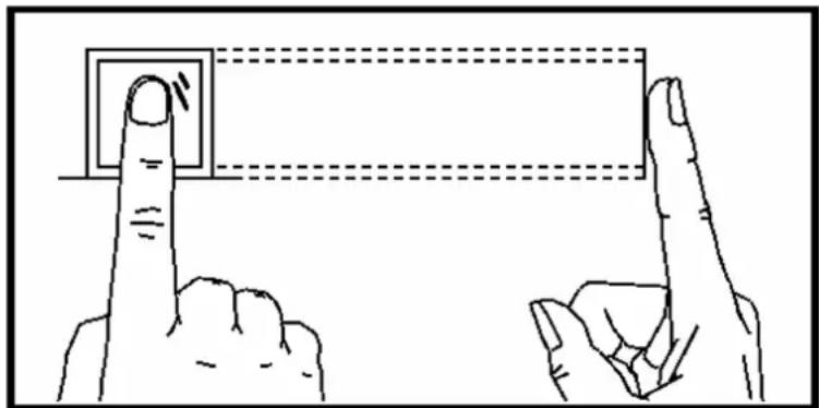
natural_image
Illustration of two hands pointing at a square with dashed lines indicating alignment or measurement (no text or symbols)You should press your finger on the scanner horizontally. The center of your scanned finger should align with the scanner center.
Incorrect Scanning
The figures of scanning fingerprint displayed below are incorrect:
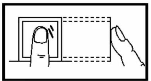
natural_image
Illustration of a finger pressing a square button with a dashed rectangular outline (no text or symbols)Vertical
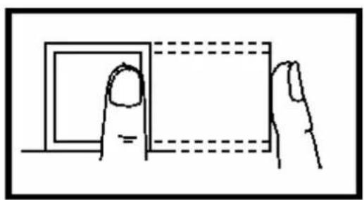
natural_image
Line drawing of a hand holding a square with dashed border (no text or symbols)Edge I
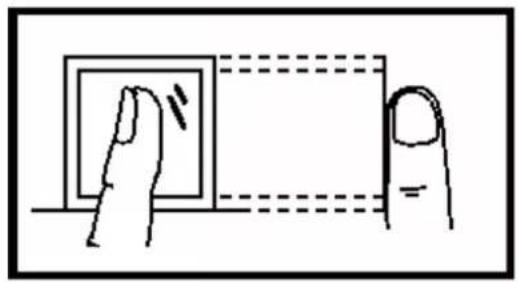
natural_image
Simple line drawing of a finger pressing a button on a square (no text or symbols)Side
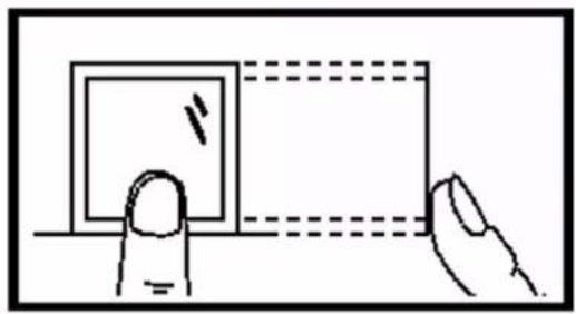
natural_image
Simple line drawing of a hand holding a square object with dashed lines indicating alignment or measurement (no text or symbols)Edge II
Environment
The scanner should avoid direct sun light, high temperature, humid conditions and rain.
When it is dry, the scanner may not recognize your fingerprint successfully. You can blow your finger and scan again.
Others
If your fingerprint is shallow, or it is hard to scan your fingerprint, we recommend you to use other authentication methods.
If you have injuries on the scanned finger, the scanner may not recognize. You can change another finger and try again.
Appendix B. Tips When Collecting/Comparing Face Picture
The position when collecting or comparing face picture is as below:
Positions (Recommended Distance: 0.5 m)
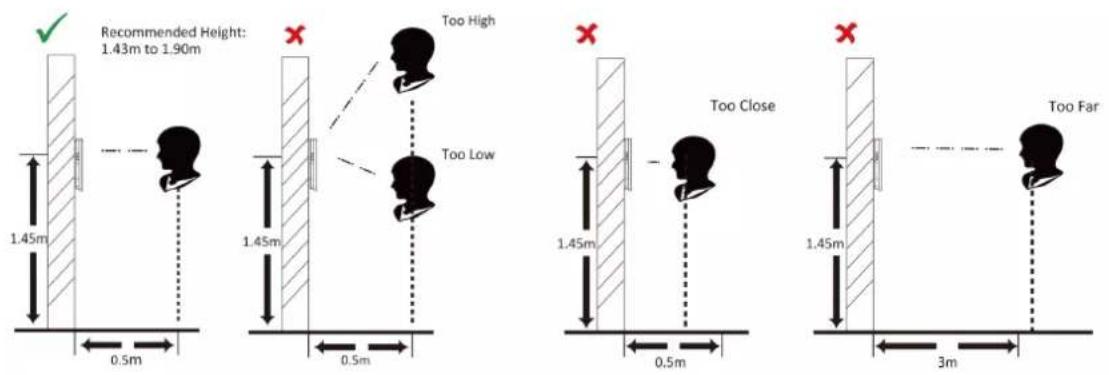
Expression
- Keep your expression naturally when collecting or comparing face pictures, just like the expression in the picture below.

- Do not wear hat, sunglasses, or other accessories that can affect the facial recognition function.
- Do not make your hair cover your eyes, ears, etc. and heavy makeup is not allowed.
Posture
In order to get a good quality and accurate face picture, position your face looking at the camera when collecting or comparing face pictures.

Size
Make sure your face is in the middle of the collecting window.

Appendix C. Tips for Installation Environment
1. Light Source Illumination Reference Value

Candle: 10Lux

Bulb: 100\~850Lux

Sunlight: More than 1200Lux
- Install the device at least 2 meters away from the light, and at least 3 meters away from the window or door.
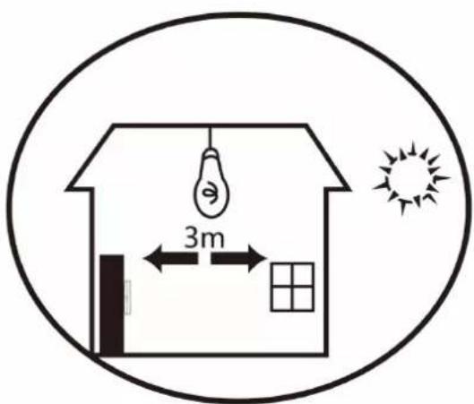
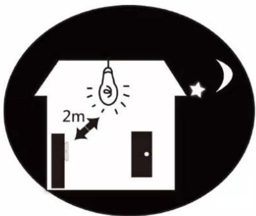
- Avoid backlight, direct and indirect sunlight

Backlight

Direct Sunlight
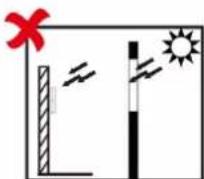
Direct Sunlight through Window
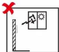
Indirect Light
through Window
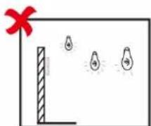
Close to Light
Appendix D. Dimension
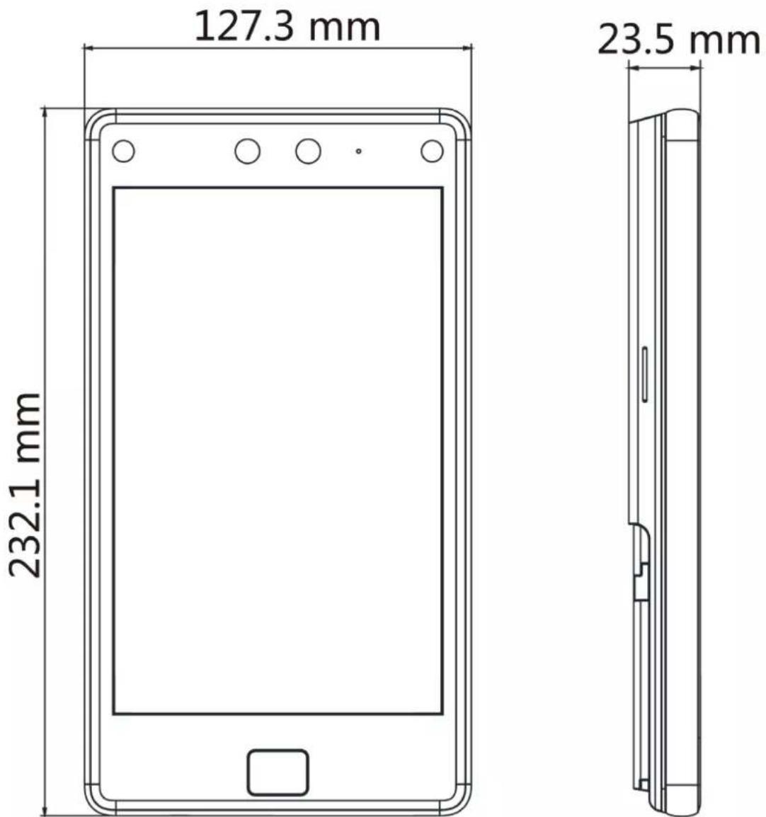
Figure D-1 Dimension
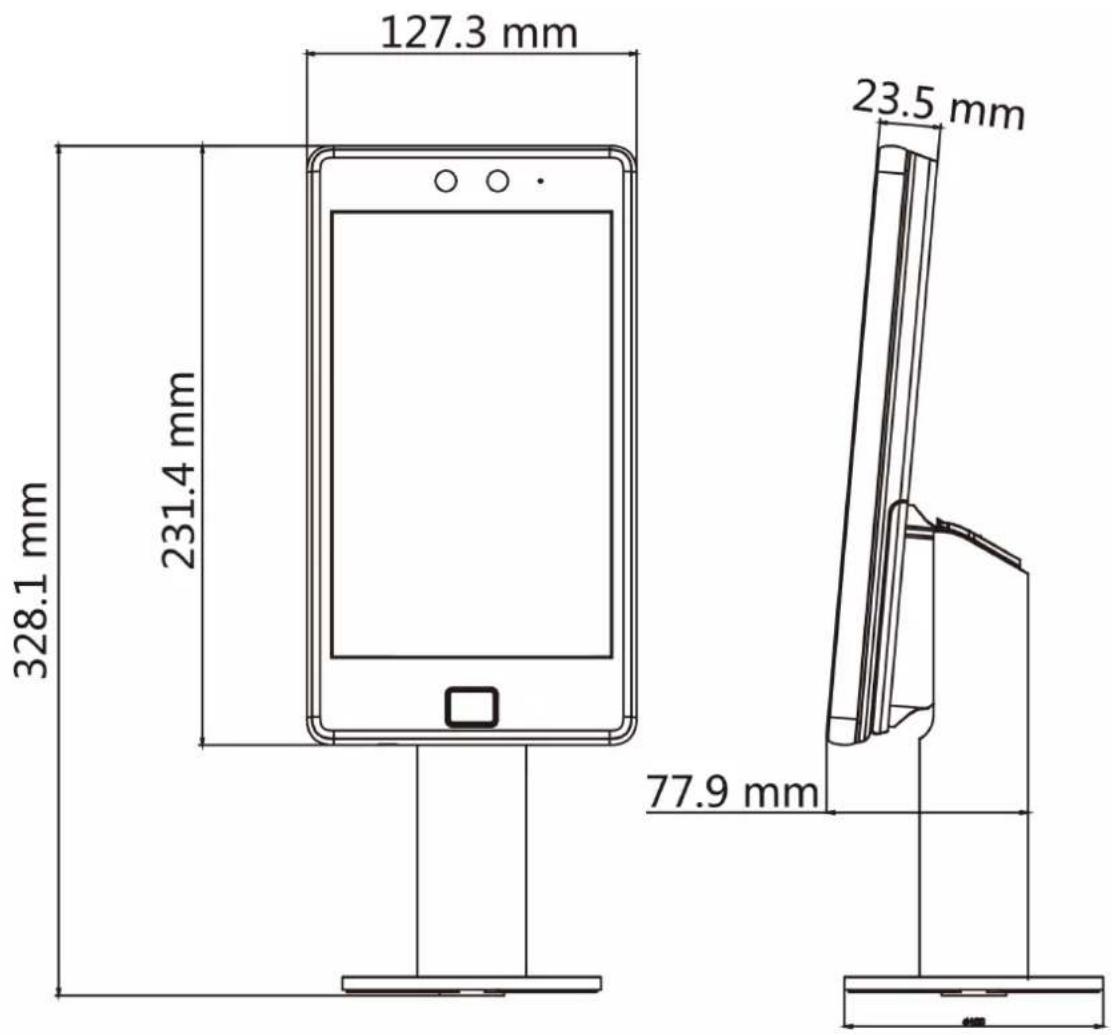
Figure D-2 Dimension with Bracket
Appendix E. Function Differences
| Model DS-K1T680DFG | DS-K1T680DF | DS-K1T680DFW | DS-K1T680DF-E1 | DS-K1T680DG | DS-K1T680DW | DS-K1T680D | DS-K1T680D-E1 |
| Wi-Fi NotSupport | NotSupport | Support NotSupport | NotSupport | NotSupport | Support NotSupport | NotSupport | NotSupport |
| PoE NotSupport | NotSupport | NotSupport | Support NotSupport | NotSupport | NotSupport | NotSupport | Support |
| 3G/4G Support NotSupport | Support NotSupport | Support NotSupport | Support NotSupport | Support NotSupport | Support NotSupport | Support NotSupport | Support NotSupport |

See Far, Go Further
- About this Product
- Acknowledgment of Intellectual Property Rights
- LEGAL DISCLAIMER
- Data Protection
- Symbol Conventions
- Regulatory Information
- FCC Information
- EU Conformity Statement
- Safety Instruction
- Danger:
- ⚠️ Cautions:
- Contents
- Chapter 1 Overview ...... 1
- Chapter 2 Appearance ...... 2
- Chapter 3 Installation .... 4
- Chapter 4 Wiring 8
- Chapter 5 Activation ...... 17
- Chapter 6 Quick Operation 22
- Chapter 7 Basic Operation ...... 32
- Login 32
- Communication Settings 38
- User Management 45
- Data Management 54
- Identity Authentication .... 55
- Basic Settings 57
- Chapter 8 Quick Operation via Web Browser 75
- Chapter 9 Operation via Web Browser .... 78
- Configuration 83
- Chapter 10 Other Platforms to Configure .... 113
- Appendix A. Tips for Scanning Fingerprint 114
- Appendix B. Tips When Collecting/Comparing Face Picture 116
- Appendix C. Tips for Installation Environment 118
- Appendix D. Dimension 119
- Appendix E. Function Differences ...... 121
- Chapter 1 Overview
- Overview
- Features
- Chapter 2 Appearance
- Chapter 3 Installation
- Installation Environment
- Surface Mounting
- Steps
- Chapter 4 Wiring
- Note
- Terminal Description
- Wire Normal Device
- Wire Secure Door Control Unit
- Wire Fire Module
- Wiring Diagram of Door Open When Powering Off
- Type 1
- Type 2
- Wiring Diagram of Door Locked When Powering Off
- Chapter 5 Activation
- Activate via Device
- Caution
- Activate via Web Browser
- Activate via SADP
- Before You Start
- Activate Device via Client Software
- Chapter 6 Quick Operation
- Select Language
- Set Password Change Type
- Change Password via Email Address
- Change via Security Questions
- Set Network Parameters
- Tap Next.
- Wired Network
- Wi-Fi
- Access to Platform
- Privacy Settings
- Set Administrator
- Chapter 7 Basic Operation
- Login
- Login by Administrator
- Login by Activation Password
- Forgot Password
- Tap Forgot Password.
- Communication Settings
- Set Wired Network Parameters
- Set Wi-Fi Parameters
- Set RS-485 Parameters
- Set Wiegand Parameters
- Set ISUP Parameters
- Port No.
- Device ID
- ISUP Key
- Platform Access
- User Management
- Add Administrator
- i Note
- Enable Administrator Permission
- Add Face Picture
- Look at the camera.
- Administrator
- Normal User
- Add Fingerprint
- Add Card
- View Password
- Set Authentication Mode
- Device
- Custom
- Search and Edit User
- Search User
- Edit User
- Data Management
- Delete Data
- Import Data
- Export Data
- Identity Authentication
- 1:N Matching
- 1: 1 Matching
- Authenticate via Single Credential
- Face
- Fingerprint
- Card
- QR Code
- Password
- Authenticate via Multiple Credential
- Basic Settings
- Voice Settings
- Time Settings
- Sleeping (s)
- Select Language
- Community No.
- Building No.
- Unit No.
- Beauty
- Set Biometric Parameters
- Set Access Control Parameters
- Time and Attendance Status Settings
- Disable Attendance Mode via Device
- Set Manual Attendance via Device
- Result
- Set Auto Attendance via Device
- Example
- Set Manual and Auto Attendance via Device
- Preference Settings
- Shortcut Key
- Call Room
- Call Center
- Call Specified Room No.
- Call APP
- Theme
- Authentication
- Advertisement
- System Maintenance
- System Information
- Capacity
- Device Upgrade
- Online Update
- Update via USB
- Unlink APP Account
- Restore to Default Settings
- Restore to Factory Settings
- Reboot
- Advanced Settings
- Face Parameter
- Custom Anti-Spoofing Detection
- Face Liveness Level
- Anti-Spoofing Detection Threshold
- Lock Face for Anti-Spoofing Protection
- Lock Duration
- Version Information
- Video Intercom
- Call Client Software from Device
- Call Center from Device
- Call Device from Client Software
- Call Room from Device
- Call Mobile Client from Device
- Call Room from Device
- Chapter 8 Quick Operation via Web Browser
- Select Language
- Time Settings
- Time Zone
- Time Sync.
- NTP
- Manual
- Server Address/NTP Port/Interval
- Privacy Settings
- Picture Uploading and Storage
- Save Picture When Authenticating
- Upload Picture When Authenticating
- Save Registered Picture
- Upload Picture After Linked Capture
- Save Pictures After Linked Capture
- Administrator Settings
- No.and System Network
- Device Type
- Floor No.
- Door Station No.
- Chapter 9 Operation via Web Browser
- Login
- Login via Web Browser
- Forgot Password
- Overview
- Real-Time Event
- Door Status
- Controlled Status
- Person Information
- Network Status
- Basic Information
- Device Capacity
- Person Management
- Add Basic Information
- Set Permission Time
- Add Face Picture
- Add Card
- Add Fingerprint
- Set Room No.
- Authentication Settings
- Search Event
- Configuration
- View Device Information
- Set Time
- Server Address Type/Server Address/NTP Port/Interval
- Change Administrator's Password
- View Device Arming/Disarming Information
- Network Settings
- Set Basic Network Parameters
- NIC Type
- DHCP
- DNS Server
- Set Wi-Fi Parameters
- Set Port Parameters
- HTTP
- HTTPS
- HTTP Listening
- RTSP
- SDK Server
- Platform Access
- Set ISUP Parameters
- Set Video and Audio Parameters
- Set Video Parameters
- Set Image Parameters
- Image Adjustment
- Video Adjustment (Video Standard)
- PAL
- NTSC
- Supplement Light
- Backlight
- Start All Recording
- Capture Interval
- Full Screen
- Alarm Settings
- Access Control Settings
- Set Authentication Parameters
- Terminal/Terminal Type/Terminal Model
- Enable Authentication Device
- Recognition Interval
- Authentication Interval
- Alarm of Max. Failed Attempts
- Tampering Detection
- Card No. Reversing
- Sub Card Reader Position
- Communication with Controller Every
- Max. Interval When Entering Password
- OK LED Polarity/Error LED Polarity
- Set Door Parameters
- Door Name
- Open Duration
- Door Open Timeout Alarm
- Door Magnetic Sensor Type
- Exit Button Type
- Door Lock Powering Off Status
- Extended Open Duration
- Door Remain Open Duration with First Person
- Duress Code
- Super Password
- Set RS-485 Parameters
- No.
- Peripheral Type
- RS-485 Address
- Baud Rate
- Set Wiegand Parameters
- Input
- Output
- Set Terminal Parameters
- Set Video Intercom Parameters
- Outer Door Station No.
- Set Linked Network Settings
- Press Button to Call
- Card Settings
- Set Card Security
- Enable NFC Card
- Enable M1 Card
- M1 Card Encryption
- Sector
- Enable CPU Card
- Set Card No. Authentication Parameters
- Full Card No.
- Wiegand 26 (3 bytes)
- Wiegand 34 (4 bytes)
- Time and Attendance Settings
- Set Manual Attendance via Web
- Set Auto Attendance via Web
- Set Manual and Auto Attendance via Web
- Set Privacy Parameters
- Event Storage Settings
- Delete Old Events Periodically
- Delete Old Events by Specified Time
- Overwriting
- Display Authentication Result
- Name De-identification
- Clear All Pictures in Device
- Clear Captured Pictures
- Set Biometric Parameters
- Set Basic Parameters
- Face Anti-spoofing
- Anti-Spoofing Detection Level
- Recognition Distance
- Pitch Angle
- Yaw Angle
- Face Picture Quality Grade for Applying
- 1:1 Matching Threshold
- 1:N Matching Threshold
- Face Recognition Timeout Value
- ECO Mode
- ECO Mode Threshold
- ECO Mode (1:1)
- ECO Mode (1:N)
- Face with Mask Detection
- None
- Reminder of Wearing Face Mask
- Must Wear Face Mask
- Face with Mask & Face (1:1)
- Face with Mask 1:N Matching Threshold
- Face with Mask & Face (1:1 ECO)
- Face with Mask 1:N Matching Threshold (ECO Mode)
- Enable Hard Hat Detection
- Reminder of Wearing
- Must Wear
- Set Recognition Area
- Preference Settings
- Set Preference
- Set Theme
- Sleep
- Display Mode
- Notice Publication
- Theme Management
- Customize Audio Content
- Customize Prompt Voice
- Configure Authentication Result Text
- Upgrade and Maintenance
- Reboot Device
- Upgrade
- Restore Parameters
- Restore All
- Restore
- Import and Export Parameters
- Export
- Import
- Unlock
- Device Debugging
- Enable SSH
- Print Log
- Capture Network Packet
- Log Query
- Security Mode Settings
- Security Mode
- Compatible Mode
- Illegal Login Lock
- Certificate Management
- Create and Install Self-signed Certificate
- Install Other Authorized Certificate
- Install CA Certificate
- Chapter 10 Other Platforms to Configure
- Appendix A. Tips for Scanning Fingerprint
- Recommended Finger
- Correct Scanning
- Incorrect Scanning
- Environment
- Others
- Appendix B. Tips When Collecting/Comparing Face Picture
- Expression
- Posture
- Size
- Appendix C. Tips for Installation Environment
- Light Source Illumination Reference Value
- Appendix D. Dimension
Brand : Hikvision
Model : DS-K1T680DFW
Category : Access Control