
KD-IP922DEC-II - Audio/video converter Key Digital - Free user manual and instructions
Find the device manual for free KD-IP922DEC-II Key Digital in PDF.

| Product Type | Audio/Video Decoder (HD over IP) |
| Model | KD-IP922DEC-II |
| Brand | Key Digital |
| Dimensions (W x D x H) | 4.5 x 4.5 x 1.5 in (115 x 115 x 38 mm) |
| Weight | 0.5 lb (0.23 kg) |
| Power Supply | 5V DC, 2A (external adapter) |
| Power Consumption | 10W max |
| Video Input | Ethernet (IP stream) |
| Video Output | HDMI 1.4 |
| Max Resolution | 1080p @ 60Hz |
| Audio Support | PCM, Dolby Digital, DTS (pass-through) |
| Network Interface | 10/100 Ethernet, RJ-45 |
| Control | IR extender, RS-232, TCP/IP |
| Mounting | Surface mount or rack shelf (optional) |
| Operating Temperature | 32°F to 104°F (0°C to 40°C) |
| Compliance | FCC, CE, RoHS |
| Maintenance | Keep vents clean; wipe with dry cloth |
| Safety | Use only provided power adapter; avoid moisture |
| Spare Parts / Repairability | Limited; contact Key Digital support |
Frequently Asked Questions - KD-IP922DEC-II Key Digital
User questions about KD-IP922DEC-II Key Digital
0 question about this device. Answer the ones you know or ask your own.
Ask a new question about this device
Download the instructions for your Audio/video converter in PDF format for free! Find your manual KD-IP922DEC-II - Key Digital and take your electronic device back in hand. On this page are published all the documents necessary for the use of your device. KD-IP922DEC-II by Key Digital.
USER MANUAL KD-IP922DEC-II Key Digital
Verified Network Switch Guide
For use with Key Digital AV over IP Systems
IMPORTANT: Configure your network switch according to this guide BEFORE connecting your AV over IP units.
Introduction Pg. 2
Key Digital Supported AV over IP Models Pg. 2
System Facts Pg. 3
Network Switch Requirements for KD AV over IP Pg. 4
Verified Network Switches Table Pg. 5
Araknis Verified Switch Model List
Araknis Setup for 1080p Systems Pg. 9
Araknis Setup for 4K Systems Pg. 12
Cisco Verified Switch Model List
Cisco Meraki Series Pg. 16
Cisco SG / SF Series Pg. 17
Cisco Catalyst Setup for 4K Systems Pg. 24
D-Link Verified Switch Model List
D-Link Setup for 4K and 1080p Systems Pg. 35
Edgecore Verified Switch Model List
Edgecore AS4610-54T / Cumulus Linux version 3.7.15 Pg. 42
Engenius Verified Switch Model List
Engenius IGMP Setup for 1080p Systems Pg. 43
Linksys Verified Switch Model List
Linksys IGMP Setup for LGS***MPC models
Pg. 47
Linksys IGMP Setup for 1080p Systems (Legacy) Pg. 51
Linksys IGMP Setup for 4K Systems (Legacy) Pg. 57
Luxul Verified Switch Model List
Luxul IGMP Setup for 4K and 1080p Systems Pg. 65
Netgear Verified Switch Model List
Netgear AV Series Network Switches Pg. 71
Netgear IGMP Setup for 4K and 1080p Systems Pg. 74
Niveo Verified Switch Model List
Niveo NGS Series IGMP Setup for 4K systems Pg. 79
Pakedge Verified Switch Model List
Pakedge S3 IGMP Setup for 4K and 1080p Systems Pg. 83
Pakedge SX Series IGMP Setup for 4K and 1080p Systems Pg. 89
Signamax Verified Switch Model List
Signamax SC-300 Series IGMP Setup for 4K systems Pg. 94
Titan Networkx Verified Switch Model List
Titan Networkx IGMP Setup for 1080p Systems Pg. 99
TP Link Verified Switch Model List
TP Link for 4K Systems
Pg. 10
Wifi Router Setup and Requirements Pg. 116
Introduction
Thank you for purchasing a Key Digital AV over IP system.
Follow the instructions in this guide to enable the features for a reliable foundation for your AVoIP system.
Your AV over IP system MUST be integrated with one these verified network switches to function.
Network Switch setup may be different for 4K (KD-IP922, KD-IP822, KD-IP1022) and 1080p (KD-IP1080, KD-IP120) systems. There are separate setup instructions for each where applicable.
Key Digital AV over IP Supported Models:
- 4K Systems:
- KD-IP922ENC, KD-IP922DEC
○ KD-IP822ENC, KD-IP822DEC - KD-IP1022ENC, KD-IP1022DEC
• 1080p Systems:
○ KD-IP1080Tx, KD-IP1080Rx
- KD-IP120Tx, KD-IP120Rx, KD-IP120POETx, KD-IP120POERx
Key Digital's AV over IP product family consists of many different models. Not all models are compatible together. See Key Digital AV over IP Selection Guide for more info
| Key Digital® AV over IP Solutions Selection Guide | ||||||||
| Key Digital's AV over IP Solutions create expandable AV over IP systems that can be scaled to fit any size installation or project. | ||||||||
| KD-IP1022ENC | KD-IP1022DEC | KD-IP922ENC | KD-IP922DEC | KD-IP822ENC | KD-IP822DEC | KD-IP1080Tx | KD-IP1080Rx | |
| Encoder Tx / Decoders Rx | Encoder (ENO) | Decoder (DEC) | Encoder (ENO) | Decoder (DEC) | Encoder (ENO) | Decoder (DEC) | Encoder (Tx) | Decoder (Rx) |
| System Build* /Comparability | KD-IP1022ENC/DEC Only. Independent Audio, Video, USB Switching | Mix & Match KD-IP922ENC/DEC with KD-IP922ENC/DEC | KD-IP108UTxRx Only | |||||
| Video Resolution | 4K (10G) | 4K (10G) | 4K (10G) | 4K (10G) | 4K (10G) | 4K (10G) | 1080p | 1080p |
| Audio | External L/R in, Audio De-Embed, Pro-Amp | Independent Switch, Audio De-Embed, Pro-Amp | External L/R in, Audio De-Embed, Pro-Amp | Audio De-Embed, Pre-Amp | HDMI Pass-Thru | HDMI Audio | HDMI Audio | HDMI Audio |
| Video Wall | Up to 16x16 | Up to 16x16 | Up to 16x16 | Up to 16x16 | Up to 16x16 | Up to 16x16 | - | - |
| Control | TCP/IP, LAN, RS-232, 3 port Compass MC, IR RS Pass-Thru, Open API | TCP/IP, LAN, RS-232, 3 port Compass MC, IR RS Pass-Thru, Open API | TCP/IP, LAN, RS-232, 3 port Compass MC, IR RS Pass-Thru, Open API | TCP/IP, LAN, RS-232, 3 port Compass MC, IR RS Pass-Thru, Open API | TCP/IP RS-232, 2 port Compass MC, IR RS Pass-Thru, Open API | TCP/IP RS-232, 2 port Compass MC, IR RS Pass-Thru, Open API | Via KD-CX800 Control Interface | Via KD-CX800 Control Interface |
| USB / KVM | 1x USB B (Host) for KVM, Data | Independent Switch, 2x USB A (Device), KVM, Data | 1x USB B (Host) for KVM, Data | 2x USB A (Device) for KVM, Data | - | - | - | - |
| PoE | ≤ 9W - Redundant Power Connection | ≤ 9W - Redundant Power Connection | ≤ 9W - Redundant Power Connection | ≤ 9W - Redundant Power Connection. PS Solid Separately | ≤ 9W - Redundant Power Connection. PS Solid Separately | ≤ 9W - Redundant Power Connection. PS Solid Separately | ≤ 6W - Redundant Power Connection | ≤ 6W - Redundant Power Connection |
| Compression | Motion Jpeg 2000 4K = 850Mbps 1080p = 250Mbps 720p = 125Mbps | Motion Jpeg 2000 4K = 850Mbps 1080p = 250Mbps 720p = 125Mbps | Motion Jpeg 2000 4K = 850Mbps 1080p = 250Mbps 720p = 125Mbps | Motion Jpeg 2000 4K = 850Mbp 1080p = 250Mbps 720p = 125Mbps | Motion Jpeg 2000 4K = 850Mbps 1080p = 250Mbps 720p = 125Mbps | Motion Jpeg 2000 4K = 850Mbps 1080p = 250Mbps 720p= 125Mbps | H.264 1080p = 15Mbps 720p = 12Mbps | H.264 1080p = 15Mbps 720p = 12Mbps |
| Latency | = 40ms @4K | = 40ms @4K | = 40ms @4K | = 40ms @4K | = 40ms @4K | = 40ms @4K | = 400ms @1080p | = 400ms @1080p |
System Facts
4K Systems: KD-IP822, KD-IP922, KD-IP1022 models
• Video Compression Standard: Motion JPEG 2000
• Data Stream Bandwidth: < 900 Mbps
| Stream Resolution | Bandwidth |
| 4K @ 60Hz/30Hz | ≤ 850 Mbps |
| 1080p @ 60Hz | ≤ 250 Mbps |
| 1080i / 720p @ 60Hz | ≤ 125 Mbps |
• Latency: ≈ 40ms @4K. Less at lower resolutions.
• PoE Power Consumption: ≤ 9 Watts per unit
• Required network cabling: CAT6 UTP/STP, CAT6A, CAT7
1080p Systems: KD-IP1080, KD-IP120 models
• Video Compression Standard: H.264
• Data Stream Bandwidth: < 15 Mbps
| Stream Resolution | Bandwidth |
| 1080p @ 60Hz | ≤ 15 Mbps |
| 1080i / 720p @ 60Hz | ≤ 12 Mbps |
| 480p @ 60Hz | ≤ 4 Mbps |
• Latency: ≈ 400ms @1080p. Less at lower resolutions.
• PoE Power Consumption: ≤ 6 Watts per unit
• Required network cabling: CAT5e UTP/STP, CAT6 UTP/STP, CAT6A, CAT7
Network switch Requirements for KD AV over IP
Key Digital's AV over IP systems utilize multicasting technology to broadcast streams throughout the network.
AV over IP requires a network switch with IGMP (Internet Group Management Protocol) support to direct traffic of the broadcast streams, ensuring that only the desired decoders receive the stream from the selected encoder.
If the system spans multiple network switches, it is required for the switches to be connected via 10G fiber cabling for the purpose of stacking. You must use two of the same series of network switch in these scenarios for best compatibility.
For 1080p systems (KD-IP1080, KDIP120 models) that plan to use the video preview feature of the Key Digital App, IGMP v3 must be enabled. For 1080p or 4K systems that will not use the video preview feature, IGMP v2 is enabled.
KD-IP822, 922, 1022 systems require the following IP addresses to be reserved. They cannot be assigned to KD-IP822, 922, or 1022 units:
192.168.1.1, 192.168.1.50, 192.168.1.90, 192.168.1.100, 192.168.1.150, 192.168.1.200
| Feature | 4K System(KD-IP822, KD-IP922, KD-IP1022 models) | 1080p System(KD-IP1080, KD-IP120 models) |
| IGMP v2 | X | X (for non-video preview systems) |
| IGMP v3 | X (for video preview systems) | |
| Bandwidth | 1Gbps | 100BaseT |
| 8K Jumbo Frame | X | |
| PoE | Optional | Optional (excl KD-IP120PoE models) |
Verified Network Switches
| Brand | Model | Port Number | PoE | 10G Fiber Stacking | Approved for KD-IP1080/120 | Approved for KD-IP822/922 | Approved for KD-IP1022 |
| Araknis | AN-210-SW-R-8-POE | 8 | YES | NO | YES | YES | |
| AN-210-SW-F-8-POE | 8 | YES | NO | YES | YES | ||
| AN-210-SW-R-16-POE | 16 | YES | NO | YES | YES | ||
| AN-210-SW-F-16-POE | 16 | YES | NO | YES | YES | ||
| AN-210-SW-R-24-POE | 24 | YES | NO | YES | YES | ||
| AN-210-SW-F-24-POE | 24 | YES | NO | YES | YES | ||
| AN-210-SW-F-48-POE | 48 | YES | NO | YES | YES | ||
| AN-310-SW-R-8 | 8 | NO | NO | YES | YES | ||
| AN-310-SW-F-8 | 8 | NO | NO | YES | YES | ||
| AN-310-SW-R-16 | 16 | NO | NO | YES | YES | ||
| AN-310-SW-F-16 | 16 | NO | NO | YES | YES | ||
| AN-310-SW-R-24 | 24 | NO | NO | YES | YES | ||
| AN-310-SW-F-24 | 24 | NO | NO | YES | YES | ||
| AN-310-SW-R-8-POE | 8 | YES | NO | YES | YES | ||
| AN-310-SW-F-8-POE | 8 | YES | NO | YES | YES | ||
| AN-310-SW-R-16-POE | 16 | YES | NO | YES | YES | ||
| AN-310-SW-F-16-POE | 16 | YES | NO | YES | YES | ||
| AN-310-SW-R-24-POE | 24 | YES | NO | YES | YES | ||
| AN-310-SW-F-24-POE | 24 | YES | NO | YES | YES | ||
| AN-310-SW-F-48-POE | 48 | YES | NO | YES | YES | ||
| Cisco | SF500-48 | 48 | NO | NO | YES | NO | NO |
| SG300-28 | NO | NO | YES | YES | |||
| Catalyst 3850 Series | YES | NO | YES | YES | |||
| Meraki MS225 | 24 | YES | YES | YES | |||
| D-Link | DGS-3630-52PC | 52 | YES | YES | YES | YES | YES |
| DGS-3630-52TC | 52 | YES | YES | YES | YES | ||
| DGS-3630-28PC | 28 | YES | YES | YES | YES | YES | |
| DGS-3630-28SC | 28 | NO | YES | YES | YES | YES | |
| DGS-3630-28TC | 28 | NO | YES | YES | YES | YES | |
| DGS-3130-54PS | 54 | YES | NO | YES | YES | ||
| Edgecore Mellanox | Edgecore AS4610-54T | 48 | YES | YES | YES | YES | |
| Engenius | EGS5212P | 8 | YES | NO | YES | NO | NO |
| EGS7228FP | 24 | YES | NO | YES | NO | NO | |
| EGS7252FP | 24 | YES | NO | YES | NO | NO | |
| EWS1200D-10T | 10 | NO | NO | YES | NO | NO | |
| EWS1200D-28T | 24 | NO | NO | YES | NO | NO | |
| EWS1200D-52T | 48 | NO | NO | YES | NO | NO | |
| EWS5912FP | 8 | YES | NO | YES | NO | NO | |
| EWS7928P | 24 | YES | NO | YES | NO | NO | |
| EWS7928FP | 24 | YES | NO | YES | NO | NO | |
| EWS7952FP | 48 | YES | NO | YES | NO | NO | |
| Linksys | LGS352MPC | 48 | YES | YES | YES | YES | NO |
| LGS328MPC | 24 | YES | YES | YES | YES | NO | |
| LGS310MPC | 8 | YES | NO | YES | YES | NO | |
| LGS552P | 52 | YES | YES | YES | YES | ||
| LGS528P | 28 | YES | YES | YES | YES | ||
| LGS326P | 26 | YES | NO | YES | YES | ||
| LGS318P | 18 | YES | NO | YES | YES | ||
| LGS326MP | 26 | YES | NO | YES | YES | ||
| LGS326P | 26 | YES | NO | YES | YES | ||
| LGS326 | 26 | NO | NO | YES | YES | ||
| LGS318P | 18 | YES | NO | YES | YES | ||
| LGS318 | 18 | NO | NO | YES | YES | ||
| LGS308MP | 8 | YES | NO | YES | YES | ||
| LGS308P | 8 | YES | NO | YES | YES | ||
| LGS308 | 8 | NO | NO | YES | YES | ||
| Luxul | AMS-4424P | 24 | YES | YES | YES | YES | |
| SW-610-24P-R | 24 | YES | YES | YES | YES | ||
| SW-510-48P-F | 48 | YES | NO | YES | YES | ||

natural_image
Blank gray image with no visible content, text, or symbols
natural_image
Blank gray image with no visible content, text, or symbols
natural_image
Blank white image with no visible content, text, or symbols
natural_image
Blank gray image with no visible content, text, or symbols| Brand | Model | Port Number | PoE | 10G Fiber Stacking | Approved for KD-IP1080/120 | Approved for KD-IP822/922 | Approved for KD-IP1022 |
| Netgear | GS716T | 16 | NO | NO | YES | YES | |
| GS724T | 24 | NO | NO | YES | YES | ||
| GS748T | 48 | NO | NO | YES | YES | ||
| GS752TP | 48 | YES | NO | YES | YES | YES | |
| GS728TP | 28 | YES | NO | YES | YES | ||
| M4250-10G2XF-PoE | 10 | YES(8) | YES | YES | YES | YES | |
| M4250-26G4XF-PoE+ | 24 | YES | YES | YES | YES | ||
| M4250-40G8XF-PoE+ | 40 | YES | YES | YES | YES | ||
| Niveo | NGSME24TH-AV | 24 | YES | NO | YES | YES | |
| Pakedge | S3L-24P | 24 | YES | YES | NO | NO | |
| SX-8EP | 8 | YES | YES | ||||
| SX-8P | 8 | YES | YES | YES | |||
| SX-24 | 24 | YES | YES | ||||
| SX-24P16 | 24 | YES(16) | YES | YES | |||
| SX-24P | 24 | YES(24) | YES | YES | |||
| Signamax | SC30020 | 24 | YES | NO | YES | YES | |
| Titan Networkx | TNSS2400P | 24 | YES | YES | NO | NO | |
| TP-Link | TL-SG2428P | 24 | YES | NO | YES | YES | |
| TL-SG3210XHP-M2 | 8 | YES | YES | YES | |||
| TL-SG3428XMP | 24 | YES | YES | YES | |||
IGMP Setup Guide: Araknis 1080p Systems (KD-IP1080, KD-IP120)
- IMPORTANT: Disconnect all the DHCP devices like routers, servers from the Araknis network switch.
- Locate a pinhole "RESET" button at the front panel left bottom corner of your Araknis network switch. Using a paper clip press and hold a reset button for more than 10 seconds and then release. Wait while the device is restarted and ready to use (about 5min).
- IMPORTANT: At this point all the displays should be displaying distorted randomly flashing video images.
- Connect your PC to the Araknis network switch directly using a network cable.
- If you have not done yet, configure your PC's IP address to the same range as the switch (default 192.168.20.xxx).
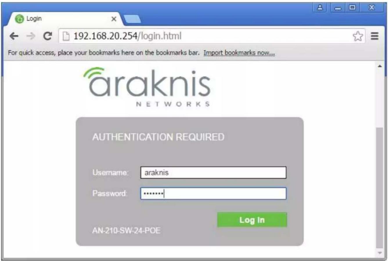
- Enter the switch's IP address (default is 192.168.20.254) in your browser and press ENTER.
- Enter username and password (default is "araknis" for both). Then click Log In.
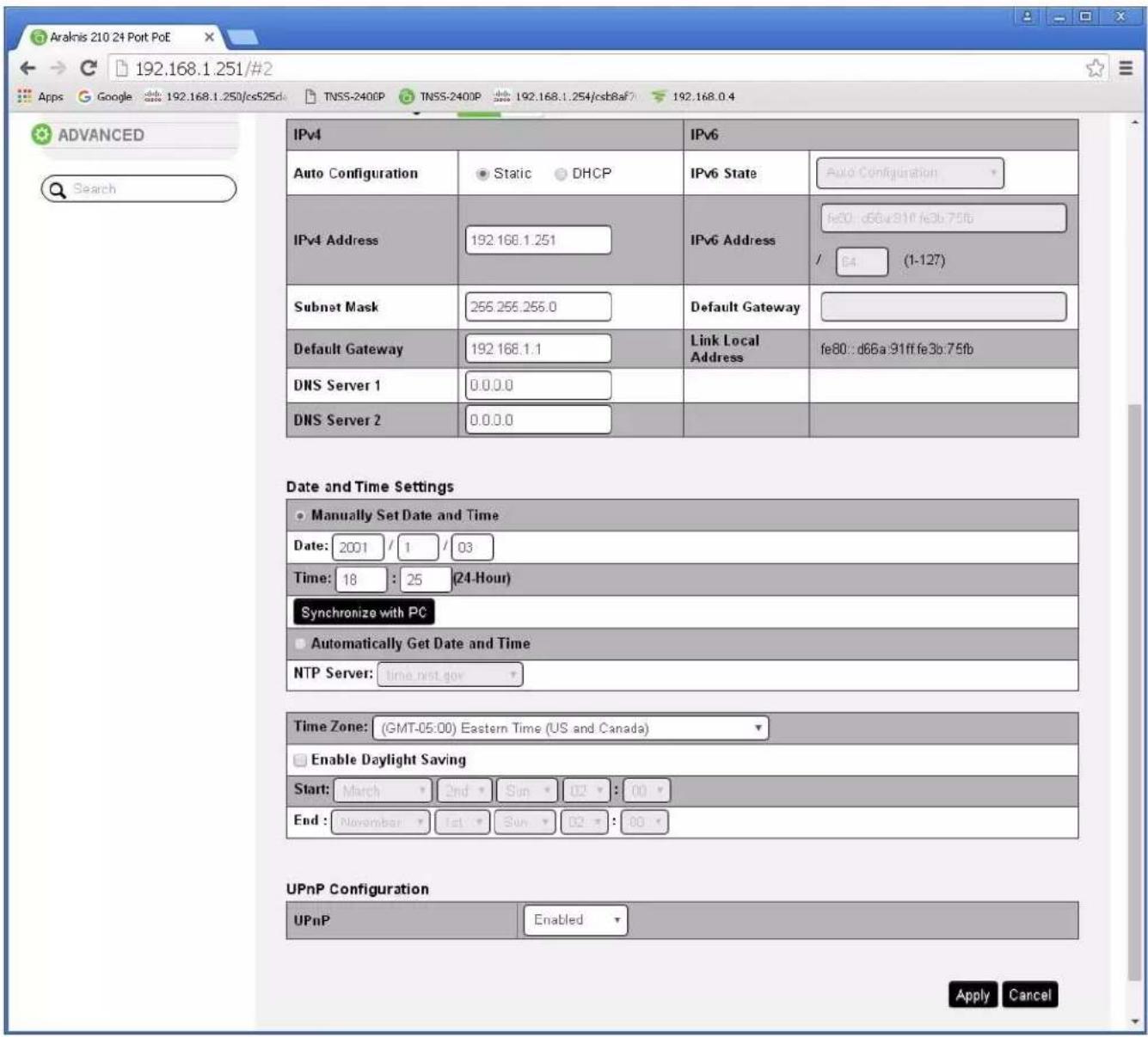
- Navigate to Settings -> System. Under IP Address Settings elect Static. Change an IP address to 192.168.1.251, Subnet Mask to 255.255.255.0, Default Gateway to 192.168.1.1 (in this case), and at the bottom click Apply. If you are setting up multiple network switches it is recommended to set first one to 192.168.1.251, second to 192.168.1.252, and so on, and each switch must be set individually same way as described below.
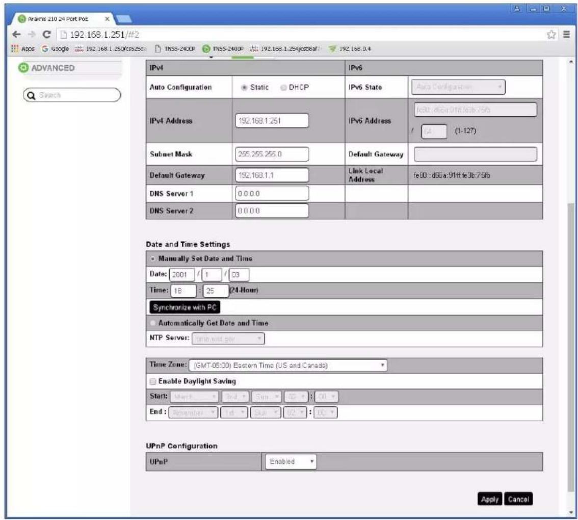
- Page will refresh. Configure your PC's IP address to the same range as the switch (default 192.168.1.xxx). Enter the switch's IP address (default is 192.168.1.251) in your browser and press ENTER.
- Make sure the settings remain as above.
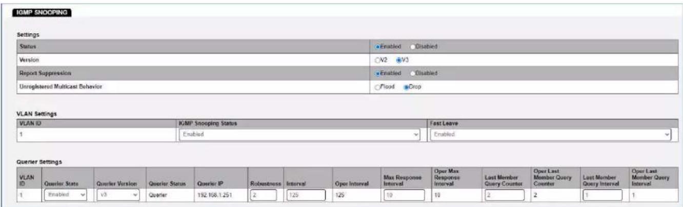
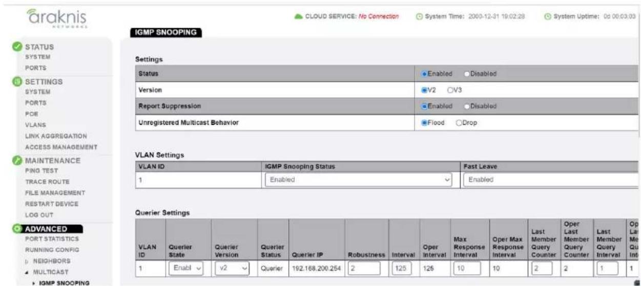
- Navigate to Advanced -> Multicast -> IGMP Snooping. Under Settings select Enable for Status, V3 for Version, and Enable for Report Suppression. Under VLAN Settings / VLAN ID 1 select Enable for IGMP
Snooping Status and Enable for Fast Leave. Under Querier Settings / VLAN ID 1 select Enable for Querier State, V3 for Querier Version and make sure all other setting are exactly as shown below. Click Apply.
- IMPORTANT: At this point all the displays should be displaying stable running video from the selected sources. If you do not have them displaying properly, than network switch is configured incorrectly.
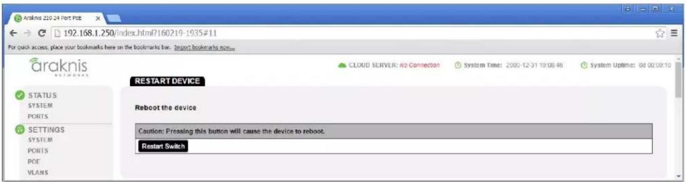
- Navigate to Maintenance -> Restart Device and click Restart Switch. After the reboot is complete, check all settings again.
- IMPORTANT: Now you can connect back you DHCP equipment (routers, servers and so on).
- Power down Araknis network switch and power it up back again. Wait for the whole system to start and until you can see video on your displays.
- Log in to your Araknis network switch again and make sure that IGMP settings are intact.
- Rescan your components with Key Digital Management Software and make sure HDMI video switch is functional.
- At this point your Araknis network switch is set and ready to use
- Connect your encoders, decoders, allow approx 3 mins for bootup, and perform a network scan using KD Management Software.
IGMP Setup Guide: Araknis 4K Systems (KD-IP822/922/1022)
- IMPORTANT: Disconnect all the DHCP devices like routers, servers from the Araknis network switch.
- Locate a pinhole "RESET" button at the front panel left bottom corner of your Araknis network switch. Using a paper clip press and hold a reset button for more than 10 seconds and then release. Wait while the device is restarted and ready to use (about 5min).
- IMPORTANT: At this point all the displays should be displaying distorted randomly flashing video images.
- Connect your PC to the Araknis network switch directly using a network cable.
- If you have not done yet, configure your PC's IP address to the same range as the switch (default 192.168.20.xxx).
- Enter the switch's IP address (default is 192.168.20.254) in your browser and press ENTER.
- Enter user name and password (default is "araknis" for both). Then click Log In.

- Navigate to Settings -> System. Under IP Address Settings elect Static. Change an IP address to 192.168.1.251, Subnet Mask to 255.255.255.0, Default Gateway to 192.168.1.1 (in this case), and at the bottom click Apply. If you are setting up multiple network switches it is recommended to set first one to 192.168.1.251, second to 192.168.1.252, and so on, and each switch must be set individually same way as described below.
- Page will refresh. Configure your PC's IP address to the same range as the switch (default 192.168.1.xxx). Enter the switch's IP address (default is 192.168.1.251) in your browser and press ENTER.
-
Make sure the settings remain as above.
-
Navigate to Advanced -> Multicast -> IGMP Snooping. Under Settings select Enable for Status, V2 for Version, Enable for Report Suppression, and Flood for Unregistered Multicast Behavior. Under VLAN Settings / VLAN ID 1 select Enable for IGMP Snooping Status and Enable for Fast Leave. Under Querier Settings / VLAN ID 1 select Enable for Querier State, V2 for Querier Version and make sure all other setting are exactly as shown below. Click Apply.
- Enter Settings -> Ports and set Jumbo Frame size to 9216 bytes, enabling the required 8K jumbo frame support feature.

- IMPORTANT: At this point all the displays should be displaying stable running video from the selected sources. If you do not have them displaying properly, then network switch is configured incorrectly.
- Navigate to Maintenance -> Restart Device and click Restart Switch. After switch is rebooted and back to normal log in again, check all the settings again.

- IMPORTANT: Now you can connect back you DHCP equipment (routers, servers and so on).
- Power down Araknis network switch and power it up back again. Wait for the whole system to start and until you can see video on your displays.
- Log in to your Araknis network switch again and make sure that IGMP settings are intact.
- Rescan your components with Key Digital Management Software and make sure HDMI video switch is functional.
- At this point your Araknis network switch is set and ready to use.
- Connect your encoders, decoders, allow approx 3 mins for bootup, and perform a network scan using KD Management Software.
Cisco Meraki series
After gaining access to the Cisco Dashboard, navigate to the following and applied settings as depicted:
Multicast settings
IGMP Snooping
IGMP snooping examines IGMP membership report messages to limit multicast traffic to the subset of interfaces on which interested hosts reside.
Switches/Stacks
IGMP snooping
Flood unknown multicast traffic
Default
Enabled
Disabled
Set multicast settings for another switch or stack
MTU configuration
MTU size
The Maximum Transmission Unit (MTU) is the maximum payload allowed in an ethernet frame.
Switches
MTU Size
Default MTU Size
9578

Set the MTU size for another set of switches
IGMP Setup Guide: Cisco SG and SF Series
4K Setup for SG Series
1080p Setup for SF Series
Note: SF Series is Compatible with KD-IP1080, KD-IP120 AV over IP Systems Only
- IMPORTANT: Disconnect all the DHCP devices like routers, servers from the Cisco network switch.
- Locate a pinhole "RESET" button at the front panel left bottom corner of your Cisco network switch. Using a paper clip press and hold a reset button for more than 10 seconds and then release. Wait while the device is restarted and ready to use (about 5min).
- IMPORTANT: Make sure the green "SYSTEM"LED next to the pinhole "RESET" button is flashing.
- IMPORTANT: At this point all the displays should be displaying distorted randomly flashing video images.
- Connect your PC to the Cisco network switch directly using a network cable.
- If you have not done yet, configure your PC's IP address to the same range as the switch (default 192.168.1.xxx).
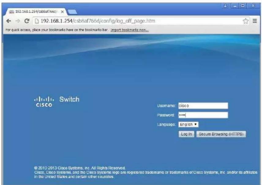
- Enter the switch's IP address in your browser and press ENTER (check the user manual for a default IP address - it is usually 192.168.1.254).
- Enter user name and password (check the user manual for a default user name and password; it is usually "cisco" for both). Then click Log In.
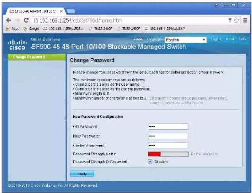
- Change Password screen will appear. Enter old and then new password two times as at the picture below and click Apply.
10. Getting Started screen will appear.
- Navigate to Configuration Wizards to access the Gettting Started Wizard, which will be used to set the desired IP address of the switch.
- Log in again using new password and new IP address.

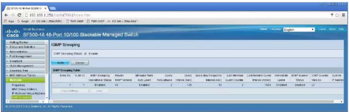
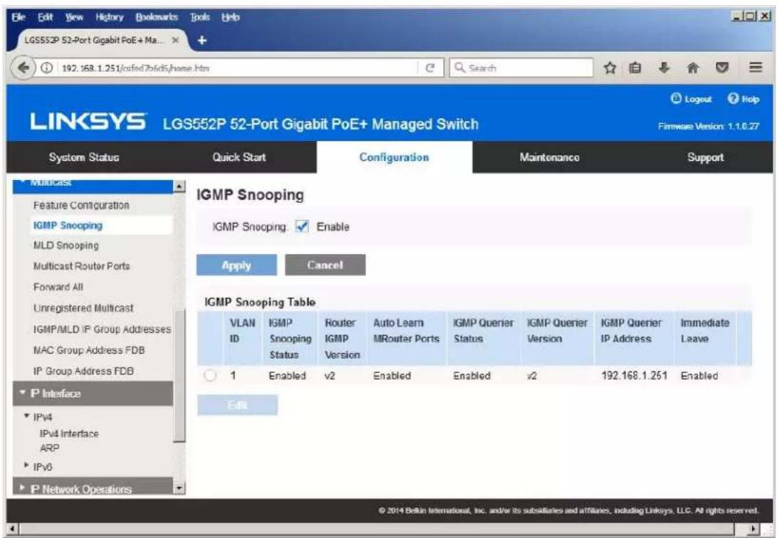
- Navigate to Multicast -> IGMP Snooping. Check the IGMP Snooping Status: Enable box and click Apply.

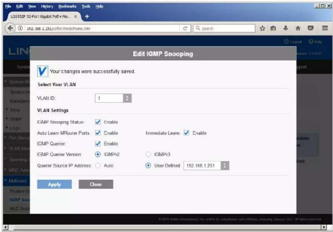
- Click on a radio button on the left and then click Edit. New window will appear. Select "1" for VLAN ID. Check Enable box under IGMP Snooping Status. Check Enable box under Immediate Leave. Check Enable box under IGMP Querier Status. Select User Defined next to Administrative Querier Source IP Address: and select 192.168.1.1. For IGMP Querier Version: select IGMPV3 for IP1080 system. If using IP922 system, select IGMPV2. Then click Apply and Close. Make sure all the setting are exactly as shown

- If using KD-IP922 system, enable jumbo frames in the Port Management section.

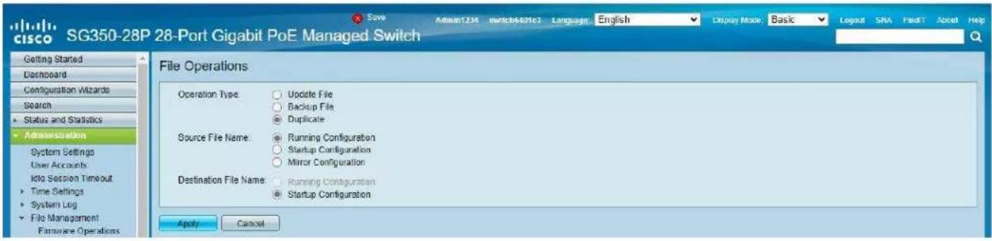
- On the top of the page click on flashing "x Save". For Source File Name: select Running configuration. For Destination File Name: select Startup configuration. Check the selections and make sure they are exactly as shown below. Click Apply.
- Click Apply to confirm.

18. Click Done.

- Power down Cisco network switch and power it up back again. Wait approx 5 minutes to reboot, and connection your Encoders, Decoders, and DHCP equipment (routers, servers and so on). After approx 2 minutes of bootup for the AV over IP equipment, you should see image on your displays
- Log in to your Cisco network switch again and make sure that IGMP settings are intact:
- Rescan your components with Key Digital Management Software and make sure HDMI video switch is functional.
- At this point your Linksys network switch is set and ready to use.
- Connect your encoders, decoders, allow approx 3 mins for bootup, and perform a network scan using KD Management Software.
IGMP Setup Guide: Cisco C3850 Series
4K Systems (KD-IP822/922/1022)
Cisco Catalyst 3850 series
This guide describes how to use Express Setup to initially configure your Catalyst 3850 switch. We have modified original Express Setup guide from Cisco to help out you install it easily. For more installation and configuration information, see the Catalyst 3850 documentation on Cisco.com.
Running Express Setup & Configuration Setup for KD-IP822, KD-IP922, KD-IP1022
Use Express Setup to enter the initial IP information. This action enables the switch to connect to local routers and the Internet. You can access the switch through the IP address for further configuration.
Note : Even you already finish Express Setup on your switch, please check every step one by one.
| Step 1 | Make sure that nothing is connected to the switch. |  |
| Step 2 | During Express Setup, the switch acts as a DHCP server. If your PC or laptop has a static IP address, temporarily change your PC or laptop settings to DHCP.Note. Do not connect LAN cable from your PC or laptop to Cisco's switch until Step 7. |  |
| Step 3 | Install the power supply modules. See the “Power Supply Installation” chapter in the Catalyst 3850 Switch Hardware Installation Guide for instructions.http://www.cisco.com/go/cat3850_hw | |
| Step 4 | Power the switch.AC power switches: Plug the AC power cord into the switch power supply and into a grounded AC outlet.DC power switches: See the wiring instructions in Step3 |  |
| Step 5 | Observe the POST results. Approximately 30 seconds after the switch powers on, it begins the power-on self-test (POST), which can take up to 5 minutes to complete.During POST, the SYSTEM LED blinks green. When POST is complete, the SYSTEM LED turns solid green.The ACTV LED is green if the switch is acting as the active switch.Note Before going to the next step, wait until POST is complete.Troubleshooting:If the SYST LED does not turn solid green, or turns amber, the switch failed the POST. Contact your Cisco representative or reseller. | |
| Step 6 | Press and hold the Mode button until all the LEDs next to the Mode button turn green.You might need to hold the button for more than 3 seconds.The switch is now in Express Setup mode. | 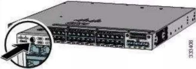 |
| Troubleshooting:If the LEDs next to the Mode button blink when you press the button, release it. Blinking LEDs mean that the switch is already configured and cannot go into Express Setup mode. For more information, see the "Resetting the Switch" section. | ||
| Step 7 | Connect a Category 5e/6 Ethernet cable to first port on the front panel of Cisco Switch.Connect the other end of the cable to the Ethernet port on your PC or laptop.Wait until the port LEDs on the switch and your PC or laptop or laptop are green or blinking green. Green LEDs indicate a successful connection.Troubleshooting:If the port LEDs do not turn green after about 30 seconds, make sure that: You are using an undamaged Category 5 or 6 Ethernet cable(Do not connect console ports) | 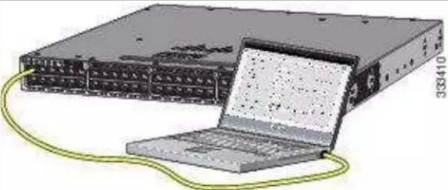 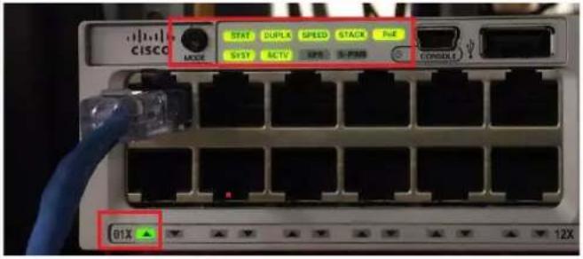 |
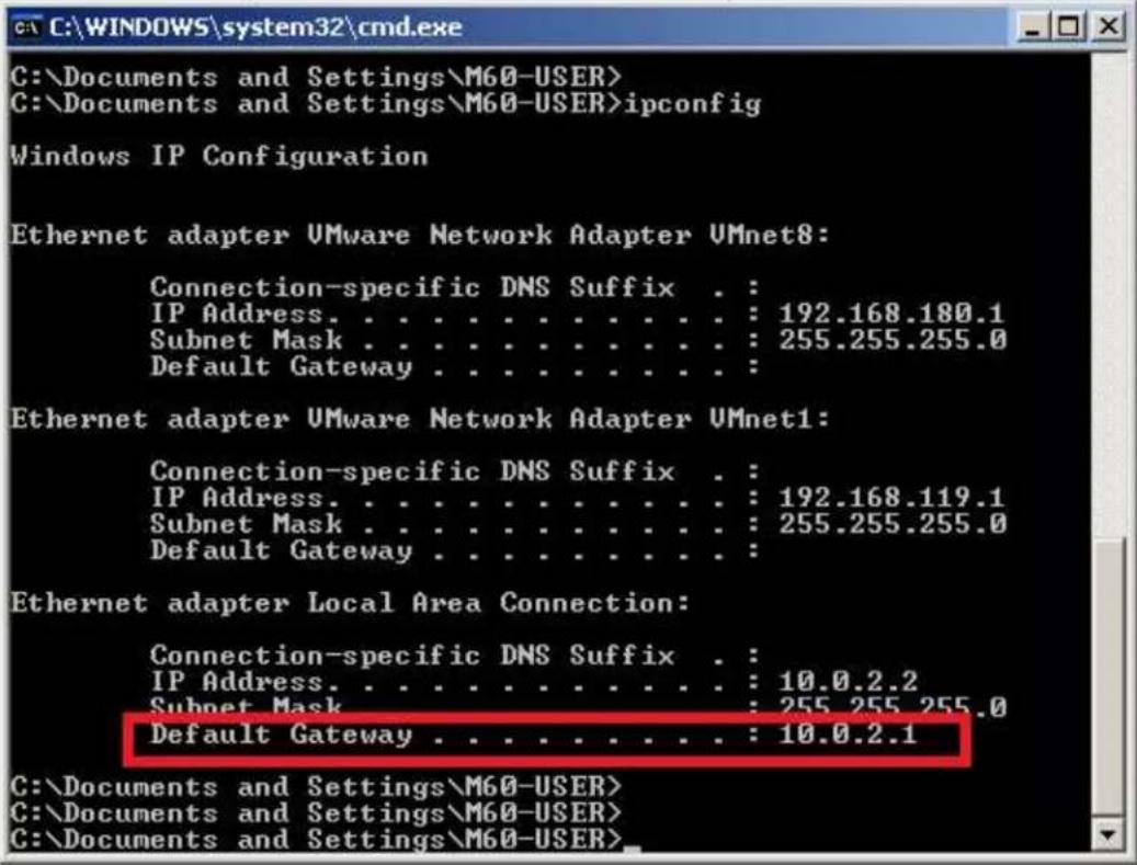
| Step 8 | Run command shell on your PC or laptop and enter “ipconfig” on the command line. You will get Windows IP configuration and find IP address of Default Gateway.Note. According to Express Setup from Cisco, it said “10.0.01” is default IP address. But it’s not correct for all Cisco Catalyst 3850 series. It looks default IP address will be varied depend on Cisco Switches. | |
 | ||
| Step 9 | Start a browser session on the PC or laptop, and enter the IP address of your Default Gateway.Note: As I mentioned on Step8, your IP address of Default Gateway may differ with our IP address.When a pop-up dialog window “Connect to 10.0.2.1” appear,skip the User name and enter the default password, “cisco”Troubleshooting:If the Express Setup window does not appear, make sure that any browser pop-up blockers or proxy settings are disabled and that any wireless client is disabled on your PC or laptop. |  |
| Step 10 | Click “Continue” button on Startup Report page.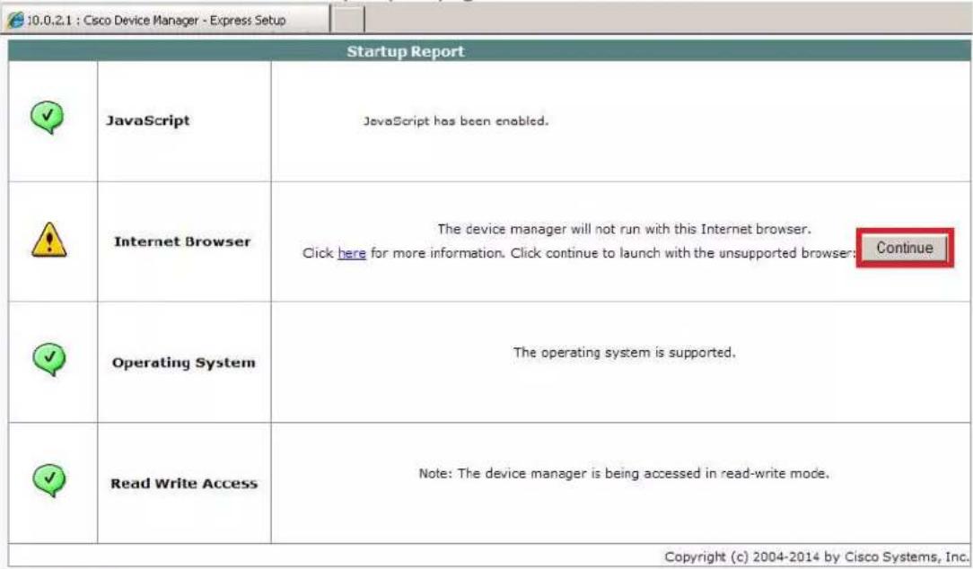 | |
| Step 11 | Select the Basic Settings on the Express Setup window and change the network settings as you like, then go Step12. | |
Note. Please do not click "Submit" button in this step.
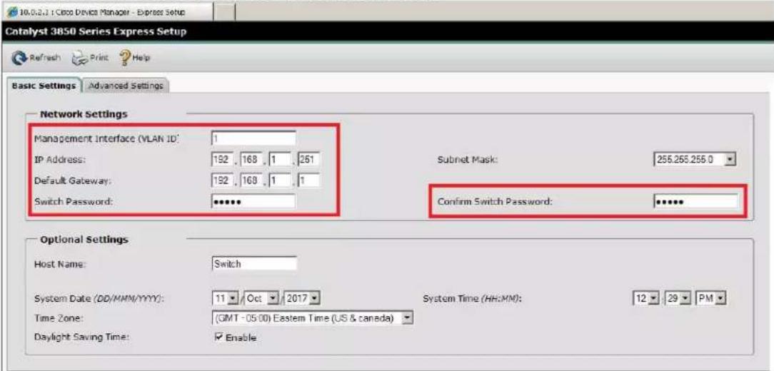
Step 12
Select the Advanced Settings tab on the Express Setup window
- In the Telnet Access field, click Enable to use Telnet to manage the switch by using the command-line interface (CLI). If you enable Telnet access, you must enter a Telnet password.
- In the Telnet Password field, enter a password. The Telnet password can be from 1 to 25 alphanumeric characters, is case sensitive, allows embedded spaces, but does not allow spaces at the beginning or end. In the Confirm Telnet Password field, reenter the Telnet password.
And click Submit to save your changes and to complete the initial setup.

| Step 13 | After you clickSubmit:The switch is configured and exitsExpress Setup mode.The browser displays a warning messageand tries to connect with the earlierswitch IP address. Typically, connectivitybetween the PC or laptop and the switchis lost because the configured switch IPaddress is in a different subnet from theIP address on the PC or laptop.Now, change IP address of your PC or laptop tostatic IP address in same subnet of the Switch. | 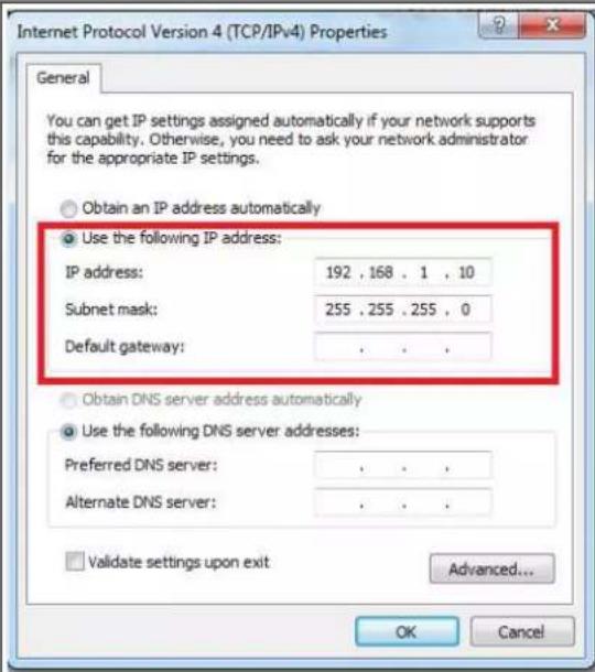 |
| Step 14 | To configuring Multicast IGMP Snooping and Jumbo Frame setting at the switch for KD-IP922 devices,you have to connect to the Switch via Telnet.Note. To access Telnet, you can use PuTTY or Tera Term software.We recommend to use Tera Term software and you can download it as below link.https://osdn.net/projects/ttssh2/downloads/68252/teraterm-4.96.exe/Run Tera Term software, and press Alt + N keys to open new connection.14-1. Select “TCP/IP” on Tera Term:New Connection Window.14-2. Type the IP address of the Switch at the field of Host: Ex) 192.168.1.25114-3. Type 23 at the field of TCP Port# and select “Telnet”.14-4. Then click OK button. | |
![Tera Term - [disconnected] VT File Edit Setup Control Window Help Tera Term: New connection TCP/IP Host: 192.168.1.251 TCP port#: 23 Protocol: UNSPEC Telnet Serial Port: OK Cancel Help](/content/2026/05/1061493/images/79878379a3c53ff0faa87c38de9833f97d50ebd7ac7b2ba5620a76a0105b445c.jpg)
Step 15
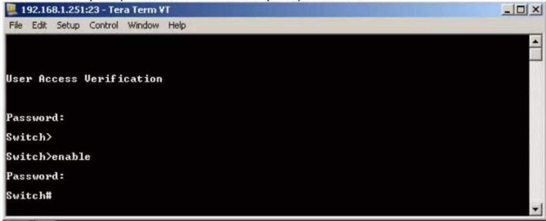
When you connect to the switch via Telnet successfully, you have to log in to Telnet server of the switch.
15-1. Enter your Telnet password you assigned at Step12 if prompted.
15-2. Enter "enable" on Switch> prompt to enable privileged EXEC mode
15-3. Enter your Telnet password once again.
Then 'Switch>' prompt will turn into 'Switch#' prompt as below.
Step 16
To Enable Jumbo Frame for IP922.
Note: IP922 requires Jumbo Frame(8K) for video/audio transmission via 1G-BaseT with the Switch.
16-1. Enter "configure terminal" on Switch# prompt
16-2. Enter "system mtu 9000" on Switch(config)# prompt
16-3. Enter "end" on Switch(config)# prompt
16-4. Enter "copy running-config startup-config" on Switch# prompt
16-5. Press Enter key on the question of "Destination filename [startup-config]?"
![192.168.1.251:23 - Tera Term VT File Edit Setup Control Window Help Switch# Switch#configure terminal Enter configuration commands, one per line. End with CNTL/Z. Switch(config)#system mtu 9000 Global Ethernet MTU is set to 9000 bytes. Note: this is the Ethernet payload size, not the total Ethernet frame size, which includes the Ethernet header/trailer and possibly other tags, such as ISL or 802.1q tags. Switch(config)#end Switch#copy running-config startup-config Destination filename [startup-config]? Building configuration... Compressed configuration from 3614 bytes to 1620 bytes[OK] Switch# Switch# Step 17 To confirm Jumbo Frame setting on the switch. 17-1. Enter "show interfaces vlan 1" on Switch# prompt You can check MTU 9000 bytes in the status of Vlan1 interface](/content/2026/05/1061493/images/ec20d2541e95371dd622697144107b1cc6e0aea288ec0a81080a2491f19bd09c.jpg)
| 192.168.1.251:23 - Tera Term VTFile Edit Setup Control Window HelpSwitch#show interfaces vlan 1Ulan1 is up, line protocol is upHardware is Ethernet SUI, address is 00a3.d19b.2347 (bia 00a3.d19b.2347)Internet address is 192.168.1.251/24MTU 9000 bytes, BW 1000000 Kbit/sec, DLY 10 usec,reliability 255/255, txload 1/255, rxload 118/255Encapsulation ARPA, loopback not setKeepalive not supportedARP type: ARPA, ARP Timeout 04:00:00Last input 00:00:00, output never, output hang neverLast clearing of "show interface" counters neverInput queue: 0/75/0/0 (size/max/drops/flushes); Total output drops: 0Queueing strategy: fifoOutput queue: 0/40 (size/max)5 minute input rate 466196000 bits/sec, 10971 packets/sec | |
| Step18 | To Enable Multicast IGMP Snooping for IP922.Note: IP922 requires Multicast IGMP Snooping for matrix switch configuration.18-1. Enter "configure terminal" on Switch# prompt18-2. Enter "ip igmp snooping" on Switch(config)# prompt18-3. Enter "ip igmp snooping vlan 1" on Switch(config)# prompt18-4. Enter "ip igmp filter" on Switch(config)# prompt18-5. Enter "ip igmp snooping tcn query solicit" on Switch(config)# prompt18-6. Enter "ip igmp snooping querier" on Switch(config)# prompt18-7. Enter "ip igmp snooping querier version 2" on Switch(config)# prompt18-8. Enter "ip igmp snooping vlan 1 immediate-leave" on Switch(config)# prompt18-9. Enter "end" on Switch(config)# prompt18-10. Enter "copy running-config startup-config" on Switch# prompt18-11. Press Enter key on the question of "Destination filename [startup-config]?"Now, we are all set.192.168.1.251:23 - Tera Term VTFile Edit Setup Control Window HelpSwitch#configure terminalEnter configuration commands, one per line. End with CNTL/Z.Switch#Switch#ip igmp snoopingSwitch#ip igmp snooping vlan 1Switch#ip igmp filterSwitch#ip igmp snooping tcn query solicitSwitch#ip igmp snooping querierSwitch#ip igmp snooping querier version 2Switch#ip igmp snooping vlan 1 immediate-leaveSwitch#Switch#endSwitch#Switch#copy running-config startup-configDestination filename [startup-config]?Building configuration...Compressed configuration from 3737 bytes to 1689 bytes[OK]Switch#Switch# |
| Step 19 | To confirm multicast IGMP Snooping setting on the switch.19-1. Enter "show ip igmp snooping detail" on Switch# promptYou can check global IGMP Snooping configuration on the switch. |

Connect your encoders, decoders, allow approx 3 mins for bootup, and perform a network scan using KD Management Software.
D-Link DGS-3630 Series
Network Setup Guide
Login to the switch:
- Plug an Ethernet cable into any of the ports of the switch
- Plug the other end into the Ethernet port of your computer
-
Power on the switch
-
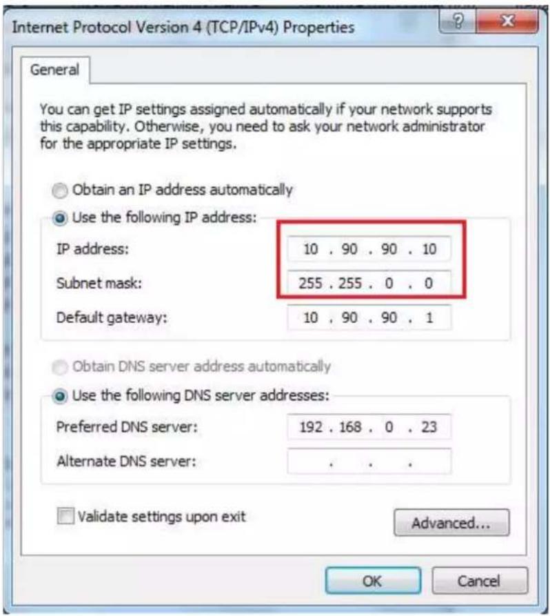
Check to see that the IP address of the computer is within this network Subnet: 10.90.90.xxx ("xxx" ranges 1\~254). For example, 10.90.90.10
- Open the Web browser and enter 10.90.90.90 (default IP address of D-Link DGS-3630-52PC). The login window appears as below.
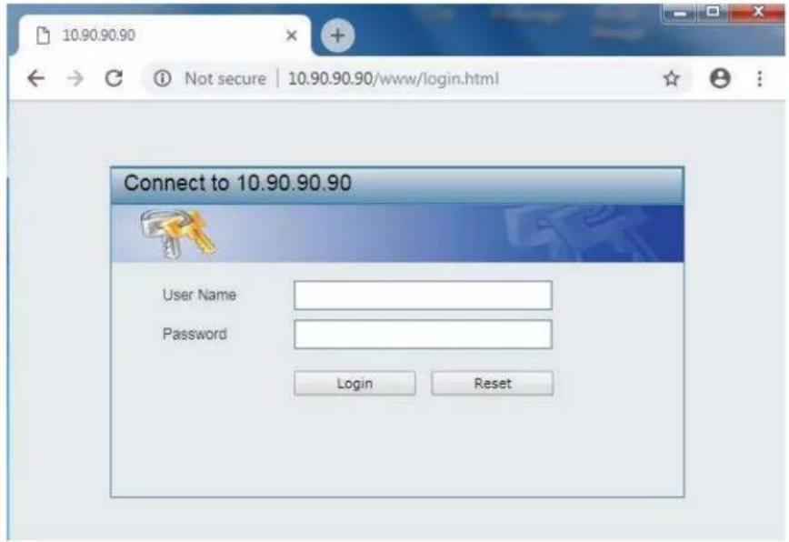
- Leave the user name and password fields empty. They are NOT required. Click "Login" to login to the switch configuration window.
Enable Jumbo Frame:
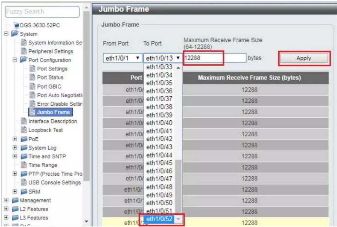
- Find System -> Port Configuration -> Jumbo Frame in the menu on left side of the window. (IP922 requires Jumbo Frame(8K) for video/audio transmission via 1G-BaseT).

- Select the last 52 port "eth 1/0/52" in the menu on To Port, then enter "12288" in Maximum Frame Size on the right side of the Jumbo Frame window as below. And then click "Apply" button.

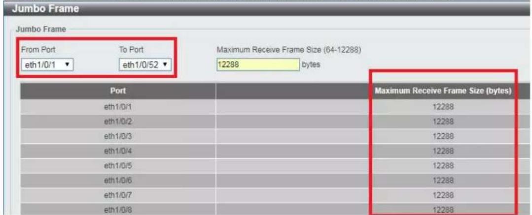
- After applying, you should see Maximum Receive Frame Size 12288 for all ports as below.
Enable IGMP Snooping:
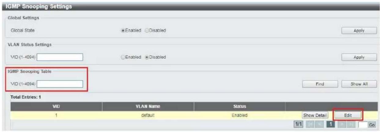
- Find L2 Features -> L2 Multicast Control -> IGMP Snooping -> IGMP Snooping Settings in the menu on left side of the window. (KD-IP922 requires IGMP Snooping for multicasting video/audio transmission via 1G-BaseT). Check the Global State Enabled box of Global Settings in IGMP Snooping Settings window as below. Click "Apply" button on the right side of IGMP Snooping Settings window.

- To add VLAN of the IGMP Snooping at the switch, enter "1" in VID of VLAN Status Settings. (VLAN must be added in IGMP Snooping). Then select "Enabled" and click "Apply" button.

- Click "Edit" button in IGMP Snooping Settings window.
-
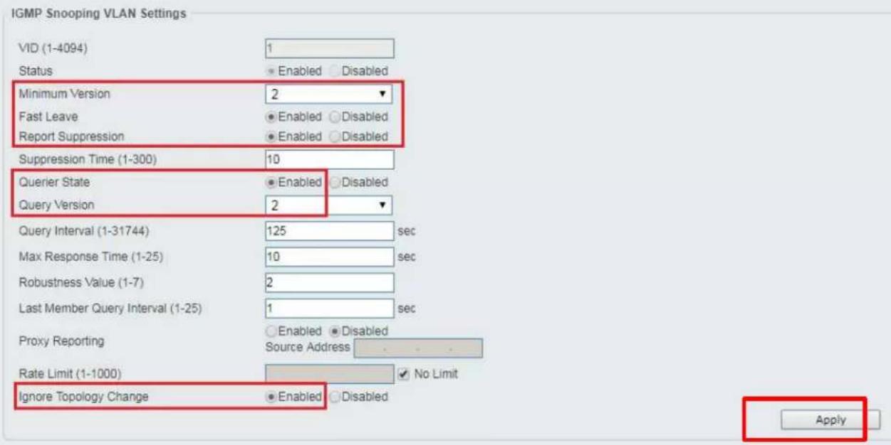
In the IGMP Snooping VLAN Settings window, select below options as depicted below in red and then click "Apply" button:
-
Minimum Version: 2
- Fast Leave: Enabled
- Report Suppression: Enabled
- Querier State: Enabled
- Query Version: 2
- Ignore Topology Change: Enabled
IGMP Snooping VLAN Settings
Network IP Settings:
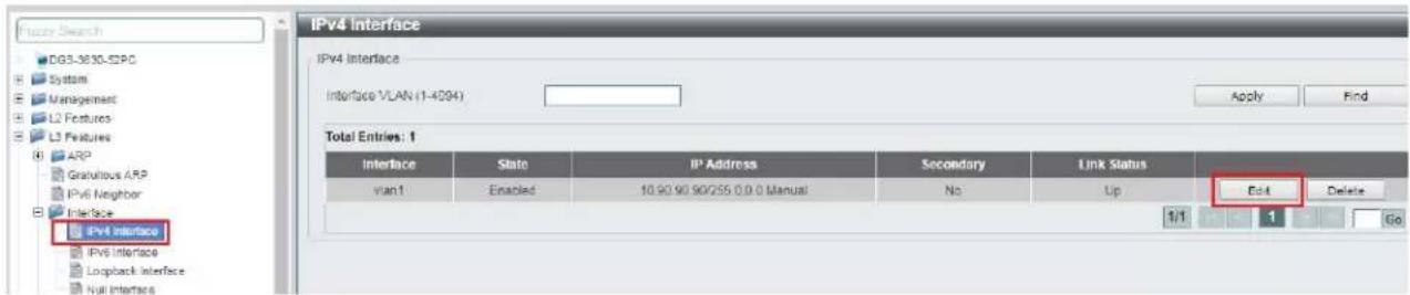
- Find L3 Features -> Interface -> IPv4 Interface. Select "Edit" button.
This D-Link switch series can be set to IP address range 10.x.x.x. ONLY.
If you use a single network switch, you may not need to change network IP settings. But if you are stacking network switches (connecting multiple network switches through D-Link 10G fiber cables), it is recommended to set first on to 10.90.90.91, second to 10.90.90.92, and so on.
Set Get IP From "Static", set Subnet Mask to 255.0.0.0 and click Apply.
If you change an IP address, the page will be refreshed and you will need to log in again using new IP address, same user name and password. If you did not change IP address just continue to the next step. Make sure your screen looks exactly like pictured below.

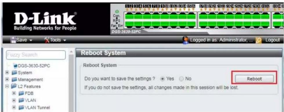
- To save all Running Configurations to Startup-Configuration, Find Save → Save Configuration in the menu on top of the window. Then click "Apply" button in Save Running Configuration to startup-config window.

- To reboot the switch, Find Tool → Reboot System in the menu on top of the window. Then click "Reboot" button in Reboot System window. The switch will be rebooted automatically.

Edgecore AS4610-54T / Cumulus Linux version 3.7.15
For advanced users only – support is limited for this model!
Cumulus Linux was verified using version v3.7.15. The below commands creates VLAN 2 and configures a network bridge for IGMP snooping.
net del all
net add dns nameserver ipv4 10.105.104.1
net add time zone Etc/UTC
net add time ntp server 0.cumulusnetworks.pool.ntp.org iburst
net add time ntp server 1.cumulusnetworks.pool.ntp.org iburst
net add time ntp server 2.cumulusnetworks.pool.ntp.org iburst
net add time ntp server 3.cumulusnetworks.pool.ntp.org iburst
net add time ntp source eth0
net add snmp-server listening-address localhost
net add interface swp1-49 igmp
net add interface swp49 igmp query-max-response-time 10
net add routing defaults datacenter
net add routing service integrated-vtysh-config
net add routing log syslog informational
net add username cumulus nopassword
net add ptp global slave-only no
net add ptp global priority1 255
net add ptp global priority2 255
net add ptp global domain-number 0
net add ptp global logging-level 5
net add ptp global path-trace-enabled no
net add ptp global use-syslog yes
net add ptp global verbose no
net add ptp global summary-interval 0
net add ptp global time-stamping
net add bridge bridge mld-version 2
net add bridge bridge ports
swp1,swp2,swp3,swp4,swp5,swp6,swp7,swp8,swp9,swp10,swp11,swp12,swp13,swp14,swp15,swp16,swp17,swp18,swp19,swp20,swp21,swp22,swp23,swp24,swp25,swp26,swp27,swp28,swp29,swp30,swp31,swp32,swp33,swp34,swp35,swp36,swp37,swp38,swp39,swp40,swp41,swp42,swp43,swp44,swp45,swp46,swp47,swp48,swp49
net add bridge bridge pvid 1
net add bridge bridge vids 2
net add bridge bridge vlan-aware
net add interface eth0 ip address 10.105.104.253/24
net add interface eth0 ip gateway 10.105.104.1
net add interface swp1-49 bridge pvid 2
net add interface swp1-49 bridge vids 2
net add interface swp1-49 mtu 9216
net add interface swp49 link speed 10000
net add dot1x radius accounting-port 1813
net add dot1x max-number-stations 4
net add dot1x radius authentication-port 1812
net add dot1x eap-reauth-period 0
net add dot1x mab-activation-delay 30
net commit
In addition, manually add the following line to the bridge configuration in "/etc/network/interfaces"
bridge-mclmi 30
Modify the commands as needed to best fit the network environment. This configuration enables port 49 for uplink to another switch to expand the system.
IGMP Setup Guide: Engenius 1080p Systems (KD-IP1080, KD-IP120)
- It is recommended to reset the switch to factory defaults before configuring for multicast operation. Power up the device, wait for about 2 minutes, using a paper clip press and hold a reset button for more than 10 seconds and then release. After device is rebooted power down and then power up the device. Wait while the device is restarted and ready to use.
- Connect your PC to the switch directly using a network cable.
- Configure your PC's IP address to the same range as the switch (default 192.168.0.xxx).
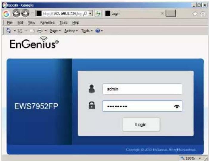
- Enter the switch's IP address (default is 192.168.0.239) in your browser and press ENTER.
- Enter user name and password (default is "admin" and "password"). Then click Log In.
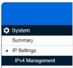
- On the left select Switch. Navigate to System -> IP Settings -> IPv4. Under Auto Configuration select Static. Change an IP address to 192.168.1.250, Subnet Mask to 255.255.255.0, Default Gateway to 192.168.1.1 (in this case), and at the bottom click Apply.

-
Page will refresh. Configure your PC's IP address to the same range as the switch (default 192.168.1.xxx). Enter the switch's IP address (default is 192.168.1.250) in your browser and press ENTER. Log in again with the same user name /password.
-
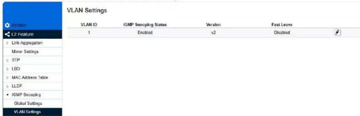
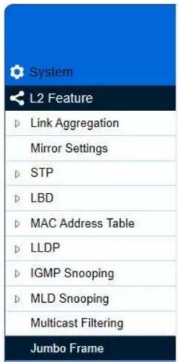
On the left select Switch. Navigate to L2 Feature -> IGMP Snooping -> Global Settings. Under Status select Enabled, under Version: V2 and under Report Suppression: Enabled. Click Apply.

- Navigate to L2 Feature -> IGMP Snooping -> VLAN Settings. Click on Edit button on the right in the VLAN ID 1 line. Under IGMP Snooping Status select Enabled, under Fast Leave select Enabled. Click check mark button to apply settings.
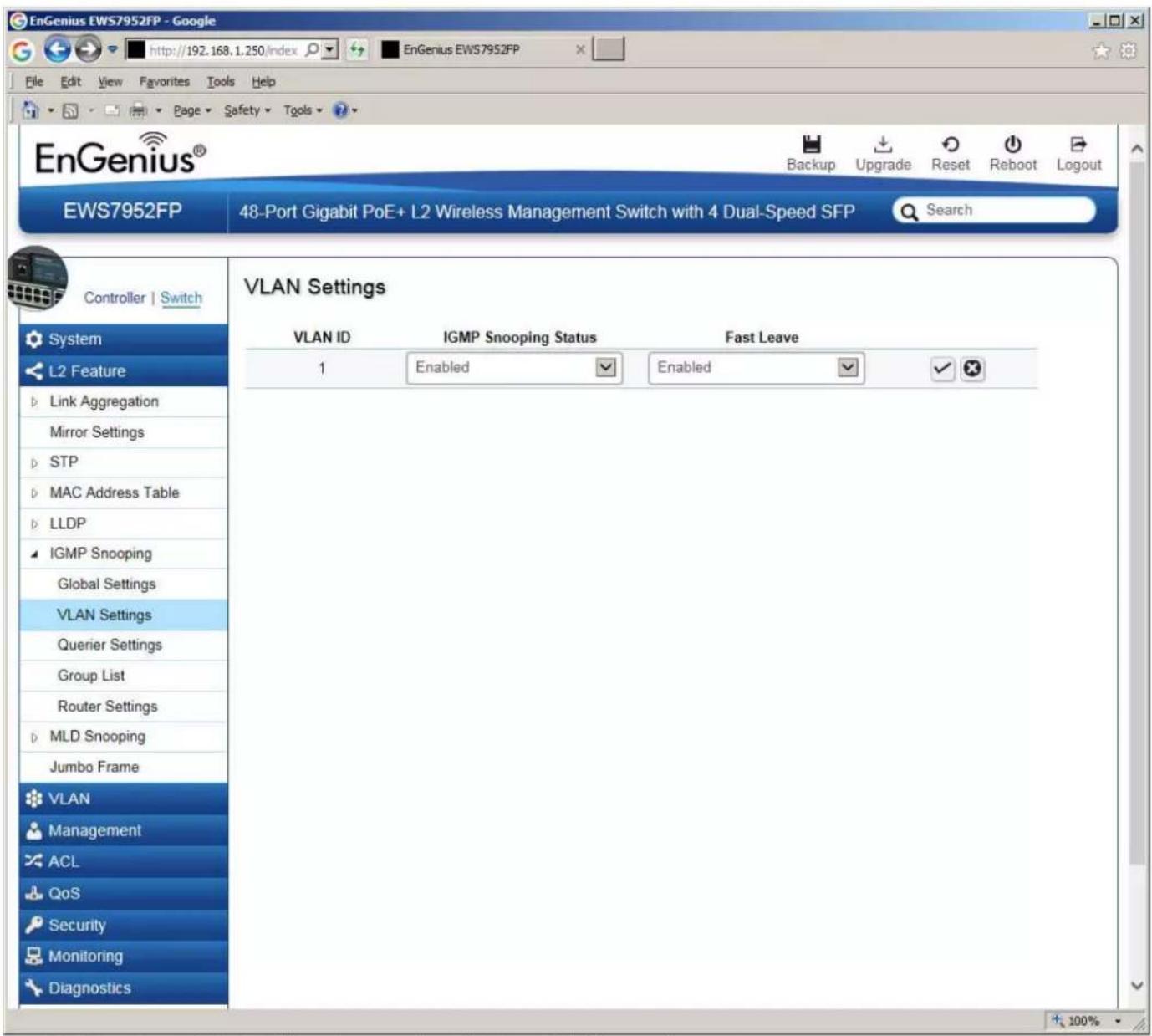
- Now the switch should work properly with IP audio/video equipment.
- Connect your encoders, decoders, allow approx 3 mins for bootup, and perform a network scan using KD Management Software.
Linksys LGSxxxMPC setup guide for KD-IP922, KD-IP822, and KD-IP1080 systems
Recommended firmware version: 1.00.01.03
\*Steps related to stacking multiple switches are in red\*
- Ensure that your PC is set to a static IP address that is within the subnet of the network switch (192.168.1.xyz)
- Connect to the network switch via its default IP address – 192.168.1.251. The default login credentials are:
Username: "admin"
Password: "admin"
After connecting, change the password to gain access to the switch.

- Set the IP address of the switch to the desired address. This setting is accessed via System -> IP settings -> IPv4 Management.
3a. If stacking multiple network switches, each will require a unique IP address.
IPv4 Management

- Enable IGMP snooping. This setting is accessed via L2 feature -> IGMP Snooping -> Global settings. Ensure all settings are in line with the image.

IGMP Snooping

- Enable IGMP snooping for your VLAN. This setting is accessed via L2 feature -> IGMP Snooping -> VLAN settings. Use IGMP version 2. VLAN 1 is used by default. Other VLANs are compatible as well.
5a. Ensure Fast Leave is disabled when stacking.
- Enable the IGMP querier This setting is accessed via L2 feature -> IGMP Snooping -> Querier settings.
6a. Select one switch to be the IGMP querier. Enable the querier on this switch only and disable the IGMP querier on all other switches.

| Querier Settings | |||||||
| VLAN ID | Querier State | Querier Version | Querier Status | Interval | Max Response Interval | Startup Query Counter | Startup Query Interval |
| 1 | Enabled | v2 | Querier | 126 | 12 | 2 | 15 |
- Set the frame size to its maximum value of 10240. L2 feature -> Jumbo Frame
Jumbo Frame

8. Enable Multicast Filtering. L2 feature -> Multicast Filtering
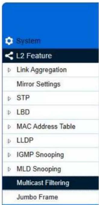
Multicast Filtering

- Verify all settings are applied after power cycling. The switch should now be ready to use.
- Connect your encoders, decoders, allow approx 3 mins for bootup, and perform a network scan using KD Management Software.
IGMP Setup Guide: Linksys 1080p Systems (KD-IP1080, KD-IP120)
- IMPORTANT: Disconnect all the DHCP devices like routers, servers from the Linksys network switch.
- Locate a pinhole "RESET" button at the front panel left bottom corner of your Linksys network switch. Using a paper clip press and hold a reset button for more than 10 seconds and then release. Wait while the device is restarted and ready to use (about 5min).
- IMPORTANT: Make sure the blue "SYSTEM"LED next to the pinhole "RESET" button is flashing.
- IMPORTANT: At this point all the displays should be displaying distorted randomly flashing video images.
- Connect your PC to the Linksys network switch directly using a network cable.
- If you have not done yet, configure your PC's IP address to the same range as the switch (default 192.168.1.xxx).
- Enter the switch's IP address in your browser and press ENTER (check the user manual for a default IP address - it is usually 192.168.1.251).
- Enter user name and password (check the user manual for a default user name and password; it is usually "admin" for both). Then click Log In.

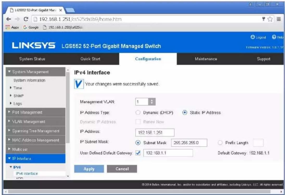
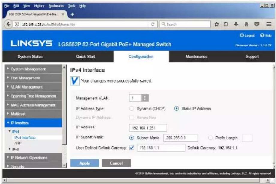
- Navigate to Configuration -> IP Interface -> IPv4-> IPv4 Interface. Select Static IP Address. IP address can be changed by the administrator depending on the network configuration. If you are using multiple network switches it is recommended to set first one to 192.168.1.251, second to 192.168.1.252, and so on (we will leave the IP address unchanged). Set Subnet Mask to 255.255.255.0, set User Defined Default Gateway to 192.168.1.1 (in this case), make sure that Management VLAN is set to "1" and click Apply. If you changed an
IP address page will refresh and you will need to log in again using new IP address, same user name and password. If you did not change IP address just continue to the next step.
- Make sure your screen looks exactly like pictured below.
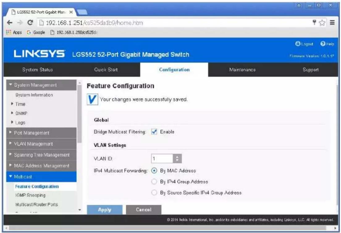
- Navigate to Multicast -> Future Configuration. Select Enable under Bridge Multicasting Filtering and click Apply.
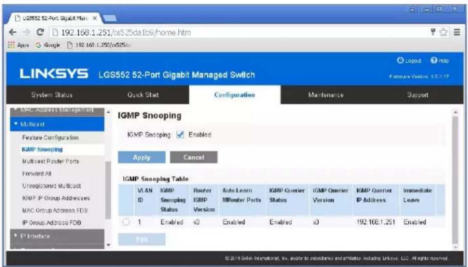
- Navigate to Multicast -> IGMP Snooping. Select Enable under IGMP Snooping, click Apply.

- Click on radio button and click Edit. Edit IGMP Snooping window will appear. Make sure VLAN ID <1> is selected. Enable all the settings as shown below. Select IGMP v3 as IGMP Querier Version, Click Apply and then Close.

- Refresh your browser, go to IGMP Snooping tab and make sure you have an image as below:

- IMPORTANT: At this point all the displays should be displaying stable running video from the selected sources. If you do not have them displaying properly, than network switch is configured incorrectly.
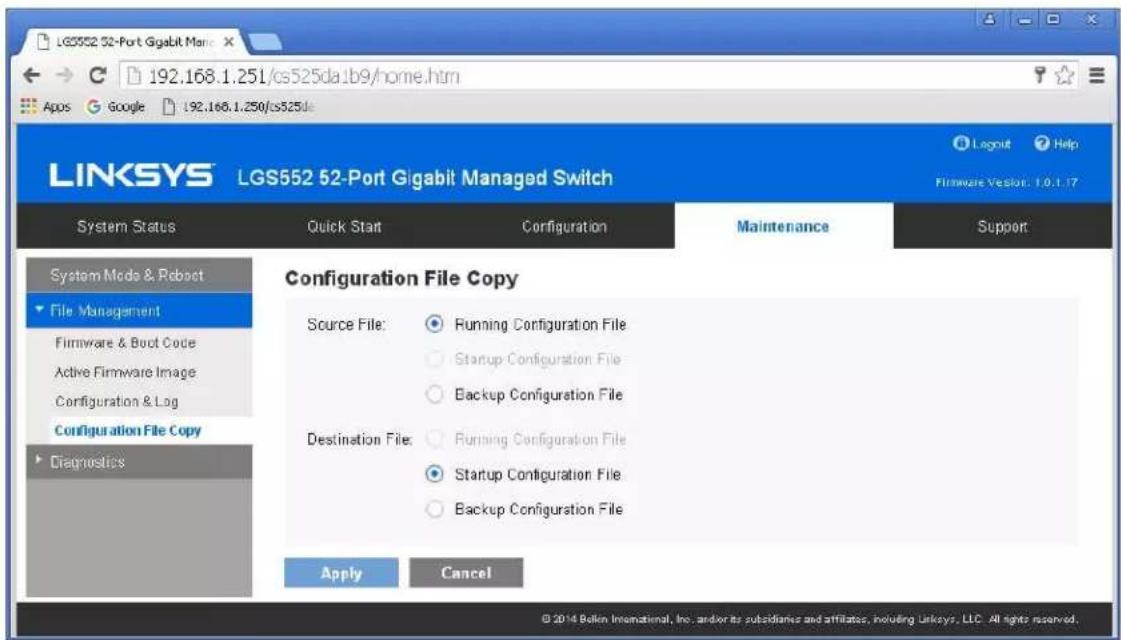
- Navigate to Maintenance -> File Management -> Configuration File Copy. Select radio buttons as shown below, click Apply. This will save current configuration and will apply this configuration every time switch is powered up.
- IMPORTANT: Now you can connect back you DHCP equipment (routers, servers and so on).
-
Power down Linksys network switch and power it up back again. Wait for the whole system to start and until you can see video on your displays.
-
Log in to your Linksys network switch again and make sure that IGMP settings are intact:

- Rescan your components with Key Digital Management Software and make sure HDMI video switch is functional.
- At this point your Linksys network switch is set and ready to use.
- Connect your encoders, decoders, allow approx 3 mins for bootup, and perform a network scan using KD Management Software.
IGMP Setup Guide: Linksys 4K Systems (KD-IP822, KD-IP922, KD-IP1022)
- IMPORTANT: Disconnect all the DHCP devices like routers, servers from the Linksys network switch.
- Locate a pinhole "RESET" button at the front panel left bottom corner of your Linksys network switch. Using a paper clip press and hold a reset button for more than 10 seconds and then release. Wait while the device is restarted and ready to use (about 5min).
- IMPORTANT: Make sure the blue "SYSTEM"LED next to the pinhole "RESET" button is flashing.
- IMPORTANT: At this point all the displays should be displaying or flashing Key Digital logo with information stamp.
- Connect your PC to the Linksys network switch directly using a network cable.
- If you have not done yet, configure your PC's IP address to the same range as the switch (default 192.168.1.xxx).
- Enter the switch's IP address in your browser and press ENTER (check the user manual for a default IP address - it is usually 192.168.1.251).
- Enter user name and password (check the user manual for a default user name and password; it is usually "admin" for both). Then click Log In.

- Navigate to Configuration -> IP Interface -> IPv4-> IPv4 Interface. Select Static IP Address. IP address can be changed by the administrator depending on the network configuration. If you are using multiple network switches it is recommended to set first one to 192.168.1.251, second to 192.168.1.252, and so on (we will leave the IP address unchanged). Set Subnet Mask to 255.255.0.0, set User Defined Default Gateway to 192.168.1.1 (in this case), make sure that Management VLAN is set to "1" and click Apply. If you changed an
IP address page will refresh and you will need to log in again using new IP address, same user name and password.
- Make sure your screen looks exactly like pictured below.
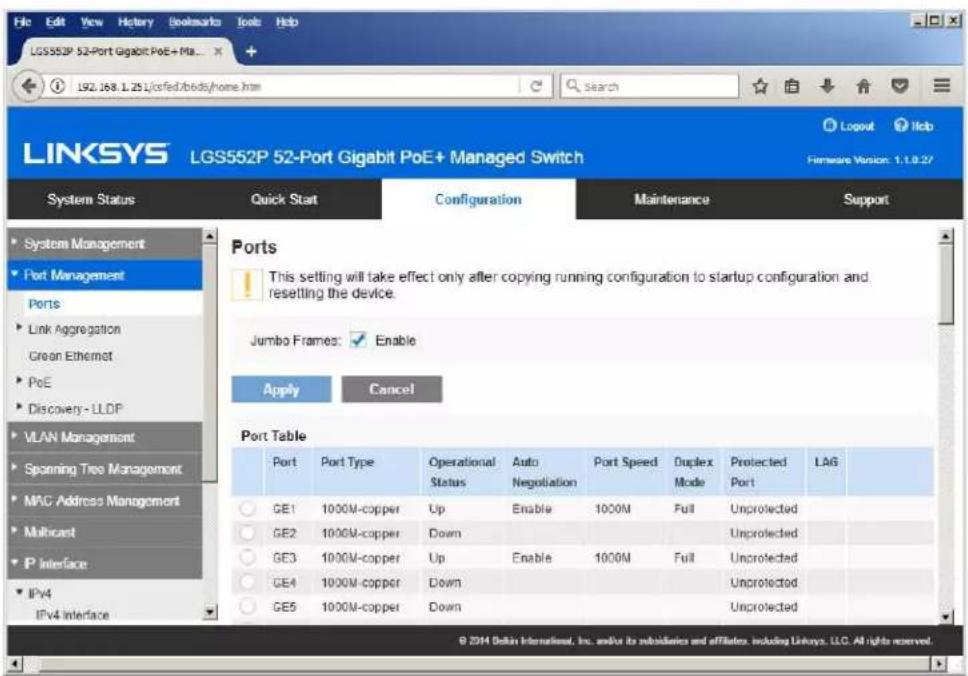
- Navigate to Port Management -> Ports. Select Enable under Jumbo Frames and click Apply.
- Navigate to Multicast -> Future Configuration. Select Enable under Bridge Multicasting Filtering and click Apply.

- Navigate to Multicast -> IGMP Snooping. Select Enable under IGMP Snooping, click Apply.
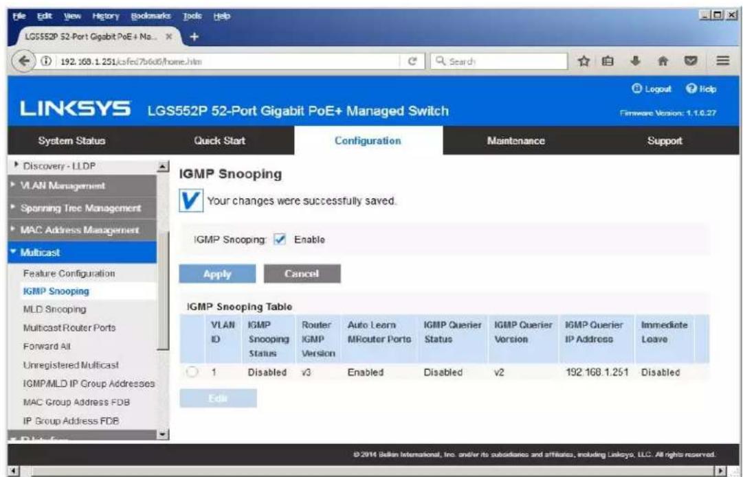
- Click on radio button and click Edit. Edit IGMP Snooping window will appear. Make sure VLAN ID <1> is selected. Enable all the settings as shown below. Select IGMP v2 as IGMP Querier Version, Click Apply and then Close.
- Refresh your browser, go to IGMP Snooping tab and make sure you have an image as below:

- Navigate to Maintenance -> File Management -> Configuration File Copy. Select radio buttons as shown below, click Apply. This will save current configuration and will apply this configuration every time switch is powered up.

- Power down Linksys network switch and power it up back again.
- Log in to your Linksys network switch again and make sure that IGMP settings are intact:

- At this point your Linksys network switch is set and ready to use.
- Connect your encoders, decoders, allow approx 3 mins for bootup, and perform a network scan using KD Management Software.
Luxul AMS-4424P, SW-610-24P-R, SW-510-48P-F
Network Setup Guide for KD-IP822, KD-IP922, KD-IP1022, KD-IP1080
Important Notes:
- When stacking – verify that both switches have POE enabled. In some cases, the secondary switch may disable POE upon stacking.
1. Login to the switch:
a. Plug an Ethernet cable into any of the ports of the switch
b. Plug the other end into the Ethernet port of your computer
c. Power on the Switch
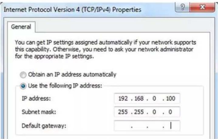
d. Check to see that the IP address of the computer is within this network Subnet : 192.168.0.xxx ("xxx" ranges 1\~254). For example, 192.168.0.100

- Open the Web browser, and enter 192.168.0.4 (default IP address of Luxul AMS-4424P). The login window appears as below:

- Enter the user name and password. (default user name and password are both set as "admin"), then click "OK" to login to the switch configuration window.
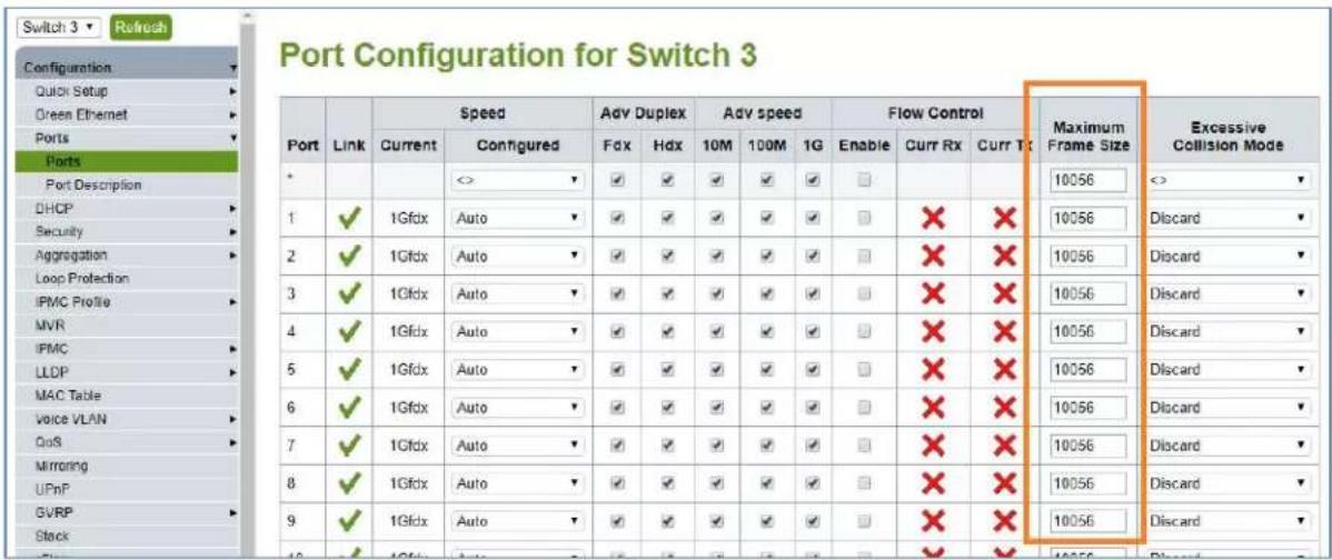
- Ensure all ports have Maximum Frame Size of 10056 entered as below. To check it, find Configuration → Ports → Ports in the menu on left side of the window. (KD-IP922 requires Jumbo Frame(8K) for video/audio transmission via 1G-BaseT).
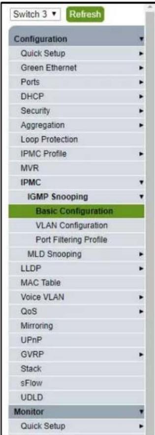
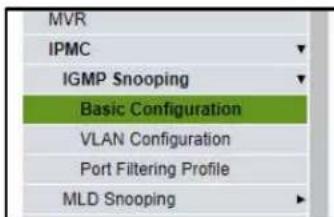
- To enable IGMP Snooping of the switch, Find Configuration → IPMC → IGMP Snooping → Basic Configuration in the menu on left side of the window. (KD-IP922 requires IGMP Snooping for multicasting video/audio transmission via 1G-BaseT), then check the box of Snooping Enabled of Global Configuration in
IGMP Snooping Configuration window. And check the Fast Leave box for all Ports related Configuration in the same window as below.
IGMP Snooping Configuration
Stack Global Settings
| Global Configuration | Enabled | ||
| Snooping Enabled | ☑ | ||
| Unregistered IPMCv4 Flooding Enabled | ☐ | Make sure unchecked. | |
| IGMP SSM Range | 232.0.0.0 | / 8 | |
| Leave Proxy Enabled | ☐ | ||
| Proxy Enabled | ☐ | ||
Port Related Configuration for Switch 3
| Port | Router Port | Fast Leave | Throttling |
| * | |||
| 1 | unlimited | ||
| 2 | unlimited | ||
| 3 | unlimited | ||
| 4 | unlimited | ||
| 5 | unlimited | ||
| 6 | unlimited |
- Click "Save" button on the bottom of IGMP Snooping Configuration window
| 22 | unlimited | ||
| 23 | unlimited | ||
| 24 | unlimited |

- To add VLAN of the IGMP Snooping at the switch, Find Configuration → IPMC → IGMP Snooping → VLAN Configuration in the menu on left side of the window. (VLAN must be added in IGMP Snooping), then click "Add New IGMP VLAN" if there is not any specified VLAN in IGMP Snooping VLAN Configuration window.
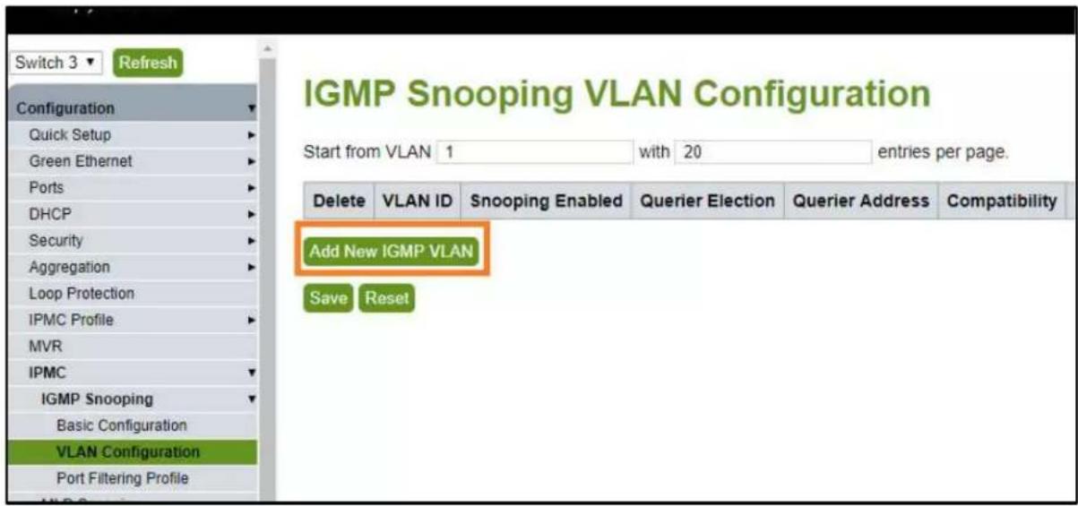
- Then enter "1" in VLAN ID, check the box of Snooping Enabled and Querier Election in new VLAN. And select "Forced IGMPv2 in the list box of Compatibility in IGMP Snooping VLAN Configuration window. Then click "Save" button on the bottom of IGMP Snooping VLAN Configuration window.

- (optional). If using stacked Switches, verify that POE+ is enabled. This setting can be accessed from Configuration→ Quick Setup → POE→ Configuration
| Configuration | |
| Quick Setup | |
| System | |
| PoE | |
| Configuration | |
| Scheduling | |
| Auto Check | |
| VLANs | |
| Private VLANs | |
| VCL | |
| Spanning Tree | |
| Green Ethernet | |
| Ports | |
| DHCP | |
| Security | |
| Aggregation |
Power Over Ethernet Configuration
| Reserved Power determined by | Class | Allocation | LLDP-MED |
| Power Management Mode | Actual Consumption | Reserved Power | |
| Capacitor Detection | Disabled | Enabled |
Maximum Available PoE Power is 250W
PoE Port Configuration for Switch 1
| Port | PoE Mode | Priority | Maximum Power [W] |
| * | <> | <> | 15.4 |
| 1 | PoE+ | Low | 15.4 |
| 2 | PoE+ | Low | 15.4 |
- (optional) if aggregating 10G connections, navigate to Configuration→Aggregation → Groups Use static mode for aggregated 10G connections.
| Configuration | |
| ▼ | |
| Quick Setup | ▼ |
| System | ▼ |
| PoC | ▼ |
| VLANe | ▼ |
| Spanning Tree | ▼ |
| Group Manager | ▼ |
| Green Ethernet | ▼ |
| Thermal Protection | ▼ |
| Ports | ▼ |
| DHCPv4 | ▼ |
| DHCPv5 | ▼ |
| Security | ▼ |
| Aggregation | ▼ |
| Commute | ▼ |
| Groups | ▼ |
| LACP | ▼ |
Aggregation Group Configuration
| Port Members | Group Configuration | |||||||||||||||||||||||||||||||
| Group ID | 1 | 2 | 3 | 4 | 5 | 6 | 7 | 8 | 9 | 10 | 11 | 12 | 13 | 14 | 15 | 16 | 17 | 18 | 19 | 20 | 21 | 22 | 23 | 24 | 25 | 26 | 27 | 28 | Mode | Revertive | Max Bundle | |
| Normal | ||||||||||||||||||||||||||||||||
| 1 | Static | 28 | ||||||||||||||||||||||||||||||
| 2 | Disabled | 28 | ||||||||||||||||||||||||||||||
| 3 | Disabled | 28 | ||||||||||||||||||||||||||||||
| 4 | Disabled | 28 | ||||||||||||||||||||||||||||||
| 5 | Disabled | 28 | ||||||||||||||||||||||||||||||
| 6 | Disabled | 28 | ||||||||||||||||||||||||||||||
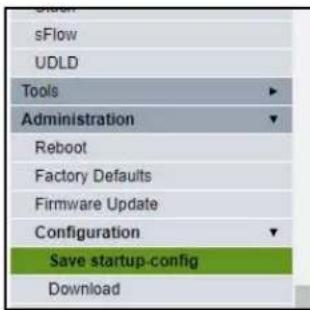
- To save all Running Configurations to Startup-Configuration, Find Administration → Configuration → Save startup-config in the menu on left side of the window. Then click "Save Configuration" button in Save Running Configuration to startup-config window.
Save Running Configuration to startup-config
Please note: The generation of the configuration file may be time consuming, depending on the amount

- To reboot the switch, Find Administration → Reboot in the menu on left side of the window. Then click "Yes" button in Reboot Device window. The switch will be rebooted automatically.

Netgear AV line: MS250-10G2XF-POE+, M4250-26G4XF-PoE+, M4250-40G8XF-PoE+
This series is compatible with IP1080, IP822, IP922, and IP1022 with no additional configuration required. However, it is recommended to change the default profile to the "video" profile (default is "data") type for enhanced system performance.
If not connected to a DHCP server, the switch can be accessed via its IP address: 169.254.100.100
Alternatively, the OOB port can be accessed via 192.168.0.239
NETWORK TO HIPS
Configure | Network Profiles
M4250-40G8XF-PoE+
Snow Leg
Auto-Trunk

PTP residency time stamping

Configured Profiles
Profile Name
Profile type
VLAN ID
IP Address
# of Assigned Ports
Derfautit
Video
1
192.168.1.251
48

Configured Profiles
| Profile Name | Profile type | VLAN ID | IP Address | # of Assigned Ports |
| ■ Default | Video | 1 | 192.168.1.251 | 48 |
Profile Settings
Configure your profile settings and preferences.
Profile Name
Default
VLAN ID
1
Profile Template
Video
Color

000000
Edit VLAN Routing / DHCP Server
VLAN IP Settings
Static

Subnet Mask
255.255.0.0
DHCP Server
Off

Cancel
VLAN IP Address
192.168.1.251
Apply
For ease of maintenance, it is recommended to adjust the management IP address of the switch to a static IP address that shares the same subnet as the system.
Device Details
Product Name
M4250
Serial Number
6VK2295AA036A
Country/Region
N/A
Base MAC Address
94:18:65:6F:86:1C
AV UI Version
1.0.8.17
Boot Version
1.0.0.7
Management IP Address
192.168.1.251

STP Network Redundancy
Neutral mode (default)

Netgear GS Series
Network Setup Guide for KD-IP822, KD-IP922, KD-IP1022, KD-IP1080
Login to the switch with the following steps:
- Plug an Ethernet cable into any of the ports of the switch
-
Plug the other end into the Ethernet port of your computer
-
Power on the Switch
-
Check to see that the IP address of the computer is within this network, 192.168.0.xxx ("xxx" ranges 1\~254). For example, 192.168.0.100
- Open the Web browser, and enter 192.168.0.239 (default IP address of Netgear GS). The login window appears as below:
- Enter the password (default password is "password"). And then click 'OK' to login to the switch configuration window
- To enable Jumbo Frame of the switch, go to Switching -> Ports -> Port Configuration. (IP922 requires Jumbo Frame(8K) for video/audio transmission via 1G-BaseT). Select the empty checkbox that is above the checkbox beside g1 Port in the table to select all the ports. All selected ports highlight to yellow color. Then enter "9216" in Maximum Frame Size field as shown below and press Apply button
| Port Configuration | |||||||||||||||
| 1 LAG Ad | On | ||||||||||||||
| Port | Disruption | Port Type | Admin Mode | Autismegmentation | Speed | Duplex Mode | Physical Status | Link Status | Link Trap | Fzome Spn. (1622 to 180.0) | Flow Control | MAC Content | Print, Let the Offload | Window | |
| g1 | Enable | Enable | Auto | Auto | 1000 Mbps Full Duplex | Link Up | Enable | 9999 | Disable | 94:18:65:39:14:52 | 1 | 1 | |||
| g2 | Enable | Enable | Auto | Auto | Link Down | Enable | 9999 | Disable | 94:18:65:39:14:52 | 2 | 2 | ||||
| g3 | Enable | Enable | Auto | Auto | Link Down | Enable | 9999 | Disable | 94:18:65:39:14:52 | 3 | 3 | ||||
| g4 | Enable | Enable | Auto | Auto | 1000 Mbps Full Duplex | Link Up | Enable | 9999 | Disable | 94:18:65:39:14:52 | 4 | 4 | |||
| g5 | Enable | Enable | Auto | Auto | Link Down | Enable | 9999 | Disable | 94:18:65:39:14:52 | 5 | 5 | ||||
| g6 | Enable | Enable | Auto | Auto | Link Down | Enable | 9999 | Disable | 94:18:65:39:14:52 | 6 | 6 | ||||
| g7 | Enable | Enable | Auto | Auto | Link Down | Enable | 9999 | Disable | 94:18:65:39:14:52 | 7 | 7 | ||||
| g8 | Enable | Enable | Auto | Auto | Link Down | Enable | 9999 | Disable | 94:18:65:39:14:52 | 8 | 8 | ||||
| g9 | Enable | Enable | Auto | Auto | 100 Mbps Full Duplex | Link Up | Enable | 9999 | Disable | 94:18:65:39:14:52 | 9 | 9 | |||
| g10 | Enable | Enable | Auto | Auto | 100 Mbps Full Duplex | Link Up | Enable | 9999 | Disable | 94:18:65:39:14:52 | 10 | 10 | |||
| g11 | Enable | Enable | Auto | Auto | Link Down | Enable | 9999 | Disable | 94:18:65:39:14:52 | 11 | 11 | ||||
| g12 | Enable | Enable | Auto | Auto | Link Down | Enable | 9999 | Disable | 94:18:65:39:14:52 | 12 | 12 | ||||
| g13 | Enable | Enable | Auto | Auto | 1000 Mbps Full Duplex. 1000 Mbps Full Duplex. 1000 Mbps Full Duplex. 1000 Mbps Full Duplex. 1000 Mbps Full Duplex. 1000 Mbps Full Duplex. 1000 Mbps Full Duplex. 1000 Mbps Full Duplex. 1000 Mbps Full Duplex. 1000 Mbps Full Duplex. 1000 Mbps Full Duplex. Link Up Enable 9999 Disable 94:18:65:39:14:52 14 14 15 16 17 18 18 18 18 18 18 18 18 18 18 18 18 18 18 18 18 18 18 18 18 18 18 18 18 18 18 18 18 18 18 18 18 18 18. 20 20 20 20 20 20 20 20 20 20 20 20 20 20 20 20 20 20 20 20 20 20 20 20 20 20 20 20 20 20 20 20 20 20.23.23.23.23.23.23.23.23.23.23.23.23.23.23.23.23.23.23.23.23.23.23.23.23.23.23.23.23.23.23.23.23.23.23 .23 .23 .23 .23 .23 .23 .23 .23 .23 .23 .23 .23 .23 .23 .23 .23 .23 .23 .23 .23 .23 .23 .23 .23 .23 .23 .23 .23 .23 .23 .23 .23 .23 . | ||||||||||
- To enable IGMP Snooping of the switch, go to Switching -> Multicast -> IGMP Snooping -> IGMP Snooping Configuration. (IP922 requires IGMP Snooping for multicasting video/audio transmission via 1G-BaseT), Enable IGMP settings as shown below and press Apply button
NETGEAR
NETGEAR 48-Port Gigabit PoE+ Smart Managed Pro Switch with 4 SFP Ports (GS752TPv2)
| System | Switching | Routing | QoS | Security | Monitoring | Maintenance | Help | Index | ||||
| Ports | LAG | VLAN | Auto-VoIP | STP | Multicast | MVR | Address Table | L2 Loop Protection | ||||
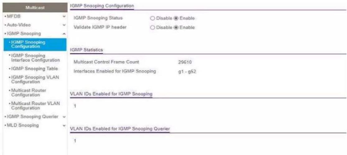
- Go to Switching -> Multicast -> IGMP Snooping -> IGMP Snooping Interface Configuration. Select the empty checkbox that is above the checkbox beside g1 Port in the table to select all the ports. All selected ports highlight to yellow color. Enable Admin Mode and Fast Leave Admin Mode as shown below and press Apply button

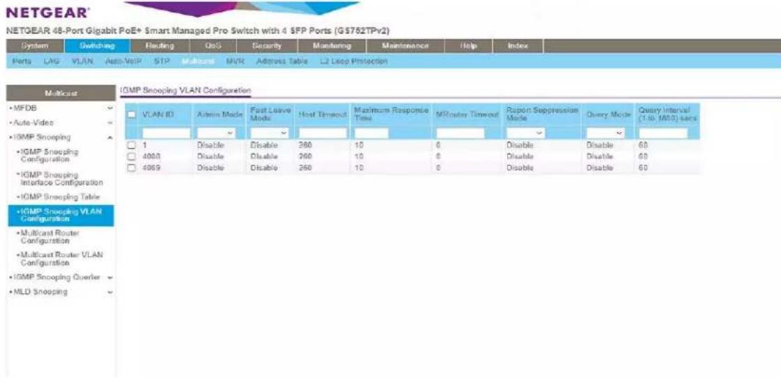
- Go to Switching -> Multicast -> IGMP Snooping -> IGMP Snooping VLAN Configuration. Add VLAN ID=1, Fast Leave Admin Mode=Enable and Query Mode=Enable as shown below and press Add button. (Note: the empty fields are populated automatically to default values)
- Go to Switching -> Multicast > IGMP Snooping Querier -> Querier Configuration. Enable Querier Admin Mode as shown below and press Apply button
NETGEAR®
NETGEAR 48-Port Gigabit PoE+ Smart Managed Pro Switch with 4 SFP Ports (GS752TPv2)
| System | Switching | Routing | QoS | Security | Monitoring | Maintenance | Help | Index | ||||
| Ports | LAG | VLAN | Auto-VoIP | STP | Multicast | MVR | Address Table | L2 Loop Protection | ||||

- Finally, go to Maintenance -> Device Reboot. Enable checkbox for device reboot as shown below and press Apply button. It takes approximately 2 minutes to power cycle the switch and an additional 2 min for IP922 to start showing video.
NETGEAR
NETGEAR 48-Port Gigabit PoE+ Smart Managed Pro Switch with 4 SFP Ports (GS752TPv2)
| System | Switching | Routing | QoS | Security | Monitoring | Maintenance | Help | Index | ||
| Reset | Export | Update | File Management | Troubleshooting | ||||||
| Reset | Device Reboot |
| • Device Reboot | Select this check box and click the Apply button to reboot. |
| • Default Settings |
Niveo NGSME24TH-AV
Network Setup Guide for KD-IP822, KD-IP922, KD-IP1022, KD-IP1080
- Set up the computer to connect to the switch. The best method is to set a static IP address for the computer's ethernet adapter and directly wire into the switch. The Default IP address of this switch is 192.168.2.1
- Once wired in, connect to the network switch via web browser. When prompted, log in with the default credentials.
a. The username and password are both "admin".
- After connecting to the switch, it is recommended to reset it to factory defaults.
a. The path for this is Maintenance -> Factory Defaults.
b. Note that resetting the switch to Factory Defaults does not change the IP settings of the switch.

- After setting factory defaults, adjust the switch to use the desired subnet. In our case we use the IP address 192.168.1.251 – as this fits the default subnet of the KD-IP922 system. Ensure the DHCP client is disabled as well. Set the Router IR address to that of the router in the network.
a. The path is: Configuration -> System -> IP
b. After making the adjustment, the switch will automatically move to the new IP address. The computer may lose connection to the switch at this time. Adjusting the static IP to be in the new subnet will allow for connection to be reestablished on the new IP address.
IP Configuration
| Configured | Current | |
| DHCP Client | ☐ | Renew |
| IP Address | 192.168.1.251 | 192.168.2.1 |
| IP Mask | 255.255.255.0 | 255.255.255.0 |
| IP Router | 192.168.1.1 | 0.0.0.0 |
| VLAN ID | 1 | 1 |
| DNS Server | 0.0.0.0 | 0.0.0.0 |
IP DNS Proxy Configuration

- By default, Jumbo frames are enabled on this network switch. Verify that the maximum frame size is 9600 (the maximum value)
a. The path is: Configuration -> Ports
Port Configuration
| Port | Link | Speed | Flow Control | Maximum Frame Size | Excessive Collision Mode | Power Control | ||||
| Current | Configured | Current Rx | Current Tx | Configured | ||||||
| <>▼ | 9600 | <>▼ | <>▼ | |||||||
| 1 |  | Auto | ✓ | ✘ | ✘ | 9600 | Discard | Disabled | ✓ | |
| 2 |  | Auto | ✓ | ✘ | ✘ | 9600 | Discard | Disabled | ✓ | |
| 3 |  | Auto | ✓ | ✘ | ✘ | 9600 | Discard | Disabled | ✓ | |
| 4 |  | Auto | ✓ | ✘ | ✘ | 9600 | Discard | Disabled | ✓ | |
| 5 |  | Auto | ✓ | ✘ | ✘ | 9600 | Discard | Disabled | ✓ | |
- Enable IGMP Snooping. Check "Snooping Enabled" and verify that "Fast Leave" is also enabled. Uncheck "Unregister IPMCv4 Flooding enabled"
a. The path is: Configuration -> IPMC -> IGMP -> Basic Configuration

- Create an IGMP VLAN. The ID should be set to 1. Force IGMPV2 compatibility for this VLAN. Ensure the configuration is as below:
a. The path is: Configuration -> IPMC -> IGMP -> VLAN Configuration
- Reboot the network switch and verify that the settings are correct. The switch is now ready for the KD-IP922 system.
a. There is no need to save the running configuration of this network switch. The settings will persist on system reboot.
Pakedge S3L
Network Setup Guide for KD-IP822, KD-IP922, KD-IP1022, KD-IP1080
Login to the switch with the following steps:
- Plug an Ethernet cable into any of the ports of the switch
- Plug the other end into the Ethernet port of your computer
-
Power on the Switch
-
Check to see that the IP address of the computer is within this network, 192.168.1.xxx ("xxx" ranges 1\~254). For example, 192.168.1.154
- Open the Web browser, and enter 192.168.1.205 (default IP address of Pakedge S3L). Then the login window appears as below.
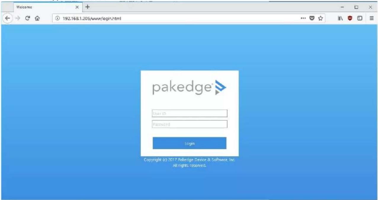
- Enter the User ID (default user id is "pakedge") and password (default password is "pakedges"). And then click 'OK' to login to the switch configuration window. Make sure to set appropriate IP address and netmask to make the switch to be in same network as the Key Digital Devices you are going to be using.
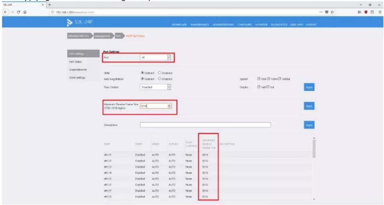
- To enable Jumbo Frame of the switch, go to Administration -> Management -> Port. (IP922 requires Jumbo Frame(8K) for video/audio transmission via 1G-BaseT). Make sure under Port Settings, Port field is set to All. Then enter "9216" in Maximum Receive Frame Size field as shown below and press Apply button. After applying check that the settings are updated in the table below.
- To enable IGMP Snooping of the switch, go to Configure -> Application -> IGMP Snooping. (IP922 requires IGMP Snooping for multicasting video/audio transmission via 1G-BaseT), Enable IGMP settings as shown below and press Apply button. You should see a new entry in the table below.

- Go to Configure -> Application -> IGMP. Enter the settings as shown in the picture below and press Apply button. You should see the updated settings in the entries table below.


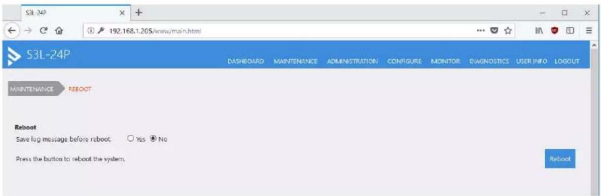
- Go to Maintenance -> Save. Click on Save button.
- Go to Maintenance -> Reboot. Click on Reboot button. It takes approximately 30 seconds for the switch to reboot and an additional 30 sec for IP922 to start showing video.
Pakedge SX Series
IGMP Setup Guide for KD-IP822, KD-IP922, KD-IP1022, KD-IP1080
1. Connect to the network switch
a. Plug an Ethernet cable into any of the ports of the switch
b. Plug the other end into the Ethernet port of your computer
c. Power on the Switch
d. Configure the PC with static IP address of 192.168.1.10 and the subnet mask of 255.255.255.0 to be within range of Pakedge's default settings (IP address 192.168.1.205 subnet mask 255.255.255.0). Default Getaway and DNS can be left blank

-
Open a web browser, and enter 192.168.1.205 (default IP address of Pakedge) to enter the login window
-
Enter the user name and password (default user name is pakedge and password is pakedges) and then click Login to login to the switch configuration window.
- Go to System Settings and change the Subnet Mask to 255.255.0.0. Press the apply button.

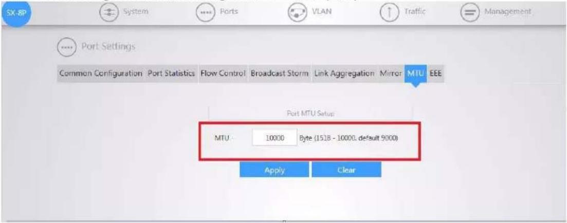
- Go to Port → Port Settings → MTU and change MTY to 10,000 (max)
-
Go to TRAFIC→ IGMP → IGMP Snooping and Enable IGMP Status, and Report Suppression. Press the Apply button.
-
Press the button with red pencil icon

- Enable State and Immediate Leave

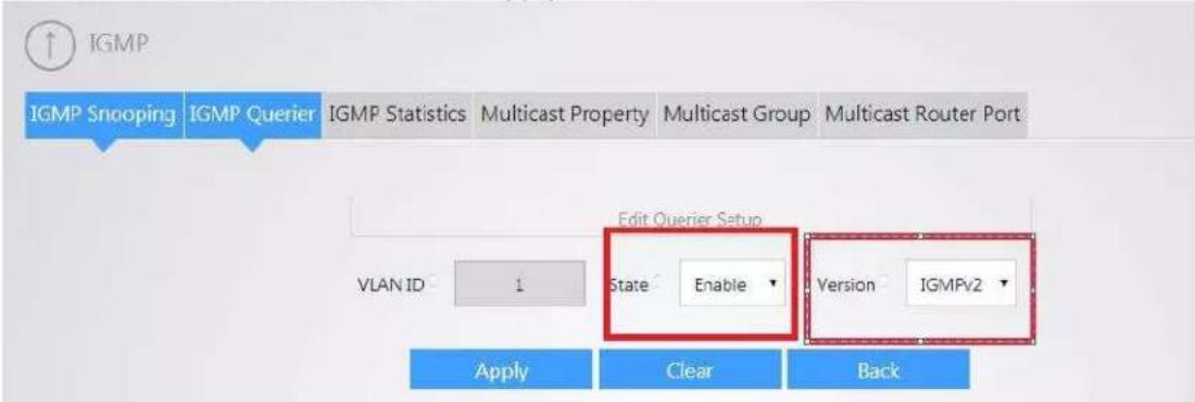
- Go to TRAFIC → IPMC → IGMP Querier and press the button with red pencil icon

- Enable State and choose IGMPv2 version. Click Apply button
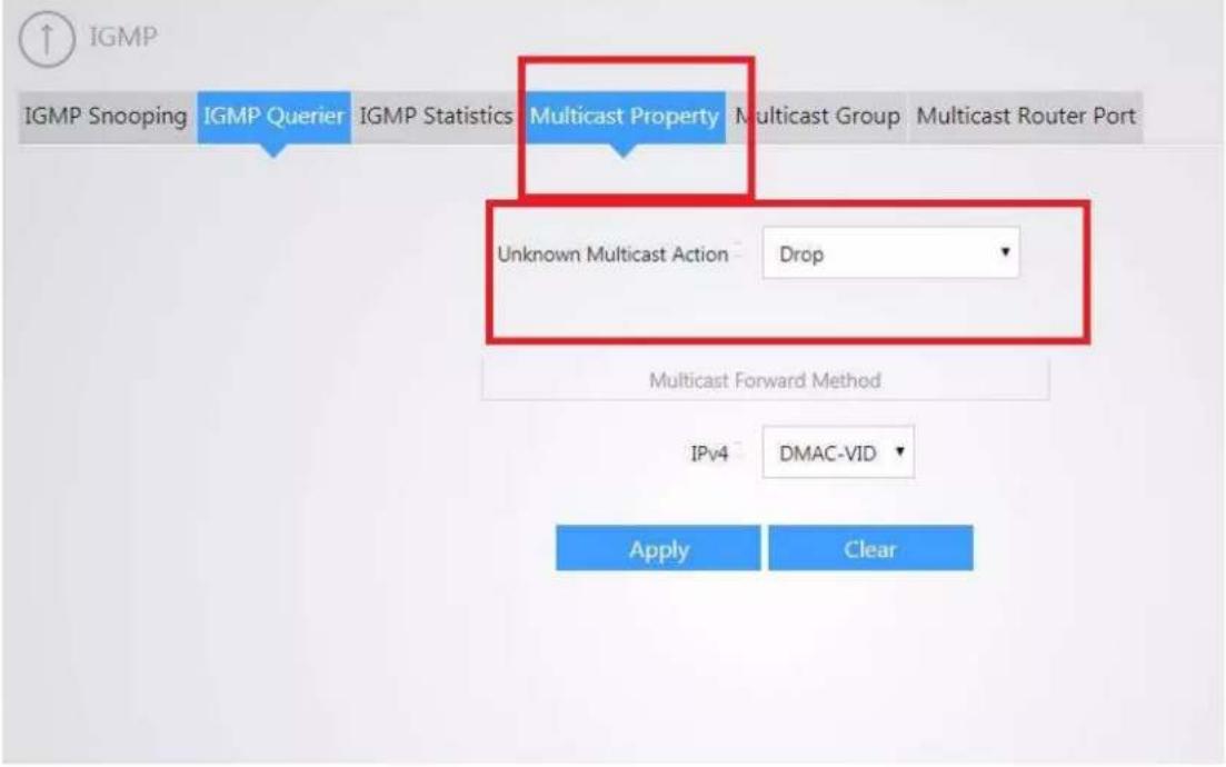
- Go to TRAFIC→IPMC→MULTICAST PORPERTY and set Unknown Multicast Action to Drop. Press Apply
Signamax SC30020
Network Setup Guide for KD-IP822, KD-IP922, KD-IP1022, KD-IP1080
- Connect your PC directly to the network switch. Your PC will need to be set to a static IP address that is within the subnet of the default IP address of the switch. This series of switches typically use 192.168.2.1 as their default IP address

- Log into the switch via web browser using the IP address. There will be a prompt to enter credentials. By default, both username and password are set to "admin"
- Navigate to System -> Capability, and enable Jumbo Frames as depicted in the below image

- Navigate to Multicast -> IGMP Snooping -> General to access basic IGMP settings. On this page, enable IGMP snooping and Querier, as depicted in the below image.

- Navigate to Multicast -> IGMP Snooping -> Interface. From this page, use the dropdown to select "Configure VLAN". Set VLAN 1 up as depicted below.

Action: Configure VLAN
VLAN
IGMP Snooping Status
Version Exclusive
Immediate Leave Status
Multicast Router Discovery
General Query Suppression
Proxy Reporting
Interface Version
Query Interval (2-31744)
Query Response Interval (10-31740)
Last Member Query Interval (1-31744)
Last Member Query Count (1-255)
Proxy (Query) Address
1
Enabled
Using Global Status
Enabled
Enabled
Enabled
Using Global Status
Using Global Version
125
100
10
2
0.0.0.0
Apply
Revert
- Navigate to IP -> General -> Routing Interface. From this page, use the dropdown to select "Add address". Add a new static, primary IP address for VLAN 1 from this screen. For best performance, use an IP in the same subnet as your system.

- To save all settings, click on the floppy disk button on the top right corner of the control panel, then reboot. After rebooting, the switch will be ready to manage an IP system

line
| Metric | Value | | --- | --- | | CPU Utilization (%) | 100% | | Switch Events | 6 (Informational) / 6 (100%) | | Memory Utilization | 0% - 50% | | Switch Information | Switch Model: SC30020 | | Switch Information | Up Time: 0 days, 0 hours, 14 minutes, and 17.54 seconds | | Switch Information | Serial Number EC2002000069 | | Switch Information | Hardware Version R01 | | Switch Information | Loader Version 0.2.1.1 | | Switch Information | Firmware Version 1.2.2.24 | | Memory Utilization | Free Size | | Memory Utilization | Used Size |IGMP Setup Guide: Titan Network 1080p Systems (KD-IP1080, KD-IP120)
- IMPORTANT: Disconnect all the DHCP devices like routers, servers from the Linksys network switch.
- Locate a pinhole "RESET" button at the front panel left bottom corner of your Titan Network switch. Using a paper clip press and hold a reset button for more than 10 seconds and then release. Wait while the device is restarted and ready to use (about 5min).
- IMPORTANT: At this point all the displays should be displaying distorted randomly flashing video images.
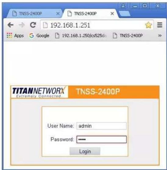
- Connect your PC to the Titan Networkx network switch directly using a network cable.
- If you have not done yet, configure your PC's IP address to the same range as the switch (default 192.168.1.xxx).
- Enter the switch's IP address in your browser and press ENTER (check the user manual for a default IP address – usually, it is: 192.168.1.30).
- Enter user name and password (check the user manual for a default user name and password; it is usually "admin" for both). Then click Log In.
-
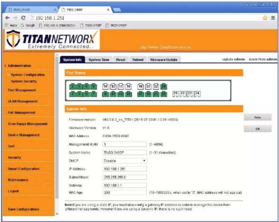
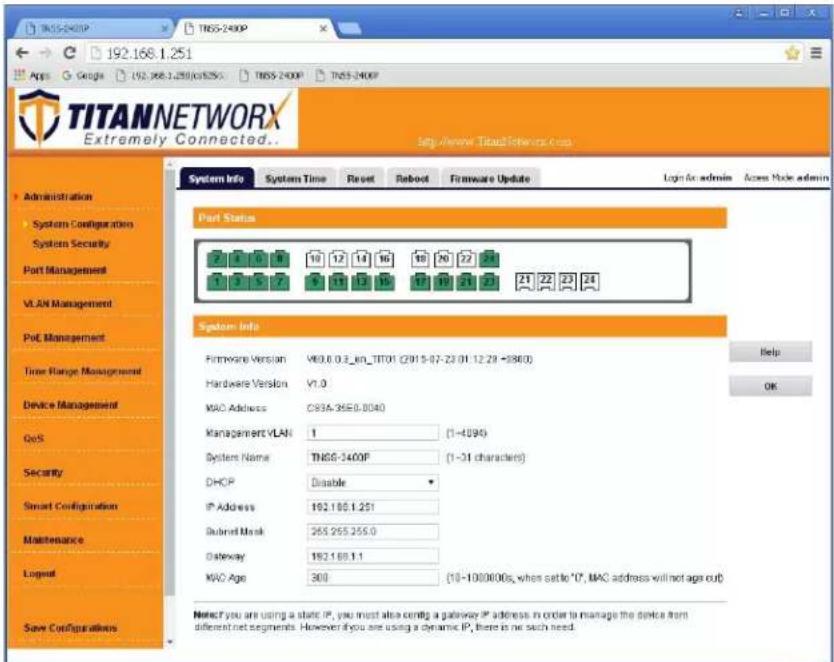
Navigate to Administration -> System Configuration. Select IP Address box. IP address can be changed by the administrator depending on the network configuration. If you are using multiple network switches it is recommended to set first one to 192.168.1.251, second to 192.168.1.252, and so on (we will change an IP address to 192.168.1.251). Set Subnet Mask to 255.255.255.0, set Gateway to 192.168.1.1 (in this case), make sure that Management VLAN is set to "1", DHCP is set to "Disable" and click OK. Page will refresh with the new IP address. If it is timed out than log in again using the new IP address.
-
Make sure your screen looks exactly like pictured below.
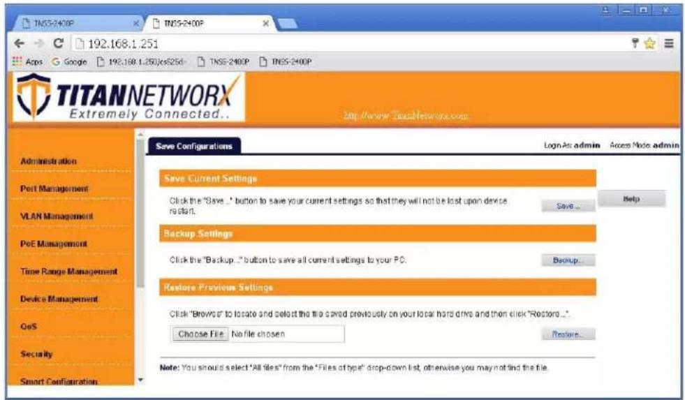
- Click Save Configurations on the left bottom corner. New screen will appear. Click Save under Save Current Settings, then OK and OK again.

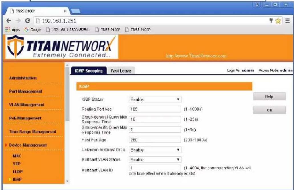
- Navigate to Device Management-> IGSP, Select IGMP Snooping tab. Set IGSP Status to Enable, set Unknown Multicast Drop to Enable, set Multicast VLAN Status to Enable, set Multicast VLAN ID to "1", and leave all other settings as indicated below. Click OK, and OK again.

12. Select Fast Leave tab. Click Config button.
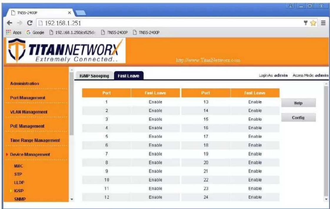
13. Set Fast Leave to Enable, click Select All. Click OK, and OK again.
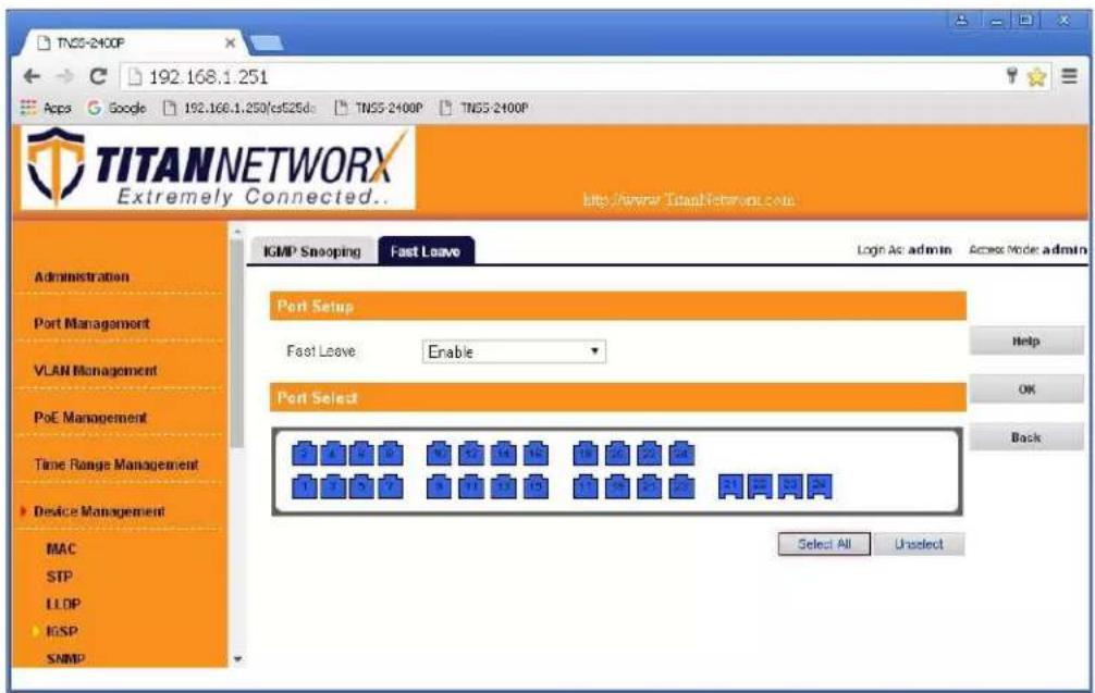
- Make sure all the ports are set to Enable.

- Click Save Configurations on the left bottom corner. New screen will appear. Click Save under Save Current Settings, than OK and OK again.
- Power down Titan Network network switch and power it up back again. Wait for the switch to reboot.
- Log in to your Titan Network network switch again and make sure that IGMP settings are intact:
- At this point your Titan Networkx network switch is set and ready to use.
- Connect your encoders, decoders, allow approx 3 mins for bootup, and perform a network scan using KD Management Software.
IGMP Setup Guide: TP-Link TL-SG2428P (Single use only available, not stackable)
TP-Link TL-SG3210XHP-M2 (stackable)
TP-Link TL-SG3428XMP (stackable)
4K Systems (KD-IP822, KD-IP922, KD-IP1022)
\*Steps related to stacking multiple switches are in red\*
- Power-up the TP-Link network switch.
- IMPORTANT: Disconnect all the DHCP devices like routers or servers from the TP-Link network switch.
- (If you want factory reset of the switch) Locate a pinhole "RESET" button at the front center panel of your TP-Link network switch. Using a paper clip press and hold a reset button for more than 5 seconds and then release. The factory reset process generally takes 5 minutes to complete
- Connect your PC to the TP-Link network switch directly using a network cable.
- If you have not done yet, configure your PC's IP address to the same range as the switch. (default subnet of the switch - 192.168.0.xxx).
- Enter the switch's IP address in your browser and press ENTER (default IP address - 192.168.0.1).
- Enter username and password (default "admin" for both). Then click Log In. If this is the first time logging in, there will be a prompt to create a new password.
8. Set the static IP address of the network switch.
Go to L3 FEATURES -> Interface. Ensure IPv4 Routing is enabled. If not, apply the IPv4 routing. Click "Edit IPv4" to set the desired IP address of the network switch.

9. Select "Static" and enter the desired IP address and subnet mask. Click Apply.
IP address can be changed by the administrator depending on the network configuration.
We recommend using an address that is within the subnet of the AVoIP system for ease of maintenance. After applying, you will need to log in again using new IP address. (Ensure the PC and switch are the same
network before login).

10. Confirm the updated IP address table.
Go to L3 FEATURES -> IPv4 Routing Table.

11. Enable Jumbo Frames.
Go to L2 Features -> Port and set frame size to 9216
12. IGMP setup.
Go to L2 FEATURES -> Multicast -> MLD Snooping. Select "Enable" under MLD Snooping. Click Apply.
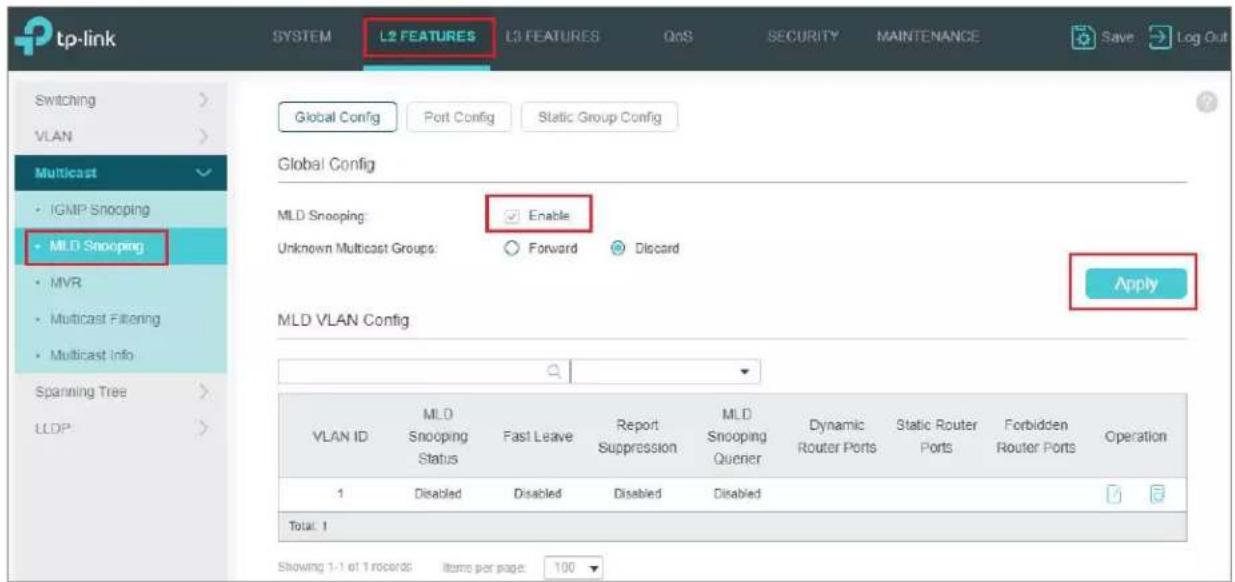
13. Go to L2 FEATURES -> Multicast -> IGMP Snooping -> Global Config.
Select Enable under IGMP Snooping. Select v2 version and Discard for Unknown Multicast Groups. And click Apply.
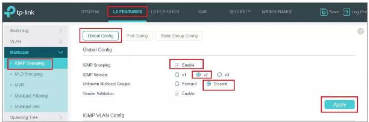
- After applying the settings from the step 13, click the icon under IGMP VLAN Config table.
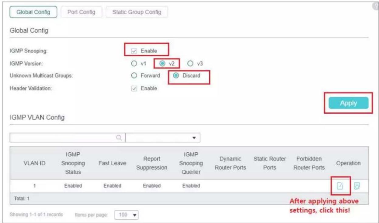
- IGMP Snooping window will appear. Make sure below settings (red boxes) enabled.
Change "General Query Source IP" to the current network switch's IP address. (192.168.1.251 in this case).
a. Have all switches share the same general query source IP

- Scroll down the window and leave all the ports unchecked. Click Save.
a. In some cases, the specific port connected to any Wi-Fi routers or a core network may need to be forbidden at this page. If applicable, check those ports ONLY and leave others unchecked

- Enable Fast Leave on all ports.
Go to L2 FEATURES -> Multicast -> IGMP Snooping -> Port Config.

18. View IGMP VLAN Configurations.
Go to L2 FEATURES -> Multicast -> IGMP Snooping -> Global Config. Click icon (yellow box in image).

19. Save the current configuration.
Click "Save" button on top right corner. Click Yes.
This will save current configuration and will apply this configuration every time switch is powered up.
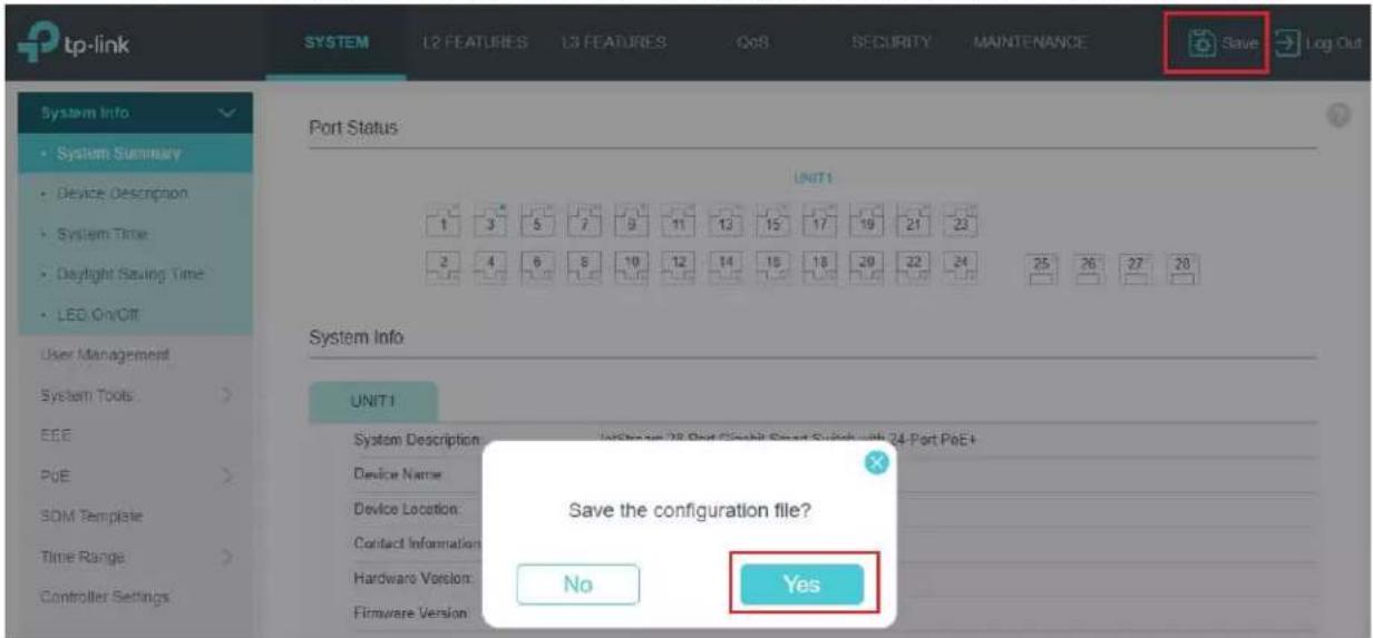
- If aggregating 10G fiber connections, navigate to L2 Features -> LAG -> Static LAG. Assign all relevant ports to the LAG and confirm. Use the LAG table to confirm the proper settings have been applied.
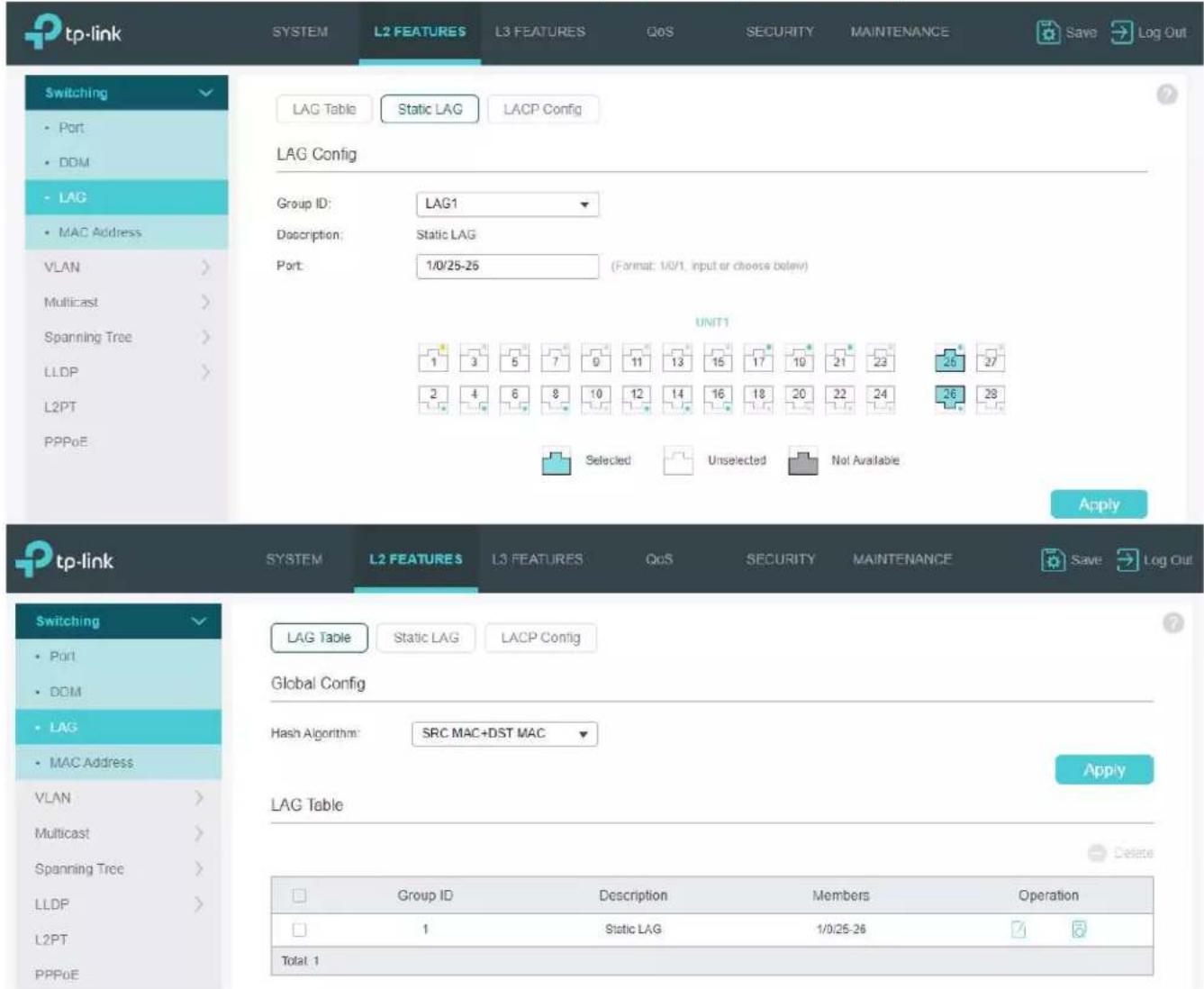
- To double-check the updated configuration, reboot the network switch and confirm the configuration. After rebooting the switch, log in to your TP-Link network switch again and make sure that IGMP settings are intact.
- Connect your encoders, decoders, allow approx 3 mins for bootup, and perform a network scan using KD Management Software.
WiFi Router Setup
It is required to set your WiFi router to filter multicast (aka filter broadcast) to ensure that your router is not overwhelmed by the data broadcast from AV over IPunits on the network.
Example of applying multicast filtering in a Linksys router:

*The following requirements must be met in order to support the live streaming feature of the Key Digital app (1080p systems, KD-IP1080/KD-IP120 only):
■ Verified model = Cisco/Linksys EA6700 router
• Network switch must support IGMP v3 and configured to enable IGMP v3.
■ Wifi Router
- Must be configured so that multicast filtering is enabled. See above example
- Must support 50Mbps bandwidth per iOS that will be streaming video
It is recommended that only 1 iOS be in the Live Stream page at a time
iOS Device
- Best performance is with iPad4, iPad Air, iPad Mini. More powerful processing will always benefit.
- Should have Static IP with Router IP corresponding to master network switch

- Verified Network Switch Guide
- For use with Key Digital AV over IP Systems
- IMPORTANT: Configure your network switch according to this guide BEFORE connecting your AV over IP units.
- Introduction
- Key Digital AV over IP Supported Models:
- System Facts
- 4K Systems: KD-IP822, KD-IP922, KD-IP1022 models
- 1080p Systems: KD-IP1080, KD-IP120 models
- Network switch Requirements for KD AV over IP
- IGMP Setup Guide: Araknis 1080p Systems (KD-IP1080, KD-IP120)
- IGMP Setup Guide: Araknis 4K Systems (KD-IP822/922/1022)
- Cisco Meraki series
- Multicast settings
- MTU configuration
- IGMP Setup Guide: Cisco SG and SF Series
- 4K Setup for SG Series
- 1080p Setup for SF Series
- Note: SF Series is Compatible with KD-IP1080, KD-IP120 AV over IP Systems Only
- Getting Started screen will appear.
- Click Done.
- IGMP Setup Guide: Cisco C3850 Series
- 4K Systems (KD-IP822/922/1022)
- Cisco Catalyst 3850 series
- Running Express Setup & Configuration Setup for KD-IP822, KD-IP922, KD-IP1022
- Step 12
- Step 15
- Step 16
- D-Link DGS-3630 Series
- Network Setup Guide
- Login to the switch:
- Enable Jumbo Frame:
- Enable IGMP Snooping:
- IGMP Snooping VLAN Settings
- Network IP Settings:
- Edgecore AS4610-54T / Cumulus Linux version 3.7.15
- For advanced users only – support is limited for this model!
- IGMP Setup Guide: Engenius 1080p Systems (KD-IP1080, KD-IP120)
- Linksys LGSxxxMPC setup guide for KD-IP922, KD-IP822, and KD-IP1080 systems
- Recommended firmware version: 1.00.01.03
- \*Steps related to stacking multiple switches are in red\*
- IPv4 Management
- 5a. Ensure Fast Leave is disabled when stacking.
- Jumbo Frame
- Enable Multicast Filtering. L2 feature -> Multicast Filtering
- Multicast Filtering
- IGMP Setup Guide: Linksys 1080p Systems (KD-IP1080, KD-IP120)
- IGMP Setup Guide: Linksys 4K Systems (KD-IP822, KD-IP922, KD-IP1022)
- Important Notes:
- Login to the switch:
- IGMP Snooping Configuration
- Port Related Configuration for Switch 3
- Save Running Configuration to startup-config
- Netgear AV line: MS250-10G2XF-POE+, M4250-26G4XF-PoE+, M4250-40G8XF-PoE+
- Profile Settings
- 000000
- Device Details
- Netgear GS Series
- Network Setup Guide for KD-IP822, KD-IP922, KD-IP1022, KD-IP1080
- Login to the switch with the following steps:
- NETGEAR
- NETGEAR®
- Niveo NGSME24TH-AV
- Pakedge S3L
- Pakedge SX Series
- IGMP Setup Guide for KD-IP822, KD-IP922, KD-IP1022, KD-IP1080
- Connect to the network switch
- Signamax SC30020
- IGMP Setup Guide: Titan Network 1080p Systems (KD-IP1080, KD-IP120)
- Select Fast Leave tab. Click Config button.
- Set Fast Leave to Enable, click Select All. Click OK, and OK again.
- Set the static IP address of the network switch.
- Select "Static" and enter the desired IP address and subnet mask. Click Apply.
- Confirm the updated IP address table.
- Enable Jumbo Frames.
- IGMP setup.
- Go to L2 FEATURES -> Multicast -> IGMP Snooping -> Global Config.
- View IGMP VLAN Configurations.
- Save the current configuration.
- WiFi Router Setup
Brand : Key Digital
Model : KD-IP922DEC-II
Category : Audio/video converter