Combitherm Classic CTC20-20G - Oven Alto-Shaam - Free user manual and instructions
Find the device manual for free Combitherm Classic CTC20-20G Alto-Shaam in PDF.

User questions about Combitherm Classic CTC20-20G Alto-Shaam
0 question about this device. Answer the ones you know or ask your own.
Ask a new question about this device
Download the instructions for your Oven in PDF format for free! Find your manual Combitherm Classic CTC20-20G - Alto-Shaam and take your electronic device back in hand. On this page are published all the documents necessary for the use of your device. Combitherm Classic CTC20-20G by Alto-Shaam.
USER MANUAL Combitherm Classic CTC20-20G Alto-Shaam
natural_image
Product catalog image of a multi-level electric stove with open doors and control panels (no visible text or labels)CT PROformance™
CTP6-10E, CTP6-10G
CTP10-10E, CTP10-10G
CTP7-20E, CTP7-20G
CTP10-20E, CTP10-20G
CTP20-10E, CTP20-10G
CTP20-20E, CTP20-20G
CT Classic™
CTC6-10E, CTC6-10G
CTC10-10E, CTC10-10G
CTC7-20E, CTC7-20G
CTC10-20E, CTC10-20G
CTC20-10E, CTC20-10G
CTC20-20E, CTC20-20G
WARNING
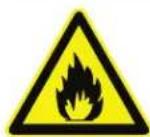
For your safety
DO NOT store or use gasoline or other flammable vapors or liquids in the vicinity of this or any other appliance.
WARNING

Improper installation, alteration, adjustment, service, cleaning, or maintenance could result in PROPERTY DAMAGE, SEVERE INJURY, or DEATH.
Read and understand the installation, operating and maintenance instructions thoroughly before installing, servicing, or operating this equipment.
W164 N9221 Water Street • P.O. Box 450
Menomonee Falls, Wisconsin 53052-0450 U.S.A.
PHONE: 262.251.3800 • 800.558.8744 U.S.A. / CANADA
FAX: 262.251.7067 • 800.329.8744 U.S.A. ONLY
www.alto-shaam.com

Consult instructions for operation and use.

MN-35947 • REV. 10 • 06/16
ALTO-SHAAM®
COMBITHERM® INSTALLATION TABLE OF CONTENTS
Delivery....1
Unpacking 1
Safety Procedures and Precautions....2
Installation
Installation Codes and Standards.... 4
Ventilation Requirements 4
Sound Pressure....4
Installation Duties and Responsibilities (new const.). 5
Installation Duties and Responsibilities (existing) ..... 6
Pre-Installation Checklist 7
Specifications, CTP6-10E 9
Specifications, CTC6-10E....10
Specifications, CTP6-10G.... 11
Specifications, CTC6-10G 12
Specifications, CTP10-10E 13
Specifications, CTC10-10E....14
Specifications, CTP10-10G.... 15
Specifications, CTC10-10G 16
Specifications, CTP7-20E 17
Specifications, CTC7-20E....18
Specifications, CTP7-20G.... 19
Specifications, CTC7-20G 20
Specifications, CTP10-20E 21
Specifications, CTC10-20E....22
Specifications, CTP10-20G.... 23
Specifications, CTC10-20G 24
Specifications, CTP20-10E 25
Specifications, CTC20-10E....26
Specifications, CTP20-10G.... 27
Specifications, CTC20-10G 28
Specifications, CTP20-20E 29
Specifications, CTC20-20E....30
Specifications, CTP20-20G.... 31
Specifications, CTC20-20G 32
Lifting Instructions....33
Clearance Requirements....34
Positioning on Site, Countertop Models 34
Positioning on Site, 20-10, 20-20 Models...... 35
Options and Accessories 36

text_image
24·7 Your Service Hotline 1-800-558-8744Electrical Safety Regulations 37
Electrical Connection for Gas Models 38
Electrical Connection for Electric Models....39
Electrical Kit Installation - 50 Hz 41
Electrical Kit Installation - 60 Hz 42
Ventilation Requirements 43
Gas Supply & Installation 44
Gas Leak Testing.... 48
Gas Exhaust....48
Water Quality Requirements 49
Water Supply & Installation 50
Water Drainage....51
Mobile Equipment Restraint.... 53
Combihood PLUS™ Installation 54
Grease Collection Hook-up.... 56
Liquid Cleaner Hook-up 57
CT PROformance Start-up Procedures .... 58
CT PROformance Screen Calibration 58
CT Classic Start-up Procedures 60
Post-Installation Checklist 61
Function Test Checklist.... 63
Preventative Maintenance.... 65
Error Codes 71
Service Parts 79
Warranty
Original Equipment Limited Warranty 80
Transportation Damage and Claims....81
Please post the following instructions in a prominent location in the event the user smells gas.
DANGER

Before starting the appliance, make certain you do not detect the odor of gas.
If you smell gas:
- Shut off the gas supply immediately.
- Do not attempt to light any appliance.
- Do not touch any electrical elements.
- Extinguish any open flame.
- Evacuate the area.
- Use a telephone outside the property and immediately contact your gas supplier.
- If unable to contact your as supplier, contact the fire department.
ALTO-SHAAM.
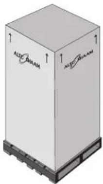
Delivery
This Alto-Shaam appliance has been thoroughly tested and inspected to ensure only the highest quality unit is provided. Upon receipt, check for any possible shipping damage and report it at once to the delivering carrier. See Transportation Damage and Claims section located in this manual.
This appliance, complete with unattached items and accessories, may be delivered in one or more packages. Ensure all standard items and options have been received with each model as ordered.
Save all the information packed with the appliance. Register online at www.alto-shaam.com to ensure prompt service in the event of a warranty parts and labor claim.
This manual must be read and understood by all people using or installing the equipment model. Contact the Alto-Shaam Tech Team Service Department if you have any questions concerning installation, operation, or maintenance.
1-800-558-8744; servicedept@alto-shaam.com
Serial number is required for all inquiries.
Always include both model and serial number(s) in any correspondence regarding the appliance.
Model:
Serial Number: ____
Purchased From:
Date Installed: ____ Voltage: ____
Unpacking
- Carefully remove the appliance from the carton or crate.
NOTICE: Do not discard the carton and other packaging material until you have inspected the unit for hidden damage and tested it for proper operation.
natural_image
3D rendering of a rectangular industrial container with 'ALTE GHAAM' branding on top and base (no text or symbols on the container itself)- Read all instructions in this manual carefully before installing this appliance, using the appliance or performing routine maintenance. Following procedures other than those indicated in this guide to use and clean the appliance is considered inappropriate and may cause damage, injury or fatal accidents, in addition to invalidating the guarantee and relieving Alto-Shaam of all liability.
- DO NOT DISCARD THIS MANUAL. This manual is considered part of the appliance and is provided for the owner or manager of the business and for training personnel. Additional manuals are available from the Alto-Shaam Tech Team Service Department.
- Remove all protective plastic film, packaging materials, and accessories from the appliance before connecting electrical power. Store any accessories in a convenient place for future use.
WARNING

Appliance and accessories may be heavy. To prevent serious injury, always use a sufficient number of trained and experienced workers when moving or leveling appliance and handling accessories.
ENVIRONMENTAL CONDITIONS
• Operational Environmental Conditions
- Unit must acclimate to room temperature in the environment it is placed. 24 hours is recommended.
- Ambient temperature range of 60^ to 110^ (16°C to 43°C).
- Relative humidity of less than 95% non-condensation.
• Atmospheric pressure range of 50KPa to 106KPa.
Safety Procedures and Precautions
- This appliance is intended to cook, hold or process foods for the purpose of human consumption. No other use for this appliance is authorized and is therefore considered dangerous. The appliance must not be used to cook food containing flammable materials (such as food with alcohol). Substances with a low flash point can ignite spontaneously and cause a fire.
- This appliance is intended for use in commercial establishments where all operators are familiar with the purpose, limitations, and associated hazards of this appliance. Operating instructions and warnings must be read and understood by all operators and users. We recommend regular training of your staff to avoid the risk of accident or damage to the unit. Operators must also receive regular safety instructions.
- Any trouble shooting guides, component views, and parts lists included in this manual are for general reference only and are intended for use by qualified and trained technicians.
- This manual should be considered a permanent part of this appliance. This manual and all supplied instructions, diagrams, schematics, parts lists, notices, and labels must remain with the appliance if the item is sold or moved to another location.
NOTICE: For equipment delivered for use in any location regulated by the following directive: 2012/95/EC WEEE
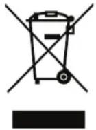
DO NOT dispose of electrical or electronic equipment with other municipal waste.
Knowledge of proper procedures is essential to the safe operation of electrically and/or gas energized equipment. The following hazard signal words and symbols may be used throughout this manual.
DANGER

Used to indicate the presence of a hazard that WILL cause severe personal injury, death, or substantial property damage if the warning included with this symbol is ignored.
WARNING

Used to indicate the presence of a hazard that CAN cause personal injury, possible death, or major property damage if the warning included with this symbol is ignored.
CAUTION

Used to indicate the presence of a hazard that can or will cause minor or moderate personal injury or property damage if the warning included with this symbol is ignored.
CAUTION
Used to indicate the presence of a hazard that can or will cause minor personal injury, property damage, or a potential unsafe practice if the warning included with this symbol is ignored.
NOTICE: Used to notify personnel of installation, operation, or maintenance information that is important but not hazard related.

Used to indicate that referral to operating instructions is a mandatory action. If not followed the operator could suffer personal injury.

Used to indicate that referral to operating instructions is recommended to understand operation of equipment.
Additional Safety Procedures and Precautions
- To prevent serious injury, death or property damage, your appliance should be inspected and serviced at least every twelve (12) months by an authorized service partner or trained technician.
- ONLY allow an authorized service partner or trained technician to service or to repair your appliance. Installation or repairs that are not performed by an authorized service partner or trained technician, or the use of non-factory authorized parts will void the warranty and relieve Alto-Shaam of all liability.
- When working on this appliance, observe precautions in the literature, on tags, on labels attached to or shipped with the appliance and other safety precautions that may apply.
- If the appliance is installed on casters freedom of movement of the appliance must be restricted so that utility connections (including gas, water, and electricity) cannot be damaged when the unit is moved. If the appliance is moved, make sure that all utility connections are properly disconnected. If the unit is returned to its original position, make sure that any retention devices and utility connections are properly connected.
- ONLY use the appliance when it is stationary. Mobile oven racks, mobile plate racks, transport trolleys, and appliances on casters can tip over when being moved over an uneven floor or threshold and cause serious injury.
- ALWAYS apply caster brakes on mobile appliances or accessories when these are not being moved. These items could move or roll on uneven floors and cause property damage or serious injury.
- Be extremely careful when moving appliances because the food trays may contain hot fluids that may spill, causing serious injury.
-
ALWAYS open the appliance door very slowly. Escaping hot vapors or steam can cause serious injury or death.
-
If your gas appliance is installed under an exhaust hood, the hood must be switched ON when the oven is in use to avoid the build up of combustion gases. Failure to do so may result in serious injury, death or property damage.
- NEVER place objects near the oven exhaust vents. This area is hot and could be a potential ignition source for a fire.
- Do not allow objects to block or obstruct the area below the oven base. This may result in fire, damage to the equipment or serious injury.
- Do not use the attached hand-held hose to spray anything other than the interior of the oven compartment.
- Do not use the attached hand-held hose on the surface of a hot cooking compartment. The sudden temperature change can damage the oven interior. Allow the oven to cool to a minimum of 150^ (66°C). Failure to observe this precaution can void the warranty.
WARNING

This appliance is not intended for use by persons (including children) with reduced physical, sensory or mental capabilities, or lack of experience and knowledge, unless they have been given supervision concerning use of the appliance by person responsible for their safety.
Children should be supervised to ensure that they do not play with the appliance.
WARNING

DO NOT obstruct or block exhaust flues or attach any flue extension that may impede proper burner operation, restrict the exhaust fumes and cause negative backdraft or the appliance to shut down. Failure to do so may result in serious injury or death.
INSTALLATION
SITE INSTALLATION
WARNING

Improper installation, alteration, adjustment, service, cleaning, or maintenance could result in PROPERTY DAMAGE, SEVERE INJURY, or DEATH.
Read and understand the installation, operating and maintenance instructions thoroughly before installing, servicing, or operating this equipment.
AVERTISSEMENT

The following codes and standards are required for installation of this oven:
AIR SUPPLY, ELECTRICAL CONNECTIONS, WATER CONNECTIONS, AND WASTE WATER DISCHARGE.
Installation must comply with local codes required for gas appliances. In the absence of local codes, installation must comply with the National Fuel Gas Code, ANSI Z223.1 (latest edition). In Canada, the appropriate code is the Natural Gas Installation Code, CAN/CGA-B149.1 or the Propane Installation Code, CAN/CGA-B. Adherence to code by a qualified installer is essential for the following: Gas Plumbing, Gas Appliance Installation, Commercial Cooking Ventilation, Water and Plumbing, and OSHA Regulations and European Standard EN203.
! WARNING

To prevent serious injury, death, or property damage, always disconnect appliance from power source before cleaning or servicing.
CAUTION

ALWAYS remove the electronic control boards BEFORE welding any stainless steel components on this appliance. Failure to do so will damage the control boards and may void the warranty.
VENTILATION REQUIREMENTS
A steam ventilation hood is mandatory for the operation of the oven. In addition, a single gas Combitherm oven requires a minimum of 28 CFM make-up air for both natural and propane gas. Authorities having jurisdiction should be consulted as to the requirements for this equipment with respect to ventilation and fire extinguishing systems to ensure conformity with any Federal, State, or local installation codes.
See the section titled Gas Exhaust.
SOUND PRESSURE MEASUREMENTS
The A-weighted sound pressure level without ventless hood operating is less than 70dBA.
New Construction
| Designer/Consultant Responsibilities: Pre-Installation | |
| Complete water analysis to be conducted to ensure water quality meets manufacture specifications. | |
| Proper floor drain within 3' (914mm), not directly underneath, of where the appliance is to be installed. | |
| Minimum of one (1) 3/4" cold water supply line-two (2) recommended-with 3/4" shut off valve installed ahead of a minimum of two (2) 3/4" NPT connections. | |
| Gas appliances require one 3/4" line within 3' (914mm) of the appliance equipped with a manual shut off, and ready to be hooked to a 3/4" quick disconnect hose. | |
| Vent hood, and possible interconnection with gas supply as determined by local code. | |
| Proper electrical voltage, phase, wire size, breaker size, and disconnects are provided for hook ups within 3' (914mm) of the appliance. | |
| Exhaust air for gas appliances, exhaust hood, ventilation ceiling, chimney, spacing from top edge of appliance to lower edge of grease filters/ceiling. | |
| If floor is to be sloped then level surface must be provided for trolley/cart appliances. | |
| Confirm clearances of hallways, and doors to the installation area are sufficient for the model of the appliance being installed. | |
| Installer Responsibilities: Pre-Installation | |
| Pre-Installation check sheet has been properly filled out. | |
| Inspect, receive, deliver, uncrate, and set appliance in place. | |
| Installer Responsibilities: Installation | |
| Check that the appliance is level. Follow leveling instructions found in the installation manual. | |
| Make final water connections to both 3/4" cold water lines with required 30 psi minimum dynamic and 90 psi maximum static (2.1–6.3 bar) making sure treated and untreated are hooked up properly to the correct fittings. | |
| Hook up final electrical, check for proper voltage, phase, wire size, and breaker size. Ground fault or residual current protection device must accommodate a leakage current of 20mA. Report any issues to the designer / consultant. | |
| Plumb in the appliance drain per the required specifications found in the installation manual. | |
| Ensure gas pressure is above minimum and below maximum pressures listed in the installation manual for the corresponding gas type. | |
| Check that all accessories are unpackaged and set up for the end user. | |
| Ensure combi appliance is properly fastened to the ground, or has a restraint installed if on casters. | |
| Test that the CombiOven is fully operational, report any issues or manufacturing defects. | |
| Ensure most current soft ware is installed. | |
| Pick up any packaging trash and debris from the installation. | |
| Clean and wipe down the outside of the appliance and make presentable to the end user. | |
| Take pictures of the installation verifying proper drain, water lines, and clearances are met. | |
| ASA Responsibilities: After Install | |
| Perform mechanical startup. | |
| Complete post installation check sheet. | |
| Pictures of the install's electrical connections, water, drain, and clearances should be taken and sent to: installation_program@alto-shaam.com | |
| RSP/Dealer: After Install | |
| Confirm installation is correct. | |
| Provide operational training and demonstration, and contact information for post installation support. | |
| Verify warranty registration documentation has been submitted. | |
| Customer/End User | |
| Complete and submit warranty registration documentation: www.alto-shaam.com/warranty | |
| Use the appliance only for its intended purpose. | |
| Follow cleaning and planned maintenance schedules to maximize the life of the equipment. | |
Retro Fit/Existing Kitchen
| Designer/Consultant Responsibilities: Pre-Installation | |
| Complete water analysis to be conducted to ensure water quality meets manufacture specifications. | |
| Proper floor drain within 3' (914mm), not directly underneath, of where the appliance is to be installed. | |
| Minimum of one (1) 3/4" cold water supply line-two (2) recommended-with 3/4" shut off valve installed ahead of a minimum of two (2) 3/4" NPT connections. | |
| Gas appliances require one 3/4" line within 3' (914mm) of the appliance equipped with a manual shut off, and ready to be hooked to a 3/4" quick disconnect hose. | |
| Proper vent hood is installed, and possible interconnection with gas supply per by local code. | |
| Proper electrical voltage, phase, wire size, breaker size, and disconnects are provided for hook ups within 3' (914mm) of the appliance. | |
| Exhaust air for gas appliances, exhaust hood, ventilation ceiling, chimney, spacing from top edge of appliance to lower edge of grease filters/ceiling. | |
| If floor is to be sloped then level surface must be provided for trolley/cart appliances. | |
| Confirm clearances of hallways, and doors to the installation area are sufficient for the model of the appliance being installed. | |
| Installer Responsibilities: Pre-Installation | |
| Pre-Installation check sheet has been properly filled out. | |
| Installer Responsibilities: Installation | |
| Inspect, receive, deliver, uncrate, set appliance in place, and check that appliance is level. | |
| Make final water connections to 3/4" cold water lines with required 30 psi minimum dynamic and 90 psi maximum static (2.1–6.3 bar) making sure treated and untreated are hooked up properly to the right fittings. | |
| Hook up final electrical, check for proper voltage, phase, wire size, and breaker size. Ground fault or residual current protection device must accommodate a leakage current of 20mA. Report any issues to the designer / consultant. | |
| Plumb in the appliance steam resistant drain per manufactures required specifications as found in the installation manual. | |
| Ensure gas pressure is above minimum and below maximum pressures listed in the installation manual for the corresponding gas type. | |
| Check that all accessories are unpackaged and set up for the end user. | |
| Ensure Combi appliance is properly fastened to the ground, or has a restraint installed if on casters. | |
| Ensure most current soft ware is installed / uploaded. | |
| Verify installation meets the manufacture specifications per the installation manual. | |
| Test that the Combi appliance is fully operational, report any issues or manufacturing defects. | |
| Pick up any packaging trash and debris from the installation. | |
| Clean and wipe down the outside of the appliance and make presentable to the end user. | |
| Take pictures of the installation verifying proper drain, water lines, and clearances are met. | |
| ASA Responsibilities: After Install | |
| Perform mechanical startup. | |
| Complete post installation check sheet. | |
| Pictures of the install's electrical connections, water, drain, and clearances should be taken and sent to: installation_program@alto-shaam.com | |
| RSP/Dealer: After Install | |
| Confirm installation is correct. | |
| Provide operational training and demonstration, and contact information for post installation support. | |
| Verify warranty registration documentation has been submitted. | |
| Customer/End User | |
| Complete and submit warranty registration documentation. | |
| Use the appliance only for its intended purpose. | |
| Follow cleaning and planned maintenance schedules to maximize the life of the equipment. | |
Factory Authorized Combitherm® Installation Program PRE-INSTALLATION CHECKLIST
Location Name: ____
Site Contact Name: ____
Location Street Address: ____
Site Contact Phone No.:
Location City: ____
Location State: ____ Zip: ____
Pre-Installation Company Information
Company Name: ____
Technician Name: ____
Mailing Address: ____
Technician Phone No.:
City:
Contact Email: ____
State: ____ Zip: ____
| Number of combis to be installed | ||||
| Model number(s) of combi's to be installed | ||||
| Serial number of combi's to be installed | ||||
Clearance
| Measure door/entry way clearance (smallest dimension) PASS FAIL | ||||||
| Measure path clearance (smallest dimension) PASS FAIL | ||||||
| Elevator opening, if applicable (smallest dimension) PASS FAIL | ||||||
| Elevator interior dimensions, if applicable (HxWxD) PASS FAIL | ||||||
| Appliance clearance Right side PASS FAIL | ||||||
| Left side PASS FAIL | ||||||
| Rear | PASS FAIL | |||||
| Top | PASS | FAIL | ||||
| Based on the appliances designated spot in the kitchen, would the appliance be accessible for service? | YES | NO | ||||
| If NO, comment on the issue: | ||||||
Water Supply
| Is there at least one 3/4" cold water supply line within 3 feet of where each appliance will be installed? | PASS | FAIL:DESCRIBE ISSUE | ||||
| Do water supply line(s) have shut-off(s) exclusively for each oven? | PASS | FAIL:DESCRIBE ISSUE | ||||
| Do water supply line(s) provide a total two hookups per appliance, terminated with male NPT fittings? | PASS | FAIL:DESCRIBE ISSUE | ||||
| Is the dynamic water pressure from the 3/4" cold water supply line a minimum of 30 psi for each appliance? | PASS | FAIL | UNKNOWN | |||
| Is the static water pressure from the 3/4" cold water supply line less than 90 psi for each appliance? | PASS | FAIL | UNKNOWN | |||
| Is water treatment (RO blend system, filter, etc.) being used? | YES | NO | UNKNOWN | |||
| If YES - Note the system here: | BRAND NAME | MODEL | ||||
| Can the site contact provide evidence that a documented water analysis has been performed? | YES | NO | ||||
Factory Authorized Combitherm® Installation Program
PRE-INSTALLATION CHECKLIST
| Electrical | ||||||||
| What is the rated voltage and phase of the oven(s) to be supplied? | VOLTAGE PHASE | |||||||
| What is the measured voltage at site? L1-N L2-N L3-N L1-L2 | ||||||||
| L2-3 L | 1-L3 PASS FAIL | |||||||
| What is the current draw of the oven(s) to be supplied? | AMP RATING | |||||||
| What is the on-site breaker size supplying power to the oven(s)? | SIZE PASS FAIL | |||||||
| Is there a disconnect or junction box within 3' (914mm) of where the oven(s) will be installed? | PASS FAIL | |||||||
| Comments: | ||||||||
| Gas | ||||||||
| What is the gas type for the oven(s) to be installed? | NATURAL PROPANE | |||||||
| What is the gas type confirmed at installation site? | NAT PRO PASS FAIL | |||||||
| Is there a minimum of one 3/4" gas supply line within 3' (914mm) of where the oven(s) will be installed | PASS FAIL | |||||||
| On the gas line, is there a 3/4" NPT pipe connection with a shut-off valve within 3' (914mm) of where the oven(s) will be installed? | PASS FAIL | |||||||
| Comments: | ||||||||
| Drain | ||||||||
| Is there a floor drain within 3' (914mm) of where the oven(s) will be installed? | PASS FAIL | |||||||
| What is the actual distance to floor drain from where the oven(s) will be installed? | MEASUREMENT | PASS FAIL | ||||||
| Is the drain going to be located underneath the oven(s) that will be installed? (The drain should not be located directly under the oven — a No answer would = Pass) | PASS FAIL | |||||||
| Comments: | ||||||||
| Other site information | ||||||||
| Is there a proper ventilation hood installed above where the oven(s) will be installed? | PASS FAIL | |||||||
| Based on the designated location in the kitchen, is the floor level to the point that proper leveling of the oven(s) will be possible? | PASS FAIL | |||||||
| Is the site 100% ready for oven(s) installation? | PASS FAIL | |||||||
| Is site action required? | PASS FAIL | |||||||
| Action Required: | ||||||||
| Comments: | ||||||||
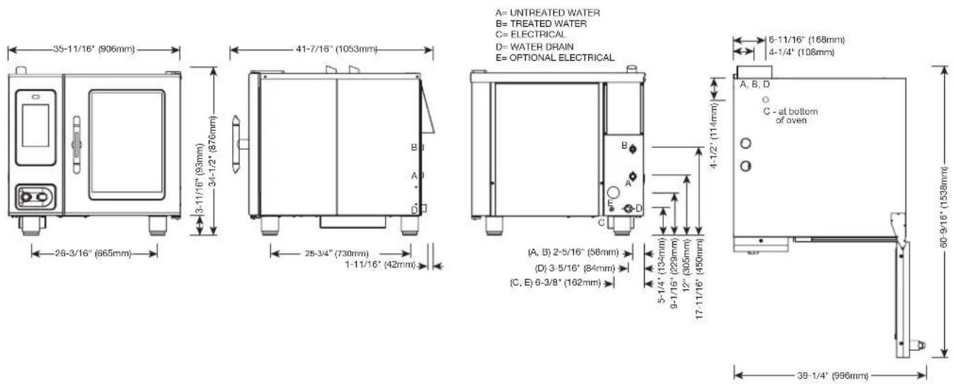
ELECTRIC BOILER
text_image
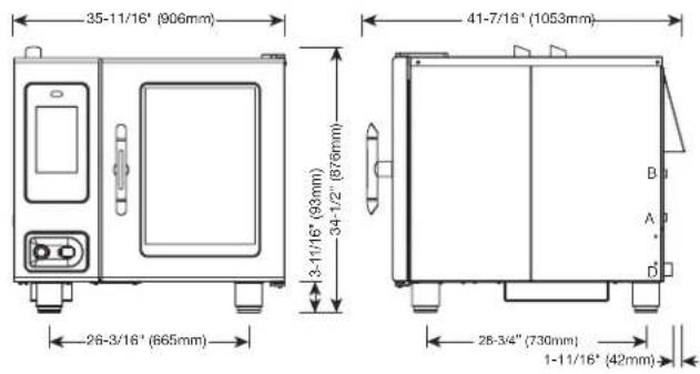
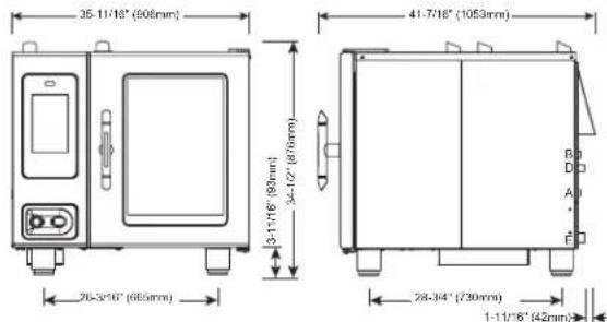
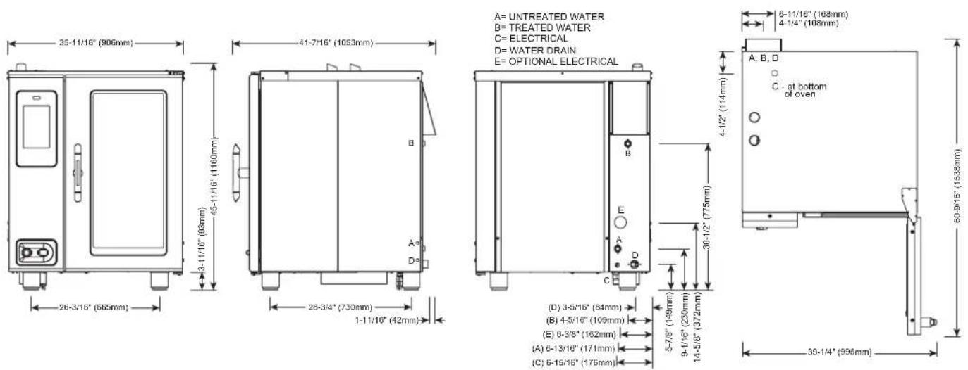
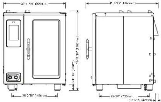
35-11/16" (906mm) 41-7/16" (1053mm) 3-11/16" (93mm) 34-1/2" (876mm) 26-3/16" (665mm) 28-3/4" (730mm) 1-11/16" (42mm)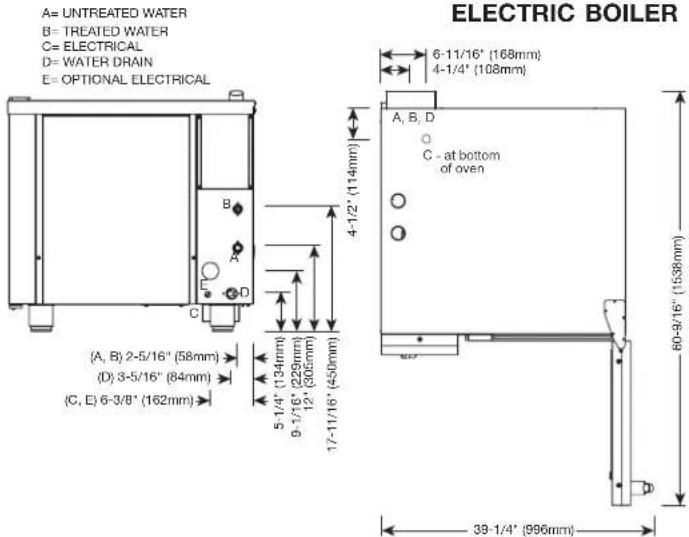
text_image
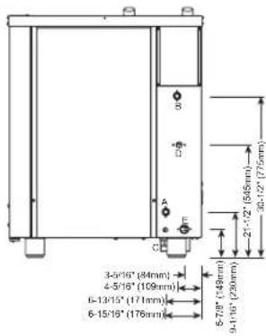
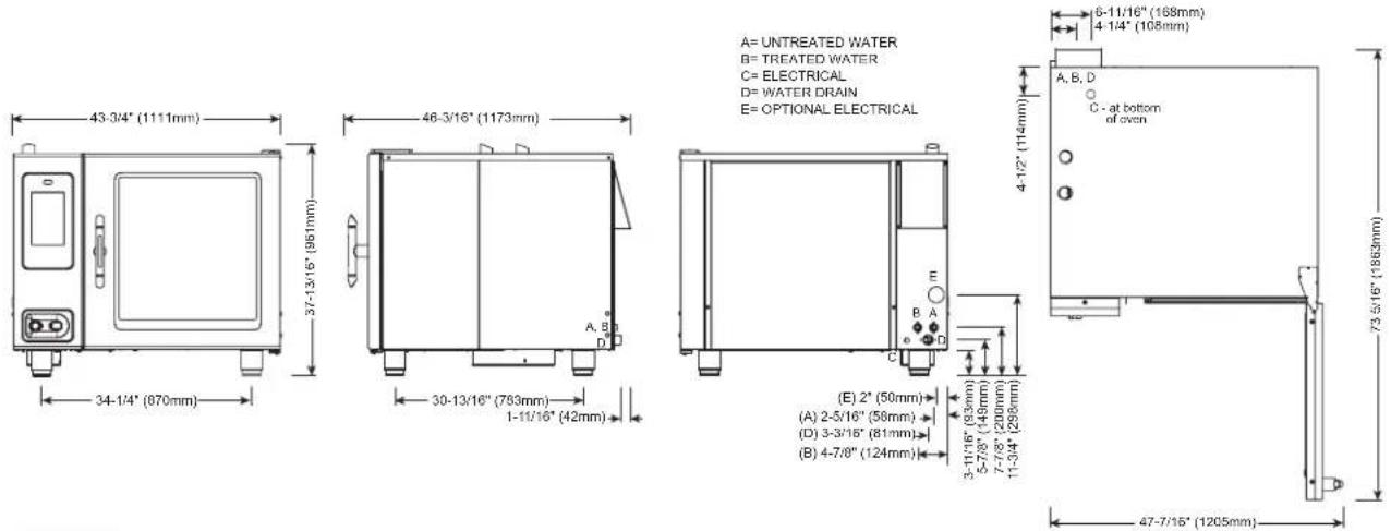
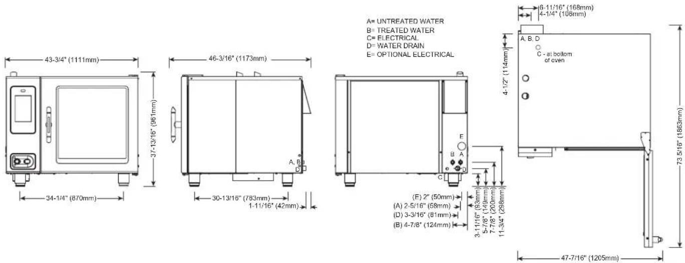
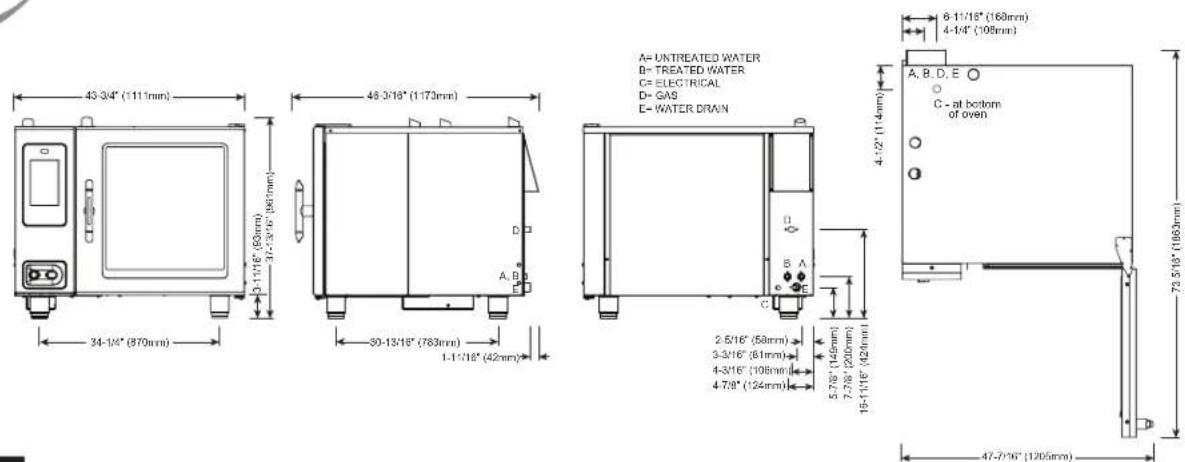
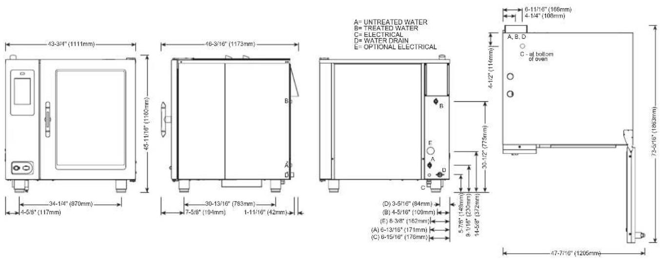
A= UNTREATED WATER B= TREATED WATER C= ELECTRICAL D= WATER DRAIN E= OPTIONAL ELECTRICAL (A, B) 2-5/16" (58mm) (D) 3-5/16" (84mm) (C, E) 6-3/8" (162mm) ELECTRIC BOILER 6-11/16" (168mm) 4-1/4" (108mm) A, B, D C - at bottom of oven 5-1/4" (134mm) 9-1/16" (229mm) 12" (305mm) 17-11/16" (450mm) 39-1/4" (996mm) 60-9/16" (1538mm)

CE EAC IP X5
WATER REQUIREMENTS
| TWO (2) COLD WATER INLETS - DRINKING QUALITYONE (1) TREATED WATER INLET: 3/4" NPT* * Can manifold off ofONE (1) UNTREATED WATER INLET: 3/4" NPT* one 3/4" lineLINE PRESSURE: 30 psi minimum dynamic and 90 psi maximum static (200 to 600 kPa)WATER DRAIN: 1-1/2" (40mm) CONNECTION WITH A VERTICAL VENT TO EXTEND ABOVE THE EXHAUST VENT,MATERIALS MUST WITHSTAND TEMPERATURES UP TO 200°F (93°C). | |
| CLEARANCE REQUIREMENTS | |
| LEFT: 0" (0mm) | 18" (457mm) RECOMMENDED SERVICE ACCESS |
| RIGHT: 0" (0mm) NON-COMBUSTIBLE SURFACES | 2" (51mm) DOOR SWING ORCOMBUSTIBLE SURFACES |
| TOP: 20" (508mm) FOR AIR MOVEMENT | |
| BACK: 4" (102mm)4-5/16" (109mm) OPTIONAL PLUMBING KIT | BOTTOM: 5-1/8" (130mm)FOR LEGS, AIR INTAKE |
| INSTALLATION REQUIREMENTS | |
| • Oven must be installed level. • Hood installation is required.• Water supply shut-off valve and back-flow preventer when required by local code. | |
| ELECTRICAL - CTP6-10E (NO CORD, NO PLUG, DEDICATED CIRCUIT REQUIRED) | WITH COMBISMOKER ^ OPTION | ||||||||||||||||
| ECO STANDARD | **PROpower ^TM OPTION | ECO STANDARD | **PROpower ^TM OPTION | ||||||||||||||
| VOLTAGE | PH | HZ | AWG | CONNECTION | AMPS | KW | BREAKER | AMPS | KW | BREAKER | AMPS | KW | BREAKER | AMPS | KW | BREAKER | |
| 208 – 240 | 1* | 50/60 | 6 | L1, L2/N, G | 37.9 – 43.8 | 7.9 – 10.5 | 40 – 50 | 44.2 – 51.3 | 9.2 – 12.3 | 45 – 60 | 40.4 – 46.6 | 8.4 – 11.2 | 40 – 50 | 46.7 – 54.1 | 9.7 – 13 | 50 – 60 | |
| 208 – 240 | 3 | 50/60 | 8 | L1, L2, L3, G | 21.9 – 25.3 | 7.9 – 10.5 | 25 – 30 | 28.4 – 32.6 | 9.2 – 12.3 | 30 – 35 | 24.4 – 28.1 | 8.4 – 11.2 | 25 – 30 | 30.9 – 35.5 | 9.8 – 13 | 35 – 40 | |
| 380 – 415 | 3 | 50/60 | 8 | L1, L2, L3, N, G | 13.4 – 14.6 | 9 – 10.5 | 16 | 20.3 – 22.1 | 10.3 – 12.3 | 32 | 16.1 – 17.5 | 9.6 – 11.2 | 16 – 32 | 22.9 – 25 | 10.9 – 13 | 32 | |
| 440 – 480 | 3* | 50/60 | 10 – 8 | L1, L2, L3, G | 11.6 – 12.6 | 9.1 – 10.5 | 15 | 15 – 16.7 | 10.4 – 12.3 | 15 – 20 | 12.9 – 14.1 | 9.6 – 11.2 | 15 | 16.3 – 18.2 | 11 – 13 | 20 | |
*ELECTRICAL SERVICE CHARGE APPLIES
**NO-COST OPTION ON ELECTRIC MODELS
| WEIGHT | PAN CAPACITY | STANDARD MODEL | WITH COMBISMOKER® OPTION | ||
| NET | 524 lbs EST | 238 kg | FULL-SIZE: 20" x 12" x 2-1/2" | Seven (7) | Six (6) |
| SHIP | 608 lbs* | 276 kg* | GN 1/1: 530 x 325 x 65mm | Seven (7) | Six (6) |
| **HALF-SIZE SHEET: 18" x 13" x 1" | Seven (7) | Seven (7) | |||
| SHIP DIMENSIONS | PRODUCT CAPACITY | ||||
| (L x W x H) 58" x 45" x 51"*(1473mm x 1143mm x 1295mm)* | PRODUCT MAXIMUM | 72 lb (33 kg) | |||
| VOLUME MAXIMUM | 45 quarts (57 liters) | ||||
| *DOMESTIC GROUNDSHIPPING INFORMATION CONTACTFACTORY FOREXPORT WEIGHT ANDDIMENSIONS. | **ON WIRE SHELVES ONLY. ADDITIONAL WIRE SHELVES REQUIRED FOR MAXIMUM CAPACITY | ||||
text_image
35-11/16" (906mm) 41-7/16" (1053mm) 26-3/16" (665mm) 34-1/2" (876mm) 28-3/4" (730mm) 1-11/16" (42mm) A= UNTREATED WATER B= TREATED WATER C= ELECTRICAL D= WATER DRAIN E= OPTIONAL ELECTRICAL (A, B) 2-5/16" (58mm) (D) 3-5/16" (84mm) (C, E) 6-3/8" (162mm) 5-1/4" (134mm) 9-1/16" (229mm) 12" (305mm) 17-11/16" (450mm) 6-11/16" (168mm) 4-1/4" (106mm) A, B, D C - at bottom of oven 39-1/4" (996mm)

CE EAC IP X5
| WATER REQUIREMENTS | WATER QUALITY STANDARDS | ||||
| TWO (2) COLD WATER INLETS - DRINKING QUALITYONE (1) TREATED WATER INLET: 3/4" NPT* * Can manifold off ofONE (1) UNTREATED WATER INLET: 3/4" NPT* one 3/4" LineLINE PRESSURE: 30 psi minimum dynamic and 90 psi maximum static (200 to 600 kPa)WATER DRAIN: 1-1/2" (40mm) CONNECTION WITH A VERTICAL VENT TO EXTEND ABOVE THE EXHAUST VENT.MATERIALS MUST WITHSTAND TEMPERATURES UP TO 200°F (93°C). | It is the sole responsibility of the owner/operator/purchaser of this equipment to verify that the incoming water supply is comprehensively tested and if required, a means of "water treatment" provided that would meet compliance requirements with the published water quality standards shown below.Non-compliance with these minimum standards will potentially damage this equipment and/or components and void the original equipment manufacturer's warranty. Alto-Shaam recommends using OptiPure® [www.optipurewater.com] products to properly treat your water.Contaminant Inlet Water RequirementsFree Chlorine Less than 0.1 ppm (mg/L)Hardness 30-70 ppmChloride Less than 30 ppm (mg/L)pH 7.0 to 8.5Silica Less than 12 ppm (mg/L)Total Dissolved Solids (tds) 50-125 ppm | ||||
| CLEARANCE REQUIREMENTS | |||||
| LEFT: 0" (0mm) | 18" (457mm) RECOMMENDED SERVICE ACCESS | ||||
| RIGHT: 0" (0mm) NON-COMBUSTIBLE SURFACES | 2" (51mm)DOOR SWING OR COMBUSTIBLE SURFACES | ||||
| TOP: 20" (508mm) FOR AIR MOVEMENT | |||||
| BACK: 4" (102mm)4-5/16" (109mm) OPTIONAL PLUMBING KIT | BOTTOM: 5-1/8" (130mm)FOR LEGS, AIR INTAKE | ||||
| INSTALLATION REQUIREMENTS | |||||
| • Oven must be installed level. • Hood installation is required.• Water supply shut-off valve and back-flow preventer when required by local code. | |||||
| ELECTRICAL (NO CORD, NO PLUG - DEDICATED CIRCUIT REQUIRED) | |||||
| MODEL VOLTAGE PH HZ AMPS KW BREAKER AWG CONNECTION | |||||
| CTC6-10E | 208-240 3 50/60 21.9-25.3 7.9-10.5 25-30 8 L1, L2, L3, G | ||||
| 380-415 3 50/60 13.4-14.6 9.0-10.5 16 8 L1, L2, L3, N, G | |||||
| 440-480 3* 50/60 11.6-12.6 9.1-10.5 | 15 | 10-8 | L1, L2, L3, G | ||
*ELECTRICAL SERVICE CHARGE APPLIES
| WEIGHT | SHIP DIMENSIONS | PAN CAPACITY | |||||
| NET | 524 lbs est | 238 kg | (L x W x H) 58" x 45" x 51** | FULL-SIZE: | 20" x 12" x 2-1/2" | Seven (7) | PRODUCT MAXIMUM: 72 lb (33 kg) |
| SHIP | 608 lbs* | 276 kg* | (1473 x 1143 x 1295mm)* | GN 1/1: | 530 x 325 x 65mm | Seven (7) | VOLUME MAXIMUM: 45 quarts (57 liters) |
| *DOMESTIC GROUND SHIPPING INFORMATION. CONTACT FACTORY FOR EXPORT WEIGHT AND DIMENSIONS. | *HALF-SIZE SHEET: | 18" x 13" x 1" | Seven (7) | **ON WIRE SHELVES ONLY, ADDITIONAL WIRE SHELVES REQUIRED FOR MAXIMUM CAPACITY | |||

text_image
35-11/16" (300mm) 41-7/16" (1053mm) 26-3/16" (665mm) 28-3/4" (730mm) 1-11/16" (42mm)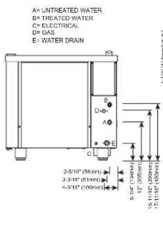
text_image
A= UNTREATED WATER B= TREATED WATER C= ELECTRICAL D= GAS E= WATER DRAIN 2-5/10" (58mm) 3-3/10" (61mm) 4-3/10" (106mm) 5-10" (134mm) 12" (505mm) 15-11/10" (999mm) 17-11/10" (450mm)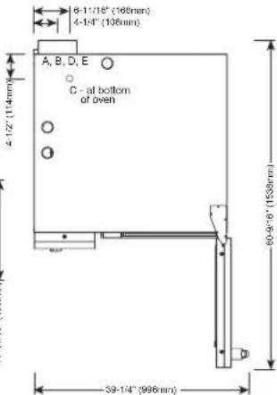
text_image
6-11/18" (168mm) 4-14" (108mm) A, B, D, E C - at bottom of oven 39-14" (996mm)


WATER REQUIREMENTS
| TWO (2) COLD WATER INLETS - DRINKING QUALITYONE (1) TREATED WATER INLET: 3/4" NPT* * Can manifold off ofONE (1) UNTREATED WATER INLET: 3/4" NPT* one 3/4" lineLINE PRESSURE: 30 psi minimum dynamic and 90 psi maximum static (200 to 600 kPa)WATER DRAIN: 1-1/2" (40mm) CONNECTION WITH A VERTICAL VENT TO EXTEND ABOVE THE EXHAUST VENT.MATERIALS MUST WITHSTAND TEMPERATURES UP TO 200°F (93°C). | |
| CLEARANCE REQUIREMENTS | |
| LEFT: 0" (0mm) | 18" (457mm) RECOMMENDED SERVICE ACCESS |
| RIGHT: 0" (0mm) NON-COMBUSTIBLE SURFACES | 2" (51mm) DOOR SWING ORCOMBUSTIBLE SURFACES |
| TOP: 20" (508mm) FOR AIR MOVEMENT | |
| BACK: 4" (102mm)4-5/16" (109mm) OPTIONAL PLUMBING KIT | BOTTOM: 5-1/8" (130mm)FOR LEGS, AIR INTAKE |
INSTALLATION REQUIREMENTS
| • Oven must be installed level. | • Hood installation is required. |
| • Water supply shut-off valve and back-flow preventer when required by local code. | |
GAS REQUIREMENTS (GAS TYPE MUST BE SPECIFIED ON ORDER)
| HOOK-UP: 3/4" NPT | ||||||||||||
| RATED THERMAL LOAD CONNECTED PRESSURE | ||||||||||||
| NORTH AMERICA INTERNATIONAL NORTH AMERICA INTERNATIONAL | ||||||||||||
| Natural Gas/Propane G20, G25, G31 Natural Gas Propane | G20 20mbar | |||||||||||
| Gross Heating Value (HHV) Net Heating Value (LHV) Minimum: 5.5" W.C. dynamic Minimum: 9" W.C. dynamic | G25 20mbar | |||||||||||
| 48,000 Btu / hr | 13.0 kW | Maximum: 14" W.C. static | Maximum: 14" W.C. static | G31 30mbar | ||||||||
| ELECTRICAL - CTP6-10G (DEDICATED CIRCUIT REQUIRED) | WITH COMBISMOKER®OPTION | |||||||||||
| VOLTAGE | PH | HZ | AWG | CONNECTION no cord, no plug | AMPS | BREAKER | kW | CONNECTION no cord, no plug | AMPS | BREAKER | kW | |
| ←→ | 120 | 1 | 60 | 14 | L1, N, G | 6.8 | 20 | .84 | L1, N, G | 12.0 | 20 | 1.46 |
| ←→ | 208 – 240 | 1+ | 50/60 | 14 | L1, L2/N, G | 4.8 – 4.2 | 15 | 1.0 | L1, L2/N, G | 7.3 – 7.1 | 15 | 1.5 – 1.7 |
| ←→ | 208 – 240 | 3 | 50/60 | 14 | L1, L2, L3, G | 4.8 – 4.2 | 15 | 1.0 | L1, L2, L3, G | 7.3 – 7.1 | 15 | 1.5 – 1.7 |
| ←→ | 380 – 415 | 3 | 50/60 | 14 | L1, L2, L3, N, G | 4.6 – 4.2 | 15 | 1.0 | L1, L2, L3, N, G | 7.2 – 7.1 | 15 | 1.6 – 1.7 |
NORTH AMERICA VOLTAGE CHOICE GROUND FAULT OR RESIDUAL CURRENT PROTECTION DEVICEMUST ACCOMMODATE A LEAVAGE CURRENT OF 20mA INTERNATIONAL VOLTAGE CHOICE ELECTRICAL SERVICE CHARGE APPLIES
| WEIGHT | PAN CAPACITY | STANDARD MODEL | WITH COMBISMOKER® OPTION | ||
| NET | 524 lbs est | 238 kg | FULL-SIZE: 20" x 12" x 2-1/2" | Seven (7) | Six (6) |
| SHIP | 581 lbs* | 264 kg* | GN 1/1: 530 x 325 x 65mm**HALF-SIZE SHEET: 18" x 13" x 1" | Seven (7) | Six (6) |
| Seven (7) | Seven (7) | ||||
| SHIP DIMENSIONS | PRODUCT CAPACITY | ||||
| (L x W x H) 51" x 45" x 51**(1295mm x 1143mm x 1295mm)* | PRODUCT MAXIMUM | 72 lb (33 kg) | |||
| VOLUME MAXIMUM | 45 quarts (57 liters) | ||||
| *DOMESTIC GROUND SHIPPING INFORMATION. CONTACT FACTORY FOR EXPORT WEIGHT AND DIMENSIONS. | **ON WIRE SHELVES ONLY. ADDITIONAL WIRE SHELVES REQUIRED FOR MAXIMUM CAPACITY | ||||
text_image
25-11/18" (606mm) 41-7/16" (1053mm) 26-3/16" (685mm) 28-34" (730mm) 1-11/16" (42mm)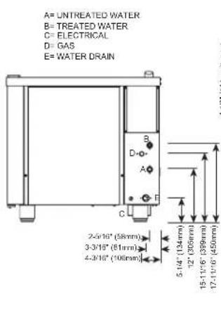
text_image
A= UNTREATED WATER B= TREATED WATER C= ELECTRICAL D= GAS E= WATER DRAIN 2-5/16" (58mm) 3-3/16" (61mm) 4-3/16" (106mm) 5-14" (134mm) 12" (305mm) 15-11/6" (399mm) 17-11/6" (450mm)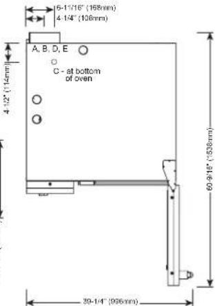
text_image
15-11/16" (168mm) 4-14" (108mm) A, B, D, E C - at bottom of oven 4-12" (114mm) 60-918" (938mm) 30-14" (996mm)
COOKING APPLIANCE
\$10m

ANSI/NSF 4


IP X5

| WATER REQUIREMENTS | WATER QUALITY STANDARDS | ||||||||
| TWO (2) COLD WATER INLETS - DRINKING QUALITYONE (1) TREATED WATER INLET: 3/4" NPT* * Can manifold off ofONE (1) UNTREATED WATER INLET: 3/4" NPT* one 3/4" lineLINE PRESSURE: 30 psi minimum dynamic and 90 psi maximum static (200 to 600 kPa)WATER DRAIN: 1-1/2" (40mm) CONNECTION WITH A VERTICAL VENT TO EXTEND ABOVE THE EXHAUST VENT.MATERIALS MUST WITHSTAND TEMPERATURES UP TO 200°F (93°C). | It is the sole responsibility of the owner/operator/purchaser of this equipment to verify that the incoming water supply is comprehensively tested and if required, a means of "water treatment" provided that would meet compliance requirements with the published water quality standards shown below.Non-compliance with these minimum standards will potentially damage this equipment and/or components and void the original equipment manufacturer's warranty. Alto-Shaam recommends using OptiPure® [www.optipurewater.com] products to properly treat your water.Contaminant Inlet Water RequirementsFree Chlorine Less than 0.1 ppm (mg/L)Hardness 30-70 ppmChloride Less than 30 ppm (mg/L)pH 7.0 to 8.5Silica Less than 12 ppm (mg/L)Total Dissolved Solids (tds) 50-125 ppm | ||||||||
| CLEARANCE REQUIREMENTS | |||||||||
| LEFT: 0" (0mm) | 18" (457mm) RECOMMENDED SERVICE ACCESS | ||||||||
| RIGHT: 0" (0mm) NON-COMBUSTIBLE SURFACES | 2" (51mm) DOOR SWING OR COMBUSTIBLE SURFACES | ||||||||
| TOP: 20" (508mm) FOR AIR MOVEMENT | |||||||||
| BACK: 4" (102mm)4-5/16" (109mm) OPTIONAL PLUMBING KIT | BOTTOM: 5-1/8" (130mm)FOR LEGS, AIR INTAKE | ||||||||
| INSTALLATION REQUIREMENTS | |||||||||
| · Oven must be installed level. · Hood installation is required.· Water supply shut-off valve and back-flow preventer when required by local code. | |||||||||
| GAS REQUIREMENTS (GAS TYPE MUST BE SPECIFIED ON ORDER) | |||||||||
| HOOK-UP: 3/4" NPT | |||||||||
| RATED THERMAL LOAD CONNECTED PRESSURE | |||||||||
| NORTH AMERICA INTERNATIONAL NORTH AMERICA INTERNATIONAL | |||||||||
| Natural Gas/Propane G20, G25, G31 Natural Gas Propane | G20 20mbar | ||||||||
| Gross Heating Value (HHV) Net43,000 Btu / hr | Heating Value (LHV) Minimum: 5.5" W.C. dynamic Minimum: 9" W.C. dynamicMaximum: 14" W.C. static Maximum: 14" W.C. static | G25 20mbarG31 30mbar | |||||||
| ELECTRICAL - CTC6-10G (DEDICATED CIRCUIT REQUIRED) | |||||||||
| VOLTAGE | PH | HZ | AWG | CONNECTION | AMPS | BREAKER | kW | ||
| <> | 120 | 1 | 60 | 14 | L1, N, G - no cord, no plug | 7.0 | 20 | .84 | |
| <> | 208 – 240 | 3 | 50/60 | 14 | L1, L2, L3, G - no cord, no plug | 4.8 – 4.2 | 15 | 1.0 | |
| <> | 380 – 415 | 3 | 50/60 | 14 | L1, L2, L3, N, G - no cord, no plug | 4.6 – 4.2 | 15 | 1.0 | |
NORTH AMERICA VOLTAGECHOICE GROUND FAULT OR RESIDUAL CURRENT PROTECTION DEVICE MUST ACCOMMODATE A LEAKAGE CURRENT OF 20mA INTERNATIONAL VOLTAGECHOICE
| WEIGHT SHIP DIMENSIONS | PAN CAPACITY | ||||
| NET 524 lbs est 238 kgSHIP 581 lbs* 264 kg* | (L x W x H) 51" x 45" x 51**(1295 x 1143 x 1295mm)* | FULL-SIZE: 20" x 12" x 2-1/2"GN 1/1: 530 x 325 x 65mm**HALF-SIZE SHEET: 18" x 13" x 1" | Seven (7)Seven (7) | PRODUCT MAXIMUM: 72 lb (33 kg)VOLUME MAXIMUM: 45 quarts (57 liters)**ON WIRE SHELVES ONLY, ADDITIONAL WRESHELVES REQUIRED FOR MAXIMUM CAPACITY | |
| *DOMESTIC GROUND SHIPPING INFORMATION. CONTACT FACTORY FOREXPORT WEIGHT AND DIMENSIONS. | |||||
ELECTRIC BOILER
text_image
35-11/16" (906mm) 41-7/16" (1053mm) 26-3/16" (605mm) 3 11/16" (93mm) 45-11/16" (1100mm) 28-3/4" (730mm) 1-11/16" (42mm)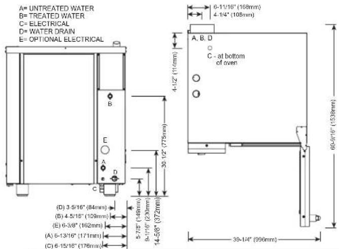
text_image
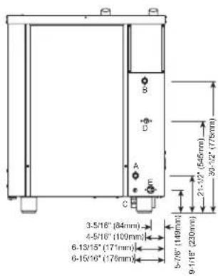
A= UNTREATED WATER B= TREATED WATER C= ELECTRICAL D= WATER DRAIN E= OPTIONAL ELECTRICAL (B) 3-5/16" (84mm) (B) 4-5/16" (109mm) (E) 6-3/8" (102mm) (A) 6-13/16" (171mm) (C) 6-15/16" (176mm) 4-1/2" (114mm) 30 1/2" (775mm) 5-7/8" (148mm) 9-11/6" (230mm) 14-5/8" (372mm) 6-11/16" (168mm) 4-1/4" (108mm) A, B, D C - at bottom of oven 60-9/16" (1538mm) 39-1/4" (996mm)

CE EAC IP X5
| WATER REQUIREMENTS | WATER QUALITY STANDARDS | ||
| TWO (2) COLD WATER INLETS - DRINKING QUALITYONE (1) TREATED WATER INLET: 3/4" NPT* * Can manifold off ofONE (1) UNTREATED WATER INLET: 3/4" NPT* one 3/4" lineLINE PRESSURE: 30 psi minimum dynamic and 90 psi maximum static (200 to 600 kPa)WATER DRAIN: 1-1/2" (40mm) CONNECTION WITH A VERTICAL VENT TO EXTEND ABOVE THE EXHAUST VENT .MATERIALS MUST WITHSTAND TEMPERATURES UP TO 200°F (93°C). | It is the sole responsibility of the owner/operator/purchaser of this equipment to verify that the incoming water supply is comprehensively tested and if required, a means of "water treatment" provided that would meet compliance requirements with the published water quality standards shown below.Non-compliance with these minimum standards will potentially damage this equipment and/or components and void the original equipment manufacturer's warranty. Alto-Shaam recommends using OptiPure® [www.optipurewater.com] products to properly treat your water.Contaminant Inlet Water RequirementsFree Chlorine Less than 0.1 ppm (mg/L)Hardness 30-70 ppmChloride Less than 30 ppm (mg/L)pH 7.0 to 8.5Silica Less than 12 ppm (mg/L)Total Dissolved Solids (tds) 50-125 ppm | ||
| CLEARANCE REQUIREMENTS | |||
| LEFT: 0" (0mm) | 18" (457mm) RECOMMENDED SERVICE ACCESS | ||
| RIGHT: 0" (0mm) NON-COMBUSTIBLE SURFACES | 2" (51mm) DOOR SWING OR COMBUSTIBLE SURFACES | ||
| TOP: 20" (508mm) FOR AIR MOVEMENT | |||
| BACK: 4" (102mm)4-5/16" (109mm) OPTIONAL PLUMBING KIT | BOTTOM: 5-1/8" (130mm)FOR LEGS, AIR INTAKE | ||
| INSTALLATION REQUIREMENTS | |||
| · Oven must be installed level. · Hood installation is required.· Water supply shut-off valve and back-flow preventer when required by local code. | |||
| ELECTRICAL - CTP10-10E (NO CORD, NO PLUG, DEDICATED CIRCUIT REQUIRED) | WITH COMBISMOKER ^ OPTION | ||||||||||||||||
| ECO STANDARD | **PROpower ^TM OPTION | ECO STANDARD | **PROpower ^TM OPTION | ||||||||||||||
| VOLTAGE | PH | HZ | AWG | CONNECTION | AMPS | kW | BREAKER | AMPS | kW | BREAKER | AMPS | kW | BREAKER | AMPS | kW | BREAKER | |
| 208 – 240 | 1* | 50/60 | 2 | L1, L2/N, G | 68.3 – 78.8 | 14.2 – 18.9 | 70 – 80 | 79.8 – 92.1 | 16.6 – 22.1 | 80 – 100 | 70.8 – 81.6 | 14.7 – 19.6 | 70 – 90 | 82.3 – 95 | 17.1 – 22.8 | 90 – 100 | |
| 208 – 240 | 3 | 50/60 | 4 | L1, L2, L3, G | 39.4 – 45.5 | 14.2 – 18.9 | 40 – 50 | 51 – 58.8 | 16.6 – 22.1 | 60 | 41.9 – 48.3 | 14.7 – 19.6 | 50 | 53.5 – 61.7 | 17.1 – 22.8 | 60 – 70 | |
| 380 – 415 | 3 | 50/60 | 6 | L1, L2, L3, N, G | 24.1 – 26.3 | 16.2 – 18.9 | 32 | 36.4 – 39.6 | 18.6 – 22.1 | 63 | 26.8 – 29.1 | 16.7 – 19.6 | 32 – 63 | 39 – 42.5 | 19.2 – 22.8 | 63 | |
| 440 – 480 | 3* | 50/60 | 8 | L1, L2, L3, G | 20.8 – 22.7 | 16.2 – 18.9 | 25 | 26.9 – 29.4 | 18.6 – 22.1 | 30 | 22.2 – 24.2 | 16.7 – 19.6 | 25 | 28.3 – 30.8 | 19.2 – 22.8 | 30 | |
*ELECTRICAL SERVICE CHARGE APPLIES
**NO-COST OPTION ON ELECTRIC MODELS
| WEIGHT | PAN CAPACITY | STANDARD MODEL | WITH COMBISMOKER® OPTION | ||
| NET | 625 lbs EST | 283 kg | FULL-SIZE: 20" x 12" x 2-1/2"GN 1/1: 530 x 325 x 65mm*HALF-SIZE SHEET: 18" x 13" x 1" | Eleven (11)Eleven (11)Eleven (11) | Ten (10)Ten (10)Eleven (11) |
| SHIP | 650 lbs* | 295 kg* | |||
| SHIP DIMENSIONS | PRODUCT CAPACITY | ||||
| (L x W x H)45" x 45" x 65**(1143mm x 1143mm x 1651mm)* | PRODUCT MAXIMUM | 120 lb (54 kg) | |||
| VOLUME MAXIMUM | 75 quarts (95 liters) | ||||
| *DOMESTIC GROUND SHIPPING INFORMATION. CONTACT FACTORY FOR EXPORT WEIGHT AND DIMENSIONS. | **ON WIRE SHELVES ONLY. ADDITIONAL WIRE SHELVES REQUIRED FOR MAXIMUM CAPACITY | ||||


CE EAC IP X5
WATER REQUIREMENTS
| TWO (2) COLD WATER INLETS - DRINKING QUALITYONE (1) TREATED WATER INLET: 3/4" NPT* * Can manifold off ofONE (1) UNTREATED WATER INLET: 3/4" NPT* one 3/4" lineLINE PRESSURE: 30 psi minimum dynamic and 90 psi maximum static (200 to 600 kPa)WATER DRAIN: 1-1/2" (40mm) CONNECTION WITH A VERTICAL VENT TO EXTENDABOVE THE EXHAUSTVENT.MATERIALS MUST WITHSTAND TEMPERATURES UP TO 200°F (93°C). | |
| CLEARANCE REQUIREMENTS | |
| LEFT: 0" (0mm) | 18" (457mm) RECOMMENDED SERVICE ACCESS |
| RIGHT: 0" (0mm) NON-COMBUSTIBLE SURFACES | 2" (51mm)DOOR SWING ORCOMBUSTIBLE SURFACES |
| TOP: 20" (508mm) FOR AIR MOVEMENT | |
| BACK: 4" (102mm)4-5/16" (109mm) OPTIONAL PLUMBING KIT | BOTTOM: 5-1/8" (130mm)FOR LEGS, AIR INTAKE |
| INSTALLATION REQUIREMENTS | |
| • Oven must be installed level. • Hood installation is required.• Water supply shut-off valve and back-flow preventer when required by local code. | |
| ELECTRICAL (NO CORD, NO PLUG, DEDICATED CIRCUIT REQUIRED) | |
| MODEL VOLTAGE PH HZ AMPS KW BREAKER AWG CONNECTION | |
| CTC10-10E | 208 - 240 3 50/60 39.4 - 45.5 14.2 - 18.9 40-50 4 L1, L2, L3, G |
| 380 - 415 3 50/60 24.1 - 26.2 16.2 - 18.9 32 6 L1, L2, | |
| 440 - 480 3* 50/60 20.8 - 22.7 | |
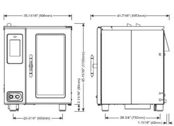
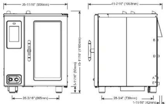
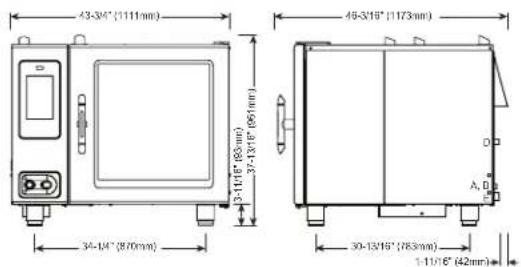
| DIMENSIONS: H x W x D | |||
| EXTERIOR:45-11/16" x 35-11/16" x 41-7/16" (1160mm x 906mm x 1053mm) | |||
| EXTERIOR WITH RECESSED DOOR:45-11/16" x 40-11/16" x 41-7/16" (1160mm x 1033mm x 1053mm) | |||
| INTERIOR:31-1/2" x 16-1/4" x 28-1/16" (800mm x 411mm x 712mm) | |||
| WATER QUALITY STANDARDS | |||
| It is the sole responsibility of the owner/operator/purchaser of this equipment to verify that the incoming water supply is comprehensively tested and if required, a means of "water treatment" provided that would meet compliance requirements with the published water quality standards shown below.Non-compliance with these minimum standards will potentially damage this equipment and/or components and void the original equipment manufacturer's warranty. Alto-Shaam recommends using OptiPure® [www.optipurewater.com] products to properly treat your water.Contaminant Inlet Water RequirementsFree Chlorine Less than 0.1 ppm (mg/L)Hardness 30-70 ppmChloride Less than 30 ppm (mg/L)pH 7.0 to 8.5Silica Less than 12 ppm (mg/L)Total Dissolved Solids (tds) 50-125 ppm | |||
| L3, N, G | |||
| 16.2 – 18.9 | 25 | 8 | L1, L2, L3, G |
* ELECTRICAL SERVICE CHARGE APPLIES
| WEIGHT | SHIP DIMENSIONS | PAN CAPACITY | |||||
| NET | 625 lbs est | 283 kg | (L x W x H) 45" x 45" x 65** | FULL-SIZE: | 20" x 12" x 2-1/2" | Eleven (11) | PRODUCT MAXIMUM: 120 lb (54 kg) |
| SHIP | 650 lbs* | 295 kg* | (1143 x 1143 x 1651mm)* | GN 1/1: | 530 x 325 x 65mm | Eleven (11) | VOLUME MAXIMUM: 75 quarts (95 liters) |
| *DOMESTIC GROUND SHIPPING INFORMATION, CONTACT FACTORY FOR EXPORT WEIGHT AND DIMENSIONS. | **HALF-SIZE SHEET: | 18" x 13" x 1" | Eleven (11) | **ON WIRE SHELVES ONLY, ADDITIONAL WIRE SHELVES REQUIRED FOR MAXIMUM CAPACITY | |||
text_image
25-11/16" (900mm) 41-7/16" (1053mm) 28-3/16" (905mm) 28-3/4" (733mm) 1-11/16" (42mm)A= UNTREATED WATER
B= TREATED WATER
C=ELECTRICAL
D=GAS
E= WATER DRAIN
text_image
3-5/16" (84mm) 4-5/16" (109mm) 6-13/15" (171mm) 6-15/15" (176mm) 5-7/8" (149mm) 9-10/8" (200mm) 2'-1'-2" (545mm) 30'-12" (775mm)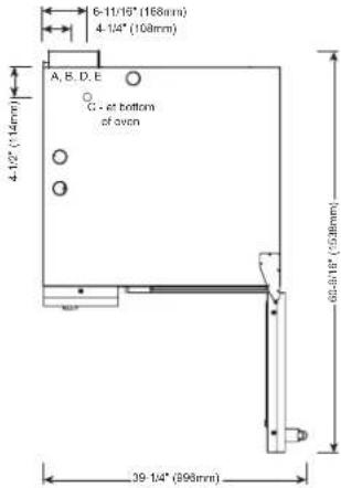
text_image
6-11/19" (168mm) 4-1/4" (108mm) A, B, D, E C - at bottom of oven 4-1/2" (114mm) 39-1/4" (995mm) 62-9-19" (928mm)
COOKING APPLIANCE
180m

ANSI/NSF 4


IP X5

DIMENSIONS: H x W x D
EXTERIOR
| 45-11/16" x 35-11/16" x 41-7/16" (1160mm x 906mm x 1053mm) |
EXTERIOR WITH RECESSED DOOR:
| 45-11/16" x 40-11/16" x 41-7/16" (1160mm x 1033mm x 1053mm) |
INTERIOR:
| 31-1/2" x 16-1/4" x 28-1/16" (800mm x 411mm x 712mm) |
WATER QUALITY STANDARDS
| TWO (2) COLD WATER INLETS - DRINKING QUALITYONE (1) TREATED WATER INLET: 3/4" NPT* * Can manifold off ofONE (1) UNTREATED WATER INLET: 3/4" NPT* one 3/4" lineLINE PRESSURE: 30 psi minimum dynamic and 90 psi maximum static (200 to 600 kPa)WATER DRAIN: 1-1/2" (40mm) CONNECTION WITH A VERTICAL VENT TO EXTEND ABOVE THE EXHAUST VENT.MATERIALS MUST WITHSTAND TEMPERATURES UP TO 200°F (93°C). | It is the sole responsibility of the owner/operator/purchaser of this equipment to verify that the incoming water supply is comprehensively tested and if required, a means of "water treatment" provided that would meet compliance requirements with the published water quality standards shown below.Non-compliance with these minimum standards will potentially damage this equipment and/or components and void the original equipment manufacturer's warranty. Alto-Shaam recommends using OptiPure® [www.optipurewater.com] products to properly treat your water.Contaminant Inlet Water RequirementsFree Chlorine Less than 0.1 ppm (mg/L)Hardness 30-70 ppmChloride Less than 30 ppm (mg/L)pH 7.0 to 8.5Silica Less than 12 ppm (mg/L)Total Dissolved Solids (tds) 50-125 ppm | |
| CLEARANCE REQUIREMENTS | ||
| LEFT: 0" (0mm) | 18" (457mm) RECOMMENDED SERVICE ACCESS | |
| RIGHT: 0" (0mm) NON-COMBUSTIBLE SURFACES | 2" (51mm) DOOR SWING OR COMBUSTIBLE SURFACES | |
| TOP: 20" (508mm) FOR AIR MOVEMENT | ||
| BACK: 4" (102mm)4-5/16" (109mm) OPTIONAL PLUMBING KIT | BOTTOM: 5-1/8" (130mm)FOR LEGS, AIR INTAKE | |
| INSTALLATION REQUIREMENTS | ||
| • Oven must be installed level. • Hood installation is required.• Water supply shut-off valve and back-flow preventer when required by local code. | ||
GAS REQUIREMENTS (GAS TYPE MUST BE SPECIFIED ON ORDER)
HOOK-UP: 3/4" NPT
| RATED THERMAL LOAD CONNECTED PRESSURE | ||||||||||||
| NORTH AMERICA INTERNATIONAL NORTH AMERICA INTERNATIONAL | ||||||||||||
| Natural Gas/Propane G20, G25, G31 Natural Gas Propane | G20 20mbarG25 20mbarG31 30mbar | |||||||||||
| Gross Heating Value (HHV) Net Heating Value (LHV) Minimum: 5.5" W.C. dynamic Minimum: 9" W.C. dynamic80,000 Btu / hr | 21.0 kW | Maximum: 14" W.C. static | Maximum: 14" W.C. static | |||||||||
| ELECTRICAL - CTP10-10G (DEDICATED CIRCUIT REQUIRED) | WITH COMBISMOKER® OPTION | |||||||||||
| VOLTAGE | PH | HZ | AWG | CONNECTIONno cord, no plug | AMPS | BREAKER | kW | CONNECTIONno cord, no plug | AMPS | BREAKER | kW | |
| ∅∅ | 120 | 1 | 60 | 14 | L1, N, G | 6.8 | 20 | .84 | L1, N, G | 12.0 | 20 | 1.46 |
| ∅∅ | 208 – 240 | 1+ | 50/60 | 14 | L1, L2/N, G | 4.8 – 4.2 | 15 | 1.0 | L1, L2/N, G | 7.3 – 7.1 | 15 | 1.5 – 1.7 |
| ∅∅ | 208 – 240 | 3 | 50/60 | 14 | L1, L2, L3, G | 4.8 – 4.2 | 15 | 1.0 | L1, L2, L3, G | 7.3 – 7.1 | 15 | 1.5 – 1.7 |
| ∅∅ | 380 – 415 | 3 | 50/60 | 14 | L1, L2, L3, N, G | 4.6 – 4.2 | 15 | 1.0 | L1, L2, L3, N, G | 7.2 – 7.1 | 15 | 1.6 – 1.7 |
NORTH AMERICA VOLTAGE CHOICE GROUND FAULT OR RESIDUAL CURRENT PROTECTION DEVICE MUST ACCOMMODATE A LEAKAGE CURRENT OF 20mA INTERNATIONAL VOLTAGE CHOICE ELECTRICAL SERVICE CHARGE APPLIES
| WEIGHT | PAN CAPACITY | STANDARD MODEL | WITH COMBISMOKER® OPTION | ||
| NET | 625 lbs est | 283 kg | FULL-SIZE: 20" x 12" x 2-1/2"GN 1/1: 530 x 325 x 65mm**HALF-SIZE SHEET: 18" x 13" x 1* | Eleven (11)Eleven (11)Eleven (11) | Ten (10)Ten (10)Eleven (11) |
| SHIP | 695 lbs* | 315 kg* | |||
| SHIP DIMENSIONS | PRODUCT CAPACITY | ||||
| (L x W x H) 56" x 45" x 65"(1422mm x 1143mm x 1651mm)* | PRODUCT MAXIMUM | 120 lb (54 kg) | |||
| VOLUME MAXIMUM | 75 quarts (95 liters) | ||||
| *DOMESTIC GROUND SHIPPING INFORMATION. CONTACT FACTORY FOR EXPORT WEIGHT AND DIMENSIONS. | **ON WIRE SHELVES ONLY. ADDITIONAL WIRE SHELVES REQUIRED FOR MAXIMUM CAPACITY | ||||
text_image
35-11/16" (906mm) 41-7/16" (1063mm) 28-3/16" (865mm) 28-3/4" (730mm) 1-11/16" (42mm)A= UNTREATED WATER
B-TREATED WA
C-ELECTRICAL
U= GAS
E=WATER DRAL
text_image
3-5/16" (84mm) 4-5/16" (109mm) 6-13/15" (171mm) 6-15/10" (178mm) 2-1/2" (545mm) 3/2-1/2" (775mm) 5-7/8" (1480mm) 9-11/8" (230mm)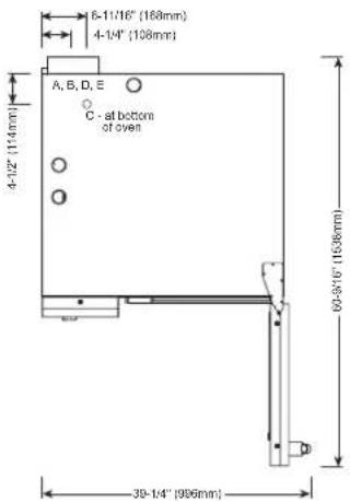
text_image
6-11/16" (168mm) 4-14" (108mm) A, B, D, E C - at bottom of oven 4-12" (114mm) 39-14" (996mm) 60-9/16" (1636mm)

CE EAC IP X5

WATER REQUIREMENTS
TWO (2) COLD WATER INLETS - DRINKING QUALITY
| ONE (1) TREATED WATER INLET: 3/4" NPT* | * Can manifold off of |
| ONE (1) UNTREATED WATER INLET: 3/4" NPT* | one 3/4" line |
| LINE PRESSURE: 30 psi minimum dynamic and 90 psi maximum static (200 to 600 kPa) | |
| WATER DRAIN: 1-1/2" (40mm) CONNECTION WITH A VERTICAL VENT TO EXTEND ABOVE THE EXHAUST VENT. MATERIALS MUST WITHSTAND TEMPERATURES UP TO 200°F (93°C). | |
CLEARANCE REQUIREMENTS
| LEFT: 0" (0mm) | 18" (457mm) RECOMMENDED SERVICE ACCESS |
| RIGHT: 0" (0mm) NON-COMBUSTIBLE SURFACES | 2" (51mm) DOOR SWING OR COMBUSTIBLE SURFACES |
| TOP: 20" (508mm) FOR AIR MOVEMENT | |
| BACK: 4" (102mm)4-5/16" (109mm) OPTIONAL PLUMBING KIT | BOTTOM: 5-1/8" (130mm)FOR LEGS, AIR INTAKE |
INSTALLATION REQUIREMENTS
| • Oven must be installed level. | • Hood installation is required. |
| • Water supply shut-off valve and back-flow preventer when required by local code. | |
DIMENSIONS: H x W x D
| EXTERIOR: |
| 45-11/16" x 35-11/16" x 41-7/16" (1160mm x 906mm x 1053mm) |
EXTERIOR WITH RECESSED DOOR:
| 45-11/16" x 40-11/16" x 41-7/16" (1160mm x 1033mm x 1053mm) |
INTERIOR:
| 31-1/2" x 16-1/4" x 28-1/16" (800mm x 411mm x 712mm) |
WATER QUALITY STANDARDS
| It is the sole responsibility of the owner/operator/purchaser of this equipment to verify that the incoming water supply is comprehensively tested and if required, a means of "water treatment" provided that would meet compliance requirements with the published water quality standards shown below.Non-compliance with these minimum standards will potentially damage this equipment and/or components and void the original equipment manufacturer's warranty. Alto-Shaam recommends using OptiPure® [www.optipurewater.com] products to properly treat your water. |
Contaminant Inlet Water Requirements
| Free Chlorine | Less than 0.1 ppm (mg/L) |
| Hardness | 30-70 ppm |
| Chloride | Less than 30 ppm (mg/L) |
| pH | 7.0 to 8.5 |
| Silica | Less than 12 ppm (mg/L) |
| ed Solids (tds) | 50-125 ppm |
GAS REQUIREMENTS (GAS TYPE MUST BE SPECIFIED ON ORDER)
| HOOK-UP: 3/4" NPT | ||||
| RATED THERMAL LOAD CONNECTED PRESSURE | ||||
| NORTH AMERICA INTERNATIONAL NORTH AMERICA INTERNATIONAL | ||||
| Natural Gas/Propane G20, G25, G31 Natural Gas Propane | G20 20mbar | |||
| Gross Heating Value (HHV) Net70,000 Btu / hr | Heating Value (LHV) Minimum: 5.5" W.C. dynamic Minimum: 9" W.C. dynamicMaximum: 14" W.C. static | Maximum: 14" W.C. static | Maximum: 14" W.C. static | G25 20mbarG31 30mbar |
ELECTRICAL - CTC10-10G (DEDICATED CIRCUIT REQUIRED)
| VOLTAGE | PH | HZ | AWG | CONNECTION | AMPS | BREAKER | kW | |
| ∞ | 120 | 1 | 60 | 14 | L1, N, G - no cord, no plug | 7 | 20 | .84 |
| ∞ | 208 – 240 | 3 | 50/60 | 14 | L1, L2, L3, G - no cord, no plug | 4.8 – 4.2 | 15 | 1.0 |
| ∞ | 380 – 415 | 3 | 50/60 | 14 | L1, L2, L3, N, G - no cord, no plug | 4.6 – 4.2 | 15 | 1.0 |
NORTH AMERICA VOLTAGE CHOICE GROUND FAULT OR RESIDUAL CURRENT PROTECTION DEVICE MUST ACCOMMODATE A LEAKAGE CURRENT OF 20mA INTERNATIONAL VOLTAGE CHOICE
| WEIGHT | SHIP DIMENSIONS | PAN CAPACITY | ||||
| NET | 625 lbs est 283 kg | (L x W x H) 56" x 45" x 65"* | FULL-SIZE: | 20" x 12" x 2-1/2" | Eleven (11) | PRODUCT MAXIMUM: 120 lb (54 kg) |
| SHIP | 695 lbs* 315 kg* (1422) | x 1143 x 1651mm)* | GN 1/1: | 530 x 325 x 65mm | Eleven (11) | VOLUME MAXIMUM: 75 quarts (95 liters) |
| *DOMESTIC GROUND SHIPPING INFORMATION. CONTACT FACTORY FOR EXPORT WEIGHT AND DIMENSIONS. | **HALF-SIZE SHEET: | 18" x 13" x 1" | Eleven (11) | **ON WIRE SHELVES ONLY, ADDITIONAL WIRE SHELVES REQUIRED FOR MAXIMUM CAPACITY | ||
text_image
43-3/4" (1111mm) 37-13/16" (981mm) 46-3/16" (1173mm) A= UNTREATED WATER B= TREATED WATER C= ELECTRICAL D= WATER DRAIN E= OPTIONAL ELECTRICAL 34-1/4" (870mm) 30-13/16" (783mm) 1-11/16" (42mm) (E) 2" (50mm) (A) 2-5/16" (58mm) (B) 3-3/16" (81mm) 3-11/16" (63mm) 5-7/8" (149mm) 7-7/8" (200mm) 11-3/4" (298mm) 4-1/2" (114mm) 6-11/16" (168mm) 4-1/4" (108mm) A, B, D C - at bottom of even 73-5/16" (1863mm) 47-7/16" (1205mm)


CE EAC IP X5
| WATER REQUIREMENTS | WATER QUALITY STANDARDS | ||
| TWO (2) COLD WATER INLETS - DRINKING QUALITYONE (1) TREATED WATER INLET: 3/4" NPT* * Can manifold off ofONE (1) UNTREATED WATER INLET: 3/4" NPT* one 3/4" lineLINE PRESSURE: 30 psi minimum dynamic and 90 psi maximum static (200 to 600 kPa)WATER DRAIN: 1-1/2" (40mm) CONNECTION WITH A VERTICAL VENT TO EXTEND ABOVE THE EXHAUST VENT.MATERIALS MUST WITHSTAND TEMPERATURES UP TO 200°F (93°C). | It is the sole responsibility of the owner/operator/purchaser of this equipment to verify that the incoming water supply is comprehensively tested and if required, a means of "water treatment" provided that would meet compliance requirements with the published water quality standards shown below.Non-compliance with these minimum standards will potentially damage this equipment and/or components and void the original equipment manufacturer's warranty. Alto-Shaam recommends using OptiPure® [www.optipurewater.com] products to properly treat your water.Contaminant Inlet Water RequirementsFree Chlorine Less than 0.1 ppm (mg/L)Hardness 30-70 ppmChloride Less than 30 ppm (mg/L)pH 7.0 to 8.5Silica Less than 12 ppm (mg/L)Total Dissolved Solids (tds) 50-125 ppm | ||
| CLEARANCE REQUIREMENTS | |||
| LEFT: 0" (0mm) | 18" (457mm) RECOMMENDED SERVICE ACCESS | ||
| RIGHT: 0" (0mm) NON-COMBUSTIBLE SURFACES | 2" (51mm) DOOR SWING OR COMBUSTIBLE SURFACES | ||
| TOP: 20" (508mm) FOR AIR MOVEMENT | |||
| BACK: 4" (102mm)4-5/16" (109mm) OPTIONAL PLUMBING KIT | BOTTOM: 5-1/8" (130mm)FOR LEGS, AIR INTAKE | ||
| INSTALLATION REQUIREMENTS | |||
| • Oven must be installed level. • Hood installation is required.• Water supply shut-off valve and back-flow preventer when required by local code. | |||
| ELECTRICAL - CTP7-20E (NO CORD, NO PLUG, DEDICATED CIRCUIT REQUIRED) | WITH COMBISMOKER® OPTION | ||||||||||||||||
| ECO STANDARD | **PROpowerTM OPTION | ECO STANDARD | **PROpowerTM OPTION | ||||||||||||||
| VOLTAGE | PH | HZ | AWG | CONNECTION | AMPS | kW | BREAKER | AMPS | kW | BREAKER | AMPS | kW | BREAKER | AMPS | kW | BREAKER | |
| 208 – 240 | 1* | 50/60 | 1 – 1/0 | L1, L2/N, G | 79.1 – 91.3 | 16.5 – 21.9 | 80 – 100 | 92.1 – 106.3 | 19.2 – 25.5 | 100 – 110 | 81.6 – 94.1 | 17 – 22.6 | 90 – 100 | 94.6 – 109.1 | 19.7 – 26.2 | 100 – 110 | |
| 208 – 240 | 3 | 50/60 | 4 – 3 | L1, L2, L3, G | 45.7 – 52.7 | 16.5 – 21.9 | 50 – 60 | 58.7 – 67.7 | 19.2 – 25.5 | 60 – 70 | 48.2 – 55.6 | 17 – 22.6 | 50 – 60 | 61.2 – 70.6 | 19.7 – 26.2 | 70 | |
| 380 – 415 | 3 | 50/60 | 6 – 4 | L1, L2, L3, N, G | 28 – 30.4 | 18.7 – 21.9 | 32 | 41.7 – 45.4 | 21.4 – 25.5 | 63 | 30.6 – 33.3 | 19.3 – 22.6 | 32 – 63 | 44.4 – 48.3 | 22 – 26.2 | 63 | |
| 440 – 480 | 3* | 50/60 | 8 | L1, L2, L3, G | 20.6 – 22.4 | 15.7 – 18.7 | 25 | 26.5 – 28.8 | 18.3 – 21.8 | 30 – 35 | 21.9 – 23.8 | 16.2 – 19.2 | 30 | 27.3 – 30.0 | 18.8 – 22.3 | 30 – 35 | |
*ELECTRICAL SERVICE CHARGE APPLIES
*NO-COST OPTION ON ELECTRIC MODELS
| WEIGHT | PAN CAPACITY | STANDARD MODEL | WITH COMBISMOKER® OPTION | |||
| NET | 680 lbs EST | 308 kg | FULL-SIZE: | 20" x 12" x 2-1/2" | Sixteen (16) | Fifteen (15) |
| GN 1/1: | 530 x 325 x 65mm | Sixteen (16) | Fifteen (15) | |||
| SHIP | 727 lbs* | 330 kg* | GN 2/1: | 650 x 530 x 65mm | Eight (8) | Seven (7) |
| **FULL-SIZE SHEET: | 18" x 26" x 1" | Eight (8) | Eight (8) | |||
| SHIP DIMENSIONS | PRODUCT CAPACITY | |||||
| (L x W x H) 56" x 49" x 65**(1422mm x 1245mm x 1651mm)* | PRODUCT MAXIMUM | 168 lb (76 kg) | ||||
| VOLUME MAXIMUM | 105 quarts (133 liters) | |||||
| *DOMESTIC GROUND SHIPPING INFORMATION. CONTACT FACTORY FOR EXPORT WEIGHT AND DIMENSIONS. | **ON WIRE SHELVES ONLY. ADDITIONAL WIRE SHELVES REQUIRED FOR MAXIMUM CAPACITY | |||||
MN-35947 • Rev 10 • 06/16 • COMBITHERM CT PROFORMANCE AND CT CLASSIC SERIES • INSTALLATION MANUAL • 17
text_image
43-3/4" (1111mm) 37-13/16" (961mm) 46-3/16" (1173mm) 34-1/4" (870mm) 30-13/16" (783mm) 1-11/16" (42mm) A. B E B A (A) 2-5/16" (58mm) (D) 3-3/16" (81mm) (B) 4-7/8" (124mm) (E) 2" (50mm) (3-11/16" (93mm) 5-7/8" (149mm) 7-7/8" (200mm) 11-3/4" (298mm) 47-7/16" (1205mm) A= UNTREATED WATER B= TREATED WATER C= ELECTRICAL D= WATER DRAIN E= OPTIONAL ELECTRICAL 6-11/16" (168mm) 4-1/4" (108mm) A, B, D C - at bottom of oven 73 5/16" (1863mm)

CE EAC IP X5
| WATER REQUIREMENTS | WATER QUALITY STANDARDS | ||||||
| TWO (2) COLD WATER INLETS - DRINKING QUALITYONE (1) TREATED WATER INLET: 3/4" NPT* * Can manifold off ofONE (1) UNTREATED WATER INLET: 3/4" NPT* one 3/4" lineLINE PRESSURE: 30 psi minimum dynamic and 90 psi maximum static (200 to 600 kPa)WATER DRAIN: 1-1/2" (40mm) CONNECTION WITH A VERTICAL VENT TO EXTEND ABOVE THE EXHAUST VENT.MATERIALS MUST WITHSTAND TEMPERATURES UP TO 200°F (93°C). | It is the sole responsibility of the owner/operator/purchaser of this equipment to verify that the incoming water supply is comprehensively tested and if required, a means of "water treatment" provided that would meet compliance requirements with the published water quality standards shown below.Non-compliance with these minimum standards will potentially damage this equipment and/or components and void the original equipment manufacturer's warranty. Alto-Shaam recommends using OptiPure® [www.optipurewater.com] products to properly treat your water.Contaminant Inlet Water RequirementsFree Chlorine Less than 0.1 ppm (mg/L)Hardness 30-70 ppmChloride Less than 30 ppm (mg/L)pH 7.0 to 8.5Silica Less than 12 ppm (mg/L)Total Dissolved Solids (tds) 50-125 ppm | ||||||
| CLEARANCE REQUIREMENTS | |||||||
| LEFT: 0" (0mm) | 18" (457mm) RECOMMENDED SERVICE ACCESS | ||||||
| RIGHT: 0" (0mm) NON-COMBUSTIBLE SURFACES | 2" (51mm) DOOR SWING OR COMBUSTIBLE SURFACES | ||||||
| TOP: 20" (508mm) FOR AIR MOVEMENT | |||||||
| BACK: 4" (102mm)4-5/16" (109mm) OPTIONAL PLUMBING KIT | BOTTOM: 5-1/8" (130mm)FOR LEGS, AIR INTAKE | ||||||
| INSTALLATION REQUIREMENTS | |||||||
| · Oven must be installed level. · Hood installation is required.· Water supply shut-off valve and back-flow preventer when required by local code. | |||||||
| ELECTRICAL (NO CORD, NO PLUG, DEDICATED CIRCUIT REQUIRED) | |||||||
| MODEL VOLTAGE PH HZ AMPS KW BREAKER AWG CONNECTION | |||||||
| CTC7-20E | 208-240 3 50/60 45.7-52.7 16.5-21.9 50-60 4-3 L1, L2, L3, G | ||||||
| 380-415 3 50/60 28-30.4 18.7-21.9 32 6-4 L1, L2, L3, N, G | |||||||
| 440-480 3* 50/60 20.6-22.4 15.7-18.7 25 8 L1, L2, L3, G | |||||||
*ELECTRICAL SERVICE CHARGE APPLIES
| WEIGHT | SHIP DIMENSIONS PAN CAPACITY | ||||||
| NET | 680 lbs est | 308 kg | (L x W x H) 56" x 49" x 65"* | FULL-SIZE: | 20" x 12" x 2-1/2" | Sixteen (16) | PRODUCT MAXIMUM: 168 lb (76 kg) |
| SHIP | 727 lbs* | 330 kg* | (1422 x 1245 x 1651mm)* | GN 1/1: | 530 x 325 x 65mm | Sixteen (16) | VOLUME MAXIMUM: 105 quarts (133 liters) |
| *DOMESTIC GROUND SHIPPING INFORMATION, CONTACT FACTORY FOR EXPORT WEIGHT AND DIMENSIONS. | GN 2/1: | 650 x 530 x 65mm | Eight (8) | **ON WIRE SHELVES ONLY, ADDITIONAL WIRE SHELVES REQUIRED FOR MAXIMUM CAPACITY | |||
| **FULL-SIZE SHEET: | 18" x 26" x 1" | Eight (8) | |||||

text_image
ALTO-SHAAM. CTPROformance™CTP7-20G
GAS BOILER-FREE
text_image
43-34" (1111mm) 34-10" (870mm) 45-316" (1173mm) 3-11/16" (89mm) 37-13/16" (96mm) 30-13/16" (78.3mm) 1-11/16" (42mm)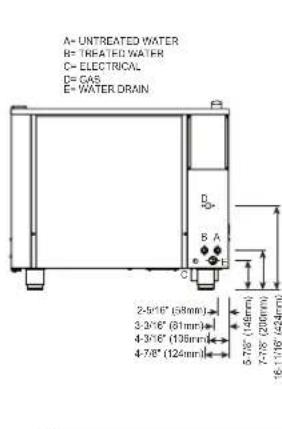
text_image
A= UNTREATED WATER B= TREATED WATER C= ELECTRICAL D= GAS E= WATER.DRAIN 2-5/16" (58mm) 3-3/16" (81mm) 4-3/16" (108mm) 4-7/8" (124mm) 5-7/8" (149mm) 7-7/8" (200mm) 16-11/16" (424mm)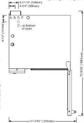
text_image
8-11'16" (168mm) 4-14" (108mm) A, B, D, E C - at bottom of oven 73.5'16" (965mm) 47-7'18" (1205mm)


CE EAC IP X5
WATER REQUIREMENTS
| TWO (2) COLD WATER INLETS - DRINKING QUALITYONE (1) TREATED WATER INLET: 3/4" NPT* * Can manifold off ofONE (1) UNTREATED WATER INLET: 3/4" NPT* one 3/4" lineLINE PRESSURE: 30 psi minimum dynamic and 90 psi maximum static (200 to 600 kPa)WATER DRAIN: 1-1/2" (40mm) CONNECTION WITH A VERTICAL VENT TO EXTEND ABOVE THE EXHAUST VENT.MATERIALS MUST WITHSTAND TEMPERATURES UP TO 200°F (93°C). | |
| CLEARANCE REQUIREMENTS | |
| LEFT: 0" (0mm) | 18" (457mm) RECOMMENDED SERVICE ACCESS |
| RIGHT: 0" (0mm) NON-COMBUSTIBLE SURFACES | 2" (51mm) DOOR SWING ORCOMBUSTIBLE SURFACES |
| TOP: 20" (508mm) FOR AIR MOVEMENT | |
| BACK: 4" (102mm)4-5/16" (109mm) OPTIONAL PLUMBING KIT | BOTTOM: 5-1/8" (130mm)FOR LEGS, AIR INTAKE |
| INSTALLATION REQUIREMENTS | |
| • Oven must be installed level. • Hood installation is required.• Water supply shut-off valve and back-flow preventer when required by local code. | |
GAS REQUIREMENTS (GAS TYPE MUST BE SPECIFIED ON ORDER)
| HOOK-UP: 3/4" NPT | ||||||||||||
| RATED THERMAL LOAD CONNECTED PRESSURE | ||||||||||||
| NORTH AMERICA INTERNATIONAL NORTH AMERICA INTERNATIONAL | ||||||||||||
| Natural Gas/Propane G20, G25, G31 Natural Gas Propane | G20 20mbar | |||||||||||
| Gross Heating Value (HHV) Net Heating Value (LHV) Minimum: 5.5" W.C. dynamic Minimum: 9" W.C. dynamic | G25 20mbar | |||||||||||
| 98,000 Btu / hr 26.5 kW Maximum: 14" W.C. static Maximum: 14" W.C. static G31 30mbar | ||||||||||||
| ELECTRICAL - CTP7-20G (DEDICATED CIRCUIT REQUIRED) | WITH COMBISMOKER® OPTION | |||||||||||
| VOLTAGE | PH | HZ | AWG | CONNECTION no cord, no plug | AMPS | BREAKER | kW | CONNECTION no cord, no plug | AMPS | BREAKER | kW | |
| →→ | 120 | 1 | 60 | 14 | L1, N, G | 6.8 | 20 | .84 | L1, N, G | 12.0 | 20 | 1.46 |
| →→ | 208 – 240 | 1' | 50/60 | 14 | L1, L2/N, G | 4.8 – 4.2 | 15 | 1.0 | L1, L2/N, G | 7.3 – 7.1 | 15 | 1.5 – 1.7 |
| →→ | 208 – 240 | 3 | 50/60 | 14 | L1, L2, L3, G | 4.8 – 4.2 | 15 | 1.0 | L1, L2, L3, G | 7.3 – 7.1 | 15 | 1.5 – 1.7 |
| → | 380 – 415 | 3 | 50/60 | 14 | L1, L2, L3, N, G | 4.6 – 4.2 | 15 | 1.0 | L1, L2, L3, N, G | 7.2 – 7.1 | 15 | 1.6 – 1.7 |
NORTH AMERICA VOLTAGE CHOICE GROUND FAULT OR RESIDUAL CURRENT PROTECTION DEVICE MUST ACCOMMODATE A LEAKAGE CURRENT OF 20mA INTERNATIONAL VOLTAGE CHOICE ELECTRICAL SERVICE CHARGE APPLIES
| WEIGHT | PAN CAPACITY | STANDARD MODEL | WITH COMBISMOKER® OPTION | |||
| NET | 660 lbs EST | 300 kg | FULL-SIZE: | 20" x 12" x 2-1/2" | Sixteen (16) | Fifteen (15) |
| GN 1/1: | 530 x 325 x 65mm | Sixteen (16) | Fifteen (15) | |||
| SHIP | 680 lbs* | 308 kg* | GN 2/1: | 650 x 530 x 65mm | Eight (8) | Seven (7) |
| **FULL-SIZE SHEET: | 18" x 26" x 1" | Eight (8) | Eight (8) | |||
| SHIP DIMENSIONS | PRODUCT CAPACITY | |||||
| (L x W x H) 56" x 48" x 51**(1422mm x 1219mm x 1295mm)* | PRODUCT MAXIMUM | 168 lb (76 kg) | ||||
| VOLUME MAXIMUM | 105 quarts (133 liters) | |||||
| *DOMESTIC GROUND SHIPPING INFORMATION. CONTACT FACTORY FOR EXPORT WEIGHT AND DIMENSIONS. | **ON WIRE SHELVES ONLY, ADDITIONAL WIRE SHELVES REQUIRED FOR MAXIMUM CAPACITY | |||||
text_image
43-3/4" (1111mm) 34-1/4" (870mm) 3-1/16" (50mm) 3-2/16" (46mm) 48-3/19" (1173mm) 30-13/18" (783mm) 1-1/18" (42mm) A= UNTREATED WATER B= TREATED WATER C= ELECTRICAL D= GAS E= WATER DRAIN 2-5/16" (58mm) 3-3/16" (61mm) 4-3/16" (108mm) 4-7/8" (124mm) 5-7/8" (145mm) 7-7/8" (200mm) 16-11/16" (42mm) 8-11/16" (160mm) 4-1/4" (108mm) A, B, C, D, E C - at bottom of oven 73.5/19" (180mm) 47-7/16" (1205mm)


CE EAC IP X5
| WATER REQUIREMENTS | WATER QUALITY STANDARDS | ||||||||
| TWO (2) COLD WATER INLETS - DRINKING QUALITYONE (1) TREATED WATER INLET: 3/4" NPT* * Can manifold off ofONE (1) UNTREATED WATER INLET: 3/4" NPT* one 3/4" lineLINE PRESSURE: 30 psi minimum dynamic and 90 psi maximum static (200 to 600 kPa)WATER DRAIN: 1-1/2" (40mm) CONNECTION WITH A VERTICAL VENT TO EXTEND ABOVE THEEXHAUST VENT.MATERIALS MUST WITHSTAND TEMPERATURES UP TO 200°F (93°C). | It is the sole responsibility of the owner/operator/purchaser of this equipment to verify that the incoming water supply is comprehensively tested and if required, a means of "water treatment" provided that would meet compliance requirements with the published water quality standards shown below.Non-compliance with these minimum standards will potentially damage this equipment and/or components and void the original equipment manufacturer's warranty. Alto-Shaam recommends using OptiPure® [www.optipurewater.com] products to properly treat your water.Contaminant Inlet Water RequirementsFree Chlorine Less than 0.1 ppm (mg/L)Hardness 30-70 ppmChloride Less than 30 ppm (mg/L)pH 7.0 to 8.5Silica Less than 12 ppm (mg/L)Total Dissolved Solids (tds) 50-125 ppm | ||||||||
| CLEARANCE REQUIREMENTS | |||||||||
| LEFT: 0" (0mm) | 18" (457mm) RECOMMENDED SERVICE ACCESS | ||||||||
| RIGHT: 0" (0mm) NON-COMBUSTIBLE SURFACES | 2" (51mm) DOOR SWING OR COMBUSTIBLE SURFACES | ||||||||
| TOP: 20" (508mm) FOR AIR MOVEMENT | |||||||||
| BACK: 4" (102mm)4-5/16" (109mm) OPTIONAL PLUMBING KIT | BOTTOM: 5-1/8" (130mm)FOR LEGS, AIR INTAKE | ||||||||
| INSTALLATION REQUIREMENTS | |||||||||
| ·Oven must be installed level. ·Hood installation is required.·Water supply shut-off valve and back-flow preventer when required by local code. | |||||||||
| GAS REQUIREMENTS (GAS TYPE MUST BE SPECIFIED ON ORDER) | |||||||||
| HOOK-UP: 3/4" NPT | |||||||||
| RATED THERMAL LOAD CONNECTED PRESSURE | |||||||||
| NORTH AMERICA INTERNATIONAL NORTH AMERICA INTERNATIONAL | |||||||||
| Natural Gas/Propane G20, G25, G31 Natural Gas Propane | G20 20mbar | ||||||||
| Gross Heating Value (HHV) Net85,000 Btu / hr | Heating Value (LHV) Minimum: 5.5" W22.5 kW | C. dynamic Minimum: 9" W.C. dynamicMaximum: 14" W.C. static | Maximum: 14" W.C. static | G25 20mbarG31 30mbar | |||||
| ELECTRICAL - CTC7-20G (DEDICATED CIRCUIT REQUIRED) | |||||||||
| VOLTAGE | PH | HZ | AWG | CONNECTION | AMPS | BREAKER | kW | ||
| ∞ | 120 | 1 | 60 | 14 | L1, N, G - no cord, no plug | 7.0 | 20 | .84 | |
| ∞ | 208 – 240 | 3 | 50/60 | 14 | L1, L2, L3, G - no cord, no plug | 4.8 – 4.2 | 15 | 1.0 | |
| ∞ | 380 – 415 | 3 | 50/60 | 14 | L1, L2, L3, N, G - no cord, no plug | 4.6 – 4.2 | 15 | 1.0 | |
NORTH AMERICA VOLTAGE CHOICE ✉️ GROUND FAULT OR RESIDUAL CURRENT PROTECTION DEVICE MUST ACCOMMODATE A LEAKAGE CURRENT OF 20mA ✉️ INTERNATIONAL VOLTAGE CHOICE
| WEIGHT | SHIP DIMENSIONS | PAN CAPACITY | ||||
| NET | 660 lbs est 300 kg | (L x W x H) 56" x 48" x 51** | FULL-SIZE: 20" x 12" x 2-1/2" Sixteen (16) | PRODUCT MAXIMUM: 168 lb (76 kg) | ||
| SHIP | 680 lbs* 308 kg* | (1422 x 1219 x 1295mm)* | GN 1/1: | 530 x 325 x 65mm | Sixteen (16) | VOLUME MAXIMUM: 105 quarts (133 liters) |
| *DOMESTIC GROUND SHIPPING INFORMATION. CONTACT FACTORY FOR EXPORT WEIGHT AND DIMENSIONS. | GN 2/1: | 650 x 530 x 65mm | Eight (8) | **ON WIRE SHELVES ONLY, ADDITIONAL WIRE SHELVES REQUIRED FOR MAXIMUM CAPACITY | ||
| **FULL-SIZE SHEET: | 18" x 26" x 1" | Eight (8) | ||||
ELECTRIC BOILER

text_image
43-3/4" (111mm) 45-11/16" (1150mm) 34-1/4" (870mm) 4-5/8" (117mm)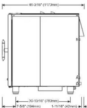
text_image
46-3/16" (1173mm) 30-13/16" (783mm) 7.5/8" (194mm) 1-11/16" (42mm)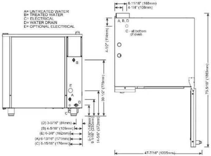
text_image
A= UNTREATED WATER B= TREATED WATER C= ELECTRICAL D= WATER DRAIN E= OPTIONAL ELECTRICAL 6-11/16" (168mm) 4-1/4" (108mm) A, B, D C - at bottom of oven 73.5/16" (188mm) 47-7/16" (1205mm) (D) 3-5/16" (84mm) (B) 4-5/16" (109mm) (E) 6-3/8" (162mm) (A) 6-13/16" (171mm) (C) 6-15/16" (178mm) 30 1/2" (775mm) 5-7/8" (149mm) 9-1/6" (225mm) 14-5/6" (372mm)

CE EAC IP X5
| TWO (2) COLD WATER INLETS - DRINKING QUALITYONE (1) TREATED WATER INLET: 3/4" NPT* Can manifold off ofONE (1) UNTREATED WATER INLET: 3/4" NPT* one 3/4" lineLINE PRESSURE: 30 psi minimum dynamic and 90 psi maximum static (200 to 600 kPa)WATER DRAIN: 1-1/2" (40mm) CONNECTION WITH A VERTICAL VENT TO EXTEND ABOVE THE EXHAUST VENT,MATERIALS MUST WITHSTAND TEMPERATURES UP TO 200°F (93°C). | |
| CLEARANCE REQUIREMENTS | |
| LEFT: 0" (0mm) | 18" (457mm) RECOMMENDED SERVICE ACCESS |
| RIGHT: 0" (0mm) NON-COMBUSTIBLE SURFACES | 2" (51mm) DOOR SWING ORCOMBUSTIBLE SURFACES |
| TOP: 20" (508mm) FOR AIR MOVEMENT | |
| BACK: 4" (102mm)4-5/16" (109mm) OPTIONAL PLUMBING KIT | BOTTOM: 5-1/8" (130mm)FOR LEGS, AIR INTAKE |
| INSTALLATION REQUIREMENTS | |
| · Oven must be installed level. · Hood installation is required.· Water supply shut-off valve and back-flow preventer when required by local code. | |
| ELECTRICAL - CTP10-20E (NO CORD, NO PLUG, DEDICATED CIRCUIT REQUIRED) | WITH COMBISMOKER ^ OPTION | |||||||||||||||
| ECO STANDARD | **PROpower ^TM OPTION | ECO STANDARD | **PROpower ^TM OPTION | |||||||||||||
| VOLTAGE | PH | HZ | AWG | CONNECTION | AMPS | kW | BREAKER | AMPS | kW | BREAKER | AMPS | kW | BREAKER | AMPS | kW | BREAKER |
| 208 – 240 | 3 | 50/60 | 2 – 1 | L1, L2, L3, G | 68.8 – 79.4 | 24.8 – 33 | 70 – 80 | 88.7 – 102.3 | 28.9 – 38.5 | 90 – 110 | 71.3 – 82.3 | 25.3 – 33.7 | 80 – 90 | 91.2 – 105.2 | 29.4 – 39.2 | 100 – 110 |
| 380 – 415 | 3 | 50/60 | 4 – 3 | L1, L2, L3, N, G | 42.1 – 45.8 | 28.2 – 33 | 63 | 63.2 – 68.8 | 32.3 – 38.5 | 63 – 80 | 44.8 – 48.7 | 28.8 – 33.7 | 63 | 65.8 – 71.6 | 32.9 – 39.2 | 100 |
| 440 – 480 | 3* | 50/60 | 6 – 4 | L1, L2, L3, G | 36.4 – 39.7 | 28.3 – 33 | 40 | 46.9 – 51.2 | 32.4 – 38.5 | 50 – 60 | 37.7 – 41.1 | 28.8 – 33.7 | 40 – 50 | 48.2 – 52.6 | 33 – 39.2 | 50 – 60 |
*ELECTRICAL SERVICE CHARGE APPLIES
*NO-COST OPTION ON ELECTRIC MODELS
| WEIGHT | PAN CAPACITY | STANDARD MODEL | WITH COMBISMOKER® OPTION | |||
| NET | 760 lbs EST | 345 kg | FULL-SIZE: | 20" x 12" x 2-1/2" | Twenty-two (22) | Twenty-one (21) |
| GN 1/1: | 530 x 325 x 65mm | Twenty-two (22) | Twenty-one (21) | |||
| SHIP | 805 lbs* | 365 kg* | GN 2/1: | 650 x 530 x 65mm | Eleven (11) | Ten (10) |
| **FULL-SIZE SHEET: | 18" x 26" x 1" | Eleven (11) | Eleven (11) | |||
| SHIP DIMENSIONS | PRODUCT CAPACITY | |||||
| (L x W x H)56" x 49" x 65**(1422mm x 1245mm x 1651mm)* | PRODUCT MAXIMUM | 240 lb (109 kg) | ||||
| VOLUME MAXIMUM | 150 quarts (190 liters) | |||||
| *DOMESTIC GROUND SHIPPING INFORMATION CONTACTFACTORY FOR EXPORTWEIGHT AND DIMENSIONS | **ON WIRE SHELVES ONLY ADDITIONAL WIRE SHELVES REQUIRED FOR MAXIMUM CAPACITY | |||||
text_image
43-3/4" (1111mm) 45-11/16" (1160mm) 34-1/4" (870mm) 4-5/8" (117mm) 46-3/16" (1173mm) 30-13/16" (783mm) 7-5/8" (194mm) 1-11/16" (42mm) A= UNTREATED WATER B= TREATED WATER C= ELECTRICAL D= WATER DRAIN E= OPTIONAL ELECTRICAL A, B, D C - al bottom of oven 4-1/2" (114mm) 30-1/2" (775mm) (D) 3-5/16" (84mm) (B) 4-5/16" (109mm) (E) 6-3/8" (162mm) (A) 6-13/16" (171mm) (C) 6-15/16" (176mm) 5.7/8" (148mm) 9-1/16" (230mm) 14-5/8" (372mm) 47-7/16" (1205mm) 6-11/16" (166mm) 4-1/4" (108mm)


IP X5
| WATER REQUIREMENTS | WATER QUALITY STANDARDS | ||||||
| TWO (2) COLD WATER INLETS - DRINKING QUALITYONE (1) TREATED WATER INLET: 3/4" NPT* · Can manifold off ofONE (1) UNTREATED WATER INLET: 3/4" NPT* one 3/4" lineLINE PRESSURE: 30 psi minimum dynamic and 90 psi maximum static (200 to 600 kPa)WATER DRAIN: 1-1/2" (40mm) CONNECTION WITH A VERTICAL VENT TO EXTEND ABOVE THE EXHAUST VENT.MATERIALS MUST WITHSTAND TEMPERATURES UP TO 200°F (93°C). | It is the sole responsibility of the owner/operator/purchaser of this equipment to verify that the incoming water supply is comprehensively tested and if required, a means of "water treatment" provided that would meet compliance requirements with the published water quality standards shown below.Non-compliance with these minimum standards will potentially damage this equipment and/or components and void the original equipment manufacturer's warranty. Alto-Shaam recommends using OptiPure® [www.optipurewater.com] products to properly treat your water.Contaminant Inlet Water RequirementsFree Chlorine Less than 0.1 ppm (mg/L)Hardness 30-70 ppmChloride Less than 30 ppm (mg/L)pH 7.0 to 8.5Silica Less than 12 ppm (mg/L)Total Dissolved Solids (tds) 50-125 ppm | ||||||
| CLEARANCE REQUIREMENTS | |||||||
| LEFT: 0" (0mm) | 18" (457mm) RECOMMENDED SERVICE ACCESS | ||||||
| RIGHT: 0" (0mm) NON-COMBUSTIBLE SURFACES | 2" (51mm) DOOR SWING OR COMBUSTIBLE SURFACES | ||||||
| TOP: 20" (508mm) FOR AIR MOVEMENT | |||||||
| BACK: 4" (102mm)4-5/16" (109mm) OPTIONAL PLUMBING KIT | BOTTOM: 5-1/8" (130mm)FOR LEGS, AIR INTAKE | ||||||
| INSTALLATION REQUIREMENTS | |||||||
| · Oven must be installed level. · Hood installation is required.· Water supply shut-off valve and back-flow preventer when required by local code. | |||||||
| ELECTRICAL (NO CORD, NO PLUG, DEDICATED CIRCUIT REQUIRED) | |||||||
| MODEL VOLTAGE PH HZ AMPS KW BREAKER AWG CONNECTION | |||||||
| CTC10-20E | 208-240 | 3 | 50/60 | 68.8-79.4 | 24.8-33.0 | 70-80 | 2-1 |
| 380-415 | 3 | 50/60 | 42.1-45.8 | 28.2-33.0 | 63 | 4-3 | |
| 440-480 | 3* | 50/60 | 36.4-39.7 | 28.3-33.0 | 40 | 6-4 | |
* ELECTRICAL SERVICE CHARGE APPLIES
| WEIGHT | SHIP DIMENSIONS | PAN CAPACITY | |||||
| NET | 760 lbs est | 345 kg | (L x W x H) 56" x 49" x 65"* | FULL-SIZE: | 20" x 12" x 2-1/2" | Twenty-two (22) | PRODUCT MAXIMUM: 240 lb (109 kg) |
| SHIP | 805 lbs* | 365 kg* | (1422 x 1245 x 1651mm)* | GN 1/1: | 530 x 325 x 65mm | Twenty-two (22) | VOLUME MAXIMUM: 150 quarts (190 liters) |
| *DOMESTIC GROUND SHIPPING INFORMATION. CONTACT FACTORY FOR EXPORT WEIGHT AND DIMENSIONS. | GN 2/1: | 650 x 530 x 65mm | Eleven (11) | **ON WIRE SHELVES ONLY. ADDITIONAL WIRE SHELVES REQUIRED FOR MAXIMUM CAPACITY | |||
| **FULL-SIZE SHEET: | 18" x 26" x 1" | Eleven (11) | |||||
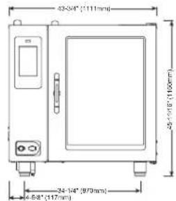
text_image
43-34" (111mm) 39-110" (110mm) 34-14" (979mm) 4-68" (147mm)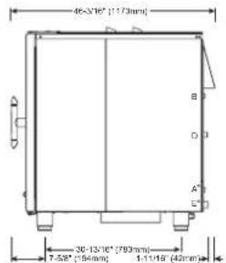
text_image
45-3/16" (1173mm) 30-13/16" (793mm) 7-58" (194mm) 1-11/16" (42mm)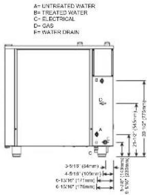
text_image
A= UNTREATED WATER B= TREATED WATER C= ELECTRICAL D= GAS E= WATER DRAIN 3-5/18" (64mm) 4-5/18" (105mm) 6-13/16" (171mm) 6-15/16" (176mm)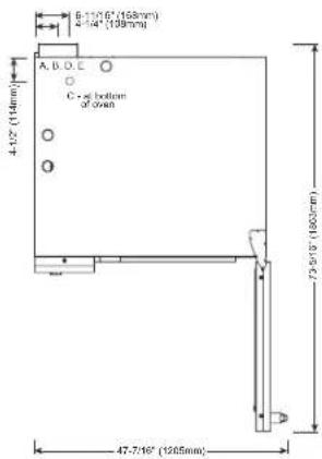
text_image
6-15/16" (158mm) 4-14" (139mm) A, B, C C - at bottom of 3mm 4.52" (14mm) 75.50" (1600mm) 47-7.16" (1205mm)


CE EAC IP X5

| WATER REQUIREMENTS | WATER QUALITY STANDARDS | ||
| TWO (2) COLD WATER INLETS - DRINKING QUALITYONE (1) TREATED WATER INLET: 3/4" NPT* Can manifold off ofONE (1) UNTREATED WATER INLET: 3/4" NPT* one 3/4" lineLINE PRESSURE: 30 psi minimum dynamic and 90 psi maximum static (200 to 600 kPa)WATER DRAIN: 1-1/2" (40mm) CONNECTION WITH A VERTICAL VENT TO EXTEND ABOVE THE EXHAUST VENT.MATERIALS MUST WITHSTAND TEMPERATURES UP TO 200°F (93°C). | It is the sole responsibility of the owner/operator/purchaser of this equipment to verify that the incoming water supply is comprehensively tested and if required, a means of "water treatment" provided that would meet compliance requirements with the published water quality standards shown below.Non-compliance with these minimum standards will potentially damage this equipment and/or components and void the original equipment manufacturer's warranty. Alto-Shaam recommends using OptiPure® [www.optipurewater.com] products to properly treat your water.Contaminant Inlet Water RequirementsFree Chlorine Less than 0.1 ppm (mg/L)Hardness 30-70 ppmChloride Less than 30 ppm (mg/L)pH 7.0 to 8.5Silica Less than 12 ppm (mg/L)Total Dissolved Solids (tds) 50-125 ppm | ||
| CLEARANCE REQUIREMENTS | |||
| LEFT: 0" (0mm) | 18" (457mm) RECOMMENDED SERVICE ACCESS | ||
| RIGHT: 0" (0mm)NON-COMBUSTIBLE SURFACES | 2" (51mm)DOOR SWING OR COMBUSTIBLE SURFACES | ||
| TOP: 20" (508mm) FOR AIR MOVEMENT | |||
| BACK: 4" (102mm)4-5/16" (109mm) OPTIONAL PLUMBING KIT | BOTTOM: 5-1/8" (130mm)FOR LEGS, AIR INTAKE | ||
| INSTALLATION REQUIREMENTS | |||
| · Oven must be installed level. · Hood installation is required.· Water supply shut-off valve and back-flow preventer when required by local code. | |||
| HOOK-UP: 3/4" NPT | ||||||||||||
| RATED THERMAL LOAD CONNECTED PRESSURE | ||||||||||||
| NORTH AMERICA INTERNATIONAL NORTH AMERICA INTERNATIONAL | ||||||||||||
| Natural Gas/Propane G20, G25, G31 Natural Gas Propane | G20 20mbar | |||||||||||
| Gross Heating Value (HHV) Net Heating Value (LHV) Minimum: 5.5" W.C. dynamic Minimum: 9" W.C. dynamic | G25 20mbar | |||||||||||
| 133,000 Btu / hr | 36.0 kW | Maximum: 14" W.C. static | Maximum: 14" W.C. static | G31 30mbar | ||||||||
| ELECTRICAL - CTP10-20G (DEDICATED CIRCUIT REQUIRED) | WITH COMBISMOKER® OPTION | |||||||||||
| VOLTAGE | PH | HZ | AWG | CONNECTION no cord, no plug | AMPS | BREAKER | kW | CONNECTION no cord, no plug | AMPS | BREAKER | kW | |
| →→→ | 120 | 1 | 60 | 14 | L1, N, G | 6.8 | 20 | .84 | L1, N, G | 12.0 | 20 | 1.46 |
| ←→ | 208 – 240 | 1+ | 50/60 | 14 | L1, L2/N, G | 4.8 – 4.2 | 15 | 1.0 | L1, L2/N, G | 7.3 – 7.1 | 15 | 1.5 – 1.7 |
| ←→ | 208 – 240 | 3 | 50/60 | 14 | L1, L2, L3, G | 4.8 – 4.2 | 15 | 1.0 | L1, L2, L3, G | 7.3 – 7.1 | 15 | 1.5 – 1.7 |
| ←→ | 380 – 415 | 3 | 50/60 | 14 | L1, L2, L3, N, G | 4.6 – 4.2 | 15 | 1.0 | L1, L2, L3, N, G | 7.2 – 7.1 | 15 | 1.6 – 1.7 |
NORTH AMERICA VOLTAGE CHOICE GROUND FAULTOR RESIDUAL CURRENT PROTECTION DEVICE MUST ACCOMMODATE A LEAKAGE CURRENT OF 20mA INTERNATIONAL VOLTAGE CHOICE ELECTRICAL SERVICE CHARGE APPLIES
| WEIGHT | PAN CAPACITY | STANDARD MODEL | WITH COMBISMOKER® OPTION | ||
| NET | 760 lbs EST | 345 kg | FULL-SIZE: 20" x 12" x 2-1/2*GN 1/1: 530 x 325 x 65mmGN 2/1: 650 x 530 x 65mm**FULL-SIZE SHEET: 18" x 26" x 1" | Twenty-two (22)Twenty-two (22)Eleven (11)Eleven (11) | Twenty-one (21)Twenty-one (21)Ten (10)Eleven (11) |
| SHIP | 800 lbs* | 363 kg* | |||
| SHIP DIMENSIONS | PRODUCT CAPACITY | ||||
| (L x W x H) 56" x 49" x 65"(1422mm x 1245mm x 1651mm)* | PRODUCT MAXIMUM | 240 lb (109 kg) | |||
| VOLUME MAXIMUM | 150 quarts (190 liters) | ||||
| *DOMESTIC GROUND SHIPPING INFORMATION. CONTACT FACTORY FOR EXPORT WEIGHT AND DIMENSIONS. | **ON WIRE SHELVES ONLY. ADDITIONAL WIRE SHELVES REQUIRED FOR MAXIMUM CAPACITY | ||||

text_image
43 2/4" (1111mm) 45-11/9" (1160mm) 34 1/4" (870mm) 4-5/8" (117mm)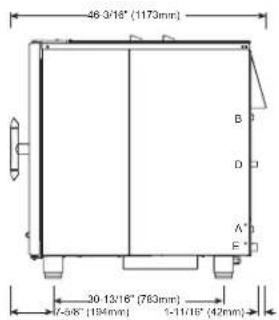
text_image
46 3/18" (1173mm) B D A" F" 30 13/16" (763mm) 7-5/8" (194mm) 1-11/18" (42mm)A=UNTREATED WATER
B-TREATED WATER
C= ELECTRICAL
D= GAS
E= WATER DRAIN
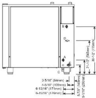
text_image
3-5/16" (84mm) 4-5/16" (109mm) 6-13/16" (171mm) 6-15/16" (176mm) 5-7/8" (143mm) 9-1/16" (230mm) 2x1.12" (545mm) 30-12" (759mm)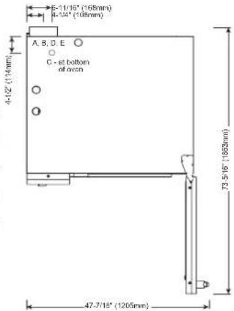
text_image
5-11/16" (168mm) 4-12/4" (108mm) A, B, C, D, E C - at bottom of oven 4-12" (114mm) 73.5/16" (1083mm) 47.7/18" (1205mm)


IP X5

| WATER REQUIREMENTS | WATER QUALITY STANDARDS | ||||||||
| TWO (2) COLD WATER INLETS - DRINKING QUALITYONE (1) TREATED WATER INLET: 3/4" NPT* * Can manifold off ofONE (1) UNTREATED WATER INLET: 3/4" NPT* one 3/4" lineLINE PRESSURE: 30 psi minimum dynamic and 90 psi maximum static (200 to 600 kPa)WATER DRAIN: 1-1/2" (40mm) CONNECTION WITH A VERTICAL VENT TO EXTEND ABOVE THE EXHAUST VENT.MATERIALS MUST WITHSTAND TEMPERATURES UP TO 200°F (93°C). | It is the sole responsibility of the owner/operator/purchaser of this equipment to verify that the incoming water supply is comprehensively tested and if required, a means of "water treatment" provided that would meet compliance requirements with the published water quality standards shown below.Non-compliance with these minimum standards will potentially damage this equipment and/or components and void the original equipment manufacturer's warranty. Alto-Shaam recommends using OptiPure® [www.optipurewater.com] products to properly treat your water.Contaminant Inlet Water RequirementsFree Chlorine Less than 0.1 ppm (mg/L)Hardness 30-70 ppmChloride Less than 30 ppm (mg/L)pH 7.0 to 8.5Silica Less than 12 ppm (mg/L)Total Dissolved Solids (Ids) 50-125 ppm | ||||||||
| CLEARANCE REQUIREMENTS | |||||||||
| LEFT: 0" (0mm) | 18" (457mm) RECOMMENDED SERVICE ACCESS | ||||||||
| RIGHT: 0" (0mm) NON-COMBUSTIBLE SURFACES | 2" (51mm) DOOR SWING OR COMBUSTIBLE SURFACES | ||||||||
| TOP: 20" (508mm) FOR AIR MOVEMENT | |||||||||
| BACK: 4" (102mm)4-5/16" (109mm) OPTIONAL PLUMBING KIT | BOTTOM: 5-1/8" (130mm)FOR LEGS, AIR INTAKE | ||||||||
| INSTALLATION REQUIREMENTS | |||||||||
| · Oven must be installed level. · Hood installation is required.· Water supply shut-off valve and back-flow preventer when required by local code. | |||||||||
| GAS REQUIREMENTS (GAS TYPE MUST BE SPECIFIED ON ORDER) | |||||||||
| HOOK-UP: 3/4" NPT | |||||||||
| RATED THERMAL LOAD CONNECTED PRESSURE | |||||||||
| NORTH AMERICA INTERNATIONAL NORTH AMERICA INTERNATIONAL | |||||||||
| Natural Gas/Propane G20, G25, G31 Natural Gas Propane | G20 20mbarG25 20mbarG31 30mbar | ||||||||
| Gross Heating Value (HHV) Net121,000 Btu / hr | Heating Value (LHV) Minimum: 5.5" W32.0 kW | C. dynamic Minimum: 9" W.C. dynamicMaximum: 14" W.C. static | Maximum: 14" W.C. static | ||||||
| ELECTRICAL - CTC10-20G (DEDICATED CIRCUIT REQUIRED) | |||||||||
| VOLTAGE | PH | HZ | AWG | CONNECTION | AMPS | BREAKER | kW | ||
| →→→ | 120 | 1 | 60 | 14 | L1, N, G - no cord, no plug | 7.0 | 20 | .84 | |
| →→ | 208 – 240 | 3 | 50/60 | 14 | L1, L2, L3, G - no cord, no plug | 4.8 – 4.2 | 15 | 1.0 | |
| →→ | 380 – 415 | 3 | 50/60 | 14 | L1, L2, L3, N, G - no cord, no plug | 4.6 – 4.2 | 15 | 1.0 | |
NORTH AMERICA VOLTAGE CHOICE GROUND FAULT OR RESIDUAL CURRENT PROTECTION DEVICE MUST ACCOMMODATE A LEAKAGE CURRENT OF 20mA INTERNATIONAL VOLTAGE CHOICE
| WEIGHT | SHIP DIMENSIONS | PAN CAPACITY | ||||
| NET | 760 lbs est 345 kg | (L x W x H) 56" x 49" x 65"* | FULL-SIZE: | 20" x 12" x 2-1/2" | Twenty-two (22) | PRODUCT MAXIMUM: 240 lb (109 kg) |
| SHIP | 800 lbs* 363 kg* | (1422 x 1245 x 1651mm)* | GN 1/1: | 530 x 325 x 65mm | Twenty-two (22) | VOLUME MAXIMUM: 150 quarts (190 liters) |
| *DOMESTIC GROUND SHIPPING INFORMATION. CONTACT FACTORY FOR EXPORT WEIGHT AND DIMENSIONS. | GN 2/1: | 650 x 530 x 65mm Eleven (11) | **ON WIRE SHELVES ONLY, ADDITIONAL WIRE SHELVES REQUIRED FOR MAXIMUM CAPACITY | |||
| **FULL-SIZE SHEET: | 18" x 26" x 1" Eleven (11) | |||||
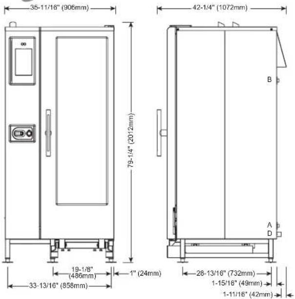
text_image
35-11/16" (906mm) 79-1/4" (2012mm) 42-1/4" (1072mm) 19-1/8" (486mm) 33-13/16" (858mm) 1" (24mm) 28-13/16" (732mm) 1-15/16" (49mm) 1-11/16" (42mm)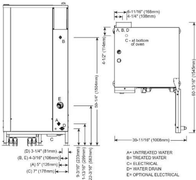
text_image
6-11/16" (168mm) 4-1/4" (108mm) A, B, D C - at bottom of oven 4-1/2" (114mm) 59-1/4" (1504mm) 60-13/16" (1545mm) 39-11/16" (1008mm) A= UNTREATED WATER B= TREATED WATER C= ELECTRICAL D= WATER DRAIN E= OPTIONAL ELECTRICAL (D) 3-1/4" (81mm) (B, E) 4-3/16" (106mm) (A) 5" (126mm) (C) 7" (178mm) 9-3/16" (233mm) 11-13/16" (299mm) 22-3/16" (563mm)

CE EAC IP X5
WATER REQUIREMENTS
| TWO (2) COLD WATER INLETS - DRINKING QUALITYONE (1) TREATED WATER INLET: 3/4" NPT* * Can manifold off ofONE (1) UNTREATED WATER INLET: 3/4" NPT* one 3/4" lineLINE PRESSURE: 30 psi minimum dynamic and 90 psi maximum static (200 to 600 kPa)WATER DRAIN: 1-1/2" (40mm) CONNECTION WITH A VERTICAL VENT TO EXTEND ABOVE THE EXHAUST VENT.MATERIALS MUST WITHSTAND TEMPERATURES UP TO 200°F (93°C). | |
| CLEARANCE REQUIREMENTS | |
| LEFT: 0" (0mm) | 18" (457mm) RECOMMENDED SERVICE ACCESS |
| RIGHT: 0" (0mm) NON-COMBUSTIBLE SURFACES | 2" (51mm) DOOR SWING ORCOMBUSTIBLE SURFACES |
| TOP: 20" (508mm) FOR AIR MOVEMENT | |
| BACK: 4" (102mm)4-5/16" (109mm) OPTIONAL PLUMBING KIT | BOTTOM: 5-1/8" (130mm)FOR LEGS, AIR INTAKE |
| INSTALLATION REQUIREMENTS | |
| • Oven must be installed level. • Hood installation is required.• Water supply shut-off valve and back-flow preventer when required by local code. | |
| DIMENSIONS: H x W x D | |
| EXTERIOR:79-1/4" x 35-11/16" x 42-1/4" (2012mm x 906mm x 1072mm) | |
| EXTERIOR WITH RECESSED DOOR:79-1/4" x 40-11/16" x 42-1/4" (2012mm x 1033mm x 1072mm) | |
| INTERIOR:60-7/16" x 16-1/4" x 28-1/16" (1535mm x 411mm x 712mm) | |
| WATER QUALITY STANDARDS | |
| It is the sole responsibility of the owner/operator/purchaser of this equipment to verify that the incoming water supply is comprehensively tested and if required, a means of "water treatment" provided that would meet compliance requirements with the published water quality standards shown below. Non-compliance with these minimum standards will potentially damage this equipment and/or components and void the original equipment manufacturer's warranty. Alto-Shaam recommends using OptiPure® [www.optipurewater.com] products to properly treat your water. | |
| Contaminant | Inlet Water Requirements |
| Free Chlorine | Less than 0.1 ppm (mg/L) |
| Hardness | 30-70 ppm |
| Chloride | Less than 30 ppm (mg/L) |
| pH | 7.0 to 8.5 |
| Silica | Less than 12 ppm (mg/L) |
| Total Dissolved Solids (tds) | 50-125 ppm |
| ELECTRICAL - CTP20-10E (NO CORD, NO PLUG, DEDICATED CIRCUIT REQUIRED) | WITH COMBISMOKER® OPTION | ||||||||||||||||
| ECO STANDARD | **PROpowerTM OPTION | ECO STANDARD | **PROpowerTM OPTION | ||||||||||||||
| VOLTAGE | PH | HZ | AWG | CONNECTION | AMPS | kW | BREAKER | AMPS | kW | BREAKER | AMPS | kW | BREAKER | AMPS | kW | BREAKER | |
| 208 – 240 | 3 | 50/60 | 1 – 1/0 | L1, L2, L3, G | 78.8 – 90.9 | 28.4 – 37.8 | 80 – 90 | 98.8 – 114 | 33.2 – 44.2 | 100 – 125 | 81.3 – 93.8 | 28.9 – 38.5 | 90 – 100 | 101.3 – 116.9 | 33.7 – 44.9 | 110 – 125 | |
| 380 – 415 | 3 | 50/60 | 4 – 3 | L1, L2, L3, N, G | 48.2 – 52.5 | 32.3 – 37.8 | 63 | 60.5 – 65.8 | 37.1 – 44.2 | 63 – 80 | 50.9 – 55.4 | 32.8 – 38.5 | 63 | 63.1 – 68.7 | 37.7 – 44.9 | 100 | |
| 440 – 480 | 3* | 50/60 | 6 – 4 | L1, L2, L3, G | 41.7 – 45.5 | 32.4 – 37.8 | 50 | 52.2 – 57 | 37.2 – 44.2 | 60 | 43 – 46.9 | 32.9 – 38.5 | 50 | 53.6 – 58.5 | 37.8 – 44.9 | 60 | |
*ELECTRICAL SERVICE CHARGE APPLIES
**NO-COST OPTION ON ELECTRIC MODELS
| WEIGHT | SHIP DIMENSIONS | PAN CAPACITY | ||
| NET 905 lbs est 411 kgSHIP 1052 lbs* 477 kg* | (L x W x H) 56" x 45" x 87**(1422 x 1143 x 2210mm)* | FULL-SIZE: 20" x 12" x 2-1/2" Twenty (20)GN 1/1: 530 x 325 x 65mm Twenty (20)**HALF-SIZE SHEET: 18" x 13" x 1" Twenty (20) | PRODUCT MAXIMUM: 240 lb (109 kg) | |
| VOLUME MAXIMUM: 150 quarts (190 liters) | ||||
| *DOMESTIC GROUND SHIPPING INFORMATION. CONTACTFACTORY FOR EXPORTWEIGHT AND DIMENSIONS. | **ON WIRE SHELVES ONLY. ADDITIONAL WIRE SHELVESREQUIRED FOR MAXIMUM CAPACITY | |||

text_image
35-11/16" (906mm) 79-1/4" (2012mm) 42-1/4" (1072mm) 19-1/8" (486mm) 33-13/16" (858mm) 1" (24mm) 28-13/16" (732mm) 1-15/16" (49mm) 1-11/16" (42mm)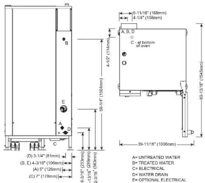
text_image
6-11/16" (168mm) 4-1/4" (108mm) A, B, D C - at bottom of oven 60-13/16" (154.5mm) 39-11/16" (1008mm) A= UNTREATED WATER B= TREATED WATER C= ELECTRICAL D= WATER DRAIN E= OPTIONAL ELECTRICAL (D) 3-1/4" (81mm) (B, E) 4-3/16" (106mm) (A) 5" (126mm) (C) 7" (178mm) 59-1/4" (1504mm)

CE EAC IP X5
| WATER REQUIREMENTS | WATER QUALITY STANDARDS | ||||||
| TWO (2) COLD WATER INLETS - DRINKING QUALITYONE (1) TREATED WATER INLET: 3/4" NPT* * Can manifold off ofONE (1) UNTREATED WATER INLET: 3/4" NPT* one 3/4' lineLINE PRESSURE: 30 psi minimum dynamic and 90 psi maximum static (200 to 600 kPa)WATER DRAIN: 1-1/2" (40mm) CONNECTION WITH A VERTICAL VENT TO EXTEND ABOVE THE EXHAUST VENT.MATERIALS MUST WITHSTAND TEMPERATURES UP TO 200°F (93°C). | It is the sole responsibility of the owner/operator/purchaser of this equipment to verify that the incoming water supply is comprehensively tested and if required, a means of "water treatment" provided that would meet compliance requirements with the published water quality standards shown below.Non-compliance with these minimum standards will potentially damage this equipment and/or components and void the original equipment manufacturer's warranty. Alto-Shaam recommends using OptiPure® [www.optipurewater.com] products to properly treat your water.Contaminant Inlet Water RequirementsFree Chlorine Less than 0.1 ppm (mg/L)Hardness 30-70 ppmChloride Less than 30 ppm (mg/L)pH 7.0 to 8.5Silica Less than 12 ppm (mg/L)Total Dissolved Solids (tds) 50-125 ppm | ||||||
| CLEARANCE REQUIREMENTS | |||||||
| LEFT: 0" (0mm) | 18" (457mm) RECOMMENDED SERVICE ACCESS | ||||||
| RIGHT: 0" (0mm) NON-COMBUSTIBLE SURFACES | 2" (51mm) DOOR SWING OR COMBUSTIBLE SURFACES | ||||||
| TOP: 20" (508mm) FOR AIR MOVEMENT | |||||||
| BACK: 4" (102mm)4-5/16" (109mm) OPTIONAL PLUMBING KIT | BOTTOM: 5-1/8" (130mm)FOR LEGS, AIR INTAKE | ||||||
| INSTALLATION REQUIREMENTS | |||||||
| • Oven must be installed level. • Hood installation is required.• Water supply shut-off valve and back-flow preventer when required by local code. | |||||||
| ELECTRICAL (NO CORD, NO PLUG, DEDICATED CIRCUIT REQUIRED) | |||||||
| MODEL VOLTAGE PH HZ AMPS KW BREAKER AWG CONNECTION | |||||||
| CTC20-10E | 208-240 | 3 | 50/60 | 78.8-90.9 | 28.4-37.8 | 80-90 | 1-1/0 |
| 380-415 | 3 | 50/60 | 48.2-52.5 | 32.3-37.8 | 63 | 4-3 | |
| 440-480 | 3* | 50/60 | 41.7-45.5 | 32.4-37.8 | 50 | 6-4 | |
*ELECTRICAL SERVICE CHARGE APPLIES
| WEIGHT | SHIP DIMENSIONS PAN CAPACITY | ||||
| NET 905 lbs est 411 kg | (L x W x H) 56" x 45" x 87"* | FULL-SIZE: 20" x 12" x 2-1/2" Twenty (20) | PRODUCT MAXIMUM: 240 lb (109 kg) | ||
| SHIP 1052 lbs* 477 kg* | (1422 x 1143 x 2210mm)* | GN 1/1: 530 x 325 x 65mm Twenty (20) | VOLUME MAXIMUM: 150 quarts (190 liters) | ||
| *DOMESTIC GROUND SHIPPING INFORMATION. CONTACT FACTORY FOR EXPORT WEIGHT AND DIMENSIONS. | **HALF-SIZE SHEET: 18" x 13" x 1" Twenty (20) | **ON WIRE SHELVES ONLY. ADDITIONAL WIRE SHELVES REQUIRED FOR MAXIMUM CAPACITY | |||

text_image
35-11'19" (X80mm) 42-13" (1672mm) 79-14" (2012mm) 19-19" (480mm) 33-13'16" (868mm) 1" (24mm) 29-13'19" (732mm) 1-15'16" (48mm) 1-11'16" (42mm)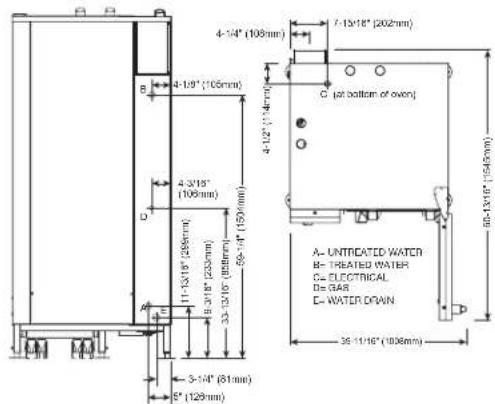
text_image
4-1/9" (105mm) 4-3/18" (106mm) 6-1/16" (202mm) 6-1/16" (150mm) A- UNTRIDATED WATER B- TREATED WATER C- ELECTRICAL D- 34.8 E- WATER DRAIN 36-11/16" (1008mm) 3-1/4" (81mm) 5" (128mm)


| WATER REQUIREMENTS | WATER QUALITY STANDARDS | ||
| TWO (2) COLD WATER INLETS - DRINKING QUALITYONE (1) TREATED WATER INLET: 3/4" NPT* · Can manifold off ofONE (1) UNTREATED WATER INLET: 3/4" NPT* one 3/4" lineLINE PRESSURE: 30 psi minimum dynamic and 90 psi maximum static (200 to 600 kPa)WATER DRAIN: 1-1/2" (40mm) CONNECTION WITH A VERTICAL VENT TO EXTENDABOVE THE EXHAUST VENT.MATERIALS MUST WITHSTAND TEMPERATURES UP TO 200°F (93°C). | It is the sole responsibility of the owner/operator/purchaser of this equipment to verify that the incoming water supply is comprehensively tested and if required, a means of "water treatment" provided that would meet compliance requirements with the published water quality standards shown below.Non-compliance with these minimum standards will potentially damage this equipment and/or components and void the original equipment manufacturer's warranty. Alto-Shaam recommends using OptiPure® [www.optipurewater.com] products to properly treat your water.Contaminant Inlet Water RequirementsFree Chlorine Less than 0.1 ppm (mg/L)Hardness 30-70 ppmChloride Less than 30 ppm (mg/L)pH 7.0 to 8.5Silica Less than 12 ppm (mg/L)Total Dissolved Solids (tds) 50-125 ppm | ||
| CLEARANCE REQUIREMENTS | |||
| LEFT: 0" (0mm) | 18" (457mm) RECOMMENDED SERVICE ACCESS | ||
| RIGHT: 0" (0mm) NON-COMBUSTIBLE SURFACES | 2" (51mm) DOOR SWING OR COMBUSTIBLE SURFACES | ||
| TOP: 20" (508mm) FOR AIR MOVEMENT | |||
| BACK: 4" (102mm)4-5/16" (109mm) OPTIONAL PLUMBING KIT | BOTTOM: 5-1/8" (130mm)FOR LEGS, AIR INTAKE | ||
| INSTALLATION REQUIREMENTS | |||
| · Oven must be installed level. · Hood installation is required.· Water supply shut-off valve and back-flow preventer when required by local code. | |||
| GAS REQUIREMENTS (GAS TYPE MUST BE SPECIFIED ON ORDER) | ||||||||||||
| HOOK-UP: 3/4" NPT | ||||||||||||
| RATED THERMAL LOAD CONNECTED PRESSURE | ||||||||||||
| NORTH AMERICA INTER | NATIONAL NORTH AMERICA IN | INTERNATIONAL | ||||||||||
| Natural Gas/Propane G20, | G25, G31 Natural Gas Propane | G20 20mbar | ||||||||||
| Gross Heating Value (HHV) Net 160,000 Btu / hr | Heating Value (LHV) Minimum: 42.5 kW | 5.5" W.C. dynamic Minimum: 9" W.C. maximum: 14" W.C. static | dynamic Maximum: 14" W.C. static | G25 20mbar | ||||||||
| G31 30mbar | ||||||||||||
| ELECTRICAL - CTP20-10G (DEDICATED CIRCUIT REQUIRED) | WITH COMBISMOKER*OPTION | |||||||||||
| VOLTAGE | PH | HZ | AWG | CONNECTION no cord, no plug | AMPS | BREAKER | kW | CONNECTION no cord, no plug | AMPS | BREAKER | kW | |
| →→% | 120 | 1 | 60 | 14 | L1, N, G | 13.6 | 20 | 1.7 | L1, N, G | 18.4 | 25 | 2.3 |
| →→ | 208 – 240 | 1+ | 50/60 | 14 | L1, L2/N, G | 9.6 – 8.4 | 15 | 2.0 | L1, L2/N, G | 12.1 – 11.3 | 15 | 2.5 – 2.7 |
| →→ | 208 – 240 | 3 | 50/60 | 14 | L1, L2, L3, G | 9.6 – 8.4 | 15 | 2.0 | L1, L2, L3, G | 12.1 – 11.3 | 15 | 2.5 – 2.7 |
| → | 380 – 415 | 3 | 50/60 | 14 | L1, L2, L3, N, G | 9.2 – 8.4 | 15 | 2.0 | L1, L2, L3, N, G | 11.8 – 11.3 | 15 | 2.6 – 2.7 |
NORTH AMERICA VOLTAGE CHOICE GROUND FAULT OR RESIDUAL CURRENT PROTECTION DEVICE MUST ACCOMMODATE A LEAKAGE CURRENT OF 20mA INTERNATIONAL VOLTAGE CHOICE ELECTRICAL SERVICE CHARGE APPLIES
| WEIGHT | SHIP DIMENSIONS | PAN CAPACITY | ||||
| NET | 905 lbs est 411 kg | (L x W x H) 45" x 56" x 87"* | FULL-SIZE: | 20" x 12" x 2-1/2" | Twenty (20) | PRODUCT MAXIMUM: 240 lb (109 kg) |
| SHIP | 1175 lbs* 533 kg* | (1143 x 1422 x 2210mm)* | GN 1/1: | 530 x 325 x 65mm | Twenty (20) | VOLUME MAXIMUM: 150 quarts (190 liters) |
| *DOMESTIC GROUND SHIPPING INFORMATION, CONTACT FACTORY FOR EXPORT WEIGHT AND DIMENSIONS. | **HALF-SIZE SHEET: | 18" x 13" x 1" | Twenty (20) | **ON WIRE SHELVES ONLY, ADDITIONAL WIRE SHELVES REQUIRED FOR MAXIMUMCAPACITY | ||

text_image
35-11/16" (568mm) 42-14" (1072mm) 79-14" (2012mm) 10-14" (488mm) 33-13/16" (859mm) 1" (24mm) 28-13/16" (732mm) 1-15/16" (49mm) 1-15/16" (42mm) 4-14" (108mm) 4-12" (114mm) 4-3/16" (109mm) 4-3/16" (288mm) 4-3/16" (233mm) 33-13/16" (458mm) 3-14" (81mm) 5" (129mm) 7-15/16" (202mm) C (at bottom of oven) A= UNIPATED WATER B= TREATED WATER C= ELECTRICAL D= GAS E= WATER DRAIN 38-11/16" (1000mm)


WATER REQUIREMENTS
| TWO (2) COLD WATER INLETS - DRINKING QUALITYONE (1) TREATED WATER INLET: 3/4" NPT* * Can manifold off ofONE (1) UNTREATED WATER INLET: 3/4" NPT* one 3/4" lineLINE PRESSURE: 30 psi minimum dynamic and 90 psi maximum static (200 to 600 kPa)WATER DRAIN: 1-1/2" (40mm) CONNECTION WITH A VERTICAL VENT TO EXTEND ABOVE THE EXHAUST VENT.MATERIALS MUST WITHSTAND TEMPERATURES UP TO 200°F (93°C). | |
| CLEARANCE REQUIREMENTS | |
| LEFT: 0" (0mm) | 18" (457mm) RECOMMENDED SERVICE ACCESS |
| RIGHT: 0" (0mm) NON-COMBUSTIBLE SURFACES | 2" (51mm) DOOR SWING ORCOMBUSTIBLE SURFACES |
| TOP: 20" (508mm) FOR AIR MOVEMENT | |
| BACK: 4" (102mm)4-5/16" (109mm) OPTIONAL PLUMBING KIT | BOTTOM: 5-1/8" (130mm)FOR LEGS, AIR INTAKE |
| INSTALLATION REQUIREMENTS | |
| • Oven must be installed level. • Hood installation is required.• Water supply shut-off valve and back-flow preventer when required by local code. | |
GAS REQUIREMENTS (GAS TYPE MUST BE SPECIFIED ON ORDER)
| HOOK-UP: 3/4" NPT | |||||||||
| RATED THERMAL LOAD CONNECTED PRESSURE | |||||||||
| NORTH AMERICA INTERNATIONAL NORTH AMERICA INTERNATIONAL | |||||||||
| Natural Gas/Propane G20, G25, G31 Natural Gas Propane | G20 20mbar | ||||||||
| Gross Heating Value (HHV) Net 140,000 Btu / hr | Heating Value (LHV) Minimum: 5.5" W.C. dynamic Minimum: 9" W.C. dynamic Maximum: 14" W.C. static | G25 20mbar | |||||||
| 37.0 kW | G31 30mbar | ||||||||
| ELECTRICAL - CTC20-10G (DEDICATED CIRCUIT REQUIRED) | |||||||||
| VOLTAGE | PH | HZ | AWG | CONNECTION | AMPS | BREAKER | kW | ||
| ←→ | 120 | 1 | 60 | 12 | L1, N, G - no cord, no plug | 13.0 | 20 | 1.7 | |
| ←→ | 208 – 240 | 3 | 50/60 | 14 | L1, L2, L3, G - no cord, no plug | 9.6 – 8.4 | 15 | 2.0 | |
| ←→ | 380 – 415 | 3 | 50/60 | 14 | L1, L2, L3, N, G - no cord, no plug | 9.2 – 8.4 | 15 | 2.0 | |
NORTH AMERICA VOLTAGECHOICE GROUND FAULT OR RESIDUAL CURRENTPROTECTION DEVICE MUST ACCOMMODATE A LEAVAGE CURRENT OF 20mA INTERNATIONAL VOLTAGE CHOICE
| WEIGHT | SHIP DIMENSIONS | PAN CAPACITY | ||||
| NET 905 lbs est 411 kgSHIP 1175 lbs* 533 kg* | (L x W x H) 45" x 56" x 87"(1143 x 1422 x 2210mm)* | FULL-SIZE:GN 1/1:***HALF-SIZE SHEET: | 20" x 12" x 2-1/2"530 x 325 x 65mm18" x 13" x 1" | Twenty (20)Twenty (20)Twenty (20) | PRODUCT MAXIMUM: 240 lb (109 kg)VOLUME MAXIMUM: 150 quarts (190 liters)**ON WIRE SHELVES ONLY. ADDITIONAL WIRE SHELVES REQUIRED FOR MAXIMUM CAPACITY. | |
| *DOMESTIC GROUND SHIPPING INFORMATION. CONTACT FACTORY FOREXPORT WEIGHT AND DIMENSIONS. | ||||||
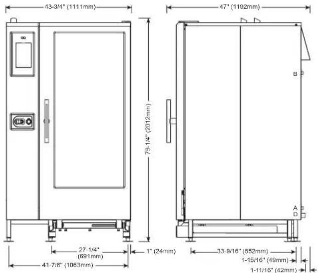
text_image
43-3/4" (1111mm) 79-14" (2012mm) 47" (1192mm) 27-1/4" (691mm) 41-7/8" (1063mm) 1" (24mm) 33-9/16" (852mm) 1-15/16" (49mm) 1-11/16" (42mm)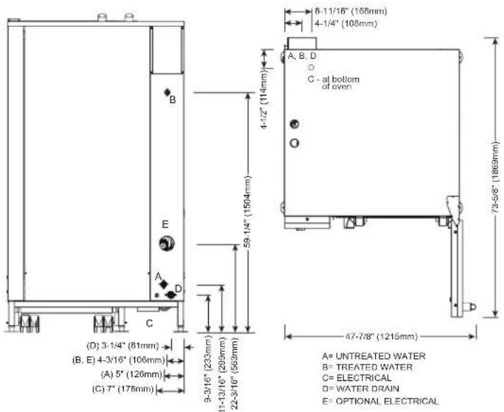
text_image
6-11/16" (168mm) 4-1/4" (108mm) A, B, D C - al bottom of oven 73-68" (1869mm) 47-7/8" (1215mm) A= UNTREATED WATER B= TREATED WATER C= ELECTRICAL D= WATER DRAIN E= OPTIONAL ELECTRICAL

CE EAC IP X5
| WATER REQUIREMENTS | WATER QUALITY STANDARDS | |||||||||||||||||
| TWO (2) COLD WATER INLETS - DRINKING QUALITYONE (1) TREATED WATER INLET: 3/4" NPT* * Can manifold off ofONE (1) UNTREATED WATER INLET: 3/4" NPT* one 3/4" lineLINE PRESSURE: 30 psi minimum dynamic and 90 psi maximum static (200 to 600 kPa)WATER DRAIN: 1-1/2" (40mm) CONNECTION WITH A VERTICAL VENT TO EXTEND ABOVE THEEXHAUST VENT.MATERIALS MUST WITHSTAND TEMPERATURES UP TO 200°F (93°C). | It is the sole responsibility of the owner/operator/purchaser of this equipment to verify that the incoming water supply is comprehensively tested and if required, a means of "water treatment" provided that would meet compliance requirements with the published water quality standards shown below.Non-compliance with these minimum standards will potentially damage this equipment and/or components and void the original equipment manufacturer's warranty. Alto-Shaam recommends using OptiPure® [www.optipurewater.com] products to properly treat your water.Contaminant Inlet Water RequirementsFree Chlorine Less than 0.1 ppm (mg/L)Hardness 30-70 ppmChloride Less than 30 ppm (mg/L)pH 7.0 to 8.5Silica Less than 12 ppm (mg/L)Total Dissolved Solids (lds) 50-125 ppm | |||||||||||||||||
| CLEARANCE REQUIREMENTS | ||||||||||||||||||
| LEFT: 0" (0mm) | 18" (457mm) RECOMMENDED SERVICE ACCESS | |||||||||||||||||
| RIGHT: 0" (0mm) NON-COMBUSTIBLE SURFACES | 2" (51mm) DOOR SWING OR COMBUSTIBLE SURFACES | |||||||||||||||||
| TOP: 20" (508mm) FOR AIR MOVEMENT | ||||||||||||||||||
| BACK: 4" (102mm)4-5/16" (109mm) OPTIONAL PLUMBING KIT | BOTTOM: 5-1/8" (130mm)FOR LEGS. AIR INTAKE | |||||||||||||||||
| INSTALLATION REQUIREMENTS | ||||||||||||||||||
| · Oven must be installed level. · Hood installation is required.· Water supply shut-off valve and back-flow preventer when required by local code. | ||||||||||||||||||
| ELECTRICAL - CTP20-20E (NO CORD, NO PLUG, DEDICATED CIRCUIT REQUIRED) | WITH COMBISMOKER® OPTION | |||||||||||||||||
| ECO STANDARD | **PROpowerTM OPTION | ECO STANDARD | **PROpowerTM OPTION | |||||||||||||||
| VOLTAGE | PH | HZ | AWG | CONNECTION | AMPS | KW | BREAKER | AMPS | KW | BREAKER | AMPS | KW | BREAKER | AMPS | KW | BREAKER | ||
| 208-240 | 3 | 50/60 | 4/0 | L1, L2, L3, G | 137.6-158.8 | 49.6-66 | 150-175 | 172-198.5 | 57.8-77 | 175-200 | 140.1-161.6 | 50.1-66.7 | 150-175 | 174.5-201.3 | 58.4-77.7 | 200-225 | ||
| 380-415 | 3 | 50/60 | 1-1/0 | L1, L2, L3, N, G | 84.2-91.7 | 56.4-66 | 100 | 105.3-114.6 | 64.7-77 | 125 | 86.9-94.5 | 56.9-66.7 | 100 | 107.9-117.5 | 65.3-77.7 | 150 | ||
| 440-480 | 3* | 50/60 | 2-1 | L1, L2, L3, G | 72.7-79.4 | 56.5-66 | 80 | 90.9-99.2 | 64.8-77 | 100 | 74.1-80.8 | 57.1-66.7 | 80-90 | 92.3-100.7 | 65.4-77.7 | 100 | ||
WATER REQUIREMENTS
*ELECTRICAL SERVICE CHARGE APPLIES **NO-COST OPTION ON ELECTRIC MODELS
| WEIGHT SHIP DIMENSIONS | PAN CAPACITY | ||
| NET 1100 lbs est 499 kgSHIP 1157 lbs* 525 kg* (1346 x 1346 x 2210mm)* | (L x W x H) 53" x 53" x 87** | FULL-SIZE: 20" x 12" x 2-1/2" Forty (40)GN 1/1: 530 x 325 x 65mm Forty (40) | PRODUCT MAXIMUM: 480 lb (218 kg) |
| VOLUME MAXIMUM: 300 quarts (380 liters) | |||
| *DOMESTIC GROUND SHIPPING INFORMATION, CONTACT FACTORY FOR EXPORTWEIGHT AND DIMENSIONS. | GN 2/1: 650 x 530 x 65mm Twenty (20)**FULL-SIZE SHEET: 18" x 26" x 1" Twenty (20) | **ON WIRE SHELVES ONLY, ADDITIONAL WIRE SHELVESREQUIRED FOR MAXIMUM CAPACITY | |
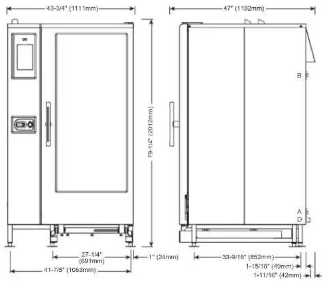
text_image
43-3/4" (1111mm) 79-1/4" (2012mm) 47" (1192mm) 27-1/4" (691mm) 41-7/8" (1063mm) 1" (24mm) 53-9/15" (852mm) 1-15/16" (49mm) 1-11/16" (42mm)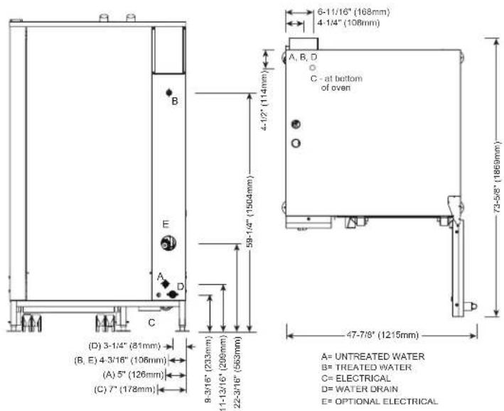
text_image
6-11/16" (108mm) 4-1/4" (108mm) A, B, D C - at bottom of oven 73-58" (1869mm) 47-7/8" (1215mm) A= UNTREATED WATER B= TREATED WATER C= ELECTRICAL D= WATER DRAIN E= OPTIONAL ELECTRICAL 4-1/2" (114mm) 59-1/4" (1504mm) 8-3/16" (233mm) 11-12/16" (209mm) 22-3/16" (563mm) (D) 3-1/4" (81mm) (B, E) 4-3/16" (106mm) (A) 5" (126mm) (C) 7" (178mm)

CE EAC IP X5
| WATER REQUIREMENTS | WATER QUALITY STANDARDS | |||||||
| TWO (2) COLD WATER INLETS - DRINKING QUALITYONE (1) TREATED WATER INLET: 3/4" NPT* Can manifold off ofONE (1) UNTREATED WATER INLET: 3/4" NPT* one 3/4" lineLINE PRESSURE: 30 psi minimum dynamic and 90 psi maximum static (200 to 600 kPa)WATER DRAIN: 1-1/2" (40mm) CONNECTION WITH A VERTICAL VENT TO EXTEND ABOVE THE EXHAUST VENT.MATERIALS MUST WITHSTAND TEMPERATURES UP TO 200°F (93°C). | It is the sole responsibility of the owner/operator/purchaser of this equipment to verify that the incoming water supply is comprehensively tested and if required, a means of "water treatment" provided that would meet compliance requirements with the published water quality standards shown below.Non-compliance with these minimum standards will potentially damage this equipment and/or components and void the original equipment manufacturer's warranty. Alto-Shaam recommends using OptiPure® [www.optipurewater.com] products to properly treat your water.Contaminant Inlet Water RequirementsFree Chlorine Less than 0.1 ppm (mg/L)Hardness 30-70 ppmChloride Less than 30 ppm (mg/L)pH 7.0 to 8.5Silica Less than 12 ppm (mg/L)Total Dissolved Solids (tds) 50-125 ppm | |||||||
| CLEARANCE REQUIREMENTS | ||||||||
| LEFT: 0" (0mm) | 18" (457mm) RECOMMENDED SERVICE ACCESS | |||||||
| RIGHT: 0" (0mm) NON-COMBUSTIBLE SURFACES 2" (51mm) DOOR SWING OR COMBUSTIBLE SURFACES | ||||||||
| TOP: 20" (508mm) FOR AIR MOVEMENT | ||||||||
| BACK: 4" (102mm)4-5/16" (109mm) OPTIONAL PLUMBING KIT | BOTTOM: 5-1/8" (130mm)FOR LEGS, AIR INTAKE | |||||||
| INSTALLATION REQUIREMENTS | ||||||||
| · Oven must be installed level. · Hood installation is required.· Water supply shut-off valve and back-flow preventer when required by local code. | ||||||||
| ELECTRICAL (NO CORD, NO PLUG, DEDICATED CIRCUIT REQUIRED) | ||||||||
| MODEL VOL TAGE PH HZ AMPS KW BREAKER AWG CONNECTION | ||||||||
| CTC20-20E | 208-240 3 50/60 137.6-158.8 49.6-66 150-175 4/0 L1, L2, L3, G | |||||||
| 380-415 3 50/60 84.2-91.7 56.4-66 100 1-1/0 L1, L2, L3, N, G | L1, L2, L3, G | |||||||
| 440-480 3* 50/60 72.7-79.4 56.5-66 80 2-1 L1, L2, L3, G | L1, L2, L3, N, G | |||||||
*ELECTRICAL SERVICE CHARGE APPLIES
| WEIGHT | SHIP DIMENSIONS | PAN CAPACITY | |||||
| NET | 1100 lbs est | 499 kg | (L x W x H) 53" x 53" x 87** | FULL-SIZE: | 20" x 12" x 2-1/2" | Forty (40) | PRODUCT MAXIMUM: 480 lb (218 kg) |
| SHIP | 1157 lbs* | 525 kg* | (1346 x 1346 x 2210mm)* | GN 1/1: | 530 x 325 x 65mm | Forty (40) | VOLUME MAXIMUM: 300 quarts (380 liters) |
| *DOMESTIC GROUND SHIPPING INFORMATION. CONTACT FACTORY FOR EXPORT WEIGHT AND DIMENSIONS. | GN 2/1: | 650 x 530 x 65mm | Twenty (20) | **ON WIRE SHELVES ONLY. ADDITIONAL WIRE SHELVES REQUIRED FOR MAXIMUM CAPACITY | |||
| *FULL-SIZE SHEET: | 18" x 26" x 1" | Twenty (20) | |||||
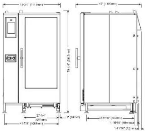
text_image
43-34" (111mm) 47" (118mm) 27-1/4" (691mm) 41-7/8" (1063mm) 1" (34mm) 33-6/18" (502mm) 1-19/15" (48mm) 1-11/16" (42mm)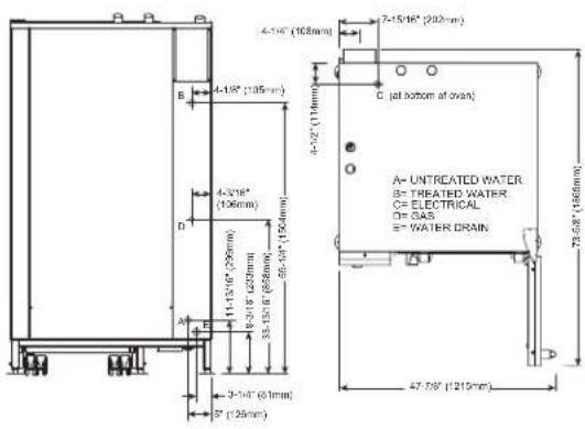
text_image
4-15" (108mm) 7-15/16" (200mm) 4-3/16" (106mm) 4-1/2" (119mm) C (at bottom of oven) A- UNTREATED WATER B- TREATED WATER C= ELECTRICAL D= GAS E= WATER DRAIN 3-3/16" (61mm) 3" (129mm) 47-7/8" (215mm)


| WATER REQUIREMENTS | WATER QUALITY STANDARDS | ||
| TWO (2) COLD WATER INLETS - DRINKING QUALITYONE (1) TREATED WATER INLET: 3/4" NPT* * Can manifold off ofONE (1) UNTREATED WATER INLET: 3/4" NPT* one 3/4" lineLINE PRESSURE: 30 psi minimum dynamic and 90 psi maximum static (200 to 600 kPa)WATER DRAIN: 1-1/2" (40mm) CONNECTION WITH A VERTICAL VENT TO EXTEND ABOVE THE EXHAUST VENT.MATERIALS MUST WITHSTAND TEMPERATURES UP TO 200°F (93°C). | It is the sole responsibility of the owner/operator/purchaser of this equipment to verify that the incoming water supply is comprehensively tested and if required, a means of "water treatment" provided that would meet compliance requirements with the published water quality standards shown below.Non-compliance with these minimum standards will potentially damage this equipment and/or components and void the original equipment manufacturer's warranty. Alto-Shaam recommends using OptiPure®[www.optipurewater.com] products to properly treat your water.Contaminant Inlet Water RequirementsFree Chlorine Less than 0.1 ppm (mg/L)Hardness 30-70 ppmChloride Less than 30 ppm (mg/L)pH 7.0 to 8.5Silica Less than 12 ppm (mg/L)Total Dissolved Solids (tds) 50-125 ppm | ||
| CLEARANCE REQUIREMENTS | |||
| LEFT: 0" (0mm) | 18" (457mm) RECOMMENDED SERVICE ACCESS | ||
| RIGHT: 0" (0mm) NON-COMBUSTIBLE SURFACES | 2" (51mm) DOOR SWING OR COMBUSTIBLE SURFACES | ||
| TOP: 20" (508mm) FOR AIR MOVEMENT | |||
| BACK: 4" (102mm)4-5/16" (109mm) OPTIONAL PLUMBING KIT | BOTTOM: 5-1/8" (130mm)FOR LEGS, AIR INTAKE | ||
| INSTALLATION REQUIREMENTS | |||
| · Oven must be installed level. · Hood installation is required.· Water supply shut-off valve and back-flow preventer when required by local code. | |||
| GAS REQUIREMENTS (GAS TYPE MUST BE SPECIFIED ON ORDER) | ||||||||||||
| HOOK-UP: 3/4" NPT | ||||||||||||
| RATED THERMAL LOAD CONNECTED PRESURE | ||||||||||||
| NORTH AMERICA INTERNATIONAL NORTH AMERICA INTERNATIONAL | ||||||||||||
| Natural Gas/Propane G20, G25, G31 Natural Gas Propane | G20 20mbar | |||||||||||
| Gross Heating Value (HHV) Net 266,000 Btu / hr | Heating Value (LHV) Minimum: 572.0 kW | 5" W.C. dynamic Minimum: 9" W.C. Maximum: 14" W.C. static | dynamicMaximum: 14" W.C. static | G25 20mbarG31 30mbar | ||||||||
| ELECTRICAL - CTP20-20G (DEDICATED CIRCUIT REQUIRED) | WITH COMBISMOKER® OPTION | |||||||||||
| VOLTAGE | PH | HZ | AWG | CONNECTIONno cord, no plug | AMPS | BREAKER | kW | CONNECTIONno cord, no plug | AMPS | BREAKER kW | ||
| →→ | 120 | 1 | 60 | 14 | L1, N, G | 13.6 | 20 | 1.7 | L1, N, G | 18.4 | 25 | 2.3 |
| →→ | 208 – 240 | 1+ | 50/60 | 14 | L1, L2/N, G | 9.6 – 8.4 | 15 | 2.0 | L1, L2/N, G | 12.1 – 11.3 | 15 | 2.5 – 2.7 |
| →→ | 208 – 240 | 3 | 50/60 | 14 | L1, L2, L3, G | 9.6 – 8.4 | 15 | 2.0 | L1, L2, L3, G | 12.1 – 11.3 | 15 | 2.5 – 2.7 |
| →→ | 380 – 415 | 3 | 50/60 | 14 | L1, L2, L3, N, G | 9.2 – 8.4 | 15 | 2.0 | L1, L2, L3, N, G | 11.8 – 11.3 | 15 | 2.6 – 2.7 |
NORTH AMERICA VOLTAGE CHOICE GROUND FAULT OR RESIDUAL CURRENT PROTECTION DEVICE MUST ACCOMMODATE A LEAKAGE CURRENT OF 20mA INTERNATIONAL VOLTAGE CHOICE ELECTRICAL SERVICE CHARGE APPLIES
| WEIGHT | SHIP DIMENSIONS | PAN CAPACITY | ||||
| NET | 1100 lbs est 499 kg | (L x W x H) 53" x 53" x 87"* | FULL-SIZE: | 20" x 12" x 2-1/2" Forty (40) | PRODUCT MAXIMUM: 480 lb (218 kg) | |
| SHIP | 1236 lbs* 561 kg* | (1346 x 1346 x 2210mm)* | GN 1/1: | 530 x 325 x 65mm | Forty (40) | VOLUME MAXIMUM: 300 quarts (380 liters) |
| ^DOMESTIC GROUND SHIPPING INFORMATION, CONTACT FACTORY FOR EXPORT WEIGHT AND DIMENSIONS. | GN 2/1: | 650 x 530 x 65mm | Twenty (20) | **ON WIRE SHELVES ONLY, ADDITIONAL WIRE SHELVES REQUIRED FOR MAXIMUM CAPACITY | ||
| **FULL-SIZE SHEET: | 18" x 26" x 1" | Twenty (20) | ||||
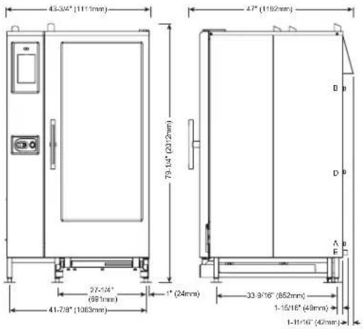
text_image
43.3/4" (111.1mm) 79.1/4" (201.2mm) 27.5/4" (89.1mm) 41.7/8" (108.9mm) 1" (24mm) 33.9/16" (852mm) 1-15/16" (49mm) 1-11/16" (42mm)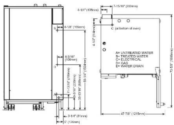
text_image
4-1/8" (105mm) 4-3/16" (106mm) 33-13/16" (850mm) 59-12" (1534mm) 4-1/4" (108mm) 7-15/16" (209mm) C (at bottom of oven) A= UNTREATED WATER B= TREATED WATER C= ELECTRICAL D= GAS E= WATER DRAIN 75 58" (1086mm) 47 7/8" (1215mm) 3-1/4" (81mm) B' (126mm)

CE EAC IP X5
WATER REQUIREMENTS
| TWO (2) COLD WATER INLETS - DRINKING QUALITYONE (1) TREATED WATER INLET: 3/4" NPT* · Can manifold off ofONE (1) UNTREATED WATER INLET: 3/4" NPT* one 3/4" lineLINE PRESSURE: 30 psi minimum dynamic and 90 psi maximum static (200 to 600 kPa)WATER DRAIN: 1-1/2" (40mm) CONNECTION WITH A VERTICAL VENT TO EXTEND ABOVE THE EXHAUST VENT.MATERIALS MUST WITHSTAND TEMPERATURES UP TO 200°F (93°C). | |
| CLEARANCE REQUIREMENTS | |
| LEFT: 0" (0mm) | 18" (457mm) RECOMMENDED SERVICE ACCESS |
| RIGHT: 0" (0mm) NON-COMBUSTIBLE SURFACES | 2" (51mm) DOOR SWING ORCOMBUSTIBLE SURFACES |
| TOP: 20" (508mm) FOR AIR MOVEMENT | |
| BACK: 4" (102mm)4-5/16" (109mm) OPTIONAL PLUMBING KIT | BOTTOM: 5-1/8" (130mm)FOR LEGS, AIR INTAKE |
| INSTALLATION REQUIREMENTS | |
| · Oven must be installed level. · Hood installation is required.· Water supply shut-off valve and back-flow preventer when required by local code. | |
GAS REQUIREMENTS (GAS TYPE MUST BE SPECIFIED ON ORDER)
| HOOK-UP: 3/4" NPT | |||||||||
| RATED THERMAL LOAD CONNECTED PRESSURE | |||||||||
| NORTH AMERICA INTERNATIONAL NORTH AMERICA INTERNATIONAL | |||||||||
| Natural Gas/Propane G20, G25, G31 Natural Gas Propane | G20 20mbar | ||||||||
| Gross Heating Value (HHV) Net 242,000 Btu / hr | Heating Value (LHV) Minimum: 5.5" W.C. dynamic Minimum: 9" W.C. dynamic Maximum: 14" W.C. static | G25 20mbar | |||||||
| G31 30mbar | |||||||||
| ELECTRICAL - CTC20-20G (DEDICATED CIRCUIT REQUIRED) | |||||||||
| VOLTAGE | PH | HZ | AWG | CONNECTION | AMPS | BREAKER | kW | ||
| →→→ | 120 | 1 | 60 | 12 | L1, N, G - no cord, no plug | 13.0 | 20 | 1.7 | |
| →→ | 208 – 240 | 3 | 50/60 | 14 | L1, L2, L3, G - no cord, no plug | 9.6 – 8.4 | 15 | 2.0 | |
| →→ | 380 – 415 | 3 | 50/60 | 14 | L1, L2, L3, N, G - no cord, no plug | 9.2 – 8.4 | 15 | 2.0 | |
NORTH AMERICA VOLTAGE CHOICE GROUND FAULT OR RESIDUAL CURRENT PROTECTION DEVICE MUST ACCOMMODATE A LEAKAGE CURRENT OF 20mA INTERNATIONAL VOLTAGE CHOICE
| WEIGHT | SHIP DIMENSIONS | PAN CAPACITY | ||||
| NET | 1100 lbs est | 499 kg | (L x W x H) 53" x 53" x 87"* | FULL-SIZE: 20" x 12" x 2-1/2" | Forty (40) | PRODUCT MAXIMUM: 480 lb (218 kg) |
| SHIP | 1236 lbs* | 561 kg* | (1346 x 1346 x 2210mm)* | GN 1/1: 530 x 325 x 65mm | Forty (40) | VOLUME MAXIMUM: 300 quarts (380 liters) |
| *DOMESTIC GROUND SHIPPING INFORMATION. CONTACT FACTORY FOR EXPORT WEIGHT AND DIMENSIONS. | GN 2/1: 650 x 530 x 65mm | Twenty (20) | **ON WIRE SHELVES ONLY, ADDITIONAL WIRE SHELVES REQUIRED FOR MAXIMUM CAPACITY | |||
| **FULL-SIZE SHEET: 18" x 26" x 1" | Twenty (20) | |||||
SITE INSTALLATION
WARNING

To prevent SERIOUS INJURY, DEATH, or PROPERTY DAMAGE:
• Always keep appliance on top of a pallet when using a fork lift or a pallet lift truck to move appliance.
• Always use a sufficient number of trained and experienced workers to place the appliance on floor, stand, or counter.
INSTALLATION
To ensure proper operation, the installation of this oven must be completed by qualified technicians in accordance with the instructions provided in this manual. Failure to follow the instructions provided may result in damage to the oven, building, or cause personal injury to personnel.
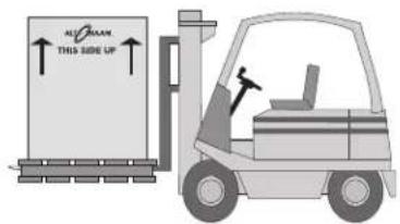
text_image
ALO OAKM THIS SIDE UP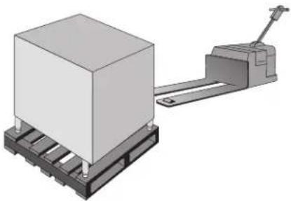
natural_image
3D rendering of a pallet jack and a block on a base (no text or symbols visible)NOTICE: To prevent PROPERTY DAMAGE: Check the dimensions of the doorways and aisles before attempting to move the oven and pallet to the installation site.
Do not tilt the oven. Transport the oven in an upright and level position only.
Slide the preheat strip into place before using a forklift or pallet jack in between the trolley guides to avoid damaging the preheat strip when lifting.
text_image
components protrude below ovenLIFTING INSTRUCTIONS
Remove banding before lifting. Lift the unit from the front only, never from the side.
Adjust the forks so that they do not damage any of the components under the unit. Note that the control side of the oven is the heaviest portion. Lift the unit just high enough to remove the wooden pallet. Lower the unit as close to the floor as possible and no more than 2" (50mm) above the floor. Secure hoses and dangling cords to avoid tangling or damage. When moving the unit, drive slowly, keep it low to the ground, and use extreme caution.
DEPTH OF FORKS IS CRITICAL FOR UNITS
EQUIPPED WITH GREASE COLLECTION TO AVOID
DAMAGING THE PUMP
natural_image
3D rendering of a laboratory instrument with control panel and tubing (no visible text or symbols)Grease Collection Pump
INSTALLATION
SITE INSTALLATION
4" (102mm) FOR PLUMBING
4-5/16" (109mm) WITH OPTIONAL PLUMBING KIT

text_image
18" (457mm) SERVICE ACCESS0" (0mm) FROM NON-COMBUSTIBLE SURFACES 2" (51mm) FROM COMBUSTIBLE SURFACES 2" (51mm) FOR DOOR SWING
| MINIMUM CLEARANCE REQUIREMENTS | |
| LEFT SIDE18" (457mm) | 0" (0mm) MINIMUMRECOMMENDED SERVICE ACCESS |
| RIGHT SIDE2" (51mm2" (51mm) | 0" (0mm) FROM NON-COMBUSTIBLE SURFACES) FROM COMBUSTIBLE SURFACES) FOR DOOR SWING |
| BACK4-5/16" (109mm) | 4" (102mm) FOR PLUMBINGFOR OPTIONAL PLUMBING KIT |
| TOP | 20" (508mm) FOR AIR MOVEMENT |
| BOTTOM 5-1/8" (45mm) | 7mm)FOR LEGS AND UNOBSTRUCTED AIR INTAKE |
NOTICE: • A minimum distance of 18" (457mm) is strongly recommended for service access. If adequate service clearance is not provided, it will be necessary to disconnect the gas, water, and drain to move the oven with a fork lift for service access. Service charges in connection with inadequate service access is not covered under warranty.
- Do not install a stacked combination directly over a drain. Steam rising up out of the drain will adversely affect operation, hamper cooling air circulation, and may damage electrical and electronic components. Failure to do so will void the warranty. A single oven installed on a stand with solid surface bottom shelf can be positioned over a drain since the solid surface will block the rising steam.
POSITIONING ON SITE - COUNTERTOP
Place the oven on a stable, non-combustible level horizontal surface. Use the adjustable feet to overcome an uneven floor and ensure that the unit is level.
It is strongly recommended that table top models be mounted on a factory supplied stand or a stand that is stable, open, and level. The adjustable oven legs should be extended beyond the depth of the positioning ring to allow for leveling after the oven has been placed on the stand.
Each of the legs on the stand and the oven can be adjusted 2" (51mm) up or down.
Level the oven from front-to-back and side-to-side by means of the adjustable legs. Components within the oven condenser tank are sensitive to pitch and can be damaged. The tolerance to level is +/- .125"
If this tolerance range is not achievable, the floor must be repaired to obtain level.
text_image
6.16[156.50] (MAX HEIGHT) 3.66[93.00] (MIN HEIGHT) LEG DIMENSIONS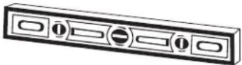
Positioning Rings
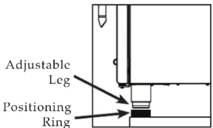
text_image
Adjustable Leg Positioning Ring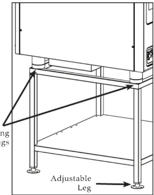
text_image
ng gs Adjustable LegINSTALLATION
SITE INSTALLATION
POSITIONING ON SITE — 20-10 & 20-20 MODELS
Place the oven on a stable, non-combustible level horizontal surface. Use the adjustable feet to overcome an uneven floor and ensure that the unit is level.
-
Once the unit has been positioned properly beneath a ventilation hood system, adjust the four outside feet located on the outside corners of the base frame. Begin with a 32mm (1.25") height (illustration 1) leveling the oven from side-to-side and front-to-back (illustration 2).
-
Roll the trolley into the oven and check the overall fit of the trolley. Close the door and check fit. Make adjustments as needed.
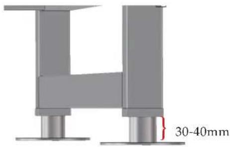
text_image
30-40mmIllustration 1
Illustration 2

natural_image
Two views of a stainless steel industrial enclosure with yellow safety tags and blue control panels (no text or symbols visible)
natural_image
Pure mechanical assembly diagram showing bidirectional red arrows indicating movement, no text or symbols presentNOTICE: Adjustable measurements are from the top of the leg flange to the bottom of the leg square frame (see illustration 1). If measurements exceed 40mm in height or trolley is not on a level and stable horizontal floor, the following may occur:
- Improper sealing of the door sweep gasket to the trolley plate, or heat strip.
• Trolley may not fit properly.
INSTALLATION
OPTIONS & ACCESSORIES
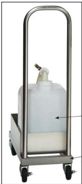
natural_image
Metallic industrial cart with a white plastic container and water dispenser, no visible text or symbols
text_image
AUTO SHAAM WHEE MMS MASCENT WORK DESIGNED FOR THE THERMOSTABLE CHEDDER (No. 013-2144) SUSKMELONIC CHEMICAL CHEMICAL SUSKMELONIC CHEMICAL CHEMICAL NO. 013-2144 SUSKMELONIC CHEMICAL CHEMICAL SUSKMELONIC CHEMICAL CHEMICAL SUSKMELONIC CHEMICAL CHEMICAL SUSKMELONIC CHEMICAL CHEMICAL SUSKMELONIC CHEMICAL CHEMICAL SUSKMELONIC CHEMICAL CHEMICAL SUSKMELONIC CHEMICAL CHEMICAL SUSKMELONIC CHEMICAL CHEMICAL SUSKMELONIC CHEHOMO SUSKMELONIC CHEHOMO SUSKMELONIC CHEHOMO SUSKMELONIC CHEHOMO SUSKMELONIC CHEHOMO SUSKMELONIC CHEHOMO SUSKMELONIC CHEHOMO SUSKMELONIC CHEHOMO SUSKMELONIC CHEHOMO SUSKMELONIC CHEHOMO□ SCALE FREE™
CITRUS BASED, NON-CORROSIVE
DELIMING PRODUCT
CE-27889
POULTRY GREASE
COLLECTION CONTAINER
15" x 9-3/4" x 9-3/4"
(381×248×248mm)
5014846
□ MOBILE GREASE
COLLECTION CART
37" x 11-3/16" X 28-1/2"
(940×284×724mm)
5014542
natural_image
Close-up of baked goods inside a metal cage (no visible text or symbols)□ FRY BASKET
12" × 20"
(325mm×530mm)
BS-26730
natural_image
Metal grid structure with vertical and horizontal lines, no text or symbols visible
natural_image
Six golden-brown baked food items arranged on a black bamboo mat (no text or symbols visible)□ GRILLING GRATE
12" × 20"
(325mm×530mm)
SH-26731
natural_image
Box filled with dried herbal material and scattered dried herbs (no text or symbols visible)WOOD CHIPSSHELF, STAINLESS S'
SH-22473 SHOWN
| CombiClean® CombiTabsTM — SPECIALLY FORMULATED FOR CTP/CTC COMBITHERM OVENS90 (18 GRAM) WATER SOLUBLE TABLETS EACH CONTAINER, SOLD IN BOXES OF TWO (2) | CE-36354 |
| Combitherm® Cleaning Liquid — SPECIALLY FORMULATED FOR COMBITHERM OVENSTWELVE (12) CONTAINERS/CASE, 1 QUART (C. 1 LITER) EACH [SPECIAL HANDLING REQUIRED] | CE-24750 |
| Liquid Cleaner — APPROVED FOR COMBITHERM OVENS EQUIPPED WITH THE OPTIONALAUTOMATIC LIQUID CLEANING SYSTEM | CE-36457 |
| Gas Line Quick Disconnect | CR-33543 |
| Grease Collection Pan WITH DRAIN (NOT NEEDED FOR GREASE COLLECTION SYSTEM) | |
| 6-10, 10-10, 20-10 — 1-1/2" (38mm) DEEP | 5003463 |
| 7-20, 10-20, 20-20 — 1-1/2" (38mm) DEEP | 4758 |
| 7-20, 10-20, 20-20 — 2-3/4" (70mm) DEEP | 14475 |
| Probe, Sous Vide | PR-36576 |
| Shelf, Stainless Steel Wire | |
| 7-20, 10-20 SH-22584 | |
| 6-10, 10-10, 20-10 SH-2903 | |
| 20-20 SH-22473 | |
| Smoker Box | 5021859 |
| Wood Chips — BULK PACK 20 LB (9 KG) | |
| APPLE | WC-22543 |
| CHERRY | WC-22541 |
| HICKORY | WC-2829 |
| MAPLE | WC-22545 |
INSTALLATION
ELECTRICAL SAFETY REGULATIONS

CAUTION

Power source must match voltage identified on appliance rating tag. The rating tag provides essential technical information required for any appliance installation, maintenance or repairs. Do not remove, damage or modify the rating tag.
WARNING

To prevent SERIOUS INJURY, DEATH, or PROPERTY DAMAGE:
All electrical connections must be made by a qualified and trained service technician in accordance with applicable electrical codes.

This appliance MUST be adequately grounded in accordance with local electrical codes or, in the absence of local codes, with the current edition of the National Electrical Code ANSI/NFPA No. 70. In Canada, all electrical connections are to be made in accordance with CSA C22.1, Canadian Electrical Code Part 1 or local codes.
DANGER

Appliances with no cord provided by factory must be equipped with a cord of sufficient length to permit the appliance to be moved for cleaning.

To prevent SERIOUS INJURY, DEATH, or PROPERTY DAMAGE: all electrical connections must be made by a qualified service technician in accordance with applicable electrical codes.
Always use the correct AWG wire size based on the electrical requirements for the appliance.
WARNING

Improper installation, alteration, adjustment, service, cleaning, or maintenance could result in PROPERTY DAMAGE, SEVERE INJURY, or DEATH.
Read and understand the installation, operating and maintenance instructions thoroughly before installing, servicing, or operating this equipment.

WARNING

To prevent serious injury, death, or property damage, always disconnect appliance from power source before cleaning or servicing.
INSTALLATION
ELECTRICAL CONNECTION FOR GAS MODELS
- An electrical wiring diagram is located behind the control panel on the left side of the oven. This appliance must be branch circuit protected with proper ampacities, in accordance with the wiring diagram.
- For 1-phase applications, the ground fault or residual current protection device must accommodate a leakage current of 20 mA.
- Wire size for the main incoming power to the unit must match the minimum size listed in the specifications applicable to the specific oven model. For supply connections, locate the wire size posted on the label located on the electrical control box cover, behind the service panel.
- Before operating the oven, check all cable connections and electrical terminal connections in the electrical connection area for tightness since connections can loosen during transport.
NOTICE: Check motor rotation on the Combitherm® CT Classic CTC model line. Arrows on the motor housing indicate proper rotation.
After both water and electrical connections have been completed on all Combitherm model types, operate the oven in any cooking mode for a period of 15 minutes. Recheck the main power connections at the terminal block, cable connections, and electrical terminal connections to make certain they remain tight.
WARNING

ELECTRICAL GROUNDING INSTRUCTIONS:
This appliance may be equipped with a three-pronged (grounding) plug for your protection against shock hazard and should be plugged directly into a properly grounded three-prong receptacle.
NEVER cut or remove the grounding prong from this plug. Removing the grounding prong may result in serious injury, death or property damage.
AVERTISSEMENT
For CE approved appliances: To prevent an electrical shock hazard between the appliance and other appliances or metal parts in close vicinity, an equalization-bonding stud is provided. An equalization bonding lead must be connected to this stud and the other appliances/metal parts to provide sufficient protection against potential difference. The terminal is marked with the following symbol.
INSTALLATION
ELECTRICAL CONNECTION FOR ELECTRIC MODELS
- An electrical wiring diagram is located behind the control panel on the left side of the oven. This appliance must be branch circuit protected with proper ampacities, in accordance with the wiring diagram.
- Wire size for the main incoming power to the unit must match the minimum size listed in the specifications applicable to the specific oven model. For supply connections, locate the wire size posted on the label located on the electrical control box cover, behind the service panel.
- Before operating the oven, check all cable connections and electrical terminal connections in the electrical connection area for tightness since connections can loosen during transport.
NOTICE: Check motor rotation on the Combitherm® CT Classic CTC model line. Arrows on the motor housing indicate proper rotation.
After both water and electrical connections have been completed on all Combitherm model types, operate the oven in any cooking mode for a period of 15 minutes. Recheck the main power connections at the terminal block, cable connections, and electrical terminal connections to make certain they remain tight.
Hard wired models:
Hard wired models must be equipped with a country certified external allpole disconnection switch with sufficient contact separation.
If a power cord is used for the connection of the product an oil resistant cord like H05RN or H07RN or equivalent must be used.
380-415V:

For CE approved appliances: To prevent an electrical shock hazard between the appliance and other appliances or metal parts in close vicinity, an equalization-bonding stud is provided. An equalization bonding lead must be connected to this stud and the other appliances/metal parts to provide sufficient protection against potential difference. The terminal is marked with the following symbol.

INSTALLATION
ELECTRICAL CONNECTION
Examples shown.
Not all 3-phase units require a neutral.
3-PHASE ELECTRICALWITH NEUTRAL

text_image
GroundL1
L2
L3
Neutral*

1-PHASE ELECTRICAL WITHOUT NEUTRAL
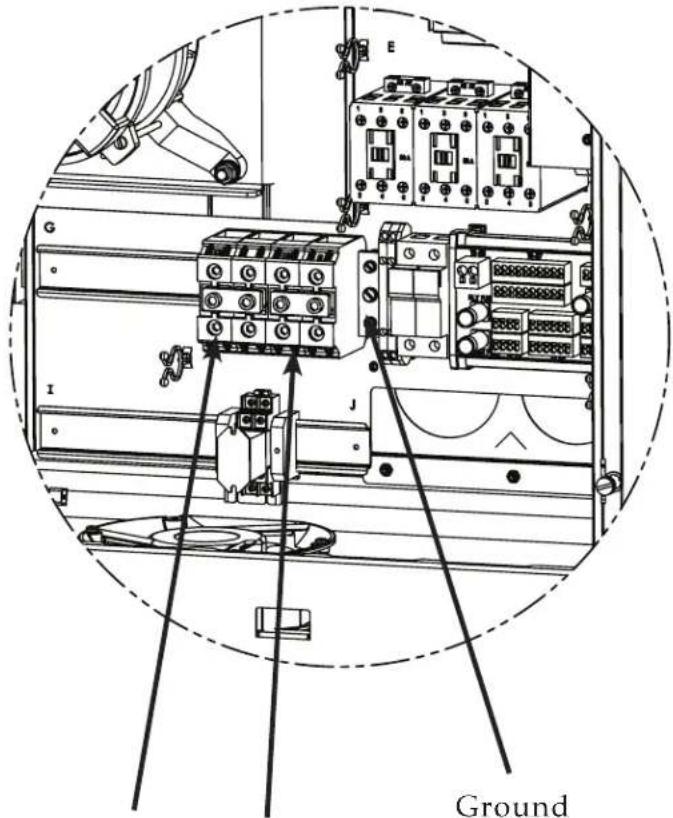
text_image
E G I J GroundL1
L2/Neutral*
*Neutral applies only to 380/415V models
INSTALLATION
ELECTRICAL KIT INSTALLATION - 50 Hz
International Applications
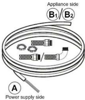
text_image
Appliance side B₁/B₂ Power supply side1
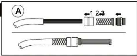
text_image
A 1 2 3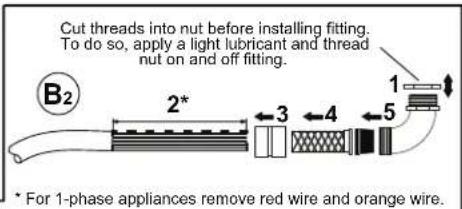
text_image
Cut threads into nut before installing fitting. To do so, apply a light lubricant and thread nut on and off fitting. B2 2* 3 4 5 1 * For 1-phase appliances remove red wire and orange wire.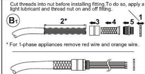
text_image
Cut threads into nut before installing fitting. To do so, apply a light lubricant and thread nut on and off fitting. B1 2* 3 4 5 1 * For 1-phase appliances remove red wire and orange wire.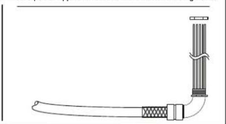
natural_image
Simple line drawing of a mechanical or electrical component with no text or symbols3
Discard the cover plate if applicable.
Position and attach the support plate (x).
2
Remove enough cable covering so that wires reach the terminal strip. Depending on the application, install the straight or elbow fitting to the cable.

flowchart
graph TD
    A["Initial material"] --> B{Recycle}
    B --> C["Recycle Bin"]
    C --> D["Recycle Bin 1"]
    D --> E["Recycle Bin 2"]
    E --> F["Recycle Bin 3"]
    F --> G["Recycle Bin 4"]
    G --> H["Recycle Bin 5"]
    H --> I["Recycle Bin 6"]
    I --> J["Recycle Bin 7"]
    J --> K["Recycle Bin 8"]
    K --> L["Recycle Bin 9"]
    L --> M["Recycle Bin 10"]
    M --> N["Recycle Bin 11"]
    N --> O["Recycle Bin 12"]
    O --> P["Recycle Bin 13"]
    P --> Q["Recycle Bin 14"]
    Q --> R["Recycle Bin 15"]
    R --> S["Recycle Bin 16"]
    S --> T["Recycle Bin 17"]
    T --> U["Recycle Bin 18"]
    U --> V["Recycle Bin 19"]
    V --> W["Recycle Bin 20"]
4
Install the fitting/wiring to the appliance. 1-1/2" NPT and smaller bushings through the bottom, all others through the back.
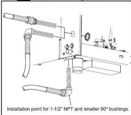
text_image
Installation point for 1-1/2" NPT and smaller 90° bushings.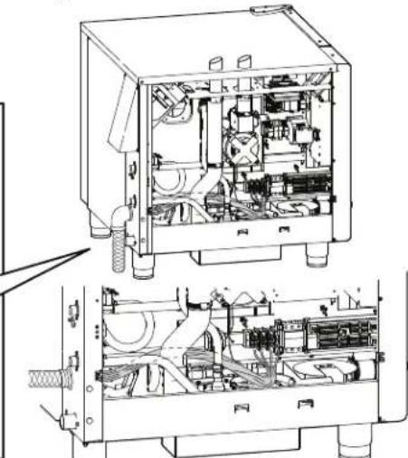
natural_image
Technical line drawing of an internal mechanical device with internal components and housing (no text or symbols)5
Route the wires.
Keep wires away from hot surfaces such as: water tank, drain pipe, motor, edges of sheet metal, vent pipes, or other appliances.
NOTICE
For 1-phase, gas applications, the ground fault or residual current protection device must accommodate a leakage current of 20 mA.
6
Strip the wires, then connect them to the terminal strip. Note: Illustrations are representative only. Your appliance may vary.
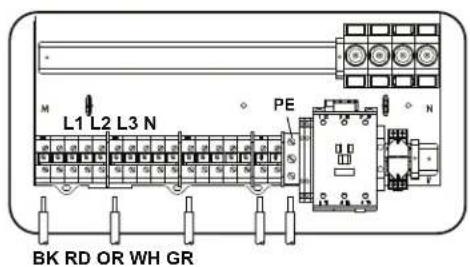
text_image
L1 L2 L3 N PE BK RD OR WH GR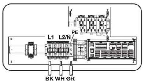
text_image
L1 L2/N PE BK WH GR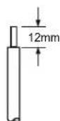
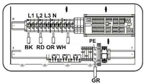
text_image
L1 L2 L3 N BK RD OR WH PE GRINSTALLATION
ELECTRICAL KIT INSTALLATION - 60 Hz
Applications for the Americas
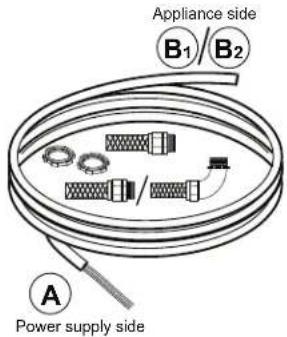
text_image
Appliance side B₁/B₂ Power supply side1

text_image
A 1 2 3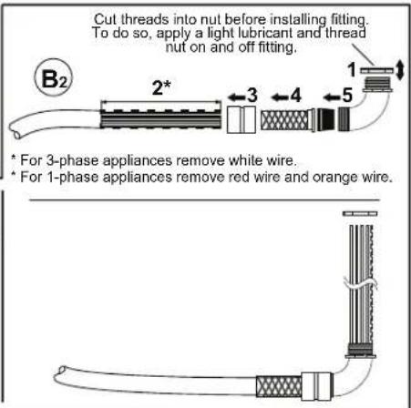
text_image
Cut threads into nut before installing fitting. To do so, apply a light lubricant and thread nut on and off fitting. B2 1 2* 3 4 5 * For 3-phase appliances remove white wire. * For 1-phase appliances remove red wire and orange wire.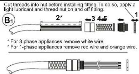
text_image
Cut threads into nut before installing fitting. To do so, apply a light lubricant and thread nut on and off fitting. B1 2* 3 4.5 1 * For 3-phase appliances remove white wire. * For 1-phase appliances remove red wire and orange wire.2
Remove enough cable covering so that wires reach the terminal strip. Depending on the application, install the straight or elbow fitting to the cable.
3 Discard the cover plate if applicable. Position and attach the support plate (x).

flowchart
graph TD
    A["Initial Bag"] --> B["Recycle Bin"]
    B --> C["Add Material to Plastic Box"]
    C --> D["Recycle Bin"]
    D --> E["Add Material to Plastic Container"]
    E --> F["Final Bag"]
4
Install the fitting/wiring to the appliance.
1-1/2" NPT and smaller bushings through the bottom, all others through the back.
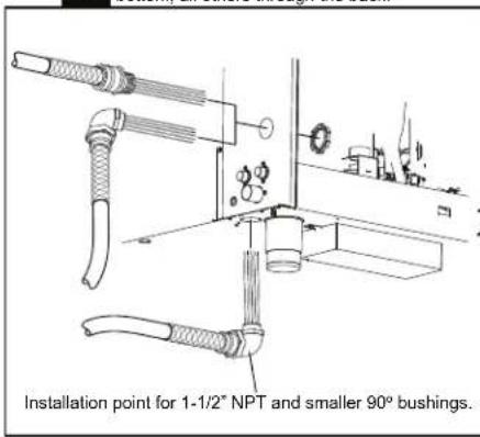
text_image
Installation point for 1-1/2" NPT and smaller 90° bushings.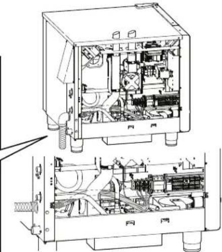
natural_image
Technical line drawing of an internal mechanical device with internal components and housing (no text or labels)5
Route the wires.
Keep wires away from hot surfaces such as: water tank, drain pipe, motor, edges of sheet metal, vent pipes, or other appliances.
NOTICE
For 1-phase, gas applications, the ground fault or residual current protection device must accommodate a leakage current of 20 mA.
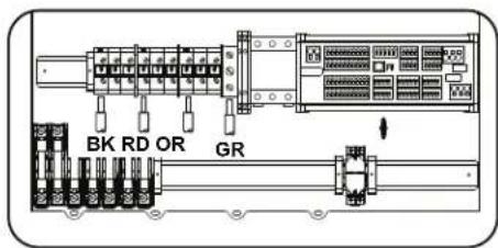
text_image
BK RD OR GR6
Strip the wires, then connect them to the terminal strip.
Note: Illustrations are representative only. Your appliance may vary.

text_image
L1 L2/N GND BK WH GR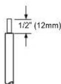
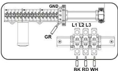
text_image
GND GR L1 L2 L3 BK RD WHVENTILATION REQUIREMENTS
REQUIREMENTS FOR GAS MODELS
WARNING

To prevent SERIOUS INJURY, DEATH, or PROPERTY DAMAGE:
Installation, air adjustment and/or service work must be in accordance with all local codes and must be performed by a trained service technician qualified to work on gas appliances.
- A single gas Combitherm oven requires a minimum of 28 CFM make-up air for both natural and propane gas. The bottom of the oven allows necessary air flow into the appliance necessary for gas combustion and must be kept clear at all times.

DO NOT obstruct or restrict ventilation nor the air flow required to support combustion.
- It is especially critical that gas supply piping and electrical support cord and/or receptacle be routed away from the path of the hot combustion fumes.
- Make certain the oven installation maintains adequate air ventilation to provide cooling for electrical and gas components. The area around the oven should be clear of any obstructions which might retard the flow of cooling air. Failure to observe this caution may result in damage to the components and will void the warranty.
- This oven cannot be direct vented.
- Install the oven under a ventilation hood meeting all applicable code requirements. Combustion fumes must be vented in accordance with local, state, or national codes.
NOTICE
Inadequate ventilation, or failure to ensure an adequate air flow may result in high ambient temperatures at the rear of the appliance. High ambient temperatures can cause the thermal-overload protection device on the blower motor to trip resulting in severe damage to the blower motor.
An adequate ventilation system is required for commercial cooking equipment. Information may be obtained by writing to the National Fire Protection Association, Batterymarch Park, Quincy, MA 02269. When writing refer to NFPA No. 96.
WARNING

DO NOT obstruct or block exhaust flues or attach any flue extension that may impede proper burner operation, restrict the exhaust fumes and cause negative backdraft or the appliance to shut down. Failure to do so may result in serious injury or death.
WARNING

Failure to properly vent this appliance may cause SERIOUS INJURY, DEATH, or PROPERTY DAMAGE. The formation of volatile substances may cause suffocation, equipment damage, operational problems and unsatisfactory cooking performance as a consequence of improper venting and is not covered by your warranty.
Ventilation hoods and exhaust systems shall be permitted to be used to vent appliances installed in commercial applications.
In accordance with NFPA 54 for the
Commonwealth of Massachusetts only:
Where automatically operated appliances are vented through a ventilation hood or exhaust system equipped with a damper or with a power means of exhaust, provisions shall be made to allow the flow of gas to the main burners only when the damper is open to a position to properly vent the appliance and when the power means of exhaust is in operation.
INSTALLATION
GAS SUPPLY & INSTALLATION
WARNING

To prevent SERIOUS INJURY or DEATH from fire or explosion:
Only connect the type of gas indicated on the identification nameplate. Your gas Combitherm® is equipped to operate using only the fuel type specified on the identification name plate. Should conversion from natural gas to propane or from propane to natural gas be desired, conversion parts must be ordered from Alto-Shaam. Conversions must be performed by an Alto-Shaam authorized service provider only. Always ensure the oven's nameplate reflects the intended fuel type for your oven.
Residential gas connections and hard-piped gas connections DO NOT meet NSF certifications and should NEVER be used with your Combitherm oven.
Please refer to model specifications for rated thermal loads and connected pressure requirements.
WARNING

To prevent SERIOUS PERSONAL INJURY, installation of this appliance must conform to local, state, and national codes; the current edition of the American National Standard Z223.1, National Fuel Gas Code, and all local municipal building codes. In Canada, installation must be in accordance with Standard CAN/CSA B 149.1 and Installation Codes - Gas Burning Appliances, and local codes.
NOTICE: Connection components not supplied by Alto-Shaam must comply with the regulations in force of the country of use.
Natural Cat Gas Type
| GR II2H3B/P 2H-G20-20mbar | ||
| CY II2H3B/P 2H-G20-20mbar | ||
| ES/FR/GB/IE/CH II2H3P | 2H-G20-20mbar | |
| AT II2H3B/P 2H-G20-20mbar | ||
| BE II2E(S)3B/P 2H-G20-20mbar | ||
| DE II2ELL3B/P 2E-G20/G25-20mbar | ||
| NL II2L3B/P 2L-G25-25mbar | ||
| Butane/Propane Mixture | Cat Gas Type | |
| GR II2H3B/P 3B/P-G30/G31-30mbar | ||
| CY II2H3B/P 3B/P-G30/G31-30mbar | ||
| ES/FR/GB/IE/CH II2H3P | 3P-G31-30mbar | |
| AT II2H3B/P 3B/P-G30/G31-50mbar | ||
| BE II2E(S)3P 3P-G31-30mbar | ||
| DE II2ELL3B/P 3B/P-G30/G31-50mbar | ||
| NL II2L3B/P 3B/P-G30/G31-30mbar | ||
| AUS/NZ | NGN 1.37 kPa | |
| AUS/NZ | LPG-X Propane 2.24 kPa | |
| Japan | Natural Gas 13A 1.96 kPa | |
| Japan | LPG - Propane 2.8 kPa |
SEDIMENT TRAP REQUIRED:
Where a sediment trap is not incorporated as part of the appliance, a sediment trap shall be installed downstream of the appliance shutoff valve as close to the inlet of the appliance as practical at the time of appliance installation. The sediment trap shall be either a tee fitting with a capped nipple in the bottom outlet, as illustrated below or another device recognized as an effective sediment trap.
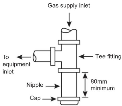
text_image
Gas supply inlet To equipment inlet Nipple Cap Tee fitting 80mm minimumINSTALLATION
GAS SUPPLY & INSTALLATION
WARNING

Improper installation, adjustment of burner pressures, alteration, service, maintenance, or use can cause carbon monoxide poisoning, explosion, fi re, electrical shock, or other conditions which may cause SERIOUS INJURY, DEATH or PROPERTY DAMAGE. Consult a qualified and trained installer, service agency, local gas supplier, or your distributor for information or assistance. The qualified and trained installer or agency must use only factory-authorized and listed kits or accessories when modifying this appliance.
INSTALLATION REQUIREMENTS
GAS CONNECTION: 3/4" NPT
For Europe, gas connection thread fittings should conform to EN ISO 228-1, or ISO 7-1, or shall have a compression fitting.
If the appliance has casters, a restraint system must be installed. See section Mobile Equipment Restraint, page 53.
NOTE: If a flexible gas line is used, it must be AGA approved, commercial type and at least 3/4" I.D. or comply to European Standard EN203.
HOOD INSTALLATION IS REQUIRED
After installation, burner and gas valve should be checked and adjusted by a qualified and trained Alto-Shaam technician for proper operation and validate CO2 levels. GAS VALVE MAY REQUIRE FIELD ADJUSTMENT ABOVE 2,000' (610m) AND IS NOT ADJUSTED AT THE FACTORY.
! WARNING

To prevent serious injury, death, or property damage, always disconnect appliance from power source before cleaning or servicing.
INSTALLATION
GAS SUPPLY & INSTALLATION
WARNING

To prevent SERIOUS INJURY, DEATH, or PROPERTY DAMAGE:
Installation, air adjustment and/or service work must be in accordance with all local codes and must be performed by a trained service technician qualified to work on gas appliances.
Remove any tape or compound residue on all external thread connections before proceeding. Use an approved gas pipe sealant at all external threaded connections,
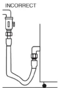
text_image
INCORRECT
text_image
CORRECTGas piping used on gas connections must avoid sharp bends that may restrict the flow of gas to the appliance. If the connected pressure exceeds 14.0" W.C. (3.5 kPa), a step-down regulator is required to be supplied by the owner/operator.
Close the individual manual shut-off valve to isolate the appliance from the gas supply piping system during any pressure testing at test pressures equal to or less than 1/2 psig. (3,4 kPa). The appliance and individual shut-off valve must be disconnected from the gas supply piping system during any pressure testing at pressures in excess of 1/2 psig. (3,4 kPa).
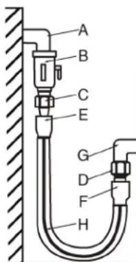
text_image
A B C E G D F HGAS INTAKE
A-G Installation elbow
B Ball Valve
C-D Three-piece union fitting (minimum 1 per installation)
E-F End connector for the flexible tube
H Marking line
WARNING

For your safety
DO NOT store or use gasoline or other flammable vapors or liquids in the vicinity of this or any other appliance.
AVERTISSEMENT

DO NOT spray aerosols in the vicinity of this appliance when in operation.
In the U.S.A., installation must conform to local codes or, in the absence of local codes, with the current edition of the National Fuel Gas Code, NFPA-54 and ANSI Z83.11a CSA 1.8a 2004 (or latest edition). In Canada, installation must be in accordance with local codes, CAN/CGA-B149.1, Installation for Natural Gas Burning Appliances and Equipment (latest edition) or CAN/CGAB149.2 Installation for Propane Burning Appliances and Equipment (latest edition). In Europe, installation must be in accordance with European Standard EN203.
The inlet supply line must be properly sized to accommodate all individual appliances simultaneously used on the same line but must never be smaller than 3/4" NPT.
CAUTION

To prevent INJURY or PROPERTY DAMAGE, make certain the area around the appliance is kept clear of combustible items.
INSTALLATION
GAS SUPPLY & INSTALLATION
WARNING

To prevent SERIOUS INJURY, DEATH, or PROPERTY DAMAGE:
Always use proper length pipes to avoid stress on the gas control manifold.
Always use an approved gas pipe sealant at all external threaded connections.
Always remove any tape or compound residue on all external thread connections before installing appliance.
The minimum size requirement for gas piping or a flexible connector is 3/4 - inch (19mm). For long runs of gas piping, the pipe diameter must conform to the tables in the National Fuel Gas Code, ANSI/NFPA Z223.1 or European Standard EN203.
A listed gas shut-off valve must be installed upstream of the appliance to shut off the gas supply during servicing. The shut-off valve should be accessible with the appliance in the normal installation position.
If the oven or the oven stand is supplied with casters, gas connection must be made with a flexible connector that complies with the Standard for Connectors for Movable Gas Appliances, ANSI Z21.69; or in Canada, Connectors for Movable Gas Appliances, CAN/CGA-6.16-M87. When using a flexible connector, a quick disconnect device must be used to comply with the Standard for Quick-Disconnect Devices for Gas Fuels, ANSI Z21.41; or in Canada, Quick Disconnect Devices for Use with Gas Fuels, CAN1-6.9 or European Standard EN203.
When a quick disconnect device and flexible connector are used, a restraining device must be installed to limit the movement of the appliance and prevent damage to the connector or quick disconnect. An example of a restraining device would consist of a 2000 pound test, stainless steel cable, attached to a structural member of the kitchen wall behind the oven. The means of attachment should consist of a quick connect snap so that the oven can be disconnected when the appliance must be moved away from the wall.
The other end of the cable should be permanently attached to the rear frame of the oven. The cable should be of sufficient length so that no strain is ever placed on the flexible gas connector in the event of accidental movement of the oven without properly disconnecting the gas connector. The flexible connector should be routed to form a downward "U" loop between the building gas supply and the permanent attachment at the rear of the oven.
The routing of the flexible connector must not run along the side of the exhaust stacks or cross the exhaust stacks. Oven temperatures achieved during operation are too hot for safe operation. Gas piping should be installed from the point of gas connection at the back of the oven and run away from the exhaust stacks where the flexible connector may be safely used. See the illustration for the area to avoid.

text_image
WARNING RISK OF EXPLOSION To prevent SERIOUS INJURY, DEATH, and PROPERTY DAMAGE, NEVER allow gas supply tubing to be placed near or across exhaust stack. GAS INLET EXHAUST STACK GAS INLETINSTALLATION
GAS SUPPLY & INSTALLATION
GAS LEAK TESTING
If a pressure leak test above 1/2 psi (34,5 mbar) is to be performed on the building supply gas piping, the shut-off gas valve and oven inlet gas supply line must be disconnected from the building supply piping before conducting the pressure test. Failure to do so may result in damage to the manual gas valve, gas components in the oven, or both.
If any gas leak tests are to be conducted at pressures equal to or below 1/2 psi (34,5 mbar), the manual gas shut-off valve upstream of the oven must be turned off before conducting the tests.
Leak testing of the internal oven piping system was conducted before shipping the oven from the factory. If additional testing is needed, it should only be conducted at normal gas supply pressures. If the testing is performed using combustible gas in the piping, the leak checking should be done with a soap solution (bubble checking).
The use of an electronic combustible gas leak detector is helpful, however, this type of detector can be oversensitive. Electronic detectors may indicate false leaks from other sources which would not be detected when checking with a liquid solution to verify a no-hazard gas connection.
When starting the oven after initial installation, the gas lines must be free of air. It may take up to 30 minutes to eliminate all air from the lines. If, after this time there is no heat, call for factory assistance.
WARNING

Never use an open flame or other ignition sources to check for gas leakage. Failure to do so may cause a fire or explosion and result in serious injury or death.
GAS EXHAUST
The oven is not designed for direct connection to a chimney vent system or for direct connection to a horizontal exhaust system.
The oven must be installed under a ventilation hood listed to ANSI/UL 705 (latest edition), and the installation must be completed in accordance with the ANSI/NFPA 96-1987, Standard for Ventilation Control and Fire Protection of Commercial Cooking Operations.
Oven operators should be instructed with regard to the hazards of placing any material on top of the
oven that would obstruct the flow of flue products out the opening of the flue diverter. Operators should also be instructed with regard to the hazards of hot flue gases and that any material or items placed on top of, or in front of the flue defector could be damaged or cause a fire hazard.
natural_image
Technical line drawing of a cabinet or enclosure with no visible text, numbers, or symbolsDANGER

Before starting the appliance, make certain you do not detect the odor of gas.
If you smell gas:
- Shut off the gas supply immediately.
- Do not attempt to light any appliance.
- Do not touch any electrical elements.
- Extinguish any open flame.
- Evacuate the area.
- Use a telephone outside the property and immediately contact your gas supplier.
- If unable to contact your as supplier, contact the fire department.
WARNING

DO NOT obstruct or block exhaust flues or attach any flue extension that may impede proper burner operation, restrict the exhaust fumes and cause negative backdraft or the appliance to shut down. Failure to do so may result in serious injury or death.
INSTALLATION
WATER QUALITY REQUIREMENTS
Use a drinking quality, cold water supply only.
WARNING
Significant damage to the appliance cavity, elements, or heat exchanger could result from improper water quality. Failure to meet the water quality requirements and observe this precaution will void the warranty.
Water quality is of critical importance when installing steam producing equipment of any kind, particularly high temperature steam producing equipment. Water that is perfectly safe to drink is composed of chemical characteristics that directly affect the metal surfaces of steam producing equipment. These chemical characteristics differ greatly from region to region throughout the U.S. and the world. Varying combinations of pH; alkalinity; hardness; chlorides; total dissolved solids; and other chemical characteristics, when subjected to high temperatures, will cause water to have a tendency to either scale or corrode.
Alto-Shaam has consulted with people who understand the properties of water in order to provide water quality standards that meet the broadest possible range of acceptable water quality requirements to help protect your investment.
We strongly urge water testing to ascertain the water quality on site prior to the installation of any steam producing equipment. Since water quality is an important issue, Alto-Shaam is committed to provide as much information as possible to help protect the investment made in this equipment.
A water filtration system, when properly installed, maintained, and combined with the required levels of steam producing equipment maintenance, will help lessen the affect water has on metal surfaces. It will not, however, provide complete protection against all water damage from region to region.
Due to the complexity of water chemistry, it is important to understand that water quality plays a signifi cant role in the longevity of steam producing equipment. Water quality and required maintenance of steam generating equipment is the direct responsibility of the owner/operator. Damage incurred as a direct result of poor water quality and/or surfaces affected by water quality is also the responsibility of the owner/operator. Damage due to water quality that does not meet the minimum standards shown below is not covered under the Alto-Shaam Combitherm warranty.
It is the sole responsibility of the owner/operator/purchaser of this equipment to verify that the incoming water supply is comprehensively tested and if required, a means of “water treatment” provided that would meet compliance requirements with the published water quality standards published at right. Non-compliance with these minimum standards will potentially damage this equipment and/or components and VOID the original equipment manufacturer’s warranty. Alto-Shaam recommends using OptiPure® [www.optipurewater.com] products to properly treat your water.
Alto-Shaam will continue our efforts to provide viable solutions to ease the impact of water quality as it relates to heat producing equipment.
Alto-Shaam Combitherm Water Quality Standards
| Contaminant | Inlet Water Requirements (Untreated Water) |
| Free Chlorine | Less than 0.1 ppm (mg\L) |
| Hardness | 30-70 ppm |
| Chloride | Less than 30 ppm (mg\L) |
| pH | 7.0 to 8.5 |
| Silica | Less than 12 ppm (mg\L) |
| Total Dissolved Solids (tds) | 50-125 ppm |

WARNING

To prevent water pipes from bursting, incoming water supply should be turned off when the appliance is not in use.

WARNING
Water supply must be open when cleaning program is activated.
Verify water supply before starting cleaning program.
INSTALLATION
WATER SUPPLY & INSTALLATION
WATER REQUIREMENTS
TWO (2) COLD WATER INLETS - DRINKING QUALITY
ONE (1) TREATED WATER INLET: 3/4" NPT*
* Can manifold off of
one 3/4" line
ONE (1) UNTREATED WATER INLET: 3/4" NPT*
LINE PRESSURE: 30 psi minimum dynamic and 90 psi maximum static (200 to 600 kPa)
WATER DRAIN: 1-1/2" (40mm) CONNECTION WITH A VERTICAL VENT TO EXTEND ABOVE THE EXHAUST VENT. MATERIALS MUST WITHSTAND TEMPERATURES UP TO 200°F (93°C).
WATER QUALITY STANDARDS
It is the sole responsibility of the owner/operator/purchaser of this equipment to verify that the incoming water supply is comprehensively tested and if required, a means of "water treatment" provided that would meet compliance requirements with the published water quality standards shown below. Non-compliance with these minimum standards will potentially damage this equipment and/or components and void the original equipment manufacturer's warranty. Alto-Shaam recommends using OptiPure® [www.optipurewater.com] products to properly treat your water.
Contaminant Inlet Water Requirements
Free Chlorine Less than 0.1 ppm (mg/L)
Hardness 30-70 ppm
Chloride Less than 30 ppm (mg/L)
pH 7.0 to 8.5
Silica Less than 12 ppm (mg/L)
Total Dissolved Solids (tds) 50-125 ppm
WARNING
Significant damage to the appliance cavity, elements, or heat exchanger could result from improper water quality. Failure to meet the water quality requirements and observe this precaution will void the warranty.
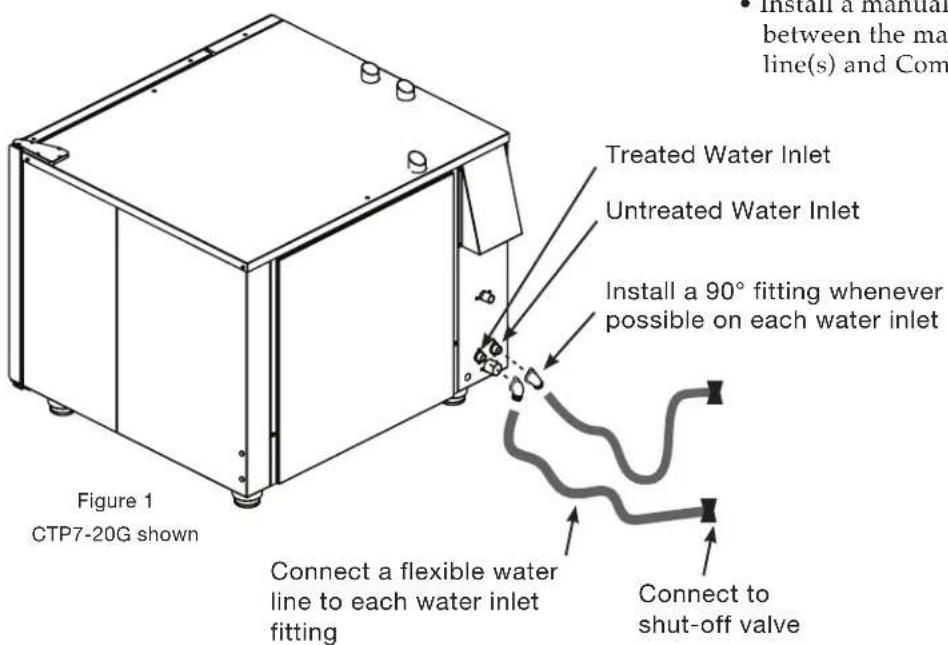
text_image
• Install a manual between the ma line(s) and Com Treated Water Inlet Untreated Water Inlet Install a 90° fitting whenever possible on each water inlet Connect a flexible water line to each water inlet fitting Connect to shut-off valve Figure 1 CTP7-20G shownNOTICE:
To prevent SERIOUS INJURY or PROPERTY DAMAGE:
Two water supplies are required for proper operation of the oven. Either both water supplies should be treated water or one may be treated and the other untreated. NEVER use two untreated water supplies.
Supply lines should be fl exible to allow oven to be moved when service or cleaning is needed.
To prevent water supply lines from bursting, incoming water supply should be turned OFF when not in use.
- Flush the water line at the installation site.
- Backflow Prevention — The equipment must be installed with a check-valve or other anti-backflow/anti-siphon device on all inlet water lines in accordance with and as required by national, state, and local health, sanitation and plumbing codes.
- PIPE SEALING TAPE (TEFLON®) MUST BE USED AT ALL CONNECTION POINTS. The use of a pipe sealing compound is not recommended.
• Install a manual water shut-off valve between the main cold water supply line(s) and Combi supply lines.

natural_image
Simple black silhouette of a person falling backward on a horizontal line (no text or symbols)INSTALLATION
WATER DRAINAGE - FOR SINGLE OVEN
A union is required. Install a 1-1/2-inch (40mm) diameter connection, drain line and clamp into place. The drain line must always be a positive gradient away from the Combitherm oven. An end of drain run air gap may be required by local code. Vertical air vent required.
NOTICE: In the U.S.A., this equipment is to be installed to comply with the Basic Plumbing Code of the Building Officials and Code Administrators International, Inc. [BOCA], and the Food Service Sanitation Manual of the Food & Drug Administration [FDA].

WARNING:
To prevent SERIOUS INJURY or PROPERTY DAMAGE from slippery floor conditions, check drain is connected properly and not blocked.
One suggested method of drain installation.
Drain materials must withstand temperatures up to 200°F (93°C).
Installation kits have a maximum run length of 4-1/2' (1372mm)
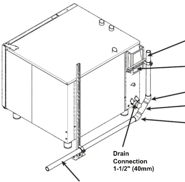
text_image
Drain Connection 1-1/2" (40mm)If a drain run exceeds 6' (1829mm) to the floor sink, an air gap is strongly recommended.
Use only glue designed for CPVC.
Drain vent pipe must be above oven exhaust vent opening!
Oven exhaust vent opening
45 Degree Elbow
1-1/2" (40mm) diameter CPVC Tee Fitting Drain Connection
45 Degree Elbow
1-1/2" (40mm) diameter pipe To Drain - Floor Sink with Positive Descending Slope
INSTALLATION
WATER DRAINAGE - FOR STACKED OVEN
A union is required. Install a 1-1/2-inch (41mm) diameter connection, drain line and clamp into place. The drain line must always be a positive gradient away from the Combitherm oven. An end of drain run air gap may be required by local code. Vertical air vent required.
NOTICE: In the U.S.A., this equipment is to be installed to comply with the Basic Plumbing Code of the Building Officials and Code Administrators International, Inc. [BOCA], and the Food Service Sanitation Manual of the Food & Drug Administration [FDA].

WARNING:
To prevent SERIOUS INJURY or PROPERTY DAMAGE from slippery floor conditions, check drain is connected properly and not blocked.
Installation kits have a maximum run length of 4-1/2' (1372mm).

text_image
Drain Connection 1-1/2" (40mm) diameterOne suggested method of drain installation.
Drain materials must withstand temperatures up to 200°F (93°C).
If a drain run exceeds 6' (1829mm) to the floor sink, an air gap is strongly recommended.
When stacking ovens, run independent drains.
Use only glue designed for CPVC.
Drain vent pipes must be above oven exhaust vent opening!
Exhaust vent opening
1-1/2" (40mm) CPVC Tee Fitting Drain Connection
45 Degree Elbow
1-1/2" (40mm) diameter CPVC Tee Fitting Drain Connection
45 Degree Elbow
1-1/2" (40mm) diameter pipe To Drain - Floor Sink with Positive Descending Slope
MOBILE EQUIPMENT RESTRAINT
For Gas Models:
The gas Combitherm must use a connector that complies with The Standard for Connectors for Movable Gas Appliances, ANSI Z21.69 CSA 6.16 and addenda Z21.69a-1989. A quick disconnect device must be installed to comply with The Standard for Quick Disconnect Devices for Use with Gas Fuel, ANSI Z21 CSA 6.9. and European Standard EN203.
Adequate means must be provided to limit the movement of this appliance. Limitation of movement must be made without depending on the connector, the quick disconnect device, nor the associated piping designed to limit appliance movement. If it becomes necessary to disconnect the restraint, it must be reconnected immediately following the return of the appliance to its original position.
- Install a manual gas shut-off valve along with an approved disconnect device.
- Install an A.G.A. certified, heavy-duty connector that complies with ANSI Z 21.69 or CAN 1-6.10m88 along with a quick-disconnect device in compliance with ANSI Z21.41 or CAN 1-6.9m70. Connectors must be installed with a cable restraint to prevent excessive tension from being placed on the connector.
FIRE HAZARD

To prevent SERIOUS INJURY or DEATH, your appliance must be secured to building structure to prevent unintended movement.
For Electric Models:

This section is provided for the assistance of qualified and trained service technicians only and is not intended for use by untrained or unauthorized service personnel. Failure to observe this precaution may void the warranty.
Any appliance that is not furnished with a power supply cord but includes a set of casters must be installed with a tether. Adequate means must be provided to limit the movement of this appliance without depending on or transmitting stress to the electrical conduit. The following requirements apply:
- Casters must be a maximum height of 6" (152mm).
- Two of the casters must be the locking type.
- Such mobile appliances or appliances on mobile stands must be installed with the use of a fl exible connector secured to the building structure.
WARNING

ELECTRIC SHOCK HAZARD.
To prevent SERIOUS INJURY or DEATH, your appliance must be secured to building structure to prevent unintended movement.
A mounting connector for a restraining device is located on the lower back fl ange of the appliance chassis or on an oven stand, approximately 18" (457mm) from the floor. A fl exible connector is not supplied by nor is it available from the factory.
NOTICE: The mobile base used on stacked ovens is not adjustable. The equipment must be placed on a stable, non-combustible level horizontal surface.
INSTALLATION
CombiHood PLUS™ Ventless Hood Option

natural_image
Simple line drawing of a rectangular box with a small protrusion on top (no text or symbols)The CombiHood PLUS option is factory installed directly on the top of the Alto-Shaam Combitherm CTP or CTC series oven.
- Using EPA method 202 testing, grease laden vapors emitted by the Combi Ventless hood are 0.58mg / m3 - far less than U.L.'s established standard of 5mg / m3 .
- Alto-Shaam's factory installed Ventless Hood is placed directly on the top of a Combitherm oven.
- A high-power fan captures all steam and fumes from the oven cavity into the hood intake and out the back surface exhaust vent, trapping grease as the air moves through the filter system.
- As fumes and vapors are circulated through the hood, condensed steam drains from a drain at the rear of the hood.
- An activated charcoal filter cleans the air before venting it out the top of the hood.
- CombiHood PLUS™ performance is “smart”; engaging the fan during the last minute of the cook mode which provides quiet operation and consumes less power.

text_image
FRONT OF HOOD ALIGNS WITH FRONT OF COMBI DOORCondensate Drain
A ventless hood condensate drain line to the floor drain must be installed. The 1/2" barbed connection is found at the back of the hood.
The drain line must always be a positive gradient away from the Combitherm oven.
Test the drain for proper drainage and signs of leaking on a monthly basis.
INSTALLATION
CombiHood PLUS™ Ventless Hood Option

text_image
Quarter Turn Release (access to filters) 1 2 Quarter Turn Release (access to filters)1GreaseFilter
(5017362):
Cleaning frequency should be based on oven usage with a maximum of two weeks between cleaning if the oven is used for non-grease laden products or steam applications only. Grease laden products require cleaning frequency of at least once a week.
Remove the grease filter by pulling it straight out of the housing. Place the filter in the dishwasher or wash separately by placing in hot, soapy water until all grease and particles have been removed. Rinse thoroughly. Allow the filter to air dry before reinstalling.
To replace the grease filter, the air flow arrow on the filter casing should be pointing toward the hood fan.
2CharcoalFilter
(Class I - FI-36620):
The charcoal filter should be inspected once a month for contaminants. Replacement must be made at a minimum of three month intervals — more often if heavy contaminants are visible or if the filter no longer controls odors.
To remove the filter, pull and slide out while holding the bottom housing. When replacing the filter, make certain the air flow arrow(s) point toward the hood fan, and that the filter is replaced in the three-sided metal frame provided with the hood.
NOTICE: A pressure switch is used to detect when the airflow through the charcoal filter is reduced by 25% - indicating a possible blockage. This will generate an E101 error message on the oven control display. The filters will need to cleaned or replaced.
If the filters are not seated properly, an error code E102 will appear on the oven control display at the end of a cooking cycle.
INSTALLATION
GREASE COLLECTION INSTALLATION (IF EQUIPPED WITH THIS OPTION)
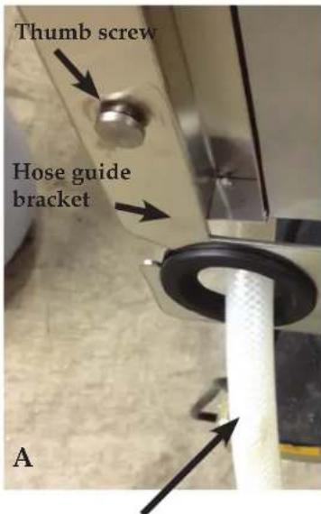
text_image
Thumb screw Hose guide bracket AGrease Collection Hose
Hose hanger bracket with fi lm

text_image
LASER FILM J-Novace
text_image
WS-22295 WS-22301 SC-22779 DHose hanger bracket
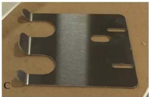
natural_image
Metallic U-shaped metal plate with two slots, placed on a wooden surface (no text or symbols visible)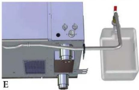
natural_image
3D mechanical assembly diagram showing a precision optical or laser unit with control panel and wiring (no text or symbols visible)- Grease Collection Hose Assembly is attached to the oven in the back.
- The hose guide bracket can be attached on either the left side or the right side toward the back. Placement on the left side is recommended whenever possible. Thumb screws are in position for this purpose. Remove thumb screws, position hose guide bracket and secure screws (PHOTO A). Thread grease hose through the guide.
- The hose hanger bracket can be attached on either the left side or the right side toward the front of the oven. Placement on the left side is recommended whenever possible. Remove the plastic protective film from the bracket (PHOTO B,C). Pan head screws are in position beneath the oven for this purpose. For stacked configurations, always place the hanger bracket on bottom of the top oven. Remove pan head screws and washers (PHOTO D), position hose hanger bracket on either side of the oven and secure screws and washers (PHOTO E,F). The hanger bracket is used to secure the grease collection hose while changing grease collection containers.
- Place Grease Collection Containers inside the tray of the Mobile Grease Collection Cart. Roll into place next to the oven and apply the caster brake.
- Loosen vent cap on container. Pull out the Grease Collection Hose Assembly from the back of the unit. Remove collection container fill cap (PHOTO G).
- Screw Grease Collection Hose Assembly on to collection container until snug.
- Turn ball valve handle to the ON position.
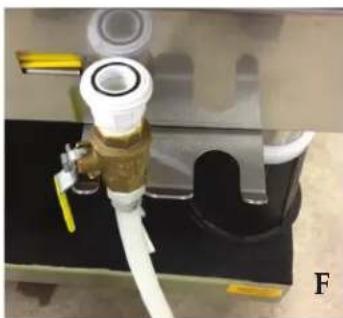
natural_image
Close-up of a mechanical assembly with a white pipe fitting and blue fittings, no visible text or symbols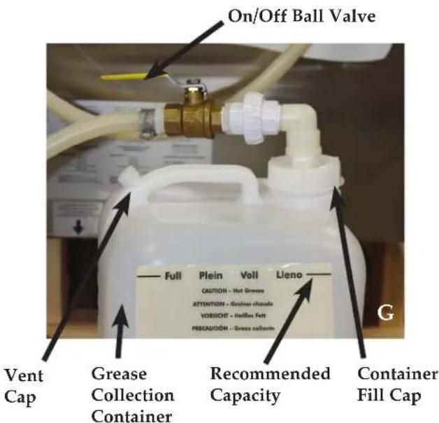
text_image
On/Off Ball Valve Full Plein Voll Lleno CAUTION - Hot Greenes ATTENTION - Green shades VORSICH - Halles Ferr PENGAVIDÓN - Gross solvents Vent Cap Grease Collection Container Recommended Capacity Container Fill CapINSTALLATION
Liquid Cleaner Hook-Up (If Equipped with this Option)
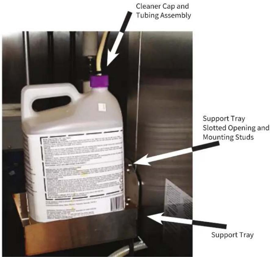
text_image
Cleaner Cap and Tubing Assembly Support Tray Slotted Opening and Mounting Studs Support Tray- Removable, cleaner support tray can be mounted on the left or right exterior wall of the oven. Slide slotted openings on the tray over the mounting studs.
- Support tray holds a 2-1/2-gallon (9,5 liter) bottle and measures 10-1/2" x 7-3/4" (267mm x 194mm).
- Place liquid oven cleaner bottle inside tray.
Wearing protective rubber gloves and eye wear, remove cap from liquid oven cleaner bottle. Pull out the Cleaner Cap and Tubing Assembly from the back of the unit screw on to liquid oven cleaner bottle. - Position cap to ensure the hose is not kinked after tightening.
- Combitherm liquid oven cleaner jugs are quickly and easily replaced.
• Combitherm liquid oven cleaner is automatically pumped through the system, saving labor and providing greater employee safety by eliminating the need to handle caustic cleaning liquids each day.
WARNING
ALWAYS wear protective eye wear and rubber gloves when using liquid oven cleaner to prevent eye, skin, and respiratory tract irritation.
Keep out of reach of children.
See Safety Data Sheet for additional information.
WARNING

To prevent SERIOUS INJURY or DEATH, NEVER operate this appliance in a cleaning mode without the liquid cleaner connected, with a kink in the cleaning hose line, or with an empty liquid cleaner container. Failure to do so may result in poor oven cleaning, grease and/or carbon accumulating inside the oven cavity and increased risk of fire.
WARNING
To prevent SERIOUS PERSONAL INJURY, DEATH, or PROPERTY DAMAGE:
The appliance must be cleaned thoroughly to avoid deposits of grease and or food residues inside the appliance that may catch fire. If fat deposits and/or food waste inside the appliance ignite, shut down the appliance immediately and keep the appliance door closed to extinguish the fire. If further extinguishing is required, disconnect the appliance from the main power and use a fire extinguisher (do not use water to extinguish a grease fire!). Failure to clean the appliance properly invalidates the warranty and relieves Alto-Shaam of all liability.
CT PROFORMANCE™ START-UP PROCEDURES
Turn on water supply.
Turn on gas supply valve (if applicable).
Turn on main electrical power to appliance.
Press Power ON icon on the appliance control panel.

The oven will automatically fill the steam generator equipped models with water that will heat to a stand-by mode temperature of 188^ F ( 77^ C).
NOTE: To power off the appliance, press and hold the power icon for 5 seconds to initiate power shut down sequence to the oven. Oven will not shut down during a cooking cycle. From time to time, the control may become unresponsive. ONLY when this happens, firmly press and hold the power key for 10 seconds to power down the oven.
If, for any reason, the oven is turned off or loses power during this start-up process, the operator will be prompted to calibrate the Touch screen when the oven is next powered up.
Return to Home Screen - Press the red arrow if the PROtouch™ screen does not need to be calibrated.
Begin Calibration Process - Press the green check mark if the Touch screen does need to be calibrated. The screen will switch to a grey background. See illustration at right. A crosshairs icon will appear. The operator should touch the center intersection using a stylus for an accurate calibration. This prompt and required action will be repeated several times in different areas of the Touch screen. When complete, the operator will be returned to the Home screen.
NOTICE: Accumulations on the main burners can result in fi ring out of normal sequence. This delayed ignition creates an alarmingly loud sound. If your appliance makes an especially loud noise when starting up, shut down your appliance and call a qualifi ed and trained service technician.
In the event of a power failure, the oven will not operate.

text_image
ALTO-SHAAM® PROtouch™When the oven is powered on, the PROtouch screen illuminates. “Loading” indicates that the soft ware is booting up. The screen will also indicate what level of progress has been made as the soft ware becomes fully operational.

natural_image
Blank gray rectangle with a small plus sign in the bottom-left corner (no text or symbols beyond the plus)
natural_image
Blank gray rectangular image with a small plus sign in the top-right corner (no text or symbols beyond the plus)DANGER

Before starting the appliance, make certain you do not detect the odor of gas.
If you smell gas:
- Shut off the gas supply immediately.
- Do not attempt to light any appliance.
- Do not touch any electrical elements.
- Extinguish any open flame.
- Evacuate the area.
- Use a telephone outside the property and immediately contact your gas supplier.
- If unable to contact your as supplier, contact the fire department.
CT PROFORMANCE™ START-UP PROCEDURES
CONTINUED
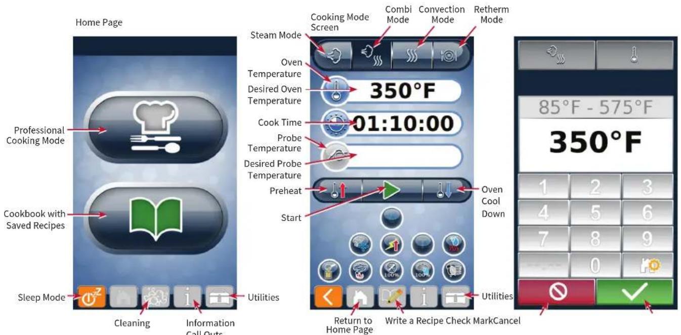
text_image
Home Page Professional Cooking Mode Cookbook with Saved Recipes Sleep Mode Cleaning Information Call Outs Utilities Steam Mode Cooking Mode Screen Combi Mode Convection Mode Retherm Mode Oven Temperature 350°F Desired Oven Temperature Cook Time 01:10:00 Probe Temperature Desired Probe Temperature Preheat Start Return to Home Page Write a Recipe Check MarkCancel 85°F - 575°F 350°F 1 2 3 4 5 6 7 8 9 0 0 0 0 0 0 0 0 0 0Preheating the Appliance
- Press the Power button.
- Touch the Professional Cooking Mode icon.
- Touch the desired Cook Mode icon.


- Touch the Preheat icon.
- Enter the temperature on the touch pad, then touch the Check Mark icon.

Appliance beeps when it is preheated.

CT CLASSIC™ START-UP PROCEDURES
- Turn on exhaust hood.
- Turn on water supply.
- Turn on gas supply valve (if applicable).
- Turn on main electrical power to appliance.
- Push power ON icon on the appliance's control panel.

The oven will automatically fill the steam generator equipped models with water that will heat to a stand-by mode temperature of 188^ F ( 77^ C).
Note: To power off the appliance, press and hold the power icon for 5 seconds to initiate power shut down sequence to the oven. Oven will not shut down during a cooking cycle. From time to time, the control may become unresponsive.
ONLY when this happens, firmly push and hold the power button for 10 seconds to power down the oven.
Preheat the oven
Alto-Shaam recommends preheating the Combitherm® before cooking.
- Choose a Mode.

Steam

Combi

Convection
- PushTemperature button; adjust temperature with arrows.


- PushCook Time button; adjust time with arrows.


- Push Start/Stop.

- Preheat oven before loading food.
DANGER

Before starting the appliance, make certain you do not detect the odor of gas.
If you smell gas:
- Shut off the gas supply immediately.
- Do not attempt to light any appliance.
- Do not touch any electrical elements.
- Extinguish any open flame.
- Evacuate the area.
- Use a telephone outside the property and immediately contact your gas supplier.
- If unable to contact your as supplier, contact the fire department.
NOTICE: In the event of a power failure, the oven will not operate.
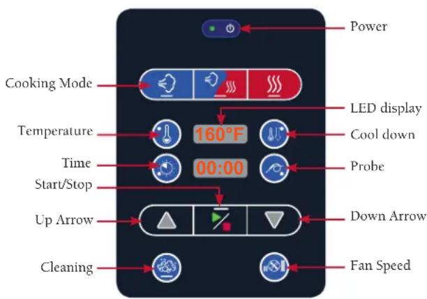
text_image
Power Cooking Mode LED display Temperature 160°F Cool down Time 00:00 Probe Start/Stop Up Arrow Down Arrow Cleaning Fan SpeedFactory Authorized Combitherm® Installation Program
POST-INSTALLATION CHECKLIST
Location Information
Location Name: ____
Location Street Address: ____
Location City:
Location State: ____ Zip: ____
Site Contact Name: ____
Site Contact Phone No.:
State: ____ Zip: ____
Technician Name: ____
Technician Phone No.:
Contact Email:
| Model number(s) of combi's installed | ||||
| Serial number of combi's installed | ||||
Clearance
| Appliance clearance Right side | PASS FAIL | |||||
| Left side | PASS FAIL | |||||
| Rear | PASS FAIL | |||||
| Top | PASS FAIL | |||||
| Is the appliance accessible for service? YES NO | ||||||
| If NO, comment on the issue: | ||||||
| Other comments: | ||||||
Water Supply
| Have all Y1/Y3 water lines been connected to water supply (treated/filtered line, if provided)? | PASS FAIL | |||||||
| Have all Y2/Y4 water lines been connected to water supply? PASS FAIL | ||||||||
| Do water supply line(s) have shut-off (s) exclusively for each appliance? | PASS FAIL | |||||||
| Is the dynamic water pressure from the 3/4" cold water supply line a minimum of 30 psi for each appliance? | PASS FAIL UNKNOWN | |||||||
| Is the static water pressure from the 3/4" cold water supply line less than 90 psi for each appliance? | PASS FAIL UNKNOWN | |||||||
| Is water treatment (RO blend system, filter, etc.) being used? YES NO | TYPE | |||||||
| If YES - Note the system here: BRA | ND NAME | MODEL | ||||||
| Are all exterior water connections tight? | YES NO | |||||||
| Are all interior water connections tight prior to operation? | YES NO | |||||||
| Are there any exterior water leaks after operation? | YES NO | |||||||
| Are there any interior water leaks after operation? | YES NO | |||||||
| Comments: | ||||||||
Factory Authorized Combitherm® Installation Program POST-INSTALLATION CHECKLIST
| Electrical | ||||||||
| What is the rated voltage and phase of the appliance(s) installed? | VOLTAGE PHASE | |||||||
| Is the wire size for the main incoming power to the appliance(s) in accordance with the minimum size listed in the specification sheet for this specific appliance? | PASS FAIL | |||||||
| What is the measured voltage at site? L1-N L2-N L3-N L1-L2 | ||||||||
| L2-3 L | 1-L3 PASS FAIL | |||||||
| What is the current draw of the appliance(s) to be supplied? | AMP RATING | |||||||
| What is the on-site breaker size supplying power to the appliance(s)? | SIZE PASS FAIL | |||||||
| Is there a disconnect or junction box within 3' (914mm) of where the appliance(s) will be installed? | PASS FAIL | |||||||
| Comments: | ||||||||
| Gas | ||||||||
| Does the gas supply match the information listed on the nameplate of the appliance(s)? | PASS FAIL | |||||||
| What is the rated gas supply type? | NAT PRO | |||||||
| What is the actual gas supply type? | NAT PRO | |||||||
| Is the gas supply piping, water hose lines, electrical support cord and/or receptacle routed away from the path of any hot combustion pipes or fumes? | PASS FAIL | |||||||
| Comments: | ||||||||
| Drain | ||||||||
| What type of material was used for the drain? | ||||||||
| Does the vertical drain vent extend above the appliance exhaust opening at the rear of the appliance? | PASS FAIL | |||||||
| Is there a vertical vent within 12" (305mm) of the appliance drain? | PASS FAIL | |||||||
| Is there an air gap installed at the end of the drain run? | PASS FAIL SIZE | |||||||
| Is the drain piped with a positive descending slope? | PASS FAIL | |||||||
| If the appliance has a ventless hood (appliance model name ending in “EVH”), has the ventless hood drain been plumbed along with the appliance main drain. | PASS FAIL | |||||||
| Comments: | ||||||||
| Other Site Information | ||||||||
| Is there a proper ventilation hood installed above the location of the appliance(s)? | PASS FAIL | |||||||
| Is the appliance level according to leveling instructions in the installation manual? | PASS FAIL | |||||||
| Comments: | ||||||||
Factory Authorized Combitherm® Installation Program
FUNCTION TEST CHECKLIST
| Wire Connections | |||||
| Behind the left side panel, check and tighten all electrical connections, and tighten all electrical screws. | |||||
| Behind the left side panel, check and tighten all electrical screws. | |||||
| Behind the control panel, check and tighten all connections on the control board. | |||||
| Behind the control panel, check and tighten all connections on the options board. | |||||
| Behind the control panel, check and tighten all connections on the interface board. | |||||
| Check that the SD card is fully inserted into the interface board. | |||||
| Comments: | |||||
| Gas Appliances | |||||
| With the burner on, check the following: | |||||
| Static gas pressure at gas valve must be less than 14" W.C. | |||||
| Dynamic gas pressure at gas valve must be greater than 5.5" W.C. for NG; 9" W.C. for propane | |||||
| CO2 flue gas analysis | |||||
| Were burner adjustments required? YES NO | |||||
| If YES, Record CO2 values | |||||
| CTP/CTC Appliance Function Test | |||||
| Cycle Y1 - Operation fill/Steam injection YES NO | |||||
| Dynamic water pressure with Y1 MEASURE | |||||
| Cycle Y2 - Operation condensate cooling valve YES NO | |||||
| Dynamic water pressure with Y2 MEASURE | |||||
| Cycle Y3 - Operation rinse solenoid valve YES NO | |||||
| Dynamic water pressure with Y3 MEASURE | |||||
| Cycle appliance in steam mode at 212° Fahrenheit (100° Celsius) for 10 minutes. Did the appliance perform correctly? | PASS FAIL | ||||
| Record amperage at all phases: L1 L2 | |||||
| L3 | |||||
| During the cycle, check CTP motor rotation: 3 minutes clockwise - break - 3 minutes counter-clockwise | PASS FAIL | ||||
| Cycle appliance in convection mode at 350° Fahrenheit (175° Celsius) for 10 minutes. Did it perform correctly? | PASS FAIL | ||||
| Record amperage at all phases: L1 L2 | |||||
| L3 | |||||
| Cycle appliance in combination mode at 400° Fahrenheit (205° Celsius) for 10 minutes. Did it perform correctly? | PASS FAIL | ||||
| Record amperage at all phases: L1 L2 | |||||
| L3 | |||||
| Check motor rotation for CTC models. Note: Arrows on the motor housing indicate proper rotation. | PASS FAIL | ||||
Factory Authorized Combitherm® Installation Program
FUNCTION TEST CHECKLIST
| Installation Complete | ||||
| Cleanup job site | ||||
| Wipe down and clean exterior of combi appliance | ||||
| Picture of screen displaying current soft ware versions | ||||
| Picture(s) of complete drain run | ||||
| Picture of water connections at combi appliance | ||||
| Picture of gas line and connections at combi appliance | ||||
| Picture of appliance in place with surrounding equipment | ||||
| Are water supply lines 3/4" inside diameter? | YES NO | |||
| Size of treated water line: | ||||
| Size of untreated water line: | ||||
More frequent preventative maintenance inspection/service is required when cooking large quantities of fatty foods. The acids and related compounds found in fat, particularly chicken fat, accumulate over time and can damage appliance components. Failure to regularly inspect and maintain the appliance may result in void of warranty, property damage, or personal injury.
| ALTO-SHAAM - UNIT INFORMATION | |
| Business Name: | -------- |
| Model Number: | -------- |
| Serial Number: | -------- |
| Daily Inspection - Start Date: | -------- |
DAILY INSPECTION CHECKLIST
| INSPECT & CLEAN: | Monday | Tuesday | Wednesday | Thursday | Friday | Saturday | Sunday |
| Product Probe (Thermometer) | |||||||
| Door Gasket (Inner Door Seal) | |||||||
| Inncr Door Glass | |||||||
| Front Drip Tray | |||||||
| Touchscreen & Overlay(Inspect for cracks, peeling, moisture, etc) | |||||||
| Execute Automatic Wash Cycle(With Approved Cleaning Chemical ONLY) | |||||||
| EMPLOYEE INITIALS |
COMPONENT FAILURE & REPLACEMENT
| List details of the failure(s) beside the day they occurred. (Leave blank if components are working properly) | |
| Monday | |
| Tuesday | |
| Wednesday | |
| Thursday | |
| Friday | |
| Saturday | |
| Sunday | |
More frequent preventative maintenance inspection/service is required when cooking large quantities of fatty foods. The acids and related compounds found in fat, particularly chicken fat, accumulate over time and can damage appliance components. Failure to regularly inspect and maintain the appliance may result in void of warranty, property damage, or personal injury.
| ALTO-SHAAM - UNIT INFORMATION | |
| Business Name: | -------- |
| Model Number: | -------- |
| Serial Number: | -------- |
| Weekly Inspection - Date: | -------- |
WEEKLY INSPECTION CHECKLIST
| Inspect - Oven Cavity Lamp | ||
| Inspect - Oven Cavity for signs of Grease/Carbon Buildup | ||
| Inspect - Behind the Fan Panel inside the Oven Cavity for signs of Grease/Carbon Buildup | ||
| Inspect - Behind the Fan Panel inside the Oven Cavity for signs of Scale Buildup | ||
 | Inspect - The Heat Exchanger for any signs of major deformation(If Yes, IMMEDIATELY remove from service and take corrective action steps) | |
 | Inspect - The Heat Exchanger for any loose/disconnected pipes or flanges(If Yes, IMMEDIATELY remove from service and take corrective action steps) | |
 | Inspect - Convection Elements for signs of cracking, deformation, or damage | |
 | Clean Ventless Hood grease filters | |
| EMPLOYEE INITIALS | ||
| COMPONENT FAILURE & REPLACEMENT | |
| List details of the weekly failure(s) beside the week they occurred. (Leave blank if items are working properly) | |
| Week 1 | |
| Week 2 | |
| Week 3 | |
| Week 4 | |
More frequent preventative maintenance inspection/service is required when cooking large quantities of fatty foods. The acids and related compounds found in fat, particularly chicken fat, accumulate over time and can damage appliance components. Failure to regularly inspect and maintain the appliance may result in void of warranty, property damage, or personal injury.
| ALTO-SHAAM - UNIT INFORMATION | |
| Business Name: | -------- |
| Model Number: | -------- |
| Serial Number: | -------- |
| Monthly Inspection - Date: | -------- |
MONTHLY INSPECTION CHECKLIST
| Inspect/Test - Proper Draining of the Oven Cavity | |
| Inspect - All Drain Lines for Leaks or Clogs | |
| ELEC. BOILERUNITS ONLYDescale the Steam Generator | |
| Inspect - Oven Cavity for any signs of Scale Buildup | |
| Descale the Oven Interior | |
| Inspect Ventless Hood paper filter (replace as needed) | |
| Test Ventless Hood drain for proper drainage and signs of leaking | |
| EMPLOYEE INITIALS |
COMPONENT FAILURE & REPLACEMENT
| Summarize any component failure(s) that may have occurred during this month. (Leave blank if items are working properly) |
| Summary of the month's component failure at replacement. |
More frequent preventative maintenance inspection/service is required when cooking large quantities of fatty foods. The acids and related compounds found in fat, particularly chicken fat, accumulate over time and can damage appliance components. Failure to regularly inspect and maintain the appliance may result in void of warranty, property damage, or personal injury.
| ALTO-SHAAM - UNIT INFORMATION | |
| Business Name: | -------- |
| Model Number: | -------- |
| Serial Number: | -------- |
| 12 Month Inspection - Date: | -------- |
| TWELVE-MONTH INSPECTION CHECKLIST | ||
| Replace - Steam Bypass Hose | ||
| Inspect - Cleaning Pump Hose | ||
| Inspect/Test - Proper Draining of the Oven Cavity | ||
| Inspect -AllDrain Lines for Leaks or Clogs | ||
| Inspect -AllSolenoid Hoses (Both Ends) | ||
| Inspect - Upper Browning Valve Hose | ||
| Inspect - Low Pressure Relief Valve & Hose | ||
| ELEC. UNITS ONLYInspect - Convection Element Seal (from the electrical compartment) | ||
| GAS UNITS ONLYInspect - Gas Heat Exchanger Seal (from the electrical compartment) | ||
| Inspect - N6 Oven Temperature Probe Seal | ||
| ELEC. BOILER UNITS ONLYDescale the Steam Generator | ||
| ELEC. BOILER UNITS ONLYRemove & Inspect - Steam Generator Elements | ||
| Inspect - Hand Shower Hose | ||
| Inspect - Hand Shower Handle | ||
| Inspect - Product Probe | ||
| Inspect - Water Injection Tube | ||
| Inspect - Oven Cavity for any signs of Scale Buildup | ||
| Inspect - Oven Cavity Lamp | ||
| Inspect - Oven Cavity for signs of Grease/Carbon Buildup | ||
| Inspect - Behind the Fan Panel inside the Oven Cavity for signs of Grease/Carbon Buildup | ||
| Inspect - Behind the Fan Panel inside the Oven Cavity for signs of Scale Buildup | ||
 | Inspect - The Heat Exchanger for any signs of major deformation(If Yes, IMMEDIATELY remove from service and take corrective action steps) | |
 | Inspect - The Heat Exchanger for any loose/disconnected pipes or flanges(If Yes, IMMEDIATELY remove from service and take corrective action steps) | |
 | Inspect & Ensure - Exhaust Pipes are Exiting the Oven Cavity | |
 | Inspect - Heat Exchanger Flange Gasket (Replace as Needed) | |
 | Inspect & Tighten - Heat Exchanger Flange Bolts | |
 | Inspect & Tighten - Heat Exchanger Burner Flange Hardware & Gasket(Replace as Needed) | |
 | Inspect & Tighten - Heat Exchanger Igniter Flange Hardware & Gasket(Replace as Needed) | |
 | Inspect - Heat Exchanger Exhaust Pipes(Ensure they are exiting out past the oven cavity ceiling flange) ESG models only | |
 | Inspect - Oven Cavity Ceiling Flange & Flange Gasket - ESG models only | |
 | Tighten - Burner Flange Bolts | |
 | Tighten - Igniter Flange Bolts | |
| Inspect - Heat Exchanger Weep Holes to ensure they are free of obstructions(If the hole is obstructed, IMMEDIATELY remove oven from service and replace the Heat Exchanger) Not applicable to CTP/CTC models | ||
| ELEC. UNITS ONLY | Inspect - Convection Elements for signs of cracking, deformation, or damage | |
| Replace - Oven Lamp Cover(s) & Gasket(s) | ||
| Descale the Oven Interior | ||
| Inspect - Door Gasket (Replace as Needed) | ||
| Wipe Down the Inner Door Glass | ||
| Inspect - Front Drip Tray (Clean as Needed) | ||
| Inspect - Front Drip Tray Hose | ||
| Inspect - Control Overlay | ||
| Inspect & Tighten - All Electrical Connections | ||
| Inspect & Test - All cooling fans for proper operation | ||
| Inspect & Tighten - Door Hinges | ||
| Inspect & Tighten - Door Handle | ||
| Review - Error Code History | ||
| Note the Software Version (Update if Not Current) | ||
| Record - Water Pressure (Static & Dynamic) | ||
| Record - Line Voltage Across All Lines | ||
| Record - Line Voltage to Ground on Each Line | ||
| Record - Amperage Across All Three Legs (WHEN HEATING) | ||
| Function Test All Components (List Components) | ||
COMPONENT FAILURE & REPLACEMENT
Note any component failure that was discovered during this twelve month inspection. (Leave blank if items are working properly)
Summary of the twelve month component failure or replacement:
Customer Signature
Technician Signature
TROUBLESHOOTING
Error Codes
ALWAYS check the circuit breaker is turned "ON" and your unit is receiving power BEFORE calling your Authorized Alto-Shaam Service Agent.
NOTICE
This section is provided for the assistance of qualified and trained service technicians only and is not intended for use by untrained or unauthorized service personnel. Do not attempt to repair or service the oven beyond this point. Contact Alto-Shaam for the nearest authorized service agent. Repairs made by any other service agents without prior authorization by Alto-Shaam will void the warranty.
When the oven malfunctions, an error code will appear in the display.

Press the Start icon to acknowledge the error.
When the oven error notification has been acknowledged, the Combitherm will attempt to return to normal operation.
| Error Code | Error Call Out in Display Description of Error Possible Cause(s) | ||
| E01 Low | Water Boiler Upper water level probe B1 is not satisfied within 5 minutes, after water solenoid valve Y1 is activated. | — Water supply is shut off .— Low water pressure.— Boiler drain cap is missing.— Boiler drain pump is defective.— Drain pump elbow leaking.— Water level probe has calcium build up.— Double water solenoid valve is defective (Y1).— Relay board, high voltage is defective. | |
| E02 Control Temperature High Low voltage relay board temperature higher than 176°F (80°C). | — Check wiring to all components listed below.— Cooling fan on relay board assembly is defective.— Cooling fan on display board assembly is defective.— Main cooling fan is defective.— Cooling fan on motor drive is defective. | ||
| E03 Fan | Motor Error Fan motor does not spin after 60 seconds, detected by the Hall Sensor.Error 03 does not appear if error E53 is detected first. | — Check wiring to all components listed below.— If LED on motor control flashes, see error codes for motor control.— Motor or fan wheel locked.— Hall sensor does not detect motor rotation.— Motor Thermo Temperature protection.— Fan wheel damaged. | |
| E04 Lower Fan Motor Error Lower Fan motor does not spin after 60 seconds, detected by the Hall Sensor.Error 04 does not appear if error E54 is detected first. | — Check wiring to all components mentioned below.— If LED on motor control flashes, see error codes for motor control.— Motor or fan wheel locked.— Hall sensor does not detect motor rotation.— Motor Thermo Temperature protection.— Fan wheel damaged. | ||
| E05 VFD | Comm Failure When VFD does not respond to a query on the CAN interface. | — Loss of power to VFD.— VFD malfunction.— CAN cable disconnected.— CAN address not correct on VFD. | |
CONTINUED ON NEXT PAGE
TROUBLESHOOTING
Error Codes
| Error Code | Error Call Out in Display Description of Error Possible Cause(s) | ||
| E06 Lower VFD Comm Failure When VFD does not respond to a query on the CAN interface. | — Loss of power to VFD.— VFD malfunction.— CAN cable disconnected.— CAN address not correct on VFD. | ||
| E07 Error Received from VFD When VFD is flashing the green light | — Refer to VFD error code list and match to number of blinks on the green LED of VFD. | ||
| E08 Error Received from Lower VFD | When VFD is flashing the green light | — Refer to VFD error code list and match to number of blinks on the green LED of VFD. | |
| E11 Convection Temperature High In Combination program, cavity temperature N6 is measuring in excess of 572°F (300°C) for a minimum of 25 secondsIn Convection program, cavity temperature N6 is measuring in excess of 572°F (300°C) for a minimum of 25 seconds | — Check wiring to all components mentioned below.— Steam element contactor locked/on.— N6 oven cavity temperature probe is defective.— N6 oven cavity temperature probe wires connected backwards— Relay board, high voltage, defective. | ||
| E13 Boiler Temperature High Boiler temperature is more than 248°F (120°C) for more than 25 seconds, detected by B4 Probe | — Calcium build up in boiler— Check wiring to all components mentioned below.— Steam element contactor locked/on.— B4 boiler temperature probe is defective.— B4 probe wires connected backwards— Water level probe has calcium build up. | ||
| E15 Condensor Temperature High Condensor water temperature is more than 212°F (100°C) for more than 180 seconds, detected by B3 probe | — Water supply is shut off.— Check wiring to all components mentioned below.— B3 condensor temperature probe is defective.— B3 condensor probe wires connected backwards— Single water solenoid valve defective (Y2).— Relay board, high voltage, defective. | ||
| E20 B11 Core Temperature ProbeSingle Point Fault | Single point core temperature probe defective or disconnected | — Clean probe receptacle pins with sand paper.— B11 Single Point Core Temperature probe with quick connect defective.— B11 Single Point Core Temperature probe wires with quick connect disconnected.— B11 Single Point Core Temperature probe receptacle defective.— B11 Single Point Core Temperature probe receptacle wires disconnected. | |
| E21 N6 Cavity Probe Fault Cavity temperature probe defective or disconnected | — N6 oven cavity temperature probe defective.— N6 oven cavity temperature probe wires. | ||
| E22 B10 Core Temperature ProbeMulti-point Fault | Multipoint core temperature probe defective or disconnected | — B10 multipoint core temperature probe defective.— B10 multipoint core temperature probe wires disconnected. | |
CONTINUED ON NEXT PAGE
TROUBLESHOOTING
Error Codes
| Error Code | Error Call Out in Display Description of Error Possible Cause(s) | ||
| E23 B4 | Boiler Probe Fault Boiler temperature probe defective or disconnected | — B4 boiler temperature probe defective.— B4 probe wires connected backwards. | |
| E24 B5 | Bypass Probe Fault Bypass steam temperature probe defective or disconnected | — B5 bypass steam temperature probe defective.— B5 bypass steam temperature probe wires connected backwards. | |
| E25 B3 | Condensor Probe Fault Condensor water temperature probe defective or disconnected. | — B3 condensor temperature probe defective.— B3 condensor probe wires connected backwards. | |
| E26 N8 | Boiler Safety Temperature Probe Fault | Boiler heating element protection probe defective or disconnected. | — N8 boiler temperature probe defective.— N8 probe wires connected backwards. |
| E27 | Boiler Element Temperature High | Boiler protection heat element temperature detected by N8 probe is more than 266°F (130°C) for more than 25 seconds, or has reached 275°F (135°C). | — Calcium build up in boiler.— Check wiring to all components mentioned below.— Steam element contactor locked/on.— N8 boiler temperature probe defective.— N8 probe wires connected backwards.— Water level probe has calcium buildup. |
| E34 | Steam Generator Drain Pump Fault | If water level does not drop below lower water level probe after three minutes when steam generator drain pump is activated in cleaning program. | — Calcium build up in steam generator drain pump.— Boiler drain pump defective.— Relay board, high voltage, defective.— Water level probe defective. |
| E36 | Steam Temperature High In Steam program, cavity temperature N6 is measuring in excess of 395°F (200°C) for more than 60 Seconds.In Combination program, cavity temperature N6 is measuring in excess of 520°F (270°C), for more than 60 Seconds.In Retherm program, cavity temperature N6 is measuring in excess of 395°F (200°C), for more than 60 Seconds.In Cleaning program, cavity temperature N6 is measuring in excess of 395°F (200°C), for more than 60 Seconds. | — Water supply is shut off.— Low water pressure.— Water injection pipe, calcium build up.— Water flow valve defect or calcium build up.— Double water solenoid valve defective (Y1).— Relay board, high voltage, defective. | |
| E40 B3 | Fault B3 probe shorted to ground — Defective or miss wired probe. | ||
| E41 B4 | Fault B4 probe shorted to ground — Defective or miss wired probe. | ||
| E42 B5 | Fault B5 probe shorted to ground — Defective or miss wired probe. | ||
| E43 N6 | Fault N6 probe shorted to ground — Defective or miss wired probe. | ||
| E44 N8 | Fault N8 probe shorted to ground — Defective or miss wired probe. | ||
| E45 | B10 Fault | B10 probe shorted to ground | — Defective or miss wired probe. |
CONTINUED ON NEXT PAGE
TROUBLESHOOTING
Error Codes
| Error Code | Error Call Out in Display Description of Error Possible Cause(s) | ||
| E51 No Water In Boiler Lower water level probe B2 is not satisfied within 5 minutes, aft er water solenoid valve Y1 is activated | — Water supply is shut off. — Low water pressure. — Boiler drain cap missing. — Boiler drain pump defective. — Drain pump elbow leaking. — Water level probe has calcium build up. — Double water solenoid valve defective (Y1). — Relay board, high voltage, defective. | ||
| E53 Fan Motor High Temperatures Fan motor does not spin, result in over-heating, detected by motor coil safety thermo element. Temperature more than 320°F (160°C). | — Motor high limit open or wired incorrectly. — If LED on motor control flashes, see error codes for motor control. — Motor or fan wheel locked. — Fan wheel damaged. | ||
| E54 Lower Fan Motor High Temperature | Lower fan motor does not spin, result in over-heating, detected by motor coil safety thermo element. Temperature more than 320°F (160°C). | ||
| E55 Vent Not Open (Lower vent on dual vent system) | 60 seconds aft er the venting motor is activated the vent motor safety switch did not open. | ||
| E56 Vent 2 Not Open (Upper vent on dual vent system) | 60 seconds aft er the venting motor is activated the vent motor safety switch did not open. | ||
| E57 No Rinse Water Flow switch for solenoid valve Y4 does not detect any water flow for a minimum of 60 seconds. | — Alignment issue between motor cam and vent motor safety switch (micro switch). — Faulty vent valve (motor). — Faulty vent valve safety switch (micro switch). | ||
| E88 Lower Gas Ignition FailureNOTE: If aft er 2 attempts to clear this error, the error appears a third time, remove the oven from service and immediately contact an Alto-Shaam authorized service provider. | Reset output from Ignition Module is ON | ||
| E89 Upper Gas Ignition FailureNOTE: If aft er 2 attempts to clear this error, the error appears a third time, remove the oven from service and immediately contact an Alto-Shaam authorized service provider. | Reset output from Ignition Module is ON | ||
CONTINUED ON NEXT PAGE
TROUBLESHOOTING
Error Codes
| Error Code | Error Call Out in Display Description of Error Possible Cause(s) | ||
| E90 Lower Gas Combustion Blower Not at Speed | Speed is too slow. — Power supply cable is not connected to blower motor. — Speed control cable is not connected to blower motor. — Blower motor is blocked, rotation is impeded, or motor is faulty. — Faulty control board. | ||
| E91 Upper Gas Blower Not at Speed | Speed is to slow. — Power supply cable is not connected to blower motor — Speed control cable is not connected to blower motor — Blower motor is blocked, rotation is impeded, or motor is faulty — Faulty control board | ||
| E92 Communication Error CB does not properly respond | Twelve (12) instances of no-response from the relay board (CB) to the display board (IB). | — Check CAN cable connections. — CAN cable defective. — Relay board, low voltage, connector defective. — Display board connector defective. | |
| E93 Interface Board (IB) and Control Board (CB) are in different states | The IB is in a different running state than the CB for more than 20 seconds. | — Check CAN cable connections. — CAN cable defective. — Relay board, low voltage, connector defective. — Display board connector defective. | |
| E94 Communication Error, TO Interface Board | No signal transfer for more than 5 seconds between the Interface Board (IB) and the Control Board (CB). | — Check CAN cable connections. — CAN cable defective. — Relay board, low voltage, connector defective. — Display board connector defective. | |
| E100 One or more maintenance reminder has timed out. | When any maintenance reminder has expired without action having been taken by the operator. | — Enter maintenance reminder screen and address the item that has timed out and reset | |
| E101 Ventless Hood Fault - No Pressure | If the power switch or pressure switch is not closed. | — Check power switch is on. — Check vent motor is turning in the proper direction. — Pressure switch is miss wired or defective. — Filter(s) require cleaning or replacement | |
| E102 Ventless Hood Fault — Filters Not Present | If the air filter switches are not closed. | — Check filters are installed and properly seated. — Check filter switches are not damaged, defective or dislodged. | |
| E103 Option Board Doesn't Send Switch Setting | OB not communicating its switch settings to the CB. | — Check CAN cable connection between OB and CB. — Ensure CB dip switch is set to see an OB. — Incompatible OB and CB soft ware (update soft ware). — OB defective. — CB defective. | |
| E104 Option Board Not Communicating | Option board is not communicating with CB. | — Check option board CAN connection at CB and OB. — Defective OB. — Defective CB. | |
TROUBLESHOOTING
Error Codes
| Error Code | Error Call Out in Display Description of Error Possible Cause(s) | ||
| E105 No | or Low Water Pressure Water pressure switch not activated. | — Water supply not connected.— Water supply is shut off.— Water supply to unit blocked or obstructed— Faulty or miswired pressure switch | |
| E106 Bo | ler Drain Pump Fault Hall effect or rotational sensor is not sending a signal to the relay board | — Drain pump motor not running or defective.— Hall effect sensor broken or incorrectly wired.— Motor improperly wired. | |
| E108 Cooling Fan Failure If the temperature on the control board (relay board) is greater than 140°F (60°C) and less than 176°F (80°C). (See error code E02) | — Cooling fan damaged.— Cooling fan blocked or blades have been kept from rotating.— Incoming air temperature exceeds 100°F (38°C).— Air inlet has become blocked. | ||
| E109 High Limit SwitchNOTE: Any oven experiencing this error should be investigated by an authorized Alto-Shaam service provider. | The High Limit Switch input to the CB (N7) is “open” | — Unit has experienced an over heat condition.— Convection element contactors stuck closed.— Failed Y1 solenoid.— Obstruction between Y1 solenoid and injection pipe.— Improperly connected drain.— Condensate pan clean out not closed.— Improperly wired high limit switch at the switch or at the CB.— Defective high limit switch. | |
| E200 The SD card has been detected to be larger than 2GB in size. | The SD card inserted is larger than 2GB in size. | — SD card is larger than 2GB in size. Contact service to order replacement SD card. | |
| E210 VFD Under Voltage VFD has detected an under-voltage situation. | — Possible VFD failure. | ||
| E211 VFD Over Voltage VFD has detected an over-voltage situation. | — Possible VFD failure. | ||
| E212 VFD Overheating VFD has detected an overheat situation. | — Unit has experienced an over heat condition.— Defective high limit switch.— Defective cooling fans.— Possible VFD failure. | ||
| E213 Motor Over Current | Motor over current detected. | — Blocked fan wheel.— Possible VFD failure. | |
| E214 VFD Current Peak | VFD current peak detected. | — Possible VFD failure. | |
| E215 VFD EEPROM Error | VFD EEPROM error detected. | — Possible VFD failure. | |
| E216 VFD Over Current | VFD over current detected. | — Possible VFD failure. | |
| E217 VFD Short Circuit | VFD Short Circuit detected. | — Possible VFD failure. | |
| E218 VFD Voltage Error VFD voltage does not correspond to jumper settings. | — VFD voltage jumper is not correct.— Possible VFD failure. | ||
CONTINUED ON NEXT PAGE
TROUBLESHOOTING
Error Codes
| Error Code | Error Call Out in Display Description of Error Possible Cause(s) | |
| E220 Lower VFD Under Voltage Lower VFD has detected an under-voltage situation. | — Possible Lower VFD failure. | |
| E221 Lower VFD Over Voltage Lower VFD has detected an over-voltage situation. | — Possible Lower VFD failure. | |
| E222 Lower VFD Overheating Lower VFD has detected an overheat situation. | — Unit has experienced an over heat condition.— Defective high limit switch.— Defective cooling fans.— Possible Lower VFD failure. | |
| E223 Lower Motor Over Current Lower Motor over current detected. | — Possible Lower VFD failure. | |
| E224 Lower VFD Current Peak Lower VFD current peak detected. | — Possible Lower VFD failure. | |
| E225 Lower VFD EEPROM Error Lower VFD EEPROM Error detected. | — Possible Lower VFD failure. | |
| E226 Lower VFD Over Current | Lower VFD over current detected. | — Possible Lower VFD failure. |
| E227 Lower VFD Short Circuit Lower VFD short circuit detected. — Possible Lower VFD failure. | ||
| E228 Lower VFD Voltage Error Lower VFD voltage does not correspond to jumper settings. | — Lower VFD voltage jumper is not correct.— Possible Lower VFD failure. | |
| E289 Unknown Error from VFD VFD has provided an unknown error. | — Possible VFD failure. | |
| E290 Unknown Error from Lower VFD Lower VFD has provided an unknown error. | — Possible Lower VFD failure. | |
SEE MOTOR CONTROL ERROR CHART ON NEXT PAGE
TROUBLESHOOTING
TOUCH MOTOR CONTROL ERROR CODES
| Type of Error | Indication Release of Error | |
| Undervoltage LED | fl ashing sequence, with 1 fl ash per period. Voltage of intermediate circuit is less than 250V | |
| Overvoltage LED | fl ashing sequence, with 2 fl ashes per period. Voltage of intermediate circuit exceeds 445V | |
| Excess Temperature | LED fl ashing sequence, with 3 fl ashes per period. | Temperature sensor in the power unit is more than 199°F (93°C) |
| Current Peak LED | fl ashing sequence, with 4 fl ashes per period. | Blocked motor, detected by current peak monitoring from 900 rpm rotating fi eld |
| Overcurrent LED | fl ashing sequence, with 5 fl ashes per period. Intermediate circuit current exceeds 4.0 A | |
| Short-circuit LED | fl ashing sequence, with 6 fl ashes per period. | Release of interrupt at intermediate circuit current larger than 53 A |
| Power on LED fl | ashing sequence, with 7 fl ashes per period. | Effective mains voltage does not correspond to jumper setting 115V/230V |
| Watchdog LED | fl ashing sequence, with 8 fl ashes per period. | Watchdog of the microcontroller released, program crash |
SERVICE PARTS
ItemPartDescription
| 1 50 | 14934 Directional Panel, 6-10E |
| 5016376 Directional Panel, 6-10G | |
| 5014936 Directional Panel, 10-10E | |
| 5016377 Directional Panel, 1010G | |
| 5014935 Directional Panel, 7-20E | |
| 5016273 Directional Panel, 7-20G | |
| 5014937 Directional Panel, 10-20E | |
| 5016274 Directional Panel, 10-20G | |
| 5015293 Directional Panel, 20-10E | |
| 5016378 Directional Panel, 20-10G | |
| 5015294 Directional Panel, 20-20E | |
| 5016281 Directional Panel, 20-20G | |
| 2 GS | -35235 Door Gasket, 6-10E, 6-10G |
| GS-35236 Door Gasket, 10-10E, 10-10G | |
| GS-35238 Door Gasket, 7-20E, 7-20G | |
| GS-35239 Door Gasket, 10-20E, 10-20G | |
| GS | -35237 Door Gasket, 20-10E, 20-10G |
| GS | -35240 Door Gasket, 20-20E, 20-20G |
| 3 50 | 16194 Drain Screen |
| 4 FE | -35178 Leg, Adjustable, 6-10, 10-10, 7-20, 10-20 |
| 5 10 | 14700 Side Racks, Left, 6-10 |
| 101 | 4749 Side Racks, Left, 10-10 |
| 101 | 4748 Side Racks, Left, 7-20 |
| 101 | 4750 Side Racks, Left, 10-20 |
| 5016609 Side Racks, Right, 6-10 | |
| 5016611 Side Racks, Right, 10-10 | |
| 5016610 Side Racks, Right, 7-20 | |
| 5016612 Side Racks, Right, 10-20 | |
| 6 SF | -36767 Side Rack Stop, 6-10 |
| SR-36768 Side Rack Stop, 7-20 | |
| SR | -36769 Side Rack Stop, 10-10, 10-20 |
| 7 50 | 16536 Smoker Tray |
ORIGINAL EQUIPMENT LIMITED WARRANTY
Alto-Shaam, Inc. warrants to the original purchaser that any original part that is found to be defective in Alto-Shaam, Inc. warrants to the original purchaser that any original part that is found to be defective in material or workmanship will, at Alto-Shaam's option, subject to provisions hereinafter stated, be replaced with a new or rebuilt part.
The labor warranty remains in effect one (1) year from installation or fi ft een (15) months from the shipping date, whichever occurs fi rst. Alto-Shaam will bear normal labor charges performed by an authorized Alto-Shaam service agent during standard business hours, excluding overtime, holiday rates or any additional fees.
The parts warranty remains in effect for one (1) year from installation or fi ft een (15) months from the shipping date, whichever occurs fi rst. An optional extended warranty is available but must be purchased with the original equipment order. Please consult the factory for net pricing options and details.
This warranty does not apply to:
- Replacement of wear parts, including light bulbs, door gaskets, and/or the replacement of glass due to damage of any kind.
- Equipment damage caused by accident, shipping and handling, improper installation or alteration of any kind.
- Equipment chassis or component/system damage as a result of inadequate routine maintenance and cleaning. Required maintenance and cleaning of steam generating equipment is the responsibility of the owner/operator.
- Equipment used under conditions of abuse, neglect, misuse, carelessness or abnormal conditions including, but not limited to, equipment subjected to non-approved or inappropriate chemicals including, but not limited to, compounds containing chlorine, chlorides or quaternary salts, or equipment with missing or altered serial numbers. Damage caused by use of any cleaning agent other than Alto-Shaam's Combitherm ^® Oven Cleaner including, but not limited to, damage due to chlorine, bleach, quaternary salts, souring powders or other harmful chemicals. Use of Alto-Shaam's Combitherm ^® Cleaner on Combitherm appliances is highly recommended.
-
It is the sole responsibility of the owner/operator/purchaser of this equipment to verify that the incoming water supply is comprehensively tested and if required, a means of “water treatment” provided that would meet compliance requirements with the published water quality standards published at right. Non-compliance with these minimum standards will potentially damage this equipment and/or components and VOID the original equipment manufacturer’s warranty. Alto-Shaam recommends using OptiPure® products to properly treat your water.
-
Any losses or damage resulting from malfunction, including loss of product or consequential or incidental damages of any kind.
-
Equipment damage resulting from modification in any manner from original model, substitution of parts other than factory authorized parts, removal of any parts including legs, or addition of any parts.
COMBITHERM WATER QUALITY MINIMUM STANDARDS
| CONTAMINANT INLET WATER REQUIREMENTS |
| Free Chlorine Less than 0.1 ppm (mg\L) |
| Hardness 30-70 ppm |
| Chloride Less than 30 ppm (mg\L) |
| pH 7.0 to 8.5 |
| Silica Less than 12 ppm (mg\L) |
| Total Dissolved Solids (Ids) 50-125 ppm |
This warranty is exclusive and is in lieu of all other warranties, expressed or implied, including the implied warranties of merchantability and fitness for a particular purpose. In no event shall Alto-Shaam be liable for loss of use, loss of revenue or profit, or loss of product, or for any indirect, incidental or consequential damages.
No person except an official of Alto-Shaam, Inc. is authorized to modify this warranty or to incur on behalf of Alto-Shaam any other obligation or liability in connection with Alto-Shaam equipment.
Warranty effective January 1, 2014

natural_image
Illustration of a semi-truck with motion blur and front grille (no text or symbols)All Alto-Shaam equipment is sold F.O.B. shipping point, and when accepted by the carrier, such shipments become the property of the consignee.
Should damage occur in shipment, do not put the appliance into service until the damage has been inspected by an authorized Alto-Shaam service provider.
Shipping damages are a matter between the carrier and the consignee. In such cases, the carrier is assumed to be responsible for the safe delivery of the merchandise, unless negligence can be established on the part of the shipper.
-
Make an immediate inspection while the equipment is still in the truck or immediately after it is moved to the receiving area. Do not wait until after the material is moved to a storage area.
-
Do not sign a delivery receipt or a freight bill until you have made a proper count and inspection of all merchandise received.
-
Note all damage to packages directly on the carrier's delivery receipt.
- Make certain the driver signs this receipt. If he refuses to sign, make a notation of this refusal on the receipt.
- If the driver refuses to allow inspection, write the following on the delivery receipt: Driver refuses to allow inspection of containers for visible damage.
- Telephone the carrier's offi ce immediately upon fi nding damage, and request an inspection. Mail a written confi rmation of the time, date, and the person called.
- Save any packages and packing material for further inspection by the carrier.
- Promptly file a written claim with the carrier and attach copies of all supporting paperwork.
We will continue our policy of assisting our customers in collecting claims which have been properly fi led and actively pursued. We cannot, however, fi le any damage claims for you, assume the responsibility of any claims, or accept deductions in payment for such claims.
Record the model and serial number of the appliance for easy reference. Always refer to both model and serial number in any contact with Alto-Shaam regarding this appliance.
Model: ____
Serial Number: ____
Date Installed: ____
Voltage: ____
Purchased From: ____

text_image
24·7 Your Service Hotline 1-800-558-8744 All the haam has established aAlto-Shaam has established a twenty-four hour emergency service call center to offer immediate customer access to a local authorized service agency outside of standard business hours. The emergency service access is provided exclusively for Alto-Shaam equipment and is available throughout the United States through the use of Alto-Shaam's toll-free number. Emergency service access is available seven days a week including holidays.