Wellgate 2504 4 - Fax WELLTECH - Free user manual and instructions
Find the device manual for free Wellgate 2504 4 WELLTECH in PDF.

| Product Type | Plain Paper Fax Machine |
| Brand | Welltech |
| Model | Wellgate 2504 4 |
| Dimensions (W x D x H) | 365 x 265 x 145 mm |
| Weight | 3.4 kg |
| Power Supply | 220-240V AC, 50/60 Hz |
| Power Consumption | Standby: 5W, Active: 25W |
| Printing Technology | Thermal Transfer |
| Paper Capacity | 50 sheets (A4) |
| Transmission Speed | 14.4 kbps (approx. 6 sec/page) |
| Memory Capacity | Up to 20 pages |
| Fax Resolutions | Standard (203x98 dpi), Fine (203x196 dpi) |
| Compatibility | ITU-T Group 3 |
| Telephone Line | PSTN (RJ11 connector) |
| Key Functions | Send, receive, copy, auto-answer, speed dial |
| Display | 16-character LCD |
| Spare Parts Available | Yes - thermal paper rolls, ink ribbons, ADF rollers |
| Repairability | User-replaceable consumables; professional service for complex repairs |
| Cleaning Instructions | Unplug device; wipe exterior with soft dry cloth; use cleaning sheet for rollers |
| Safety Precautions | Do not use near water; avoid heat sources; do not open casing while powered |
Frequently Asked Questions - Wellgate 2504 4 WELLTECH
User questions about Wellgate 2504 4 WELLTECH
0 question about this device. Answer the ones you know or ask your own.
Ask a new question about this device
Download the instructions for your Fax in PDF format for free! Find your manual Wellgate 2504 4 - WELLTECH and take your electronic device back in hand. On this page are published all the documents necessary for the use of your device. Wellgate 2504 4 by WELLTECH.
USER MANUAL Wellgate 2504 4 WELLTECH
1-1 Physical Interface .... 4
1-2 IP Network connection .... 4
1-3 Environmental 5
1-4 Front Panel: LED Indicators 5
1-5 Rear Panel: LED Indicators....6
2-7 Auto Provisioning 22
2-8 SNMP 23
CH3 NAT Setting.... 24
3-1 DHCP Ser. (DHCP server) 24
3-2 UPNP (universal plug and play server) 25
3-3 Bandwidth (Bandwidth Control) 25
3-4 URL Filter.... 29
3-5 IP Filter 29
3-6 MAC Filter 30
3-7 APP Filter 30
3-8 Port Filter 31
3-9 Port Fwd 31
CH4 VOIP Setting 33
4-1 SIP 33
4-2 Audio 34
4-3 Tone 36
4-4 NAT Traversal.... 37
WELLTECH
CH5 VOIP Advance 38
5-1 SIP 38
5-2 Audio 41
5-3 Ring 42
CH6 Dialing Plan 43
6-1 General....43
6-2 Dialing Rule....44
6-3 Digit Manipulation 45
6-4 Phone Book.... 46
CH7 FXS Setting 47
7-1 FXS line 48
7-2 SIP Proxy 50
7-3 Caller ID 51
7-4 Others....52
CH8 SIP Trunk 53
8-1 Create SIP Trunk....54
CH9 Route Plan 56
9-1 Create Route Plan 57
CH10 Status 59
10-1 Device Status 59
10-2 Line Status 60
10-3 SIP Trunk Status 61
CH11 Maintenance 62
11-1 Firmware Update 63
CH12 Logout....63
Appendix A--- System Recovery 64
Appendix B --- HTTP auto provisioning 67
Appendix C--- WellGate 2504 (4-FXS) and WellGate 2540(4-FXO) in peer to peer mode with hotline by port to port application. ..... 69
Appendix D --- SNMP 84
CH1 Introduction
2504 Telephony Gateway
The Welltech 2504 is a 4 ports FXS (wellgate 2504) VoIP gateway which includes 1-WAN/1-LAN (management port) 10/100 base-T network environment. Field-proven quality of Voice communication and Fax transmission over IP broadband access network to makes Wellgate 2504 to be an excellent solution for various VoIP applications.
1-1 Physical Interface
- Ethernet port (RJ-45, 10/100 base-T)
➢ 1-WAN port, for connect to router, ADSL modem (ATU-R), or switch hub directly.
➢ 1-LAN port, for PC, management or other network devices connecting.
- Telephony port (RJ-11)
● 4-FXS ports, to connect to analog phone - Reset button (Factory Default)
- DC power Jack
- Status indicated LED
Indicates Power, Ethernet, Line, SIP and system status
1-2 IP Network connection
IPv4 (RFC 791)/IPV6 (RFC 2460)
IPv6 Auto Configuration (RFC 4862)
MAC Address (IEEE 802.3)
Static IP
DHCP Client (RFC 2131)
PPPoE
DNS Client
TCP/UDP (RFC 793/768)
RTP/RTCP (RFC 1889/1890)
IPV4 ICMP (RFC 792)/IPV6 ICMP (RFC 4443)
TFTP Client
VOIP VLAN Support (802.1q/802.1p)
HTTP/HTTPS Server
QoS Support
Support IPV4 only, IPV6 only or dual stack mode
1-3 Environmental
● Actual Dimension: 35 × 242 × 160 mm (Desktop)
● Weight: 0.935kg (unit without packing)
- Operating Temp. & Humidity
- Temp.: 0^ C \~ 45^ C ( 32^ F \~ 113^ F)
- Humidity: 10%\~85% relative humidity, non-condensing
● Storage Temp. & Humidity
- Temp.: 0^ C \~ 55^ C ( 32^ F \~ 131^ F)
- Humidity: 10%\~95% relative humidity, non-condensing
● AC to DC Power Adaptor:
- INPUT: AC100V-240V, 50/60Hz
- OUTPUT: DC 12V, 1.5A
● Regulatory Compliance: FCC (Part 15, Class B) & CE
1-4 Front Panel: LED Indicators
Wellgate 2504

Figure 1-4-1 front panel
| LED | Description |
| Power | When the power adapter is connected, the LED will light up green. |
| Status | When system is startup successfully, the LED will light up green. |
| Proxy | When the gateway is registered successfully to a Proxy, this will light up green. |
| WAN | This will light up green when the gateway's WAN port is physically connected to the public internet. When data is transmitted through this port, it will flash green.The default IP of WAN port is 10.1.1.3. |
| LAN | This will light up green when the gateway's LAN port is physically connected to a local network (Refer to Rear Panel section in page number for location of LAN port). When data is transmitted through this port, it will flash green.The default IP of LAN port is 192.168.123.123. |
| TEL1~TEL4 | The status LED for FXS port 1-4, this will light up amber orange when the connected phone is engaged in a conversation. It will flash amber orange when there is a incoming call. |
1-5 Rear Panel: LED Indicators
Wellgate 2504

Figure 1-5 rear panel for FXS
| Item | Description |
| Reset | Press and hold over 5 seconds to reload factory default setting, this will erase all existing settings configured on this gateway. |
| TEL1 - TEL4 | The status LED for FXS port 1-4, this will light up amber orange when the connected phone’s handset is lifted, orwhen the connected phone is engaged in a conversation. It will flash amber orange when there is an incoming call. (Wellgate 2504 only) |
| LAN | 10/100 Base-T RJ-45 socket for LAN port, connects to PC for management purpose. |
| WAN | 10/100 Base-T RJ-45 socket for WAN port, connects to wide area network. |
| DC 12V | The power socket, input AC 100V~240V; output DC12V, 1.5A |
1-6 QUICK SETUP
Note:
Please use Windows XP IE 6.0 web browser or above version to configure FXO gateway webpage setting. Welltech products don't support other Web Browser such as FireFox to configure.
Login :
Setp1: Setup the administrative PC's IP address to be same as Wellgate 2504 and connect the Ethernet cable into WAN or LAN port. Start IE6.0 (or later version) to navigate Wellgate 2504 web management system by typing the default URL which is http://192.168.123.123 (through LAN port) or http://10.1.1.3 (through WAN port). The screen will display User Name and Password (the default user id is root and user password is root). (See figure 1-6-1 web access)
Figure 1-6-1 web access
Step 2: After login, the screen shows the Home page of Wellgate 2504. (See figure 1-6-2 Network configure-1)
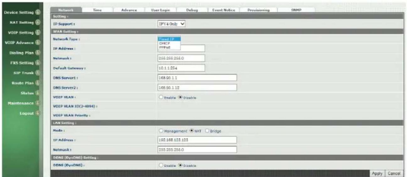
Figure 1-6-2 Network configure-1
Change Default IP Network:
Step 3: After successfully logon to the system, we need to change the network configuration. Click Device Setting > Network to setup the service network interface (WAN) parameters. Enter the deserved IP address, netmask and default gateway or selected to "DHCP" or "PPPOE". Apply the change by
clicking Apply button as fig (See Figure 1-6-3 Network configure-2).
Note: If Gateway WAN port are setting in the 10.x.x.x segment, please make sure that you also change the LAN port to other segment such as 192.168.x.x
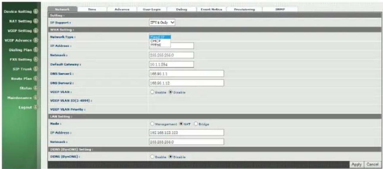
Figure 1-6-3 Network configure-2
Change Default Time setting:
Step 4: When re-logon to the new IP address, the next is to setup the system time zone. Click Device Setting > Time to setup the system. Enter the current SNTP server, time zone and daylight saving parameters. Apply the change by clicking Apply button. (See figure 1-6-4 Time setting)
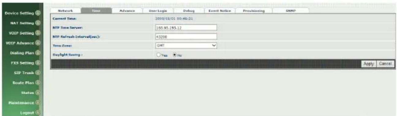
Figure 1-6-4 Time setting
Modify SIP Account Parameter:
Step 5: The next step is to add a SIP trunk for VOIP calling. For Wellgate 2540, it is necessary for VOIP calling while wellgate 2504 is optional. Click SIP trunk and new to create the required sip trunk. Enter the trunk ID to 1 and
input those SIP parameters. Apply the change by clicking Apply button. (See Figure 1-6-5 SIP Trunk).
Note: please don't delete sip trunk, even it is not be used, because it have to be used with Route plan.
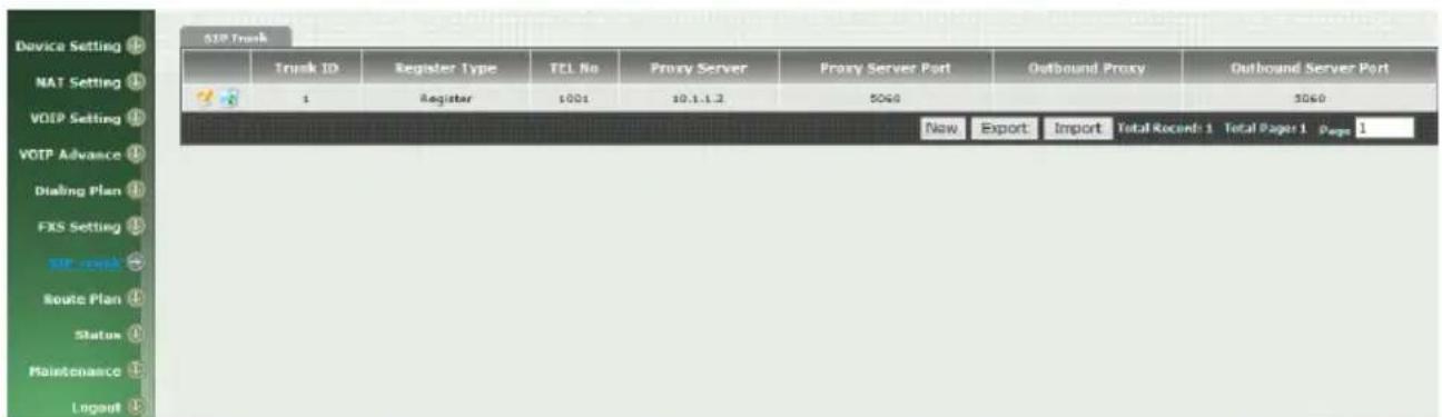
Figure 1-6-5 SIP Trunk
Modify FXS SIP Settings: (wellgate 2504 only)
Step 6: Set the SIP proxy server for FXS calling. For Wellgate 2504, the all FXS ports are using the same SIP proxy setting. If you need use different SIP proxy server, please use SIP trunk instead. Click FXS Settings > SIP Proxy to set the dedicate FXS SIP proxy server. (See Figure 1-6-6 SIP Proxy)
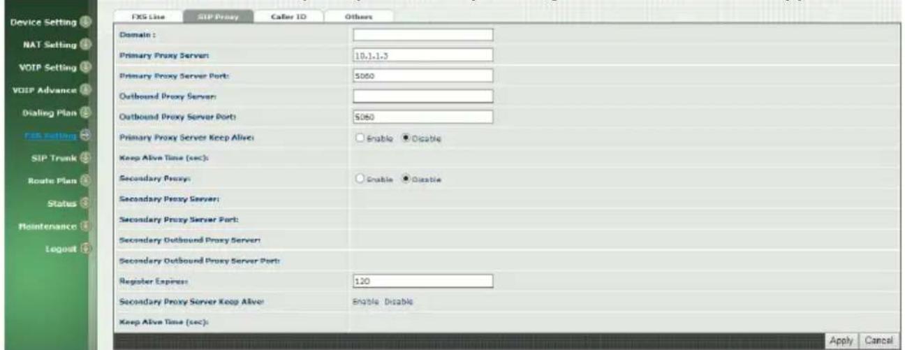
Figure 1-6-6 SIP Proxy
Step 7: Setup each FXS line's parameters by clicking the line ID from FXS settings > FXS Line. Modify the SIP register information and apply it. (See Figure 1-6-7 FXS Setting and Figure 1-6-8 Line setting)

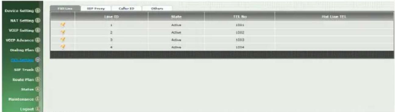
Figure 1-6-7 FXS Setting

Figure 1-6-8 Line Setting
Soft Reset Wellgate 2504:
Step 8: After modify basic setting. It is required to reset Wellgate 2504. Click Maintenance > Maintenance > Quick-Reset or Reboot to take effect. Apply the change by clicking Apply button. (See Figure 1-6-9 Quick-Reset)

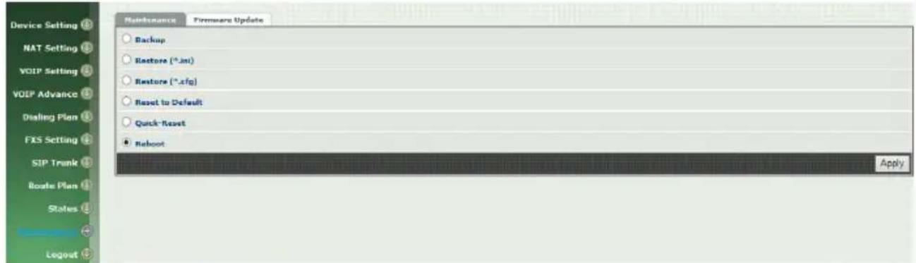
Figure 1-6-9 Quick-Reset
Check Wellgate 2504 Registered Status:
Step 9: After Quick-Reset or reboot.
Click Status > SIP Trunk Status to check whether registered or not. (See Figure 1-6-10 SIP Trunk Status)
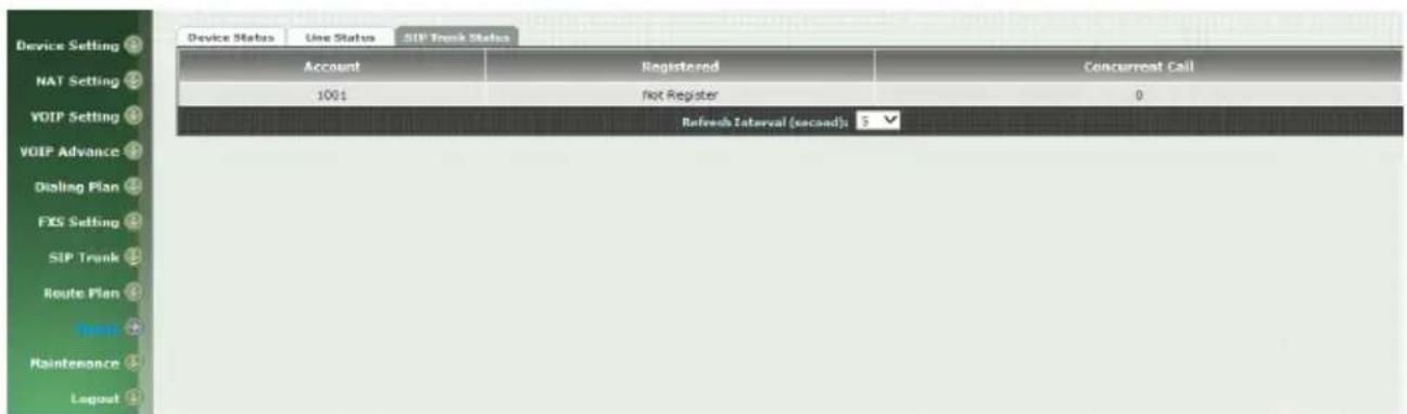
Figure 1-6-10 SIP Trunk Status
Click line status to check whether registered or not. (Figure 1-6-11 Line Status)
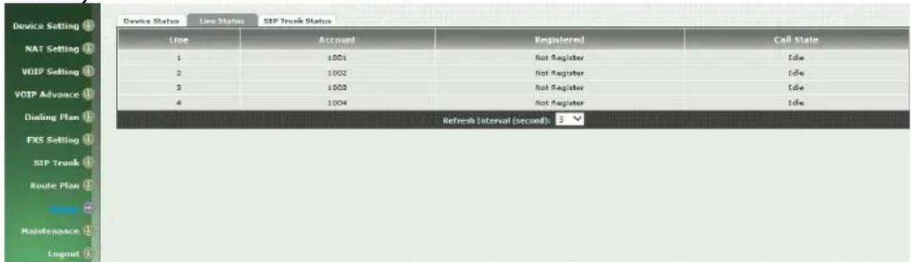
Figure 1-6-11 Line Status
Through the above settings, the Wellgate 2504 should able to do the following:
For FXS (WG2504):
- The user can pick up the handset and hear dial tone. Call out and talk.
- For VOIP incoming call to a dedicate FXS number, the dialed phone will ring and can answer to talk.
CH2 Device Settings
From this setting category, all devices related parameters can be found here.
2-1 Network Configuration
> Network
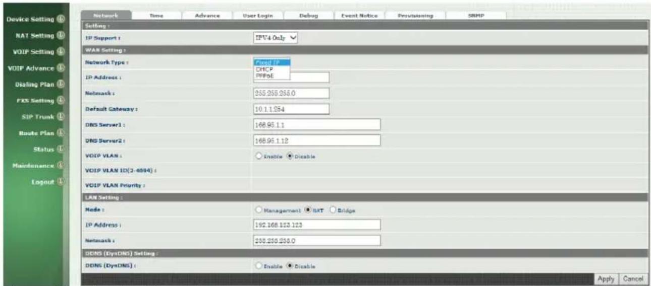
Figure 2-1 network setting
Parameter Description:
WAN Setting:
- Network Type: support "Fixed IP"; "DHCP"; "PPPOE"
- IP Address: IP address
- Default Gateway: Default gateway
- DHCP Tag (option 60): input Vendor class identifier or not.
- DHCP Tag (option 61): input Client identifier or not.
- DNS Server1: Primary DNS Server IP network
• DNS Server2: Secondary DNS Server IP network - VOIP VLAN: Enable VOIP VLAN or not. When enable VOIP VLAN, the WAN port can be only accessed by VLAN. If it is required to manage the Wellgate 2504, Administrator can use LAN port instead.
• VOIP VLAN ID(2-4096): VLAN ID Used
Note: the default WAN IP address is 10.1.1.3.
LAN Setting:
● Management mode: This LAN port is used for management purpose, not used for register or routing.
- NAT mode: DHCP function on the LAN port. The LAN ports will function as a DHCP server, network devices connected to them will be issued with IP addresses. (On the lift item will add a NAT setting, the information please refer NAT setting)
- IP Address: IP address (please set to 192.168.x.x if your WAN port is using 10.x.x.x IP segment).
- Netmask: IP network mask
- Bridge mode: At this mode, both WAN and LAN ports are configured to Switch/Hub features. LAN port access to WAN port directly.
Note: default LAN IP address is 192.168.123.123
DDNS (DynDNS) Setting:
- DDNS (DynDNS): enable or disable dynamic DNS feature.
- Domain Name: input your Domain Name
- User Name: input your user name
- Password: input your password
2-2 Device Time Setting
Wellgate 2504 support SNTP with time zone and daylight saving.
Device Setting > Time
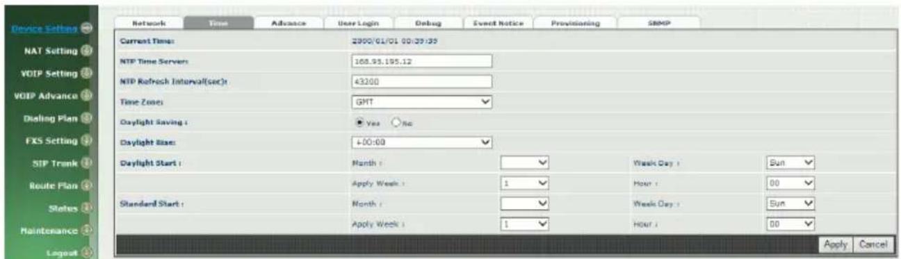
Figure 2-2 Time setting
Parameter Description:
- Now: Current Time (display only)
• NTP Time Server: SNTP time server - NTP Refresh Interval(sec): The frequency to sync NTP server in seconds
• Time Zone: The time-zone Wellgate 2504 is located.
◆ Standard: Use a predefined standard time zone
◆ Customize: Use a user defined time zone
● Daylight Saving: Auto adjust daylight saving timer or not
● Daylight Bias: The offset added to the Bias when the time zone is in daylight saving time
● Daylight Start: The date that a time zone enters daylight time
◆ Month: 01 to 12
◆ Week Day: Sunday to Saturday
◆ Apply Week (Day:01 to 05, Specifies the occurrence of day in the month; 01 = First occurrence of day, 02 = Second occurrence of day, ...and 05 = Last occurrence of day)
◆ Hour: 00 to 23
- Standard Start: The date that a time zone enters daylight time
◆ Month: 01 to 12
◆ Week Day: Sunday to Saturday
WELLTECH
◆ Apply Week (Day:01 to 05, Specifies the occurrence of day in the month; 01 = First occurrence of day, 02 = Second occurrence of day, ...and 05 = Last occurrence of day)
◆ Hour: 00 to 23
2-3 Device Advance Setting
> Advance
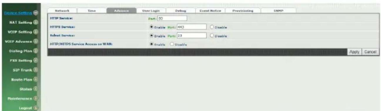
Figure 2-3 Advance setting
Parameter Description:
- HTTP Service: The Administrator Web service port (the default is 80)
- HTTPS Service: The https web service port (the default is 443)
- Telnet Service: The telnet service port (the default is 23)
- HTTP/HTTPS Service access on WAN: When click the disable option; The WEB service will be rejected on WAN port, so please be careful with this function. If you wanted to enable WAN port again, you need to access this device from its LAN port to connect to WEB pages and enable WAN port.
2-4 User Login Setting
Three level of users can be used, administrator, supervisor, user. Each level of users will have different predefined access level.
>User Login
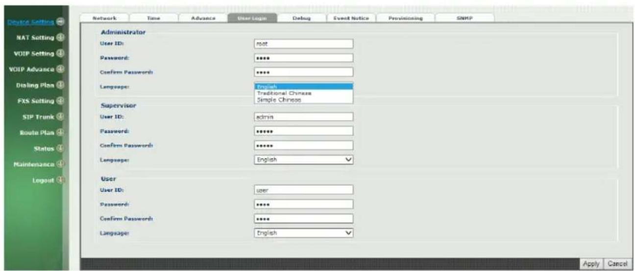
Figure 2-4 user login setting
Parameter Description:
- Administrator: The administrator level user which has full access of Wellgate 2504.
- Supervisor: The supervisor level user which has limited administrative access right.
- User: The user access right which only allows to setting some user related features.
- User ID: Login User ID
- Password: Login Password
- Confirm Password: Confirm new password again
● Language: The web page language used when the account login. To add a customized local language, please contact Welltech.
2-5 Debug Settings
Wellgate 2504 provides the real time debug to syslog or through telnet interface. It generates the debug information based on debug level and modules. Since the generating debug will consume system resource, it is recommended to turn on only for necessary and under Welltech FAE's instruction.
Debug
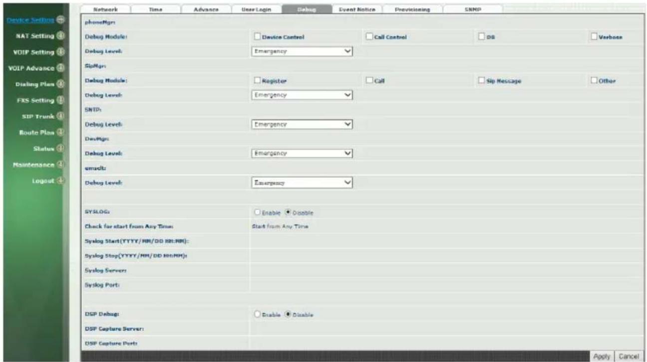
Figure 2-5 Debug setting
Parameter Description:
- SYSLOG: Enable or disable to send system information to SYSLOGD server or not
- Check for start from Any Time: Always Send: Always send syslog or only during a specified time range.
- Syslog Start (YYYY/MM/DD HH:MM): Always Send: Always send syslog or only during a specified time range.
- Syslog Stop (YYYY/MM/DD HH:MM): The syslog stop sending time.
- Syslog Server: Syslog server IP address
- Syslog Port: syslog server service port (default is 514)
- DSP Debug: Enable or disable to send DSP information to capture log
- DSP Capture server: Syslog capture server IP address
- DSP Capture port: syslog capture server service port (default is 50000)
2-6 Event Notice
Wellgate 2504 can send Syslog Event Notice when it had the following cases:
- FXO is plug or unplug
- Ethernet reconnected
-
System started
-
Register Failure or re-registered
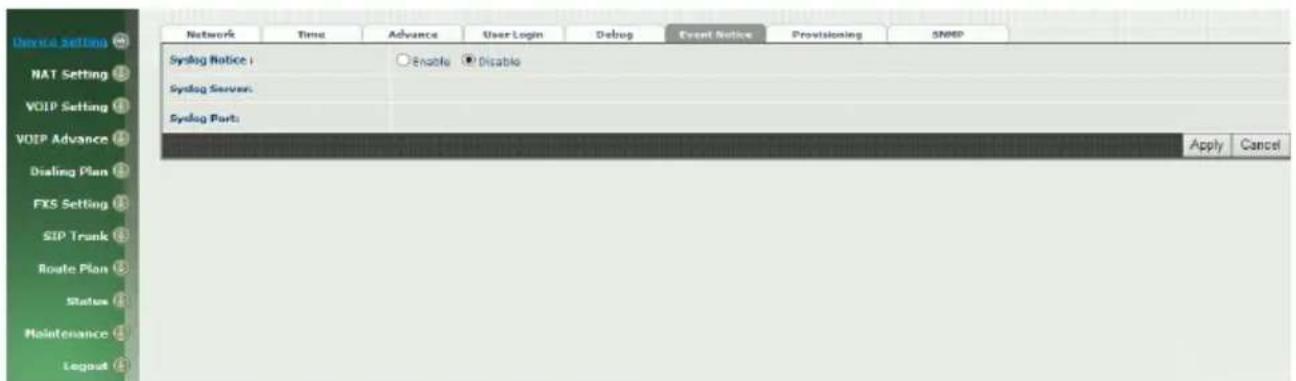
Figure 2-6 Event notice setting
- SYSLOG: Enable or disable to send system event to SYSLOG server or not
- Syslog Server: Syslog server IP address
- Syslog Port: syslog server service port (default is 514)
2-7 Auto Provisioning
The Wellgate 2504 can be provisioned by WellEMS 9510 for large deployment. Please contact Welltech for availabilities.
>Provisioning
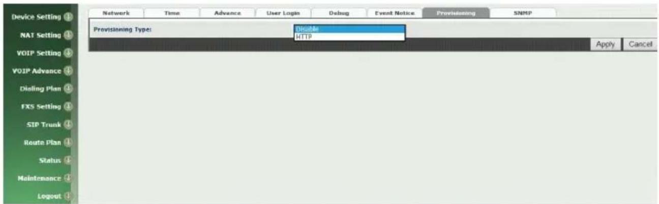
Figure 2-7-1 Provisioning
Select Http:
This feature is for feature usage only.
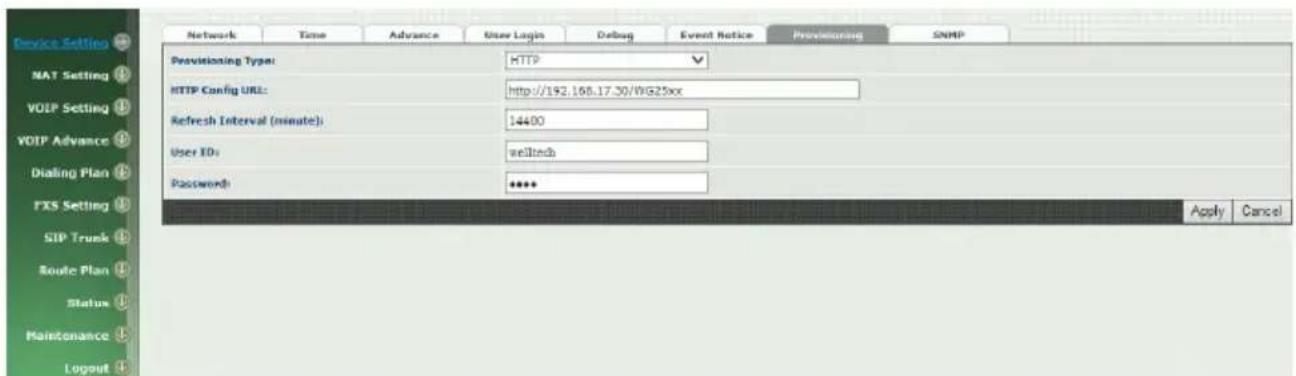
Figure 2-7-2 Provisioning type of Http
- Http config URL: internal used only
- Refresh interval(minute): interval to check whether have a new configuration/firmware or not in minutes
- User ID: specify the login id for http authentication
- Password: specify the password for http authentication
2-8 SNMP
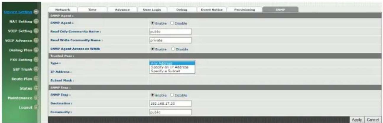
Figure 2-8 SNMP
SNMP Agent:
- SNMP Agent: Enable SNMP or not.
- Read Only Community Name: The community name to read through SNMP protocol
- Read Write Community Name: The community name to read and write through SNMP protocol.
- SNMP Agent Access on WAN: Enable SNMP to be accessed through WAN port or not.
Trusted Peer:
- Type:
◆ Any Address: Any address can retrieve the SNMP information.
◆ Specify an IP Address: Only the IP address listed can retrieve the SNMP information. Normally, it will be the SNMP manger IP address.
◆ Specify a Subnet: Only the network specified can retrieve the SNMP information.
- IP address: The IP address for a trusted peer
- Subnet Mask: The network mask for a trusted peer
SNMP Trap:
- SNMP Trap: Enable SNMP trap or not
- Destination: The IP address for SNMP manager to receive the SNMP trap
● Community: The communicate name for sending the SNMP trap
CH3 NAT Setting
The Wellgate 2504 can support NAT, 2 ethernet leg (gw) or bridge mode. Here are the settings for NAT related service.
3-1 DHCP Ser. (DHCP server)
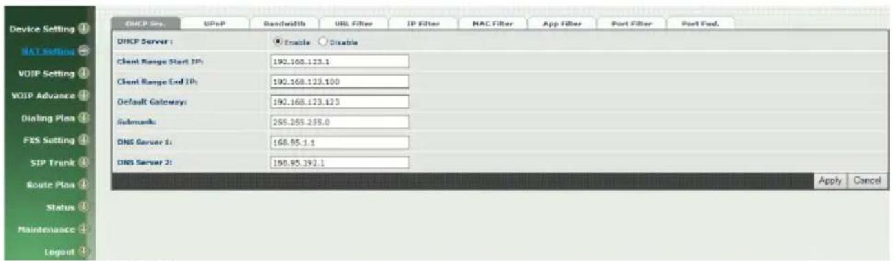
Figure 3-1 DHCP server
- DHCP Server: Enable DHCP server or not.
- Client Range Start IP: specify DHCP client lease start IP
- Client Range End IP: specify DHCP client lease end IP
- Default Gateway: specify the default gateway
- Submask: specify the submask.
• DNS Server 1: specify the DNS server
• DNS Server 2: specify the DNS server
3-2 UPNP (universal plug and play server)
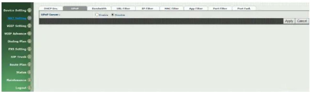
Figure 3-2 UPnP
- UPNP IGD: Enable UPNP server or not.
3-3 Bandwidth (Bandwidth Control)
By using bandwidth control feature, the user can manage the traffic based on their needs.
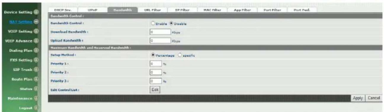
Figure 3-3-1 Bandwidth control
Bandwidth Control:
● Bandwidth Control: enable bandwidth control or not.
- Download Bandwidth: specify total bandwidth for download (unit: kbps). 0 indicates no limitation.
- Upload Bandwidth: specify total bandwidth for upload (unit: kbps). 0 indicates no limitation.
Maximum Bandwidth and Reserved Bandwidth:
- Setup Method: bandwidth control method, percentage or specify the required bandwidth
percentage : total bandwidth
◆ priority 1: highest priority percentage
◆ priority 2: Normal priority percentage
◆ priority 3: low priority percentage
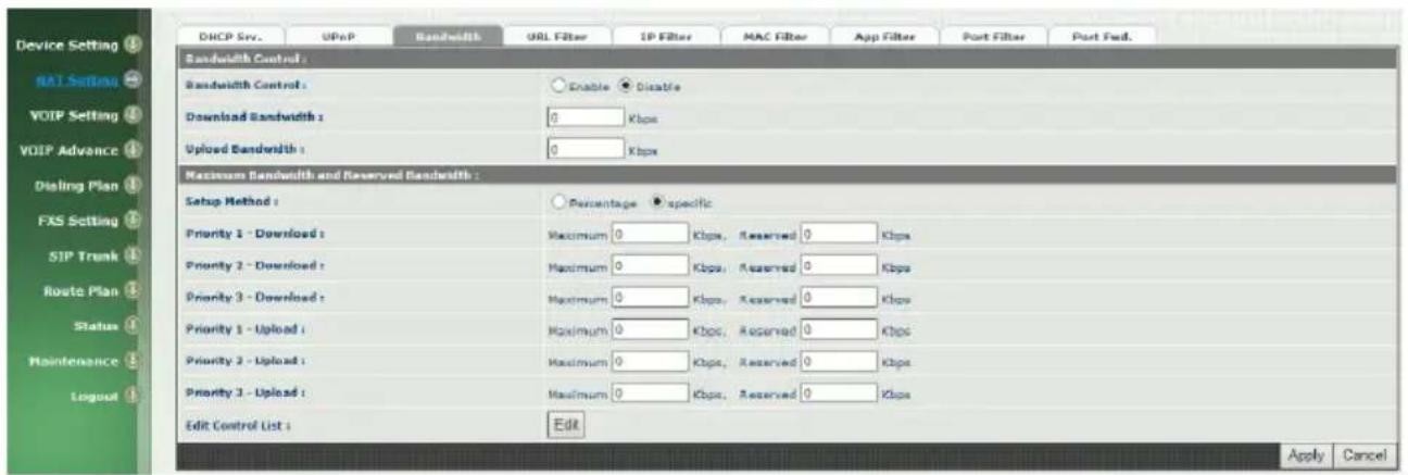
Figure 3-3-2 Bandwidth control
specific :
◆ priority 1 – Download: highest priority download bandwidth
◆ priority 2 – Download: normal priority download bandwidth
◆ priority 3 – Download: low priority download bandwidth
◆ priority 1 – Upload: highest priority upload bandwidth
◆ priority 2 – Upload: normal priority upload bandwidth
◆ priority 3 – Upload: low priority upload bandwidth
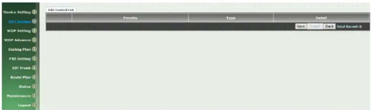
Figure 3-3-3 Edit control list
In order to set which target is belonged to which priority, the following is the setting method for target's priority.
IP Target
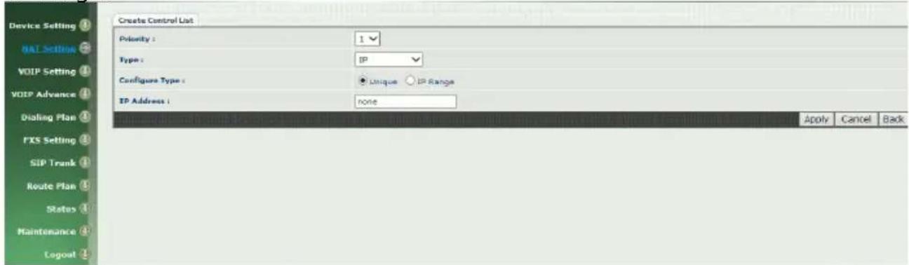
Figure 3-3-4 IP Target 1
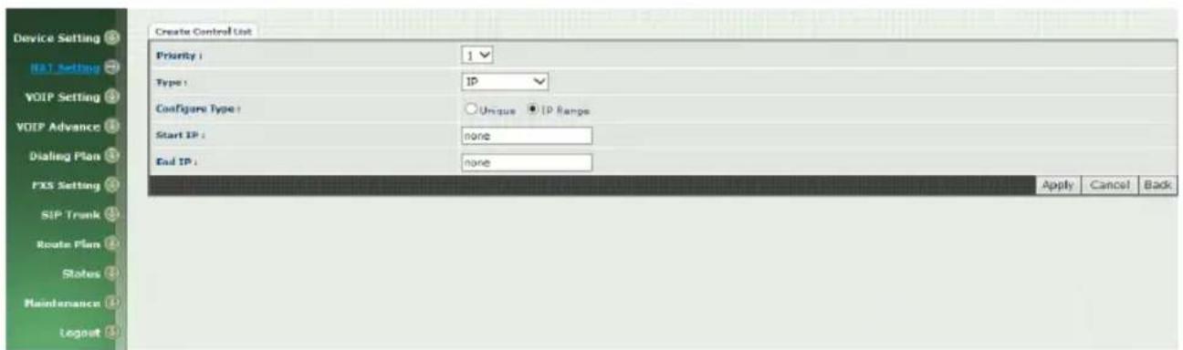
Figure 3-3-5 IP Target 2
● Priority: Priority value for the target
- Type: The target type is set to IP
- Configure Type: unique IP or a range of IP address
Unique:
◆ IP Address: the IP address to be set
IP Range:
◆ Start IP: The starting IP for a range
◆ End IP: The stopping IP for a range
Port Target
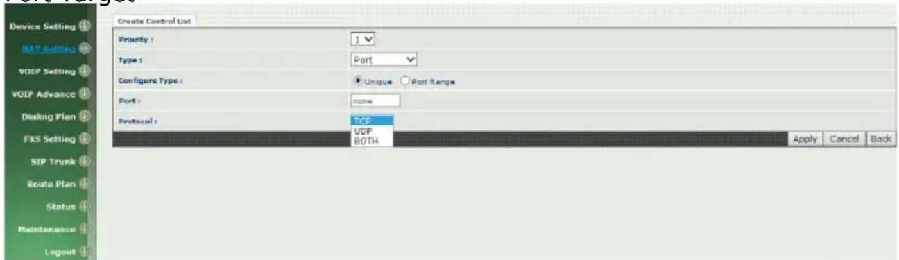
Figure 3-3-6 Port Target
● Priority: Priority value for the target
- Type: The target type is set to port number
- Configure Type: unique port number or a range of port number
Unique:
◆ Port: the port number to be added
◆ Protocol: protocol for the port
Port Range:
◆ Start port: the starting port number
◆ End port: the stop port number
◆ Protocol: protocol for the port range
Application Target
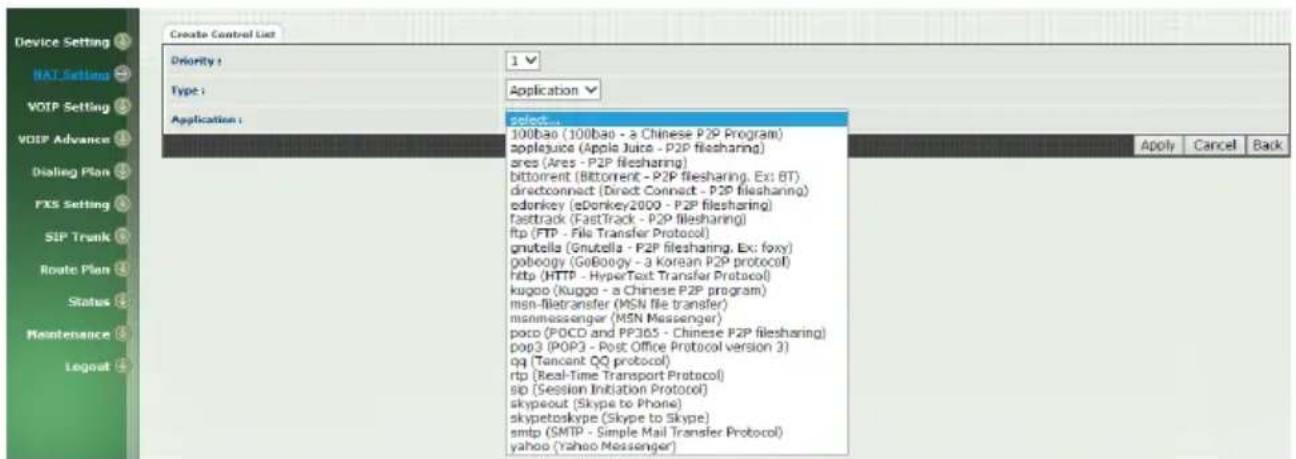
Figure 3-3-7 Application Target
● Priority: Priority value for the target
- Type: Application
- Application: the list for the application
DSCP target
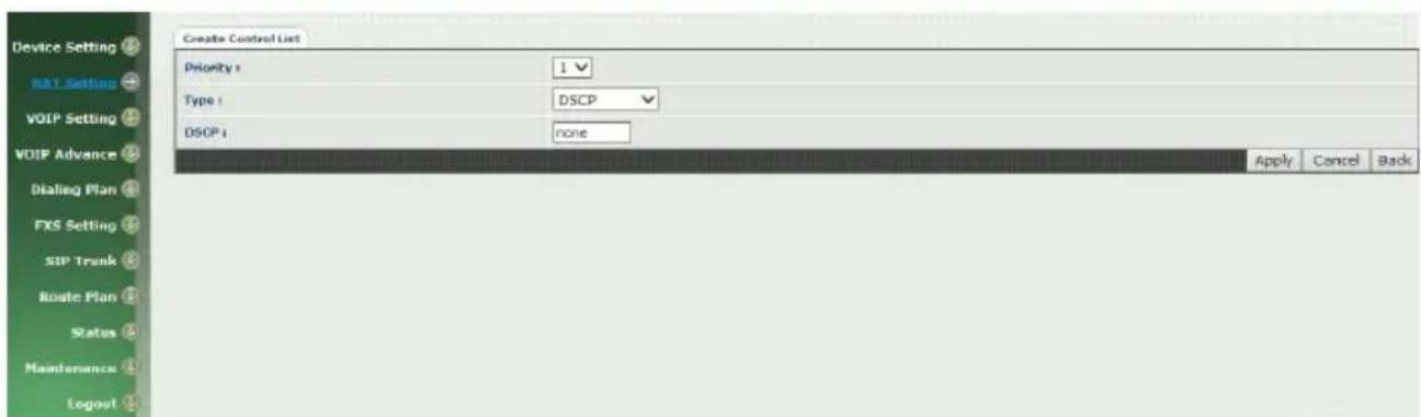
Figure 3-3-8 DSCP Target
● Priority: Priority value for the target
- Type: DSCP value
● DSCP: The DSCP will be mapped to the priority
The Wellgate 2504 support firewall features as below.
3-4 URL Filter
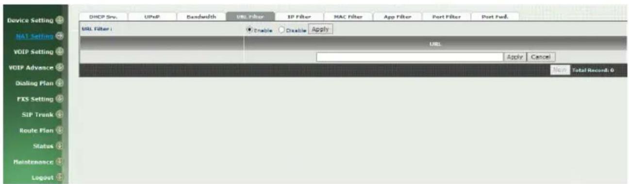
Figure 3-4 URL Filter
- URL Filter: the specified url will be blocked
3-5 IP Filter
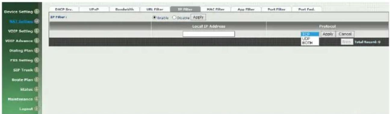
Figure 3-5 IP Filter
- IP Filter: The specified IP address to be blocked
- Local IP address: The LAN side IP address to be forwarded
- Protocol: TCP, UDP or both are used for port forward
3-6 MAC Filter
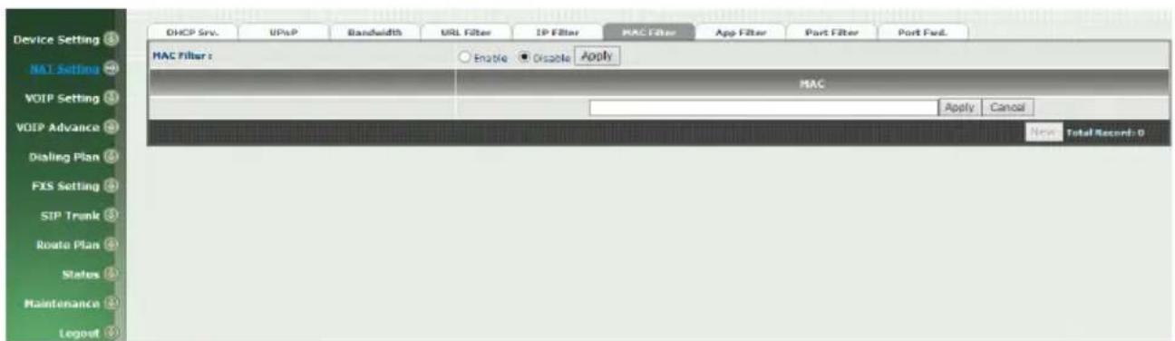
Figure 3-6 MAC Filter
- MAC Filter: The MAC address to be blocked
3-7 APP Filter
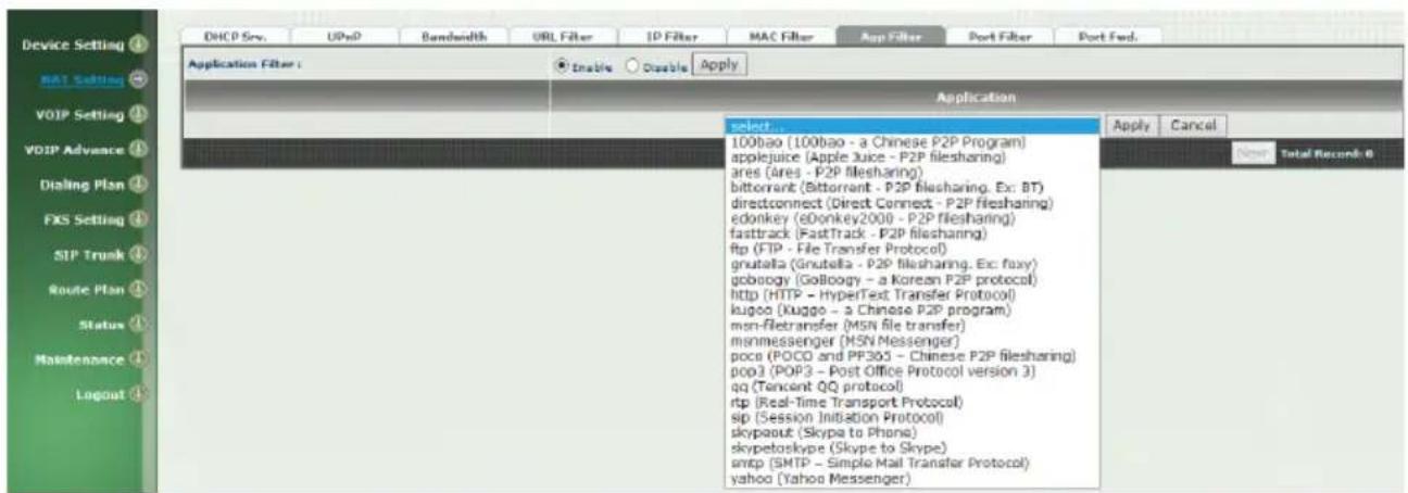
Figure 3-7 App Filter
- APP Filter: application to be blocked
3-8 Port Filter
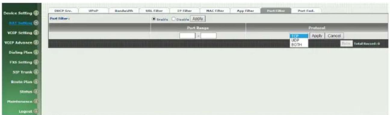
Figure 3-8 Port Filter
- Port Filter: enable port Filter or not.
- Port Range: Starting and stopping port to be forward. If you are using only 1 port, please set the starting equal to stopping port.
- Protocol: TCP, UDP or both are used for port blocked.
3-9 Port Fwd
The wellgate 2504 support port forward feature as below
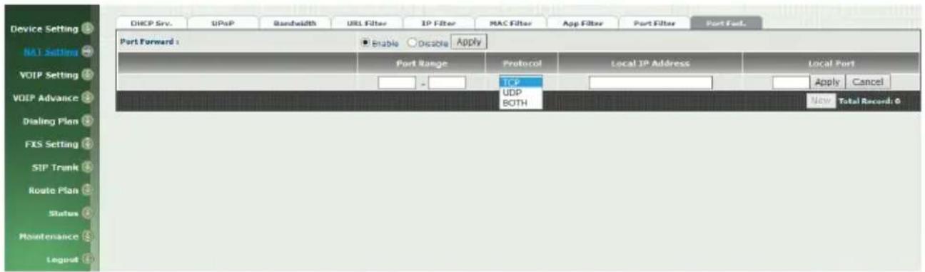
Figure 3-9 Port Fwd
- Port Fwd: enable port forward feature or not
- Port Range: Starting and stopping port to be forward. If you are using only 1 port, please set the starting equal to stopping port.
WELLTECH
- Protocol: TCP, UDP or both are used for port forward
- Local IP address: The LAN side IP address to be forwarded
- Local Port: The LAN side port to be forwarded. If you are using the port range, this port indicates the starting port.
4-1 SIP
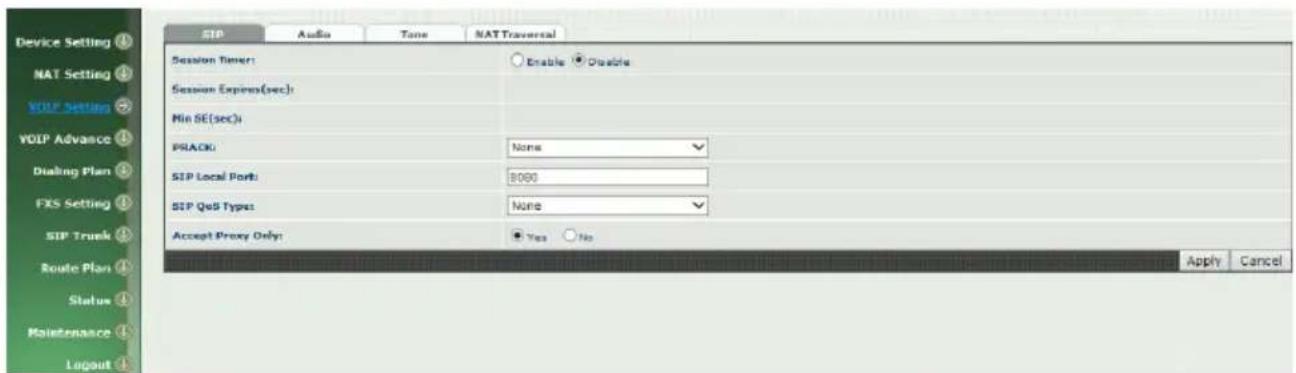
Figure 4-1 SIP setting
Parameter Description:
- Session Timer: Enable session timer or not (RFC 4028)
- Session Expires (sec): This is the setting of initial session timer expires time according to RFC4028 - Session Timers in the Session Initiation Protocol.
- Min SE (sec): The minimum session timer allowed when receiving a call with session timer value according to RFC 4028.
● PRACK: Enable provisioning ACK or not (RFC 3262)
◆ None: Disable PARCK
◆ Supported: When select this mode, 100rel will be added to the support list. It indicates Wellgate 2504 can support the PRACK but not mandatory.
◆ Require: PRACK is mandatory required. - SIP Local Port: The SIP local service port (default is 8080)
- SIP Qos Type: Quality of Service Type for SIP signaling
- None: Not using QOS Tag and not enables QOS.
- DiffServ: Differentiated Services Value. Input DSCP value 0-63 for DSCP
- TOS: Type of Service which include IP precedence value and TOS.
- Accept Proxy Only: Only accept the call coming from the SIP proxy. Not accept peer to peer call at this mode.
4-2 Audio
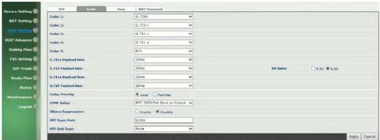
Figure 4-2 Audio setting
- Codec 1\~5: The preferred codec priority
● G.711u Payload Size: G.711 u-Law payload size
● G.711a Payload Size: G.711 A-law payload size
● G.729 Payload Size: G.729A payload size
● G.723.1 Payload Size: G.723.1 payload size
● Bit Rate: G.723.1 bit rate used
◆ 5.3K bit rate is used
◆ 6.3K bit rate is used
- Codec Priority: Selection order to match the remote SDP for codec selection.
Local SDP Order: Use local SDP order to match codec Remote SDP Order: Use Remote SDP order to match codec
- DTMF Relay:
In-Band DTMF: use inband DTMF instead of out of band.
RFC 2833(fall back to SIP-INFO): Use RFC 2833 if the SDP negotiation could be done. Or use SIP INFO for DTMF relay.
SIP INFO: Use SIP-INFO DTMF relay
RFC 2833(fall back to Inband): Use RFC 2833 if the SDP negotiation could be done. Or use inband DTMF transmission.
- Silence Suppression:
Enable: Start the voice activity (silence) detection when detect silence for 60 seconds, it will hang up the call (For FXO use)
Disable: Send silence packet as normal voice packet (no silence detection)
- RTP Basic Port: The RTP starting port. Each channel will be add additional 10. For example, the RTP basic port is 16384, thus call 1 will use 16384 while call 2 will use 16394 etc.
● RTP Qos Type: IP QoS tag for RTP stream
DiffServ: The differentiated service QoS tag will be used. Input DSCP value 0-63 for DSCP.
TOS: Type of Service which include IP precedence value and TOS.
4-3 Tone
The setting page is used to setup the tone to be generated or detected. The detected tone is the Disconnect 1 & 2 (for FXO use) and the others are for generating (when FXS received the "bye" from IP side or waiting time out by analog phone which keeps handset pick up, it will send busy tone to analog phone). The disconnect tone is very important for PSTN status supervision.
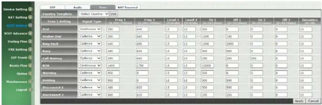
Figure 4-3 Tone setting
Please use Country Template to select the country profile which will be applied. Click Use to load those country tone parameters to system and change if necessary. For those countries are not showed in the list, please select a closed country and edit to match your country. You can send an email with the tone definition to Welltech if you would like to put your country into the list.
4-4 NAT Traversal
The Wellgate 2504 support the following NAT traversal methods
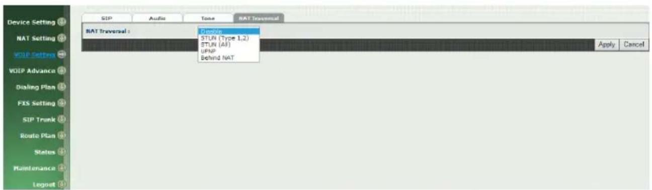
Figure 4-4 NAT Traversal
- NAT Traversal:
◆ Disable: Disable NAT traversal features
◆ STUN (Type 1,2): Enable STUN for NAT traversal. Since STUN can be used only for type 1 and type 2 NAT server, it is recommended to use this option. When STUN client detect the used NAT is type 3 NAT, it will stop the STUN feature.
✨ STUN Server: STUN Server IP address
◆ STUN (All): No matter which NAT type server are used, STUN is always to be used for NAT traversal.
✨ STUN Server: STUN Server IP address
◆ UPNP: Enable UPnP client for NAT traversal. Please note that the IP sharing box need support uPnP feature.
◆ Behind NAT: Use DMZ for NAT traversal
IP Sharing Address: public IP sharing address. You need to specify the port mapping or DMZ for all required port.
CH5 VOIP Advance
5-1 SIP
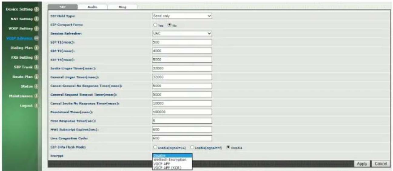
Figure 5-1 SIP
Parameter Description:
- SIP Hold Type: SIP on hold message sending method.
- Send Only: Set the SDP media to sendonly when send an on-hold SIP message.
- 0.0.0.0: Set the SDP connection to 0.0.0.0 when send an on-hold SIP message.
- Inactive: Set the SDP media to inactive when send an on-hold SIP message.
- SIP Compact Form: Enable SIP compact form or not. When enable this feature, the connected SIP proxy is required to support compact form.
- Session Refresher: Who will send dialog keep alive message (re-invite or update).
◆ UAC: User Agent Client will do the refresh (default setting)
◆ UAS: User Agent Server will do the refresh
- SIP T1 (msec): T1 determines several timers as defined in RFC3261. For example, when an unreliable transport protocol is used, a Client Invite transaction retransmits requests at an interval that start at T1 seconds and doubles after every retransmission. A
Client General transaction retransmits requests at an interval that starts at T1 and doubles until it reaches T2. (Default Value: 500ms) **
- SIP T2 (msec): Determines the maximum retransmission interval as defined in RFC3261. For example, when an unreliable transport protocol is used, general requests are retransmitted at an interval which starts at T1 and doubles until reaches T2. If a provisional response is received, retransmission continue but at an interval of T2. (Default Value: 4000ms) **
- SIP T4 (msec): T4 represents the amount of time the network takes to clear message between client and server transactions as defined in RFC3261. For example, when working with an unreliable transport protocol, T4 determines the time that UAS waits after receiving an ACK message and before terminating the transaction. (Default Value: 5000) **
- Invite Linger Timer: After sending an ACK for an INVITE final response, a client cannot be sure that the server has received the ACK message. The client should be able to retransmit the ACK upon receiving retransmissions of the final response for this timer. This timer is also used when a 2xx response is sent for an incoming Invite. In this case, the ACK is not part of the Invite transaction.
- General Linger Timer: After a UAS sends a final response, the UAS cannot be sure that the client has received the response message. The UAS should be able to retransmit the response upon receiving retransmissions of the request based on this timer.
- Cancel General No Response Time (msec): When sending a CANCEL request on a General transaction, the User Agent waits cancel General No Response Timer milliseconds before timeout termination if there is no response for the cancelled transaction(Default Value: 10000ms).**
- General Request Timeout Timer (msec): After sending a General request, the User Agent waits for a final response general Request Timeout Timer milliseconds before timeout termination (in this time the User Agent retransmits the request every T1, 2*T1,...T2,...milliseconds)**
- Cancel Invite No Response Timer (msec): When sending a CANCEL request on an Invite request, the User Agent waits this timer before timeout termination if there is no response for the cancelled transaction.
- Provisional Timer (msec): The provisionalTimer is set when receiving a provisional response on an INVITE transaction. The transaction will stop retransmissions of the INVITE request and will wait for a final response until the provisionTimer expires. If you set the provisionTimer to 0, no timer is set. The INVITE transaction will
wait indefinitely for the final response.
- First Response Timer (msec): When sending a request out, the User Agent waits this timer for any response received from UAS. If timer is expired and no any SIP message is received, the User Agent will think the request is failed. The default is 5 seconds.
- MWI Subscript Expires (sec): You can Enable or Disable the MWI subscribe. The default is 600 sec. If a new voice mail is arrived, the stutter tone will be used instead of regular dial tone. This feature is dedicate to FXS only.
- Line Congestion Code: when callee's end system was contacted successfully but the callee is busy and does not wish to take the call at this time, the system wills response the code, default is 600. (FXO use)
- SIP-Info Flash Mode: when you enable the feature, system will make flash key to send SIP message by sip-info.
◆ Signal=16: send signal 16 on info message.
◆ Signal=hf: send signal hf on info message.
◆ Disable: disable this function.
- Encrypt:
◆ Disable: disable encryption function.
- Welltech encryption: Enable Welltech proprietary encryption for SIP signaling and RTP. It is required a Welltech SIP proxy server (WS6500 or SIPPBX 6200) to work with this feature. When enable it, you can hide your VOIP traffic from ISP's monitor.
◆ VGCP APP: supports VGCP APP type.
◆ VGCP APP (XOR): supports VGCP APP XOR type.
5-2 Audio
The setting page includes the device related audio settings.
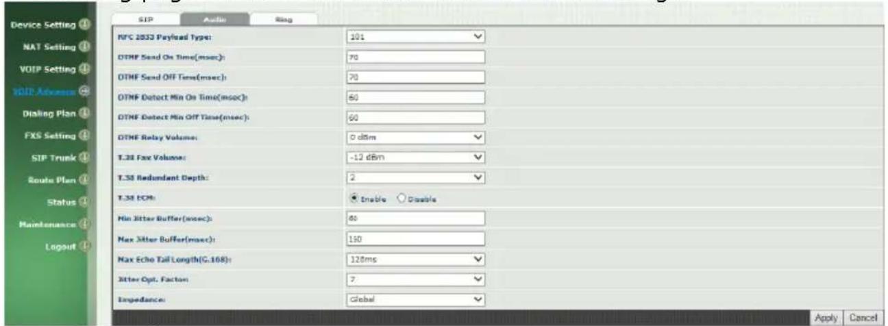
Figure 5-2 Audio setting
- RFC 2833 Payload Type: 96 or 101. It is recommended to use 101.
- DTMF Send On Time(msec): When generate DTMF, the DTMF on time will be send (default value is 70 ms)
- DTMF Send Off Time(msec): When generate DTMF, the DTMF off time will be send (default value is 70 ms)
- DTMF Detect Min on Time (msec): The minimum DTMF on time will be processed as a regular DTMF event. Smaller than it will be ignored. The default value is 60ms.
- DTMF Detect Min off Time (msec): The minimum DTMF off time for the same DTMF value. Smaller than it and the new DTMF digit is the same as previous one will be handled as 1 digit only.
- DTMF Relay Volume: The DTMF relay volume
● T.38 Fax Volume: The T.38 fax relay volume - T.38 Redundant Depth: The T.38 redundant packet depth. It could 0 (no redundant), 1 or 2. It is recommended to set to 2.
- T.38 ECM: The t.38 error correction mode. Default value is ON.
- Min Jitter Buffer (msec): The minimum delay time of Jitter buffer.
- Max Jitter Buffer (msec): The Maximum delay time of Jitter buffer. The maximum is "300ms"
- Max Echo Tail Length (G.168): Enable the echo cancellation feature. The default setting is "128ms".
- Jitter Opt. Factor: Jitter buffer dynamic factor for optimize. Please set to 7 unless under Welltech's instruction to change.
- Impedance: selected analog phone's impedance. (for FXS port use)
5-3 Ring
The ring cadence, voltage and frequency for the phone
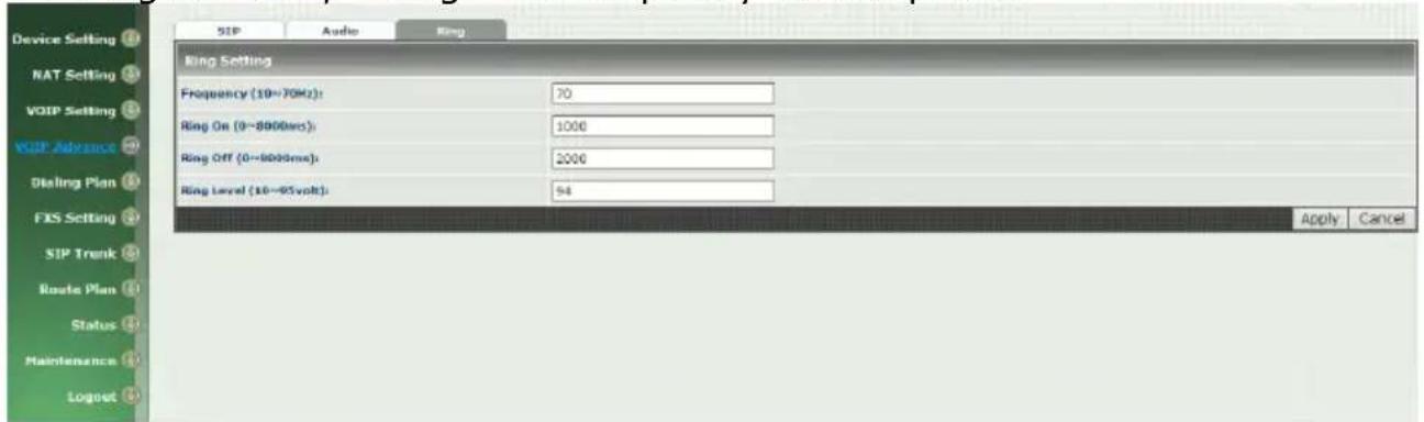
Figure 5-3 Ring setting
◆ Frequency (10\~70HZ): Specify the ringing frequency value (default is 20HZ)
◆ Ring on (0\~8000ms): Specify the ringing on value (default is 1000msec)
◆ Ring off (0\~8000ms): Specify the ringing off value (default is 2000msec)
◆ Ring level (10\~95volt): Specify the ringing level (default is 94 volt)
CH6 Dialing Plan
6-1 General
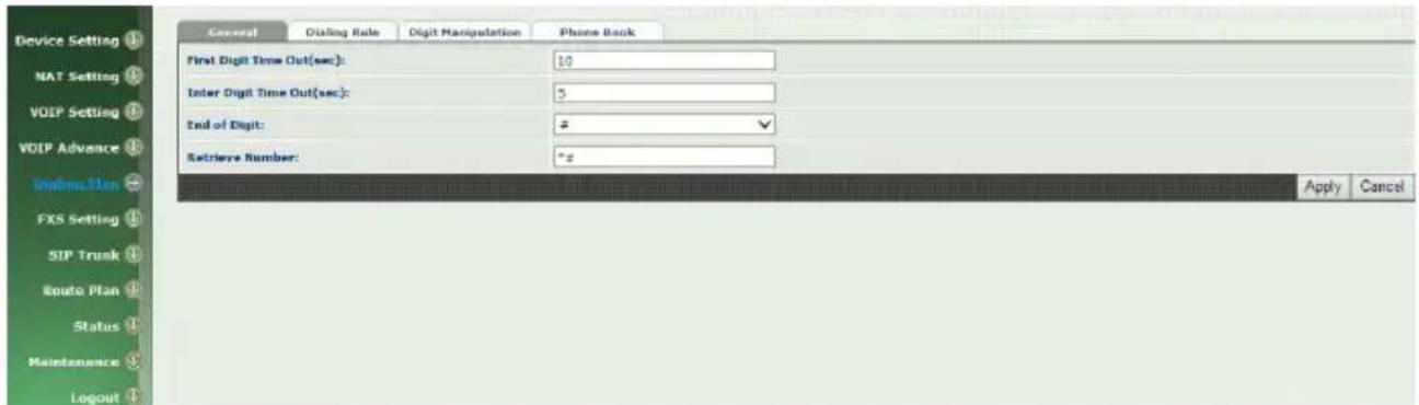
Figure 6-1 General setting
- First Digit Time Out: Specify the duration of dial waiting when the receiver is off hook. The range is 1\~60 sec.
- Inter Digit Time Out: Specify the interval of input digits, if the interval is over the setting, the system will end the dial and send out the DTMF. The limitation range is 1\~10sec.
- End of Digit: The assigned key will be tread as end of dial.
- Retrieve Number: it will forced to get back line, if used Wellgate 2504 make transfer to other devices but the devices no answer and into voice mail,
You can press the code forced to get back line. Default is "*#".
6-2 Dialing Rule
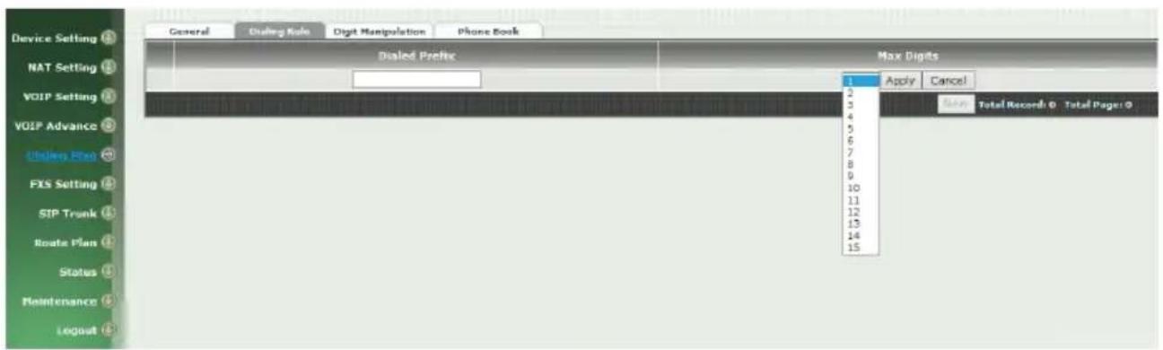
Figure 6-2 Dialing Rule setting
Dialing rule is used to speed up the dialing procedure. Some user don't like to use the end of dialing digit such as “#”, the administrator can use dialing rule instead. The longest prefix will be matched first.
- Dialed Prefix: The prefix to be matched
● Max Digits: The digits will be received based on the Dialed Prefix.
The following is an example for dialing rule:
Mobile call is started with 09 and it is 10 digits
Long distance call is started with 0 and it is 10 digits
International call is started with 00 and its max digit should be less than 32. The others are local call and 8 digits
Emergency call is started with 1 and 3 digits
The Dialing rule can be set as follows:
Prefix, max digits
09, 10
0, 10
00, 15
1,3
2,8
3,8
4,8
5,8
6,8
7,8
8, 8
9,8
6-3 Digit Manipulation
The Digit Manipulation will be processed based on prefix and DM group after the DNIS is determined.
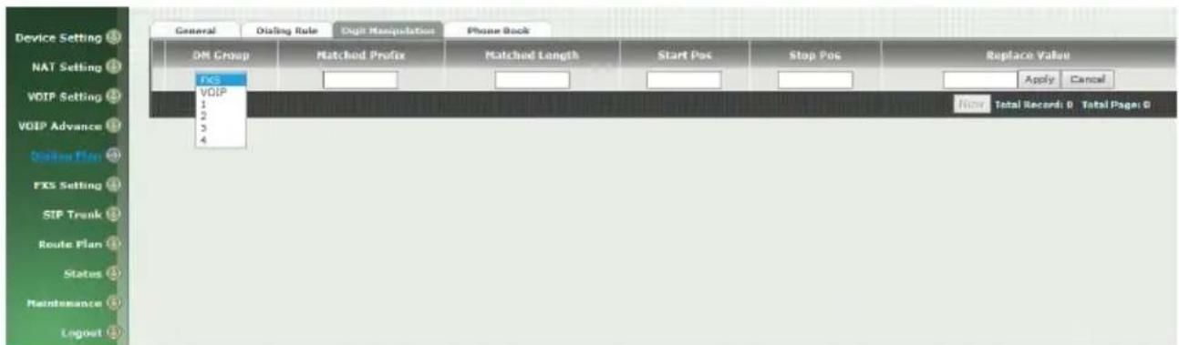
Figure 6-3 Digit Manipulation setting
● DM Group: Different DM group have different case to be used.
◆ FXS: This DM group is used for FXS dialing out.
◆ VOIP: This DM group is used for VOIP incoming call. After the DNIS is collected in 2 stage dialing or 1 stage dialing DNIS, this DM group will be processed before enter the routing procedure.
◆ 1-4: These DM groups are used for backup routing purpose. When a backup routing is used, the administrator can select a DM group to be processed before start the backup route.
- Matched Prefix: The prefix to be matched for DM. The longest prefix will be matched first.
- Matched Length: Set to 0 for ignoring the length. The other 1-32 are the length to be matched as a condition.
- Start Pos: The start position to be replaced.
- Stop Pos: The stop position to be replaced.
- Replace Value: The value to replace.
Example of Digit Manipulation Settings:
| Prefix | Len | Start Pos | Stop Pos | Replace Value | Test DNIS | Result DNIS |
| 886 | 0 | 0 | 0 | 002 | 8862123456 | 0028862123456 |
| 886 | 12 | 0 | 0 | 002 | 8862123456 | 8862123456 |
| 886 | 0 | 2 | 5 | 002 | 8862123456 | 8800223456 |
| 886 | 0 | 30 | 30 | 002 | 8862123456 | 8862123456002 |
| 886 | 0 | 1 | 6 | 8862123456 | 83456 |
Note: The DM Group 1\~4 can have the feature to delay the dialing by added a "p" into the replace value. It might be useful, if you want to wait for a while and dial the second part of DTMF for calling out. Each "p" represents 1 seconds delay. For example: 822265699ppp1234; it will first dial 82265699 and wait to 3 sec to dial 1234.
6-4 Phone Book
Phone Book is used for peer to peer call.
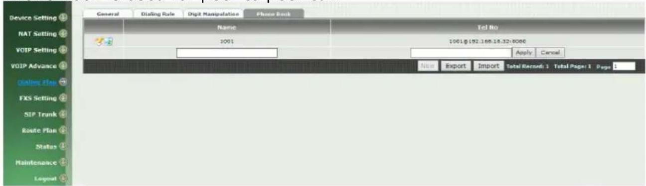
Figure 6-4 Phone Book setting
- Name: This field supports called number only. If you enter words or text here, it will routes to proxy server automatically.
- Tel No: Enter called number and IP address. Please follow this sample of picture, as the format of "number@uri:port". (default port is 5060)
- Export: To backup the phone book records.
- Import: To reload setting of phone book.
CH7 FXS Setting
The FXS line setting includes each line number and SIP proxy settings.
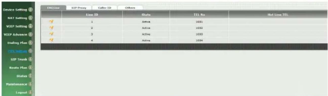
Figure 7-0 FXS setting
• Line ID: FXS line (TEL1 to TEL4)
● State: The line is active or not
- TEL No: The telephone number
● Hotline TEL: If hot line is set, this field shows the hot line number.
7-1 FXS line
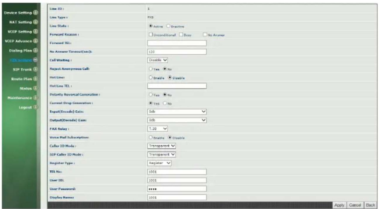
Figure 7-1 FXS setting
- User ID: FXS Line number (TEL1 to TEL4)
- User Type: The line type, FXO or FXS
- Line State: Set to active if you would like to use this line. Otherwise, set to Inactive.
- Forward reason:
◆ Unconditional forward: forward the call all the time
◆ Busy forward: Forward the call when phone is busy.
◆ No answer forward: forward the call when the call does not answered after no answer timeout.
◆ Forward TEL: The forward telephone number for the selected reason
- No answer timeout: sec The no answer timeout will be used (default is 120 sec)
- Call waiting: Enable call waiting or not. When disable call waiting features, the second incoming call will be rejected.
- Reject Anonymous Call: Reject the anonymous incoming call or not
● Hot line: Enable to disable hot line feature
● Hot line TEL: The number to be dialed automatically after the user pickup the phone.
WELLTECH
- Polarity Reversal generation: Enable Polarity Reversal for FXS as billing signal or not. When a FXS calls to VOIP and answered by the VOIP, Wellgate 2504 will generate reverse signal to FXS as a billing start. When VOIP side disconnect first, Wellgate 2504 will reverse back as a billing stop signal.
- Current Drop generation: Enable current drop (0 voltage) when VOIP is disconnected or not.
- Input(Encode)Gain: Adjust the volume from FXS to VOIP (default is 0 db)
- Output(Decode)Gain: Adjust the volume from VOIP to FXS (default is 0 db)
● FAX Relay: Enable T.38 Fax Relay or not
● Voice mail subscription: enable voice mail subscription (MWI) or not. - Caller ID mode:
◆ Inhibit: don't send caller ID to analog phone.
◆ Transparent: send caller ID to analog phone.
- SIP caller ID mode:
◆ Inhibit: don't send caller ID to VOIP SIP
◆ Transparent: send caller ID to VOIP SIP
- Register Type:
◆ Register: register to proxy. If it is not registered to SIP proxy, the FXS line still can use SIP trunk for VOIP call.
◆ Predefine: When it is set to predefine, Wellgate 2504 will not send register message out.
◆ Internal: When it is set to internal, Wellgate 2504 does not send register message out, the FXS line still can use SIP trunk for VOIP call or call locally.
- TEL No: The registrar telephone number
- User ID: The SIP user ID for register and call making
- User Password: The SIP password for register and call making
- Display Name: The SIP display name
7-2 SIP Proxy
The SIP proxy server defined here is dedicated used for FXS lines.

Figure 7-2 FXS setting
- Domain: The SIP domain for register or call making
● Primary proxy server: Primary SIP registrar server address
● Primary proxy server port: Primary SIP registrar server port number - Outbound Proxy server: Primary outbound proxy server address
- Outbound Proxy server port: Primary outbound proxy server port number
● Primary Proxy server keep Alive: using through NAT and keep the port. - Keep Alive Time (sec): Specify of times send sip register message to proxy server.
- Secondary Proxy: Enable secondary proxy or not. When enable it, the primary and secondary proxy will be registered at the same time.
- Secondary proxy server: Secondary SIP registrar server address
- Secondary proxy port: Secondary SIP registrar server port number
- Secondary outbound Proxy server: Secondary outbound proxy server address
- Secondary outbound Proxy server port: Secondary outbound proxy server port number
- Register Expire: SIP register time to live
● Primary Proxy server keeps Alive: using through NAT and keep the port. - Keep Alive Time (sec): Specify of times send sip register message to proxy server.
- Proxy Network Type: the sip server IP is IPv4 or IPv6.
7-3 Caller ID
The call ID stand for the phone
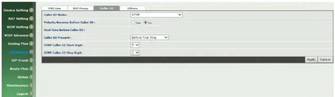
Figure 7-3 Caller ID setting
- Caller ID Mode: Caller ID mode to be used for phone (FSK Bellcore/FSK ETSI/DTMF)
- Polarity Reverse before caller ID: start polarity reverse before send the caller ID
- Dual tone before caller ID: Send dual tone before caller ID (for FSK ETSI use only)
- Caller ID present: The timing to send the caller ID (Before first ring/after first ring/after first short ring)
- DTMF caller ID start digit: specify the DTMF caller ID start digit (default is D, the range is A to D and #)
- DTMF caller ID stop digit: specify the DTMF caller ID start digit (default is C, the range is A to D and #)
7-4 Others
Flash time and current drop generation time
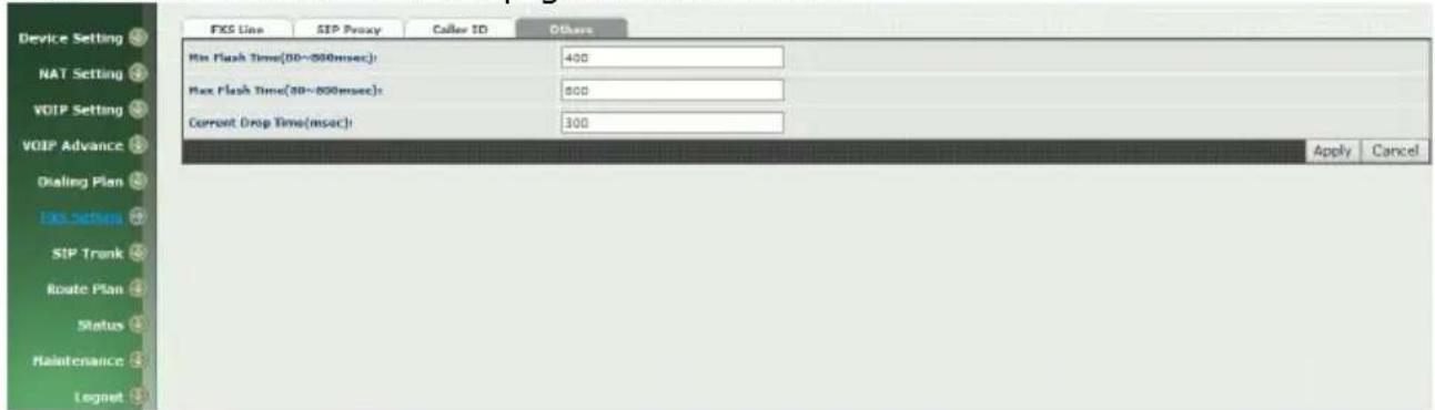
Figure 7-4 Others setting
- Min flash time(80\~800msec): Specify the value of the flash (low), If the phone-set's flash time is smaller than the Flash Low setting, the flash will be ignored.
- MAX flash time (80\~800msec): Specify the value of the flash (high), if the phone-set's flash time is larger than the Flash high setting, the flash will be handled as hang-up.
- Current Drop Times (msec): Specify the value of the current drop times (generate – for FXS / detect – for FXO).
CH8 SIP Trunk
The administrator needs to set the SIP trunk for VOIP outgoing call and incoming call. There are up to 4 SIP trunk can be used for whole system.
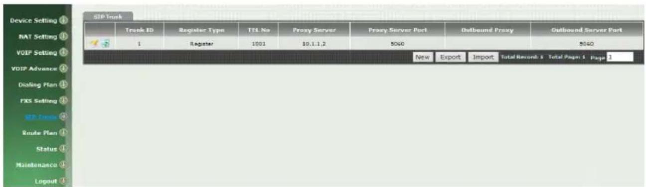
Figure 8-0 SIP Trunk setting
- Trunk ID: SIP trunk ID 1 to 4
- Register Type: Register type is predefine or register
- TEL No: The Tel no for the SIP account
- Proxy Server: The SIP proxy server
- Proxy Server port: The SIP proxy server port
- Outbound Proxy: The SIP outbound proxy sever
- Outbound Server Port: The SIP outbound proxy server port
- Export: To backup the SIP Trunk records.
- Import: To reload setting of SIP Trunk.
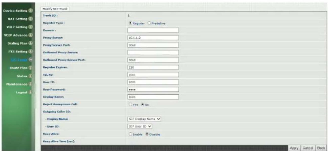
Figure 8-1 SIP Trunk page
- Trunk ID: SIP trunk ID 1-4
- Register Type: Whether this account need register or not
◆ Register: When it is set to register, Wellgate 2504 will send REGISTER message to SIP proxy server for registration.
◆ Predefine: When it is set to predefine, Wellgate 2504 will NOT send REGISTER message out.
- Domain: The SIP domain for register or call making
- Proxy Server: SIP registrar server address
- Proxy Server Port: SIP registrar server port number
- Outbound Proxy Server: outbound proxy server address
- Outbound Proxy server port: outbound proxy server port number
- Register Expires: the default register expires for negotiation
- TEL No: The registrar telephone number
- User ID: The SIP user ID for register and call making
- User Password: The SIP password for register and call making
- Display Name: The SIP display name
- Reject Anonymous Call: Reject the anonymous call
- Outgoing Caller ID: The outgoing SIP caller ID mode.
◆ Display Name: The display name will be set according to the following type.
◆ None: No display name will be used
◆ SIP display name: The display name will be the Display Name
WELLTECH
set in this SIP trunk.
◆ SIP user ID: If the SIP user ID is set, the SIP user ID set in this SIP trunk will be used and the domain/SIP proxy will be the host part. The SIP FROM header's URL will be the SIP_User_ID@Domain or SIP_User_ID@SIP_Proxy_Server.
- Keep Alive: Enable or Disable it.
- Keep Alive Time (sec): Specify of times send sip register message to proxy server.
- Proxy Network Type: the sip server IP is IPv4 or IPv6.
Note: please don't delete sip trunk, even it is not be used, because it have to be used with Route plan.
CH9 Route Plan
The core of Wellgate 2504 is the routing policy. The policy is based on incoming call type/target, length and prefix to determinate the outgoing call process. For VOIP incoming call, it can send to FXS interface and vice versa.
For FXS interface, it could be routed to VOIP and vice versa. You can ignore the routing plan if you don't need it for FXS interface.
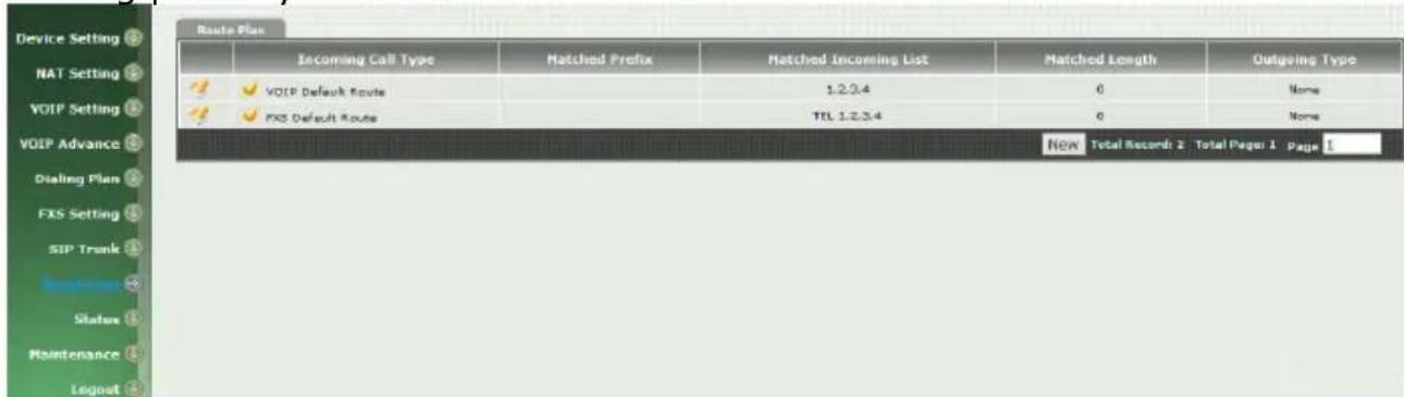
Figure 9-0 Route Plan page
- Incoming Call Type: Incoming call type (VOIP or FXS)
- Matched Prefix: matched DNIS (called number) prefix
- Matched Incoming List: matched DNIS incoming interface target
- Matched Length: matched DNIS (called number) length
- Outgoing Type: The outgoing call type (FXS or VOIP)
9-1 Create Route Plan
Click Route Plan and Click new to create a new routing policy.
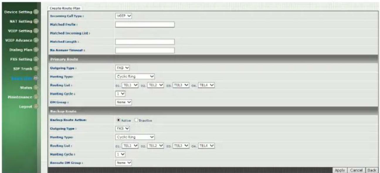
Figure 9-1 Route Plan setting
- Incoming Call Type: Incoming call type
• VOIP: The incoming SIP call type
● FXS: The FXS extensions incoming call type
- Matched Prefix: matched DNIS (called number) prefix
- Matched Incoming List: matched DNIS incoming interface target
- For FXS incoming call type, the incoming target will be the line ID (T1 to T24). Only the call is coming from the selected line will be accepted for this route.
- Matched Length: matched DNIS (called number) length. For ignoring the length, please set to 0.
- No Answer Timeout: How long the hunting will continue to next when the called target doesn't answer.
Create Route Plan>Primary Route
- Outgoing Type: Outgoing call type (FXS or VOIP)
● Hunting Type: The hunting method will be used for this route.
- Priority Ring: The call will be hunted based on the routing list order one by one.
● Cyclic Ring: The call will be hunted based on the cyclic
basis. This is the recommended method.
- Routing List:
● The routing target list will be used for this route.
- DM Group: Select DM group 1 to 4 in case it requires a DM (for example remove the prefix) before to make the call.
Create Route Plan>Backup Route
- Backup Route Active: Active the backup route or not.
- Outgoing Type: The backup route outgoing call type.
● Hunting Type: The hunting method will be used for this route. Please refer to the Primary Route.
- Routing List: The backup routing target list will be used for this route.
- Route DM Group: Select DM group 1 to 4 in case the backup required the DM before to make the call. The DNIS is unchanged by the primary route DM and same as the DNIS before routing. For example, the DNIS is 886282265699 and primary DM group remove 886 and use it (DNIS = 282265699) to make call. When backup route is started, the DNIS is still unchanged as 886282265699. This makes the DM easy to predict and implement.
2 special default route, "VOIP Default Route" and "FXS default Route", are used as the default routing when there is no any other routing are matched. It is not recommended to disable these 2 default route. The FXS default route is used when a FXS outgoing call's default routing. VOIP default route is used for a VOIP incoming call's default routing.
Wellgate 2504 provides the system status here.
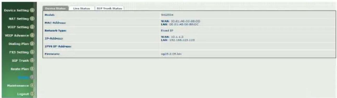
Figure 10-0 Status page
10-1 Device Status
See the figure 10-0 Status page
● Model: The model number
- MAC-Address: The MAC address of Wellgate 2504
● Network Type: The Network Interface Type Settings
- IP-Address: IP address is using
- IPV6 IP-address: display IPV6 address
● Firmware: The firmware version and release information
10-2 Line Status
This page shows the each line's current status.
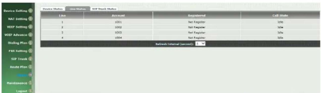
Figure 10-2 Line Status
- Line: L1 to L4
- Account: display each line number
- Registered: display each line register status.
- Call State: The line status for this line
- Refresh Interval (second): The time to refresh the status
10-3 SIP Trunk Status
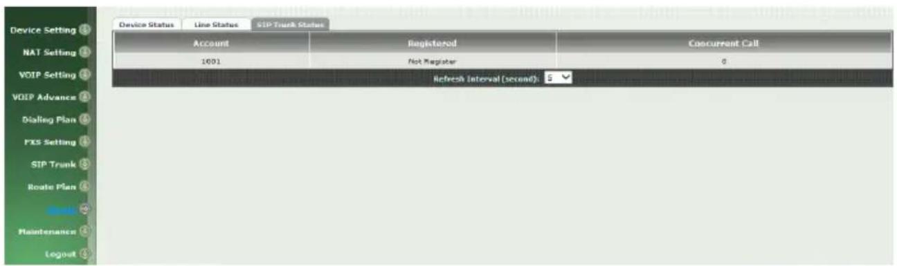
Figure 10-3 SIP Trunk Status
- Account: SIP trunk account
- Registered: The SIP trunk register status
- Concurrent Call: The concurrent calls are used for this SIP trunk
- Refresh Interval (second): The time to refresh the status
CH11 Maintenance
Wellgate 2504 can be managed by this management page for upgrading firmware or reset.
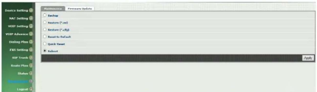
Figure 11-0 Maintenance
- Backup: Backup the system settings for restoring purpose
- Restore (*.ini): Restoring the backup setting back to Welltech 2504
- Restore (*.cfg): Restoring the automatic provisioning file back to Welltech 2504
- Reset to Default: Reset system setting to factory default
- Quick-Reset: Warm Reset without reboot Welltech 2504
● Reboot: reboot Welltech 2504
11-1 Firmware Update
This maintenance page provides the firmware upgrade features.
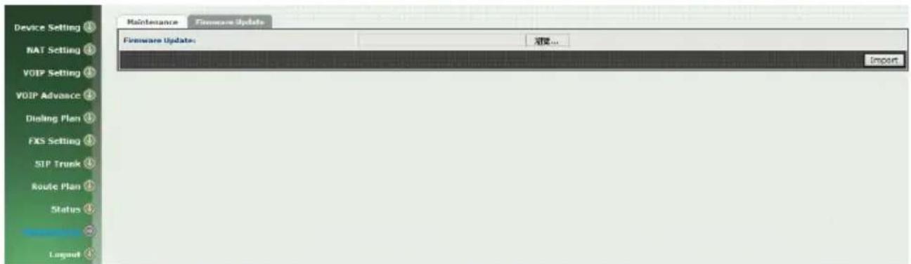
Figure 11-1 firmware update
● Firmware Update: Upgrade the new firmware through web page
CH12 Logout
Click the Logout item to logout web page.
Appendix A--- System Recovery
Wellgate 2504 use dual firmware image to ensure the system stabilities. In most of case, you will not encounter the system failed to boot issue. Normally, the user should able to use Web page to login and upgrade the firmware through it. If you are not able to do it, please following the following steps for recovery.
-
Start the WG2504 and to check the STATUS led is up or not. If STATUS led is ON, please press the reset button for 5 seconds to reset to default. After all LED are light up, the system is back to factory settings.
-
Change your PC IP address to 192.168.123.111 and network set to fix IP address mode.
-
Connect your PC to LAN port and use http://192.168.123.123 to upgrade the firmware. Make sure you are using Microsoft IE 6 or later version. Do not support Firefox Web browser.
-
If you cannot login to the web page through 192.168.123.123. Open a command line windows and type "telnet 192.168.123.123". If you can see the following display, go to the next step. Otherwise, please contact Welltech FAE for RMA (Repair).
-
Prepare a TFTP server for firmware download as follows
- download tftp server http://www.welltech.com/support/voip/TFTP/TFTP_Server.zip or http://tftpd32.jounin.net/tftpd32_download.html
- start tftp server
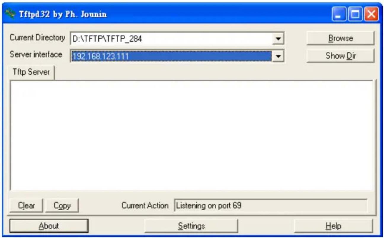
- download the firmware into tftp data directory 6. In the telnet terminal, do the following command
-
- _dmctw
-
- cd /config_fs
-
- rm -f wg25*.bin
-
tftp -g -r wg25.1.0.bin 192.168.123.111
![Tftpd32 by Ph. Jounin Current Directory D:\TFTP\TFTP_284 Server interface 192.168.123.111 Tftp Server Read request for file . Mode octet [12/06 16:03:24.500] Using local port 3882 [12/06 16:03:24.515] wg25.1.0.bin to 192.168.123.123 File size : 1836617 1014272 Bytes sent 48298 Bytes/sec Clear Copy Current Action sing local port 3882 About Settings Help](/content/2026/05/1060707/images/dde03e14ea73e2d700d7ffc9ff3142e1163f701a4987e76b3a8abd6ab365169d.jpg)
-
- copy firmware successfully
-
- reboot
-
Check whether the system was recovered or not
Appendix B --- HTTP auto provisioning
Get the http provisioning packet from Welltech and start the provisioning as follows:
Step 1: build mac list for mass configuration file generation
Please open the "wg2504 MAC.csv gotten from Welltecg by using Microsoft Excel. You can refer the picture below. Normally, you should get all required configuration mac list from Welltech and use it for configuration file generation.
For FXS>
| A | B | C | D | E | F | G | H | I | J | K | L | |
| 1 | $MACAddress | fss1.displayname | fss1.password | fss1.relno | fss1,Aserid | fss2.displayname | fss2.password | fss2.relno | fss2,Aserid | fss3.displayname | fss3.password | fss3.relno |
| 2 | 00Cha8064b31 | 1001 | 1001 | 1001 | 1001 | 1002 | 1002 | 1002 | 1002 | 1003 | 1003 | 1003 |
| 3 | 00Cha8064b32 | 2001 | 2001 | 2001 | 2001 | 2002 | 2002 | 2002 | 2002 | 2003 | 2003 | 2003 |
| 4 | 00Cha8064b33 | 3001 | 3001 | 3001 | 3001 | 3002 | 3002 | 3002 | 3002 | 3003 | 3003 | 3003 |
The wg2504 MAC.csv contains most frequently changed parameters as following:
MACAddress: Wellgate 2504 MAC Address
fxs1.displayname \~ fxs4.displayname: display name for each line fxs1.password \~ fxs4.password: user password for register to SIP proxy for each line
fxs1.telno \~ fxs4.telno: tel no for each line
fxs1.userid \~ fxs4.userid: user id for register to SIP proxy for each line
Please save and close it.
Step 2: create a template configuration file
Open the "wg2504 Parameter.txt" getting from Welltech and make the required change. Please at least make the changes for those provisioning and SIP proxy settings. For detail, please refer the comments of "wg2504 Parameter.txt".
Step 3: Make the change for wegencfg.ini as follows if necessary
# Template File
BaseFile=. \wg2504 Parameter.txt
# MAC list file
ListFile=. \wg2504 MAC.csv
# 0: Off, 1: On
Encrypt=0
Step 4: Generate the individual configuration file.
Double click the "wtgencfg.exe", it will generate the configuration file for each MAC list in "MAC address.cfg" as the following pictures.
![20:54:05 L0114 Notice : wtgencfg.exe 1.0.0 (R091006) start. 20:54:05 L0270 Info : Read ".\wtgencfg.ini". 20:54:05 L0271 Info : [System]. 20:54:05 L0289 Info : Action=0. 20:54:05 L0304 Info : ToCase=0. 20:54:05 L0315 Info : BaseFile=. \wg2504 Parameter.txt. 20:54:05 L0327 Info : ListFile=. \wg2504 MAC.csv. 20:54:05 L0340 Info : HeadTagPrefix=FmtNo=_wtcfg_. 20:54:05 L0348 Info : HeadTagSuffix=wg25xx. 20:54:05 L0355 Info : Encrypt=0. 20:54:05 L0364 Info : Default EncryptKey=***** 20:54:05 L0397 Info : Read ".\wg2504 Parameter.txt" 11800 element(s). 20:54:05 L0454 Info : Read ".\wg2504 MAC.csv" 511 element(s). 20:54:05 L0632 Info : Removed ".\002fa8064b31.cfg". 20:54:05 L0665 Info : Opened ".\002fa8064b31.cfg". 20:54:05 L0703 Info : ".\002fa8064b31.cfg" finished 251 record(s). 20:54:05 L0563 Info : 20:54:05 L0665 Info : Opened ".\002fa8064b32.cfg". 20:54:05 L0703 Info : ".\002fa8064b32.cfg" finished 251 record(s). 20:54:05 L0563 Info : 20:54:05 L0665 Info : Opened ".\002fa8064b33.cfg". 20:54:05 L0703 Info : ".\002fa8064b33.cfg" finished 251 record(s). 20:54:05 L0563 Info : 20:54:05 L0154 Notice : Total 3 file(s) generated. 請按任意鍵繼續...](/content/2026/05/1060707/images/ce2e2aeb6cfd5c77892bdb2c884725a053eab01b2e8d365127b9131e24006f75.jpg)
Step 5:
Put the "*.cfg" file into http or ftp directory. Set the provisioning settings in Wellgate 2504 and reboot to test it. You can use the hfs for http file server. It can be download from http://www.rejetto.com/hfs/.
Note: please link it to download provision file. More information please refers "wg2504 Parameter.txt".
http://www.welltech.com/support/voip2/SIP%20series/FXSO%20series/25x/x/provision/2504/2504_Provision.zip
in peer to peer mode with hotline by port to port application.
Purpose
This paper is going to describe how to configure FXO to FXS in peer to peer mode with hotline function to link from one desire port at FXO via SIP IP link to remote FXS desire port. This application is widely used to extend traditional PABX extension from one location to remote office via IP Link which could be VPN, Private network, fiber link or Wireless network. Here is an typical diagram of this application at Figure 1.
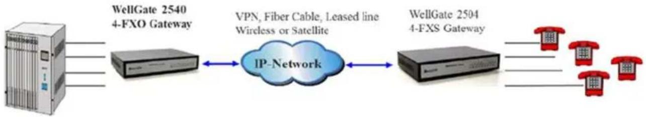
flowchart
graph LR
    A["Server"] --> B["IP-Network"]
    B <--> C["WellGate 2540 4-FXO Gateway"]
    B <--> D["WellGate 2504 4-FXS Gateway"]
    C --> E["VoIPs"]
    D --> F["VoIPs"]
| PABX extension number or PSTN number | FXO Telephone number | FXO SIP trunk ID and number | FXS SIP trunk ID and number | FXS line number | FXS phone caller ID number when FXO select FXO display number | FXS phone caller ID number when FXO enable caller ID detection | |
| Line 1 | 201 | 1001 | 2001 | 1005 | 501 | 1001 | 201 |
| Line 2 | 202 | 1002 | 502 | 1002 | 202 | ||
| Line 3 | 203 | 1003 | 503 | 1003 | 203 | ||
| Line 4 | 204 | 1004 | 504 | 1004 | 204 |
Figure 1.
Before start to configure of both FXO and FXS gateway, we have assigned the following parameters to both devices as follows. Please note that both IP addresses at FXO and FXS gateway's WAN port should be able to see each other. Both FXO and FXS gateway CAN NOT install behind Router or Firewall
WellGate 2504 (4-FXS Gateway) information :
IP address : 192.168.18.201
Line number : 501, 502, 503 and 504
SIP Trunk number:1005
WellGate 2540 (4-FXO Gateway) information :
IP address : 192.168.23.23
SIP Trunk number : 2001
FXO Telephone Number : 1001, 1002, 1003 and 1004
PABX Extension number 201, 202, 203 and 204 which were connected to Port #1 to #4 at FXO Gateway.
WellGate 2504 (FXS Gateway) configuration
Step 1: Configure static IP address to WellGate 2504, like below Figure 2. For example: Set static IP address of 192.168.18.201 at WAN port on Device Setting →Network of WellGate 2504 WEB page.
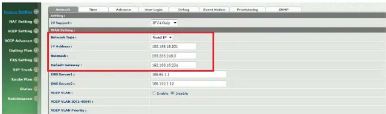
Figure 2.
Step 2: Set the FXS line's information to each port (Line ID is the FXS's port number at Figure 3).
Enable Hotline feature at FXS gateway to port #1 and enter HOT LINE TEL field to 1001 which is WellGate 2540 FXO port 1 number. This command let FXS port #1 point to remote FXO port #1 directly. Continue to configure FXS port number 2 to 4 as following example at Modify Line Setting web page.
See Figure 4.
Enter HOT LINE TEL field to 1002 which is WellGate 2540 FXO port 2 number. (This command let FXS port #2 point to remote FXO port #2 directly.)
WELLTECH
Enter HOT LINE TEL field to 1003 which is WellGate 2540 FXO port 3 number. (This command let FXS port #3 point to remote FXO port #3 directly.) Enter HOT LINE TEL field to 1004 which is WellGate 2540 FXO port 4 number. (This command let FXS port #4 point to remote FXO port #4 directly.)
Step 3: Go to Modify Line Setting webpage (See Figure 4) of FXS gateway at Port #1 (LINE ID 1) to continue setting of port #1. Select Register Type to "Internal". Enter FXS port #1 information as follows. TEL No : 501 User ID : 501 User password: 501 Display Name: 501
Enter FXS port #2 information as follows.
TEL No : 502 User ID : 502 User password: 502 Display Name: 502
Enter FXS port #3 information as follows.
TEL No : 503 User ID : 503 User password: 503 Display Name: 503
Enter FXS port #4 information as follows.
TEL No : 504 User ID : 504 User password: 504 Display Name: 504
Step 4: Select HOT Line to Enable at webpage (See Figure 4) of Line Setting at FXS Gateway. And enter HOT Line TEL at 1001 which is Wellgate 2540 FXO port #1 number.
For example: The FXS port 1 number is 501, FXS port 2 is 502, FXS port 3 is 503, FXS port 4 is 504. FXS port 1 number 501 hotline to FXO SIP Trunk 1 which number is 1001, FXS port 2 number 502 hotline to FXO SIP Trunk 2 which number is 1002, FXS port 3 number 503 hotline to FXO SIP Trunk 3 which number is 1003, FXS port 4 number 504 hotline to FXO SIP Trunk 4 which number is 1004, See Figure 3.

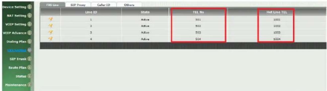
Figure 3.
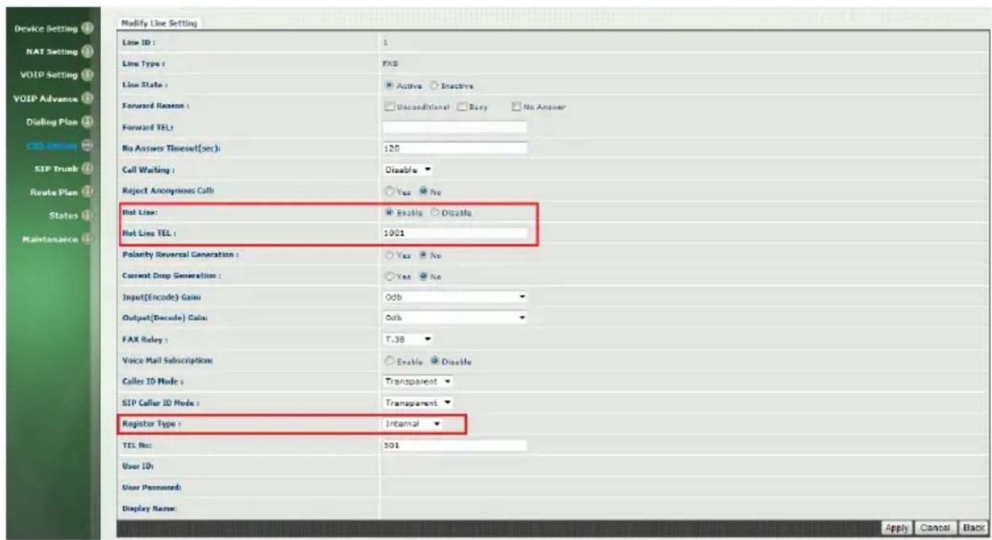
Figure 4.
Step 5: set the SIP Proxy information on FXS Setting →SIP Proxy. See Figure 5.
For example: Set the SIP Proxy Server's IP address at 192.168.23.23, Proxy port number at 8080 and Outbound Proxy server port number at 8080 as well which were FXO's IP address and SIP port number.
Note: You have to fill in remote FXO Gateway's IP address and port number at this step. See figure 5.

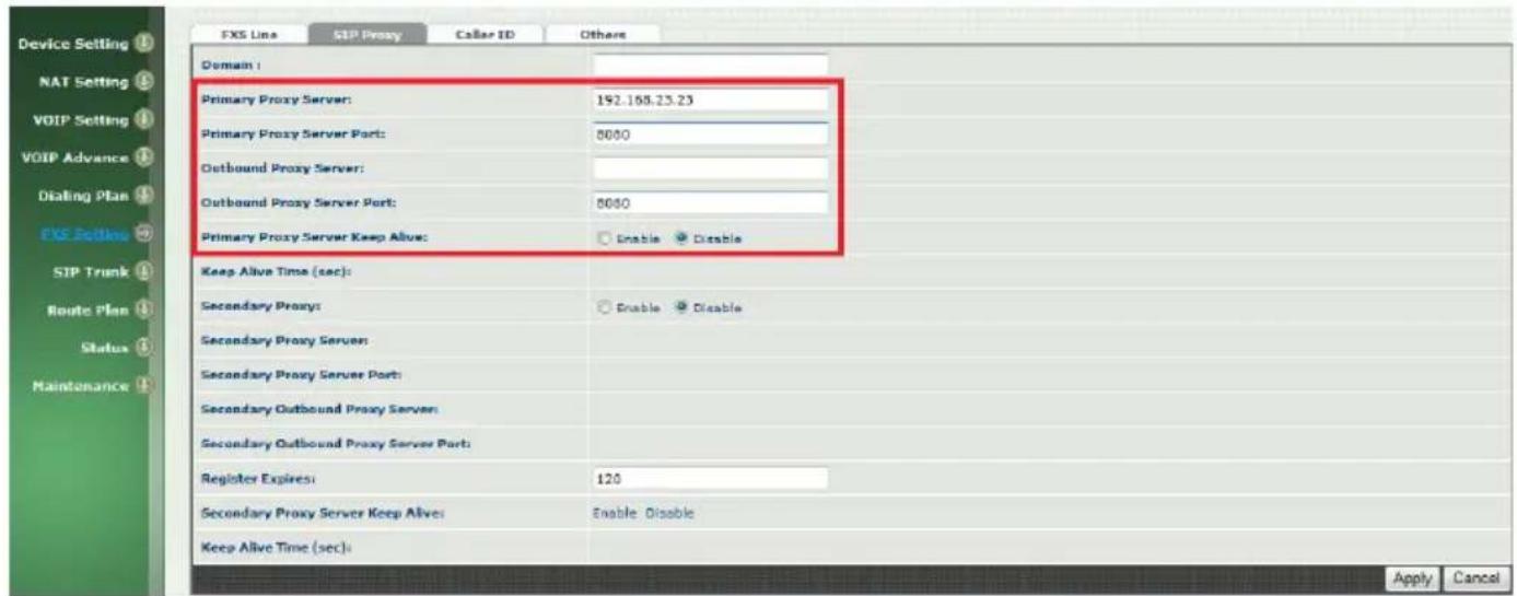
Figure 5.
Step 6: set the SIP Trunk information on SIP Trunk. See Figure 6.
For example: Set the SIP Proxy Server's IP address at 192.168.23.23, Proxy port number at 8080 and Outbound Proxy server port number at 8080 as well which were FXO's IP address and SIP port number.
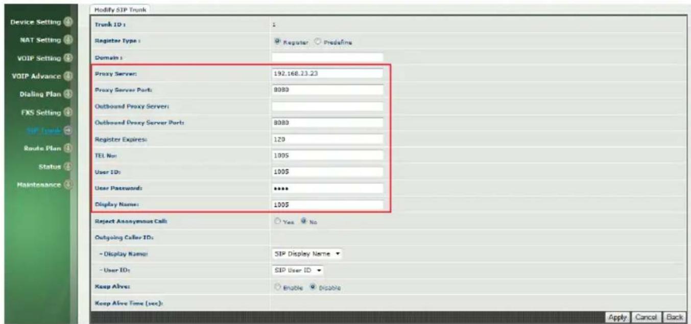
Figure 6.
WellGate 2540 (FXO Gateway) configuration
Step 1: set static IP address to WellGate 2540 FXO gateway's WAN port as following picture. See Figure 8. For example: Set static IP address 192.168.23.23 on Device Setting →Network of WellGate 2540 WEB page.
See Figure 7
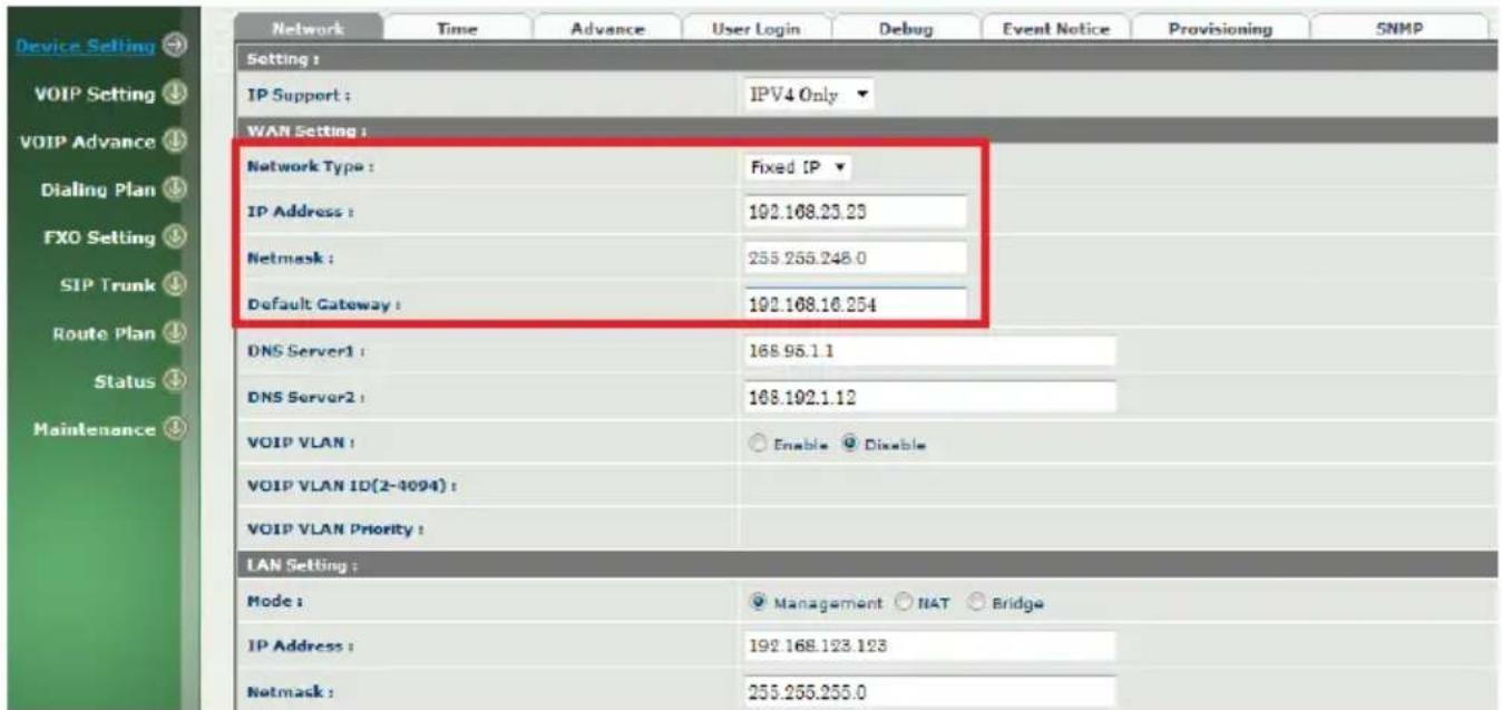
Figure 7.
Step 2: Set the FXO SIP line's information to each line.
Go to FXO Setting webpage of WellGate 2540 FXO Gateway and configure each line by selecting Line ID from 1 to 4. See Figure 8 and Figure 9. Enable Hotline feature by selecting Incoming Call Handling to Hot Line and give remote WellGate 2504 FXS gateway port 1 number to 501. Enter the numbers of TEL No 1001 to 1004 from port 1 to port 4.
For example:
FXO SIP port 1 number 1001 hotline to remote FXS port 1 number 501 directly.
FXO SIP port 2 number 1002 hotline to remote FXS port 2 number 502 directly.
FXO SIP port 3 number 1003 hotline to remote FXS port 3 number 503 directly.
FXO SIP port 4 number 1004 hotline to remote FXS port 4 number 504 directly.
Figure 8.
Figure 9.
Step 4: Set the SIP Trunk information to WellGate 2540 by going to SIP Trunk → Modify SIP Trunk webpage. See Figure 10.
-
Select Register Type to register and key in the Proxy Server IP address at 192.168.18.201 and port 8080 which are remote FXS Gateway's IP address and SIP port number.
-
Next, configure each SIP Trunk number, user ID, password and display name to four SIP Trunks as following examples. See Figure 11.
Enter SIP Trunk #1 information as follows.
TEL No : 2001
- Select "2 Stage Dialing" at "DNIS is Register TEL" webpage. When user picks up the handset from FXS port #1 of WellGate 2504, you should hear Dial Tone from PABX extension 201 which was connected to FXO Line #1. And it works like this analog phone was connected at remote PABX's extension 201. See Figure 10.
If set "1 stage dialing" in here, FXO will dial out line number 1001 to PABX automatically when user picks up the handset from FXS port #1 of WellGate 2504.
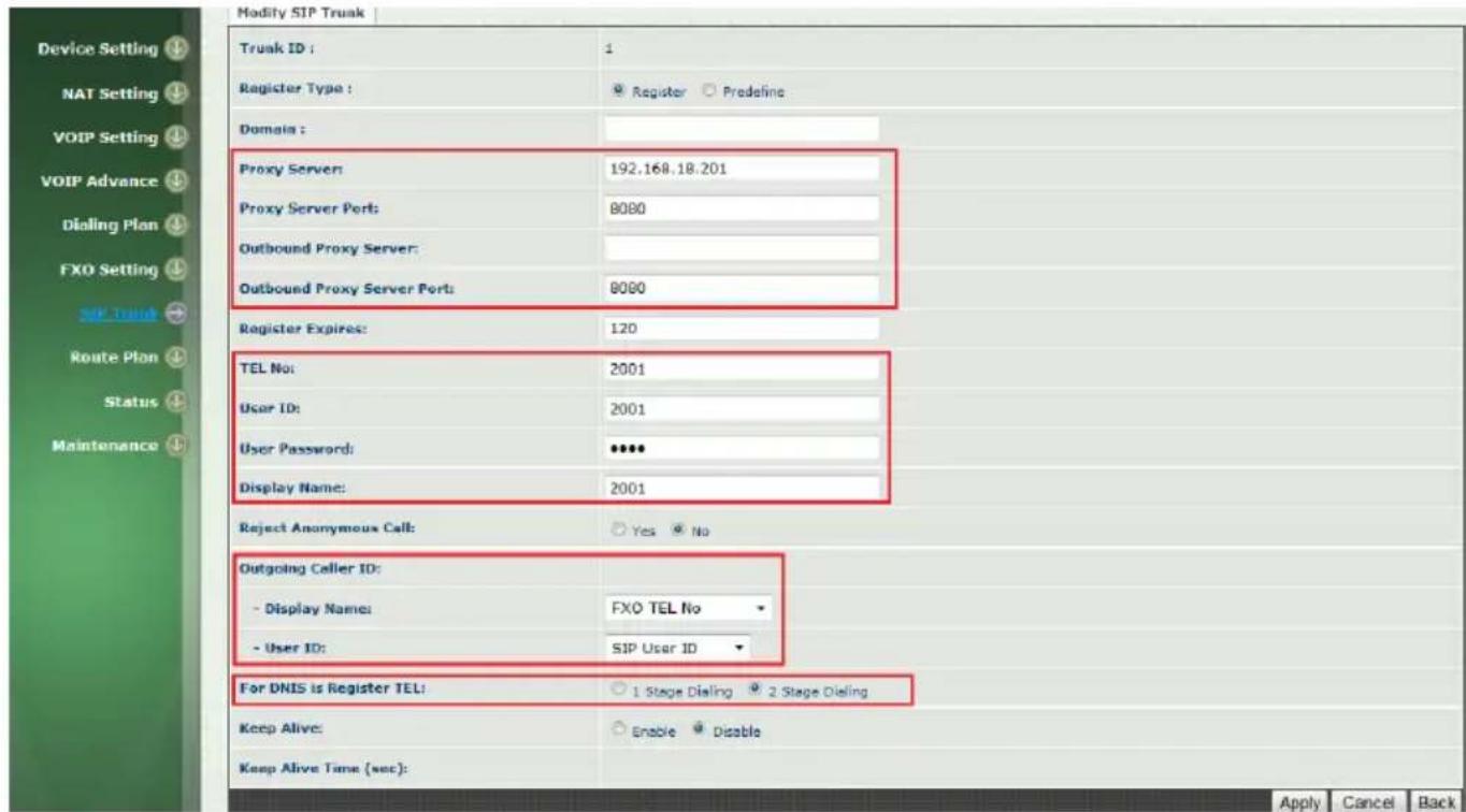
Figure 10.

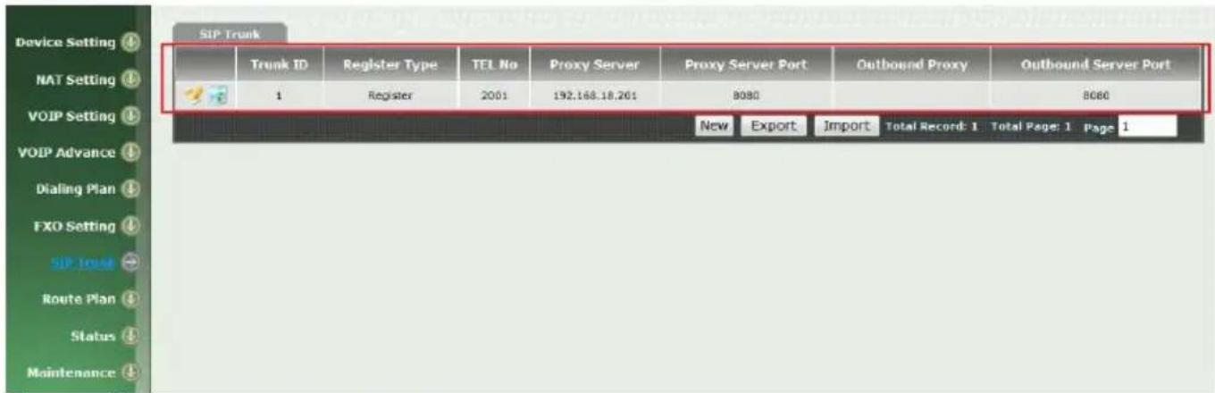
Figure 11.
Configure incoming Ring Cadence to FXO Gateway
When you connect WellGate 2540 FXO gateway Lines to local PABX's extension or PSTN switch, please go to WellGate 2540 webpage setting at VOIP Advance → Ring to configure proper Ring Cadence (Ring ON time and Ring OFF time) according to the PABX or PSTN ring Cadence specification.
Without configuring Ring Cadence to FXO gateway properly according to PABX or PSTN Ring Cadence, FXO may detect Ring signal in a strange behavior and cause abnormal operation.
WellGate 2540 factory default Ring Cadence setting is 1 seconds ON, 2 seconds OFF. Some PABX or PSTN provides 1 second ON and 3 seconds OFF Ring Cadence. In this case, please configure WellGate 2540 Ring Cadence to 1 second ON and 3 seconds OFF to match incoming Ring signal. See Figure 12.
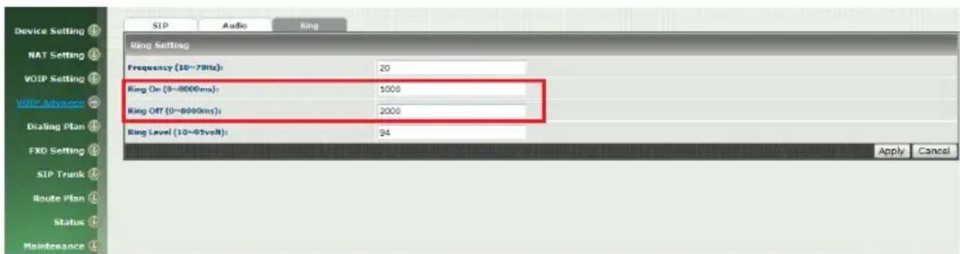
Figure 12.
Enable Caller ID function at FXO and FXS gateway.
The Caller ID configuration at FXO gateway should be configured to match
WELLTECH
PABX extension or local PSTN Caller ID incoming signal in order to carry this signal to remote FXS gateway to display at FXS analog phone set. Of course, the remote FXS Gateway also has to enable Caller ID generation function (see Figure 18.) Here are steps to enable FXO Caller ID detection specification and enable FXS gateway Caller ID generation steps.
Step 1: Make sure the Caller ID mode you have configured to Wellgate 2540 FXO gateway is the same as PABX extension or local PSTN switch which WellGate 2540 FXO Line ports have connected. If you don't know what Caller ID mode you need to configure at FXO gateway, please consult to PABX suppliers or PSTN local switch technician to support you. In global market, there are several Caller ID modes which are most used such as Bellcore FSK, ETSI FSK, ETSI DTMF, Danish DTMF, India DTMF, Brazilian DTMF. See Figure 13.
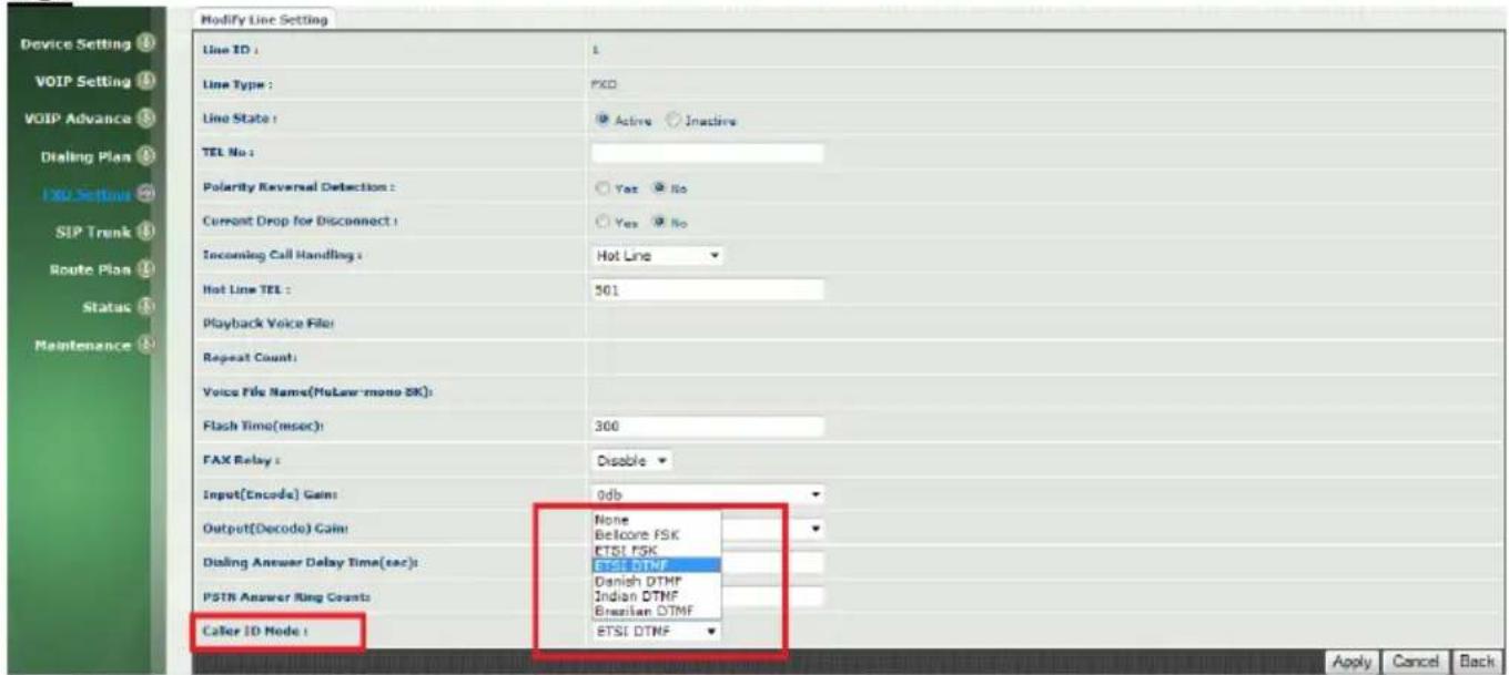
See Figure 13.
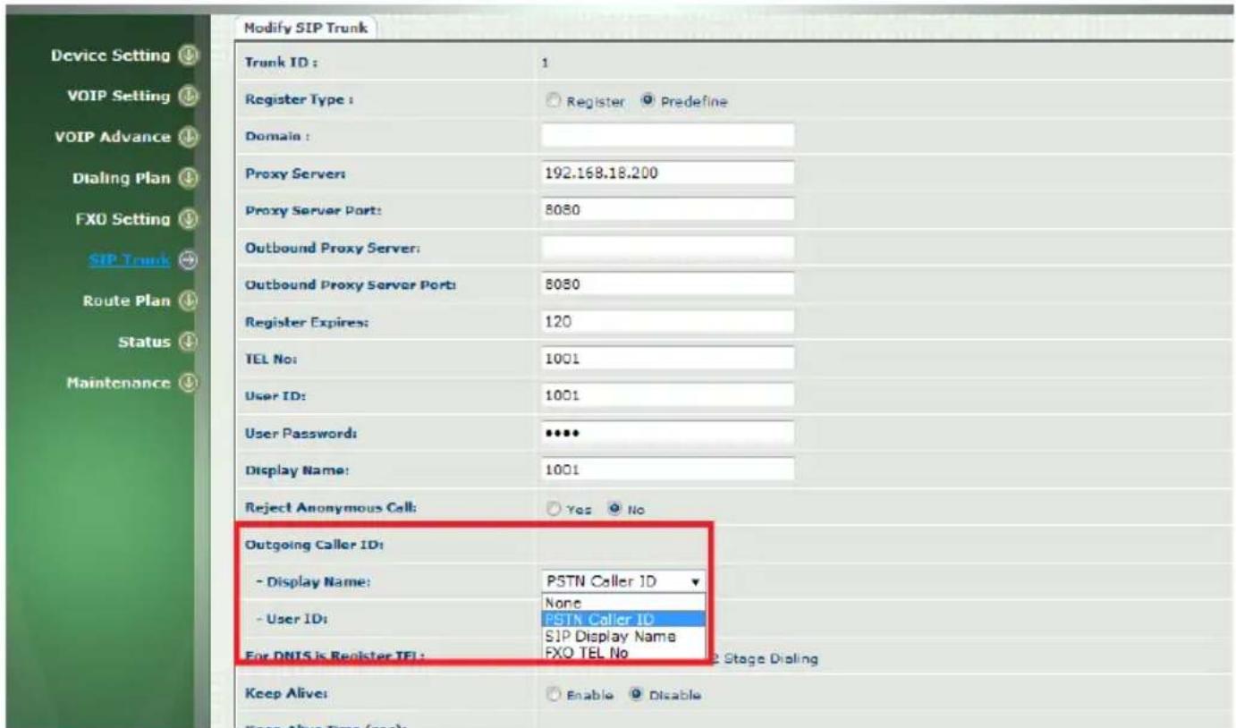
Step 2: Go to FXO Gateway webpage configuration at SIP Trunk → Modify SIP Trunk to enable Outgoing Caller ID with both Display Name: PSTN Caller ID and User ID: PSTN Caller ID as following Figure 14. After this configuration, FXO gateway send detected Caller ID signal from PABX or PSTN Lines to remote FXS gateway. There are additional two options at Display Name and User ID to select what number are going to send to remote FXS gateway. Here are summary of three options.
a. PSTN Caller ID : Deliver Line number from PSTN or PABX extension. At this example, they are number from 201 to 205. See Figure 1. And FXO Caller ID function should be able to detect Caller ID signal correctly.
b. SIP Display Name : See Figure 10 and Figure 11 of SIP Trunk number.
At this example, they are number is 2001.
c. FXO TEL NO.: See Figure 10 to configure TEL NO from FXO Setting →FXO Line →Modify Line Setting → TEL NO. Here, have four numbers from 1001 to 1004. This option allows you to configure your desire Line number to deliver to remote FXS gateway.
See figure 14. FXO Gateway Caller ID Mode.
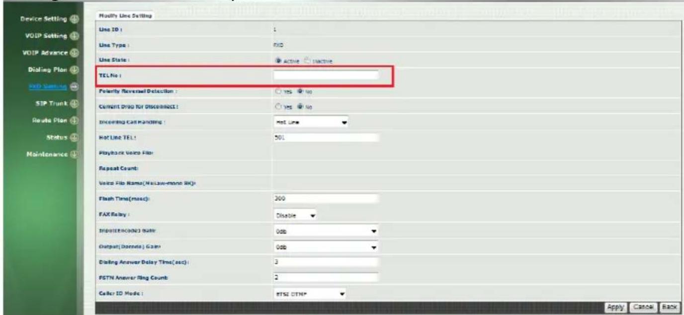
Figure 15. FXO Telephone Number.
Step 3: Enable Caller ID generation at WellGate 2504 FXS gateway. See Figure 16.
Go to FXS Setting → FXS Line → Caller ID Mode to select Transparent to enable Caller ID generation. After enable this command, analog telephone set is able to display Caller ID either FXS phone number (at this example, they are 501 to 504) or display number which were sent from FXO gateway (PSTN, SIP Trunk or FXO Line number).
Step 4: Select FXS gateway's Caller ID Mode. See Figure 17 and 18. FXS Gateway Caller ID generation is able to configure which Caller ID mode in order to match analog phone set's Caller ID specification. Go to FXS Setting → Caller ID → Caller ID Mode to select one of Caller ID Mode (DTMF, FSK Bellcore, FSK ETSI, See Figure 18). There are other options you may need to pay attention at Polarity Reverse Before Caller ID, Dual Tone Before Caller ID, Caller ID Present, DTMF Caller ID start and stop digit. See Figure 18.
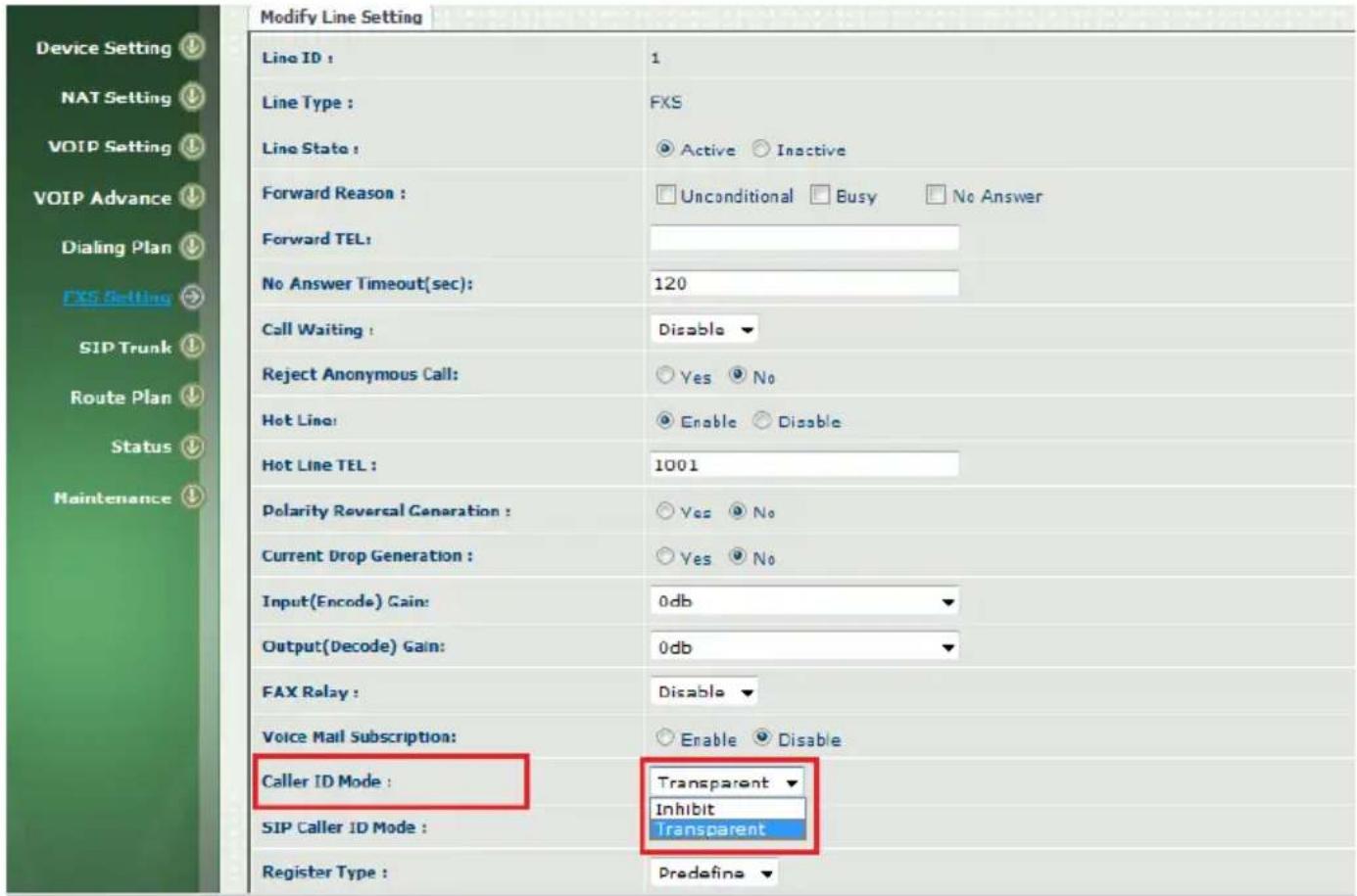
Figure 16. Caller ID feature enable.
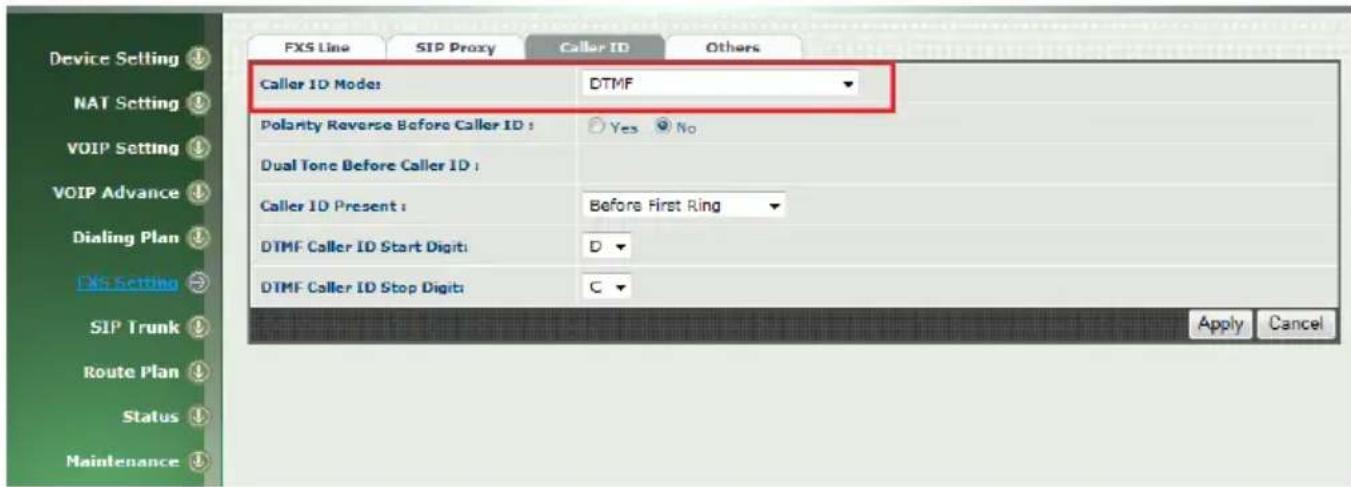
Figure 17. Select Caller ID Mode.
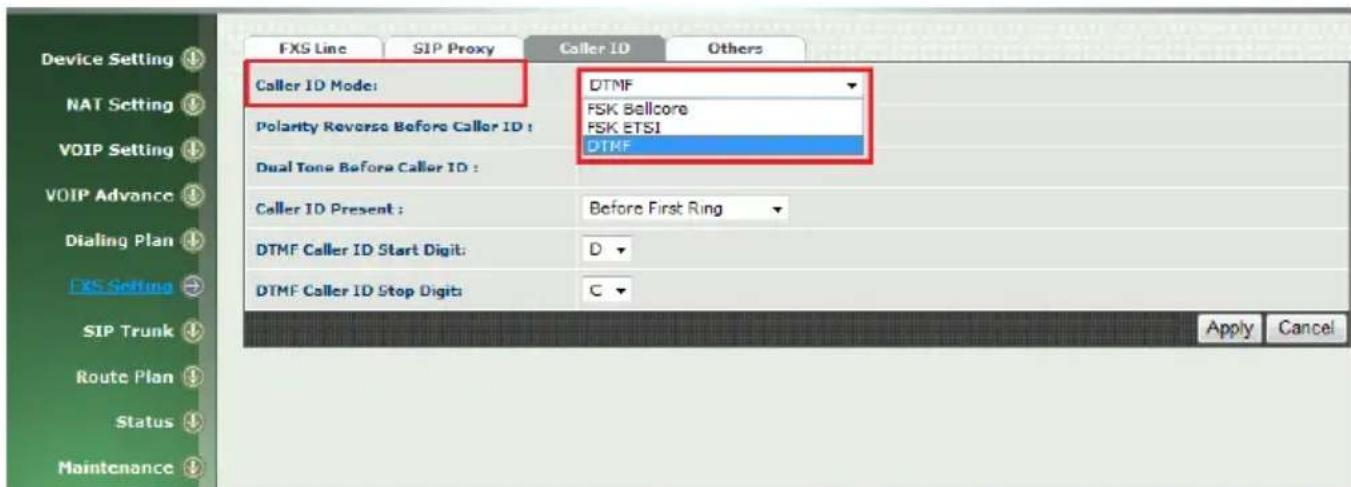
Figure 18. Three options of Caller ID Mode.
Release FXO Line from PSTN or PABX extension after call was dropped.
FXO analog interface detect disconnect tone which was sent from PABX extension or PSTN line to release tip/ring phone wire. In other words, the FXO line can only drop call after detect an effective disconnect tone. In FXO gateway webpage configuration, Go to VOIP Setting → Tone to configure Disconnect 1 and Disconnect 2 in which disconnect tone are needed to match with PABX or PSTN disconnect tone. See figure 19. For details description, please refer to User manual for 2540 firmware ver 2.03f at page 33 in details. You can also go to Country Template to select default setting by each country.

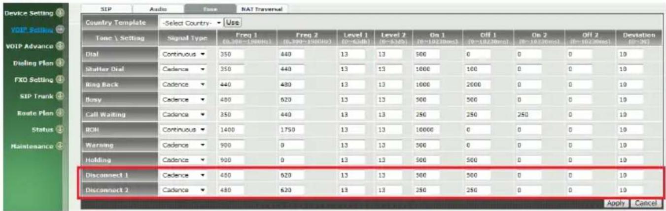
Figure 19. Disconnect tone table.
WellGate 2540 supports an alternative feature to release FXO port by detection Loop Current Drop signal. Go to FXO Setting → Select FXO Line → Modify Line Setting → Current Drop for Disconnect to YES to enable this feature. Once calling user drop this call, PSTN or PABX may drop Loop Current signal for about 300 msec (default setting) to inform FXO interface. To detect Loop current drop duration can be changed. Go to FXS Setting → Others → Current Drop Time. See Figure 21. This feature depends on the PSTN switch or PABX you are using. See Figure 20 at webpage configuration.
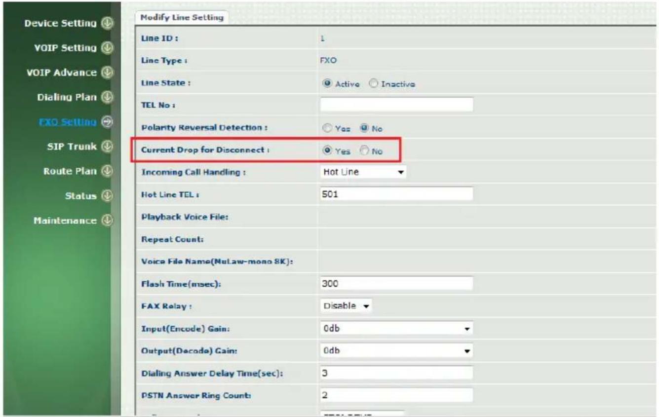
Figure 20. Loop Current Drop to release FXO port
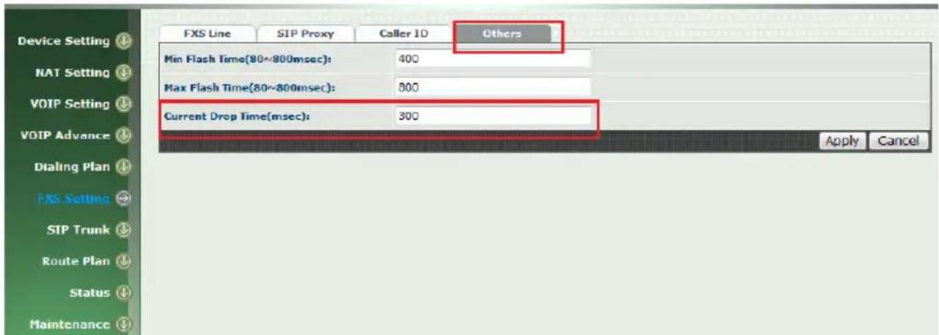
Figure 21. Loop Current Drop detection Time.
MIB value: ".1.3.6.1.4.1.18888.1.2.0"
Command: "[bdb -i keyword -a prefix -v values]", the command include the [ ] two symbol.
[ a ] is add abbreviation ,[ d ] is delete abbreviation, [ i ] is item abbreviation, [ v ] is value abbreviation
For example:[bdb -i Param -a ipa -v 10.1.1.3]
[bdb -i DialPlan -d 911 -v 3]
Parameter list and description.
For Network:
| item | keyword | prefix | Values and description |
| WAN IP | Param | ipa | This IP address(ex:10.1.1.3) |
| WAN submask | Param | ipm | This submask (ex:255.255.255.0) |
| WAN Default Gateway | Param | ipgw | This default gateway(ex:10.1.1.254) |
| DNS 1 | Param | dns1 | DNS server IP |
| DNS 2 | Param | dns2 | DNS server IP |
| NTP Server | Param | ntps | NTP server IP |
| NTP refresh interval | Param | ntpt | NTP refresh interval time(1~65535 sec) |
| Time Zone | Param | tz | -13.5~13.5 (-13:30~+13:30) |
| Http Port | Param | httpp | http port number (default :80) |
| Https Port | Param | httpsp | https port number (default:443)0 is disable. |
| Telnet Port | Param | tldp | Telnet port number (default:23)0 is disable. |
| Administrator Login | Param | u1 | The Administrator login name |
| Administrator Password | Param | u1p | The Administrator password |
| Administrator Language | Prarm | u1langid | 0: English, 1: Traditional Chinese,2: Simple Chinese |
| Supervisor Login | Param | u2 | The supervisor login name |
| Supervisor password | Param | u2p | The supervisor password |
| Supervisor Language | Param | u2langid | 0: English, 1: Traditional Chinese, 2: Simple Chinese |
| User login | Param | u3 | The user login name |
| User password | Param | u3p | The user password |
| User Lagnuage | Param | u3langid | 0: English, 1: Traditional Chinese, 2: Simple Chinese |
| SIP local Port | Param | slpt | This device local port number |
| Rtp port | Param | rtpb | Rtp port number |
Example:
-
To change the "Administrator Password" to test This command is "[bdb -i Param -a u1p -v test]" Notice: if changed password it have to reboot system
-
Read the Administrator Password value This command is "[bdb -i Param -a u1p]"
For Dial Plan:
General
| item | keyword | prefix | Values and description |
| First digit time out | Param | fddt | First digit time out, unit: sec (1-60 sec) |
| Inter digit time out | Param | iddt | Inter digit time out, unit:sec (1-5 sec) |
| End of Digit | Param | eod | 0: none, 1:* , 2:# |
Example:
1.
To change the first digit time out to 30 sec This command is "[bdb -i Param -a fddt -v 30]"
2.
Read the first digit time out value This command is "[bdb -i Param -a fddt]"
Dialing Rule
| item | keyword | prefix | Values and description |
| Dial Rule | DialPlan | N/A | The prefix field must input dialed prefix number.The values field must input this number's total length. (the range is 1~15). |
Example:
1.
If the prefix is 911 total length is 3
This command is "[bdb -i DialPlan -a 911 -v 3]"
2.
If the prefix is 09 total length is 10
This command is "[bdb -i DialPlan -a 09 -v 10]"
3.
Delete prefix 911 on list
This command is "[bdb -i DialPlan -d 911 -v 3]"
4.
Read the DialPlan value
This command is "[bdb -i DialPlan]
Notice: each DialPlan record is using symbol "; " to end.
Digit Manipulation
| item | keyword | prefix | Values and description |
| Digit Manipulation | DigMan | DMGroup,Matched prefix,Matched Length | Start Pos,End Pos,Replace Value |
Each DM Group values.
FXO value is 100
FXS value is 101
VOIP value is 102
DM Group 1 the value is 1 DM Group 2 the value is 2 DM Group 3 the value is 3 DM Group 4 the value is 4
Example:
1.
DM Group is FXS, Matched Prefix is 02, Matched Length is 10, Start Pos is 0, Stop Pos is 0, Replace value is empty.
This command is "[bdb -i DigMan -a 101,02,10 -v 0,0, ]"
2.
DM Group is FXO, Matched Prefix is 822, Matched Length is 0, Start Pos is 0, Stop Pos is 0, Replace value is 02.
This command is "[bdb -i DigMan -a 100,822,0 -v 0,0,02]"
3.
DM Group is 4, Matched Prefix is 886, Matched Length is 0, Start Pos is 0, Stop Pos is 2, Replace value is 009.
This command is "[bdb -i DigMan -a 4,886,0 -v 0,2,009]"
4.
Delete DM Group 4 on list.
This command is "[bdb -i DigMan -d 4,886,0 -v 0,2,009]"
5.
Read DM values
This command is "[bdb -i DigMan]"
Notice: each DM record is using symbol "; " to end.
Phone Book
| item | keyword | prefix | Values and description |
| Phone Book | PhoBook | N/A | The prefix field can input name or number.The values field can input name or number or IP URL. |
Example
1.
Name is WellTech, Tel No is 82265699
This command is "[bdb -i PhoBook -a WellTech -v 82265699]"
2.
Name is 1001, Tel No is 1001@10.1.1.3:5060
This command is "[bdb -i PhoBook -a 1001 -v 1001@10.1.1.3:5060]"
3.
Delete WellTech on list
This command is "[bdb -i PhoBook -a WellTech -v 82265699]"
4.
Read the Phone Book list.
This command is "[bdb -i PhoBook]"
Notice: each Phone Book record is using symbol "; " to end.
FXO Line(CO Line)
| item | keyword | prefix | Values and description |
| FXO Line or CO Line | Line | fxo1Tofxo4According that how many the FXO port. (please refer the Line ID, if line ID is 1,the prefix is fxo1) | Below in accordance with the priority arrangementTEL No,Polarity Reversal Detection, Current Drop for Disconnect, Incoming Call Handling,Hot Line Tel, FAX Relay,Flash Time(sec), Input(Encode)Gain,Output(Decode)Gain,Dialing Answer Delay Time(sec), PSTN Answer Ring Count,Caller ID Mode,Playback Voice File,Repeat Count,Voice File Name,0,0,0,0,0 |
Each option values description
◆ TeL No: FXO Tel No number
◆ Polarity Reversal Detection: 0 is disable, 1 is enable.
◆ Current Drop for Disconnect: 0 is disable, 1 is enable.
◆ Incoming Call Handling: 0 is Hot line, 1 is 2 stage dialing.
◆ Hot Line Tel: this port hot line number.
◆ FAX Relay: 0 is disable, 1 is bypass, 2 is T38
◆ Flash Time(sec): this fxo port flash time
◆ Input(Encode) Gain: the range is from 0(mute) to 37(+5db)
◆ Output(Decode)Gain: the range is from 0(mute) to 37(+5db)
◆ Dialing Answer Delay Time(sec): unit is sec
◆ PSTN Answer Ring Count: PSTN Answer Ring Count
◆ Caller ID Mode: none is -1, Bellcore FSK is 1, ETSI FSK is 2, ETSI DTMF is 3, Danish DTMF is 4, Indian DTMF is 5, Brazilian DTMF is 6.
◆ Playback Voice File: 0 is disable, 1 is enable.
◆ Repeat Count: the repeat count
◆ Voice File Name: the voice file name (default is greeting.pcm)
◆ 0: it is reserved field, please don't change this value.
◆ 0: it is reserved field, please don't change this value.
◆ 0: it is reserved field, please don't change this value.
◆ 0: it is reserved field, please don't change this value.
◆ 0: it is reserved field, please don't change this value.
Example:
1.
Set the fxo tel no to 999 and hotline number to 888.
This command is
999,0,0,0,888,2,500,32,32,3,2,3,1,5,greeting.pcm,0,0,0,0,0]”
If input command is
"[bdb -i Line -a fxo1 -v 999,0,0,0,888]"
The behind values will be changed to 0
Notice: please input completely command line, there should have 19 commas(,).
2.
Read each line values
This command is "[bdb -i Line -a fxo1]"
FXS Line (Tel Line)
| item | keyword | prefix | Values and description |
| FXS LineOrTel Line | Line | fxs1Tofxs4According that how many the FXS port. (please refer the Line ID, if line ID is 5,the prefix is fxs5) | Below in accordance with the priority arrangement0,Forward Reason,Forward Tel,No Answer Timeout(sec),Call Waiting,Reject Anonymous call,600,Hot Line, Hot Line Tel,Polarity Reversal Generation,Current Drop Generation,Input(Encode) Gain, Output(Decode) Gain,Register Type,0,TEL No,User ID,User Password,Display Name,FAX Relay,Voice Mail Subscription,Caller ID Mode,SIP Caller ID Mode,0,0,0 |
Each option values description
◆ 0: it is reserved option, please don't change this value.
◆ 0: it is reserved option, please don't change this value.
◆ Forward Reason: 0 is not selected, 1 is unconditional, 2 is busy, 4 is No Answer, 6 is busy and No Answer.
◆ Forward Tel: the FXS port forward number
◆ No Answer Timeout(sec): this FXS port no answer time (unit: sec)
◆ Call Waiting: 3 is disable, 2 is enable.
◆ Reject Anonymous call: 0 is disable, 1 is enable.
◆ 600: it is reserved option, please don't change this value.
◆ Hot Line: 0 is disable, 1 is enable.
Hot Line Tel: Hotline number
◆ Polarity Reversal Generation: 0 is disable, 1 is enable.
◆ Current Drop Generation: 0 is disable, 1 is enable.
◆ Input(Encode) Gain: the range is from 22(-10db) to 37(+5 db)
◆ Output(Decode) Gain: the range is from 22(-10db) to 37(+5 db)
◆ Register Type: 0 is register, 1 is predefine, 2 is internal.
◆ 0 : it is reserved option, please don't change this value.
- TEL No: this fxs port phone number.
◆ User ID: this fxs port registers account.
◆ User Password: this fxs port authentication password.
WELLTECH
◆ Display Name: this fxs port display name.
◆ FAX Relay: 0 is disable, 1 is bypass, 2 is T38.
◆ Voice Mail Subscription: 0 is disable, 1 is enable.
◆ Caller ID Mode: 0 is inhibit, 1 is Transparent
◆ SIP Caller ID Mode: 0 is inhibit, 1 is Transparent
◆ 0: it is reserved option, please don't change this value.
◆ 0: it is reserved option, please don't change this value.
◆ 0: it is reserved option, please don't change this value.
Example:
1.
Set the tel no/ user id/ user password/ display nema to 101/101/welltech/Eddie and hot line number to **999 for fxs port 5.
This command is
"[bdb -i Line -a fxs5 -v
0,0,,120,3,0,600,1,**999,0,0,32,32,0,0,101,101,welltech,Eddie,2,0,1,1,0,0,0]”
2.
Set the busy and no answer forward to 201 for fxs port 5.
This command is
"[bdb -i Line -a fxs5 -v
0,6,201,120,3,0,600,1,**999,0,0,32,32,0,0,101,101,welltech,Eddie,2,0,1,1,0,0,0]”
Notice: please input completely command line, there should have 25 commas(,) totally. If lost anyone commas, this page will be cleaned to empty or 0 for all values.
3.
Read each line values
This command is "[bdb -i Line -a fxs1]"
SIP Proxy (FXS use only)
| item | keyword | prefix | Values and description |
| SIP Proxy | Line | px | Below in accordance with the priority arrangementDomain, Primary Proxy Server, Primary Proxy Server Port, Outbound Proxy Server, Outbound Proxy Server Port, Secondary Proxy Server, Secondary Proxy Server Port, Secondary Outbound Proxy Server, Secondary Outbound Proxy Server Port, Register Expires, Secondary Proxy, Primary Proxy Server Keep Alive, Keep Alive Time (sec), Secondary Proxy Server Keep Alive, Keep Alive Time (sec), 0 |
Each option values description
◆ Domain: this proxy domain name
◆ Primary Proxy Server: this primary proxy server IP address
◆ Primary Proxy Server Port: this primary proxy server port number
◆ Outbound Proxy Server: this outbound proxy server
◆ Outbound Proxy Server Port: this outbound proxy server port number
◆ Secondary Proxy Server: this secondary proxy server IP address
◆ Secondary Proxy Server Port: this secondary proxy server port number.
◆ Secondary Outbound Proxy Server: this secondary outbound proxy server IP address
◆ Secondary Outbound Proxy Server Port: this secondary outbound proxy server port number.
◆ Register Expires: register expires time
◆ Secondary Proxy: 0 is disable, 1 is enable.
◆ Primary Proxy Server Keep Alive: 0 is disable, 1 is enable.
◆ Keep Alive Time (sec): keep alive time for primary proxy server(the range is 30 to 300 sec)
◆ Secondary Proxy Server Keep Alive: 0 is disable, 1 is enable.
◆ Keep Alive Time (sec): keep alive time for secondary proxy server. (the range is 30 to 300 sec)
◆ 0: it is reserved option, please don't change this value.
Example:
1.
Set the domain name to welltech.com and primary proxy to 192.168.18.247, primary proxy port to 8888, outbound proxy to 192.168.18.247, outbound proxy port to 8888.
This command is
"[bdb -i Line -a px -v
welltech.com,192.168.18.247,8888,192.168.18.247,8888,,0,,0,120,0,0,0,0,0,0]”
Notice: please input completely command line, there should have 15 commas(,).
2.
Read Sip Proxy values
This command is [bdb -i Line -a px]
SIP Trunk
| item | keyword | prefix | Values and description |
| SIP Trunk | SipTrunk | 1~4According the sip trunk ID | Below in accordance with the priority arrangementTrunk ID, Register Type, 0, Domain, Proxy Server, Proxy Server Port, Outbound Proxy Server, Outbound Proxy Server Port, Register Expires, TEL No, User ID, User Password, Display Name, Reject Anonymous Call, Display Name, User ID, For DNIS is Register TEL, Keep Alive, Keep Alive Time (sec), 0 |
Each option values description
◆ Trunk ID: this Trunk ID number from 1 to 4.
◆ Register Type: 0 is register, 1 is predefine
◆ 0: it is reserved option, please don't change this value.
◆ Domain: this proxy domain name
◆ Proxy Server: this proxy server IP address
WELLTECH
◆ Proxy Server Port: this proxy server port number.
◆ Outbound Proxy Server: this outbound proxy server IP address
◆ Outbound Proxy Server Port: this outbound proxy server port number.
◆ Register Expires: the register expires time.
- TEL No: the sip trunk line number.
◆ User ID: this sip trunk register account
◆ User Password: this sip trunk authentication password
◆ Display Name: this sip trunk display name
◆ Reject Anonymous Call: 0 is disable, 1 is enable.
◆ Display Name: 0 is none, 1 is PSTN Caller ID, 2 is SIP User ID, 3 is FXO Tel No.
◆ User ID: 0 is SIP User ID, 1 is PSTN Caller ID, 2 is FXO Tel No
◆ For DNIS is Register TEL: 0 is 1 stage dialing, 1 is 2 stage dialing
◆ Keep Alive: 0 is disable, 1 is enable.
◆ Keep Alive Time (sec): keep alive time (the range is 30 to 300 sec)
◆ 0: it is reserved option, please don't change this value.
Expamle:
1.
Create a sip trunk.
Trunk ID 3, trunk number 0700123456, trunk account test, trunk password test123, trunk display name welltech.
Proxy server domain name welltechtech.com, proxy ip 192.168.18.247, Proxy port 8888, outbound proxy ip 192.168.22.247, outbound proxy port 8890, expire time 60.
This command is
"[bdb -i SipTrunk -a 3 -v
3,0,0,welltechtest.com,192.168.18.247,8888,192.168.22.247,8890,60,070
0123456,test,test123,welltech,1,1,0,1,0,0,0]”
Notice: please input completely command line, there should have 19 commas(,) .
2.
Read the SIP Trunk values
This command is [bdb -i SipTrunk]
Notice: each SIP Trunk record is using symbol "; " to end.
Status
| item | keyword | prefix | Values and description |
| Line Status | line0 ~ line3 | N/A | It can read line type and status. |
| SIP Trunk Status | trunk0 ~ trunk3 | N/A | It can read sip trunk strtus. |
Expamle:
Reading line 1 and sip trunk 1 status
This command is:
[bdb -s line0]
---- to ready line 1 status
[bdb -s trunk0]
---- to ready sip trunk 1 status
Reboot
| item | keyword | prefix | Values and description |
| Reboot | Reboot | N/A | N/A |
This command is "[reboot]"