
VE01-B22L - Intercom ZKTeco - Free user manual and instructions
Find the device manual for free VE01-B22L ZKTeco in PDF.

| Product Type | Intercom |
| Brand | ZKTeco |
| Model | VE01-B22L |
| Dimensions (approx.) | 200 x 80 x 40 mm |
| Weight (approx.) | 0.5 kg |
| Power Supply | 12V DC, 1A |
| Display | 7-inch TFT LCD |
| Camera | 720p HD with night vision |
| Audio | Two-way full-duplex |
| Connection | Wired (RJ45) |
| Functions | Video doorbell, remote unlock, intercom, motion detection |
| Operating Temperature | -10°C to 50°C |
| Maintenance | Clean with a soft dry cloth; avoid liquids |
| Safety | Low voltage; indoor use only |
| Spare Parts | Contact manufacturer or authorized dealer |
| Repairability | Professional servicing recommended |
Frequently Asked Questions - VE01-B22L ZKTeco
User questions about VE01-B22L ZKTeco
0 question about this device. Answer the ones you know or ask your own.
Ask a new question about this device
Download the instructions for your Intercom in PDF format for free! Find your manual VE01-B22L - ZKTeco and take your electronic device back in hand. On this page are published all the documents necessary for the use of your device. VE01-B22L by ZKTeco.
USER MANUAL VE01-B22L ZKTeco
Please follow the user manual for correct installation and testing. If there is any doubt please call our tech-supporting and customer center.
Our company applies ourselves to reformation and innovation of our products. No further notice for any change. The illustration shown here is only for reference. If there is any difference please take the actual product as the standard.
The product and batteries must be handled separately from household waste. When the product reaches the end of service life and needs to be discarded, please contact the local administrative department and put it in the designated collection points in order to avoid the damage to the environment and human health caused by any disposal. We encourage recycling and reusing the material resources.
Index
Remark 2
Application:....1
Product description....1
Product appearance....2
Basic function ....3
Technical parameter....3
Package contents....4
Basic operation....5
WEB settings....6
- Network Settings....6
- Device Settings....7
- Access Settings......8
- Card registration....8
- SIP Settings....9
- Call Forwarding....10
- Advanced Settings....10
-
Other Settings....12
-
Logout....12
System connection diagram....13
Wiring diagram of outdoor panel....14
-
RS485 interface....15
-
Exit Button/Door Magnetic Switch 15
-
Network Interface....16
- Power/Switching value output....16
- RS485/Exit/Door Magnetic....16
- RS485/Switching Value Output/Exit/Door Magnetic 17
- Wiegand interface 18
Installation instructions ....19
Troubleshooting....20
Safety & Precautions....21
Safety & Precautions....21
Prevent electric shock, fire and explosion....21
Clean surface 21
Other matters needing attention....21
Product description
Application:
VE01-B23L is outdoor panel based on TCP/IP communication protocol, supporting digital video intercom and SIP communication protocol.
Operating system: Linux
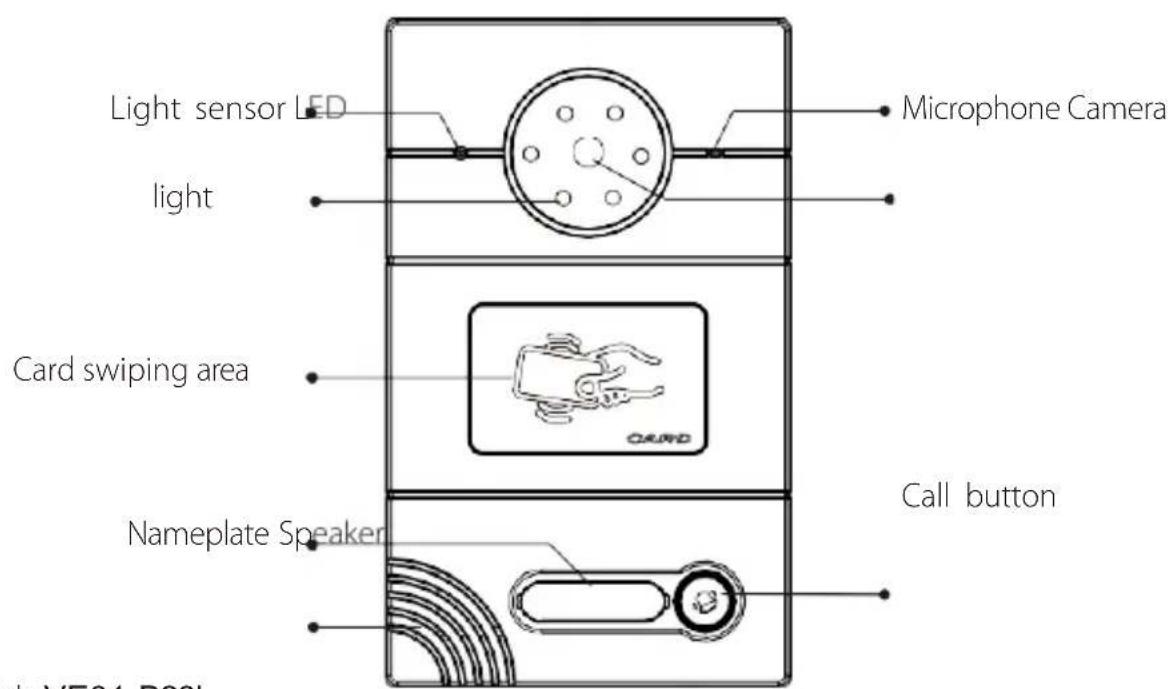
Product appearance
Model: VE01-B22L
Model: VE01-B23L
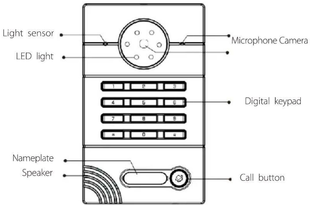
Basic function
◇ Call indoor monitor by one button;
◇ Support unlocking by IC/ID access control card or password(ID Optional); (Note: this function is only applicable to the panel with card swiping function.)
◇ IC/ID card information can be registered on outdoor panel. Registration information of max. 100,000 IC/ID cards can be stored(ID Optional);
(Note: this function is only applicable to the panel with card swiping function.)
◇ Support unlocking by Exit button and door magnetic detection ;
◇ Support LED light for night vision ;
◇ Support POE power supply (optional).
Technical parameter
◇ Working voltage: DC12V
◇ Rated power: 3W
Standby power: 1.5W
◇ Camera resolution: 1280x720
◇ Working temperature: -40\~+70°C
◇ Storage temperature: -10\~+70°C
◇ Storage relative humidity: 20%\~93%
◇ CPU frequency: 1GHz
Package contents
Model : VE01-B23L

Basic operation
1. Call indoor monitor
In standby mode, press the call button on outdoor panel to call indoor monitor. During the call, press the call button on outdoor panel again to end the call. If the call fails or indoor monitor is busy, outdoor panel will emit a beep.
2. Unlocking by card
Put the registered IC/ID (ID Optional) card on card reader area of the outdoor panel. If IC/ID (ID Optional) card has been authorized, after unlocking the door by card, the system will issue a voice message that "the door has been opened", otherwise it will emit a beep. (Note: this function is only applicable to the panel with card swiping function.)
2. Unlocking by access password
In standby mode, enter "unlocking password+#". After unlocking, the system will issue a voice message that "the door has been opened", otherwise it will emit a beep.
WEB settings
Connect outdoor panel to PC through the switch. Input IP address of outdoor panel in the web browser of PC (The IP addresses of PC and outdoor panel must be in the same network segment. Default IP address is 192.168.68.90), then input user name and password (default user name is "admin" and the password is "123456") to enter into the following interface:
| Smart Home And Intercom System | |
| FW: 1.5.4 20170221 UI: 1.0.0 20170405 | |
| SIP: ERR |
1. Network Settings
Click the icon "Network" on the left side to enter the interface as shown below:
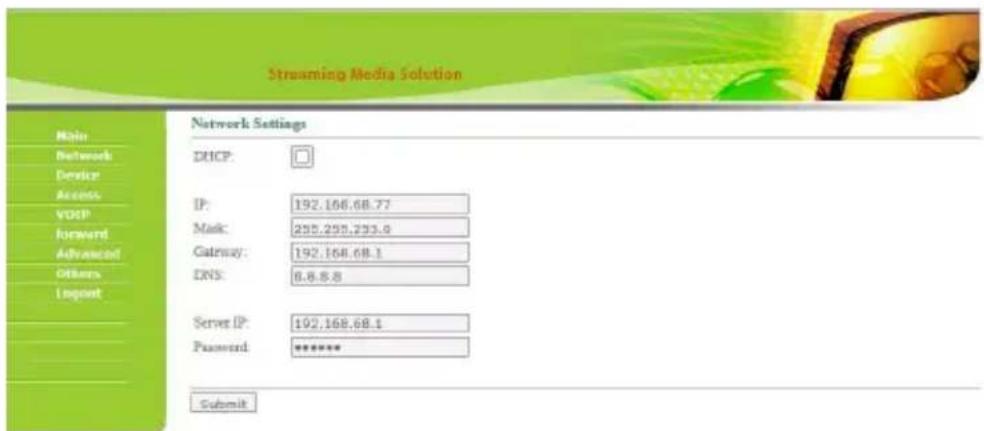
DHCP: dynamic IP function.
IP address: for the same system on the same network segment, IP address can not be repeated.
Subnet mask: the original subnet mask is 255.255.255.0, which normally doesn't need to be changed.
Default gateway: according to the project site IP network allocation
DNS: it refers to IP address of the DNS server
Server IP: IP address of digital management software installed in the management center computer
Access password: IP access password for management software
Normally, management center, indoor monitor and outdoor panel are in the same LAN for communication; if they are not in the same LAN, the call can be realized on the internet; in this case, SIP server needs to be set.
After the setup is completed, click the icon "Submit" to enable the settings.
2. Device Settings
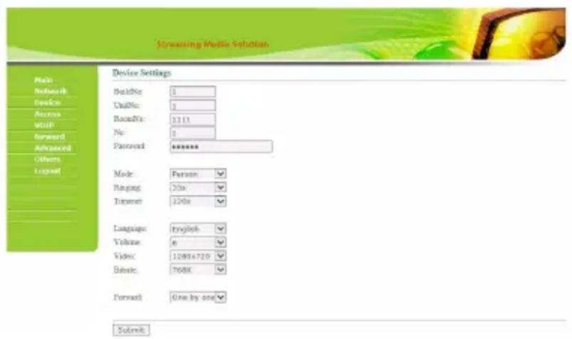
Building No. and Unit No. are the ones where outdoor panel is located.
The No. can be set from 1 to 9. Device No. is mainly used for distinguishing the outdoor panel when it is watched by indoor monitor.
Password refers to the one used in your login to the webpage for outdoor panel settings (default password is 123456).
Outdoor Panel Mode: Person Panel (Villa Outdoor Panel)
Language selection: only support simplified Chinese and English.
System volume: adjust the system volume with 6 levels for selection. Video size:
320x240, 640x480 or 1280x720.
Call forwarding: the call can be made one by one or simultaneously.
After the setup is completed, click the icon "Submit" to enable the settings.
3. Access Settings
Click the icon "Access" on the left side to enter the interface as shown below:
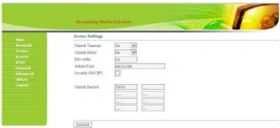
Unlock Timeout is used for controlling the unlocking time ranging from 1 to 9s.
Unlock Delay refers to the delayed time of opening the door ranging from 0 to 9s.
Elev refer is used for setting the floor of outdoor panel ranging from 01\~99. (It is effective when outdoor panel is set as unit panel).
4. Card registration
The Admin Card is used for registering user card. There are two ways of registering the admin card:
- The user enters card No. of the admin card in the box after "Admin Card" and then click the button "Submit". In this case, the admin card is registered successfully.
- If the user isn't aware of admin card No., please enter 0 in the box first and click the button "Submit". Then place the admin card close to the swiping area. When the system gives an indication tone, it means that the admin card is registered successfully.
Then register the user card. The user shall swipe the admin card first. The system emits a beep. Then place the card to be registered near the swiping area within 10 seconds. When the system gives an indication tone, it means that the user card is registered successfully. When registering the user card, the card to be registered shall be swiped 10 seconds after the admin card is swiped. Once a user card is registered, the registration time will postpone for 10 seconds. When there is no activity for 10 seconds, the system will exit from registration status automatically. To register a new user card, the user shall swipe the admin card aagain.
5. SIP Settings
Click the icon "VOIP" on the left side to enter into the following interface:
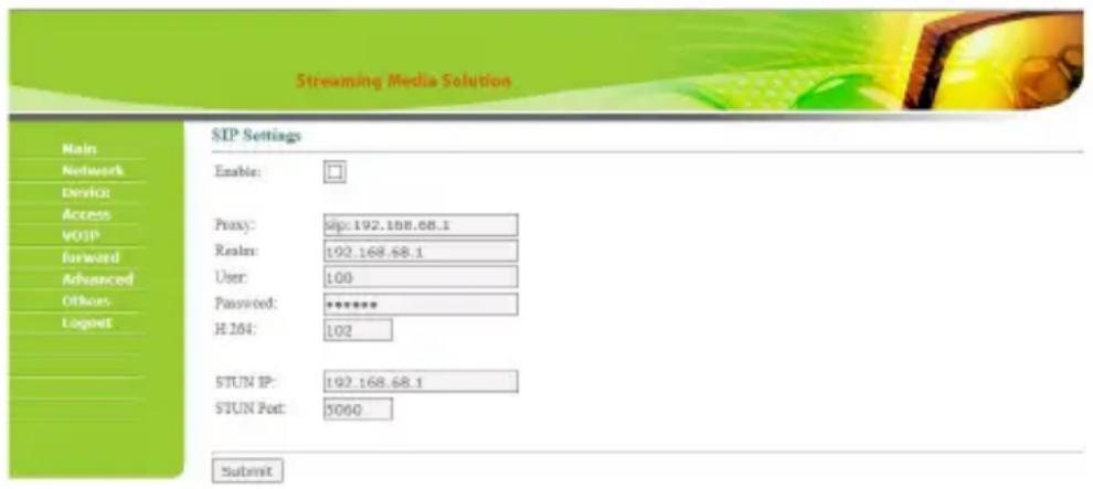
Proxy: URL of SIP proxy server in format: sip:ip or sip:domain name.
Realm: realm of the device, usually the same as IP or domain name.
User name: refers to the name of the SIP proxy server, provided by the SIP proxy server administrator.
Password: the password to access the SIP proxy server, provided by the SIP proxy server administrator.
STUN IP and Port refer to the IP and port of public server for NAT traversal of audio and video.
Once this is set up, click the button "Submit" to enable new settings.
6. Call Forwarding
Click the icon "Forward" on the left side of the page to enter the interface as shown below:
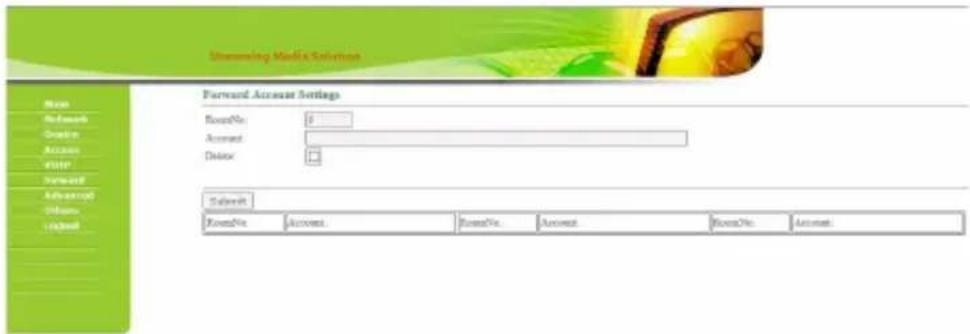
The room number can be bound with the telephone number. When a visitor calls but there is no answer within 25 seconds, the system will automatically forward the call to the phone. Specific steps are as follows:
- Enter the room number first, then enter the phone number you want to bind;
- To delete this account, check the box;
- Once this is set up, click the button "Submit" to enable new settings.
(Note: This item requires support of extension module or local SIP service provider.)
7. Advanced Settings
Click the icon "Advanced" on the left side of the page to enter the interface as shown below:
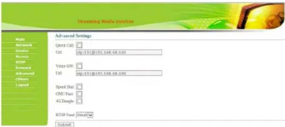
Quick Call: Check the box to enable this function. It refers to the call to management center. Enter the SIP address of specified management center device in the box after URL. The device can be indoor monitor or SIP phone of other manufacturers.
Check the box of Voice GW to enable voice gateway. The settings are as follows:
- Connect LAN port of voice module to the computer through the switch, set the computer's IP address to 192.168.2.*, open IE browser, and enter http:
//192.168.2.1 and default password "admin" to the setup interface; - According to the situation of used internet, assign appropriate IP address to WAN port of voice module (IP of WAN port cannot be in the same network segment as the one of LAN port. If WAN port is set to 192.168.2.* , the gateway of LAN port will be adjusted automatically rather than 192.168.2.1). Enable the access permission of WAN port and click "Apply".
- FXO port settings: set the SIP user ID of the port, set DTMF mode to RFC2833 and click "Apply".
- IP address of WAN port for voice gateway is in the URL for system development module of outdoor panel. The final port No. is default port of the system. The format of URL bar is: [SIP user ID of FXS port] @ [IP of WAN Port]: 5062.
- Once this is set up, click "Submit" to enable new settings.
Speed Dial: press a number key to call directly; ONU
Pass: check the box to enable ONU settings; 4G
Dongle: check the box to enable 4G Internet;
RTSP Feed: check the box to bind media address of third-party video network management.
Once this is set up, click "Submit" to enable new settings.
8. Other Settings
Click the icon "Others" on the left side of the page to enter the interface as shown below:
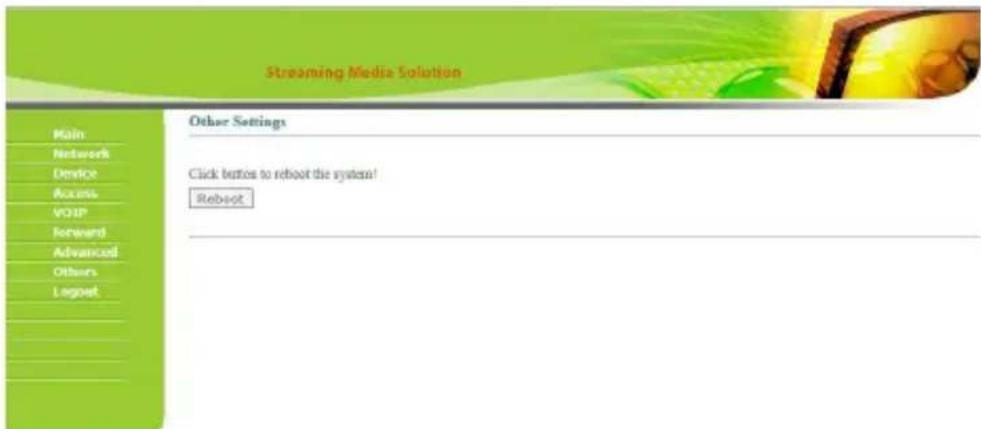
Click Reboot to restart the system.
9. Logout
Click the icon "Logout" on the left side. In next page, click the icon "Submit" to log out the system.
![Streaming Media Solutions Main Networks Device Access User Reward Advanced Others Logout User Logout Please click [Submit] to logout user! Submit](/content/2026/05/1060490/images/141b4978fffe16753b520f574e77be7fc426afabba77679c3dbbb087b5ab9bd2.jpg)
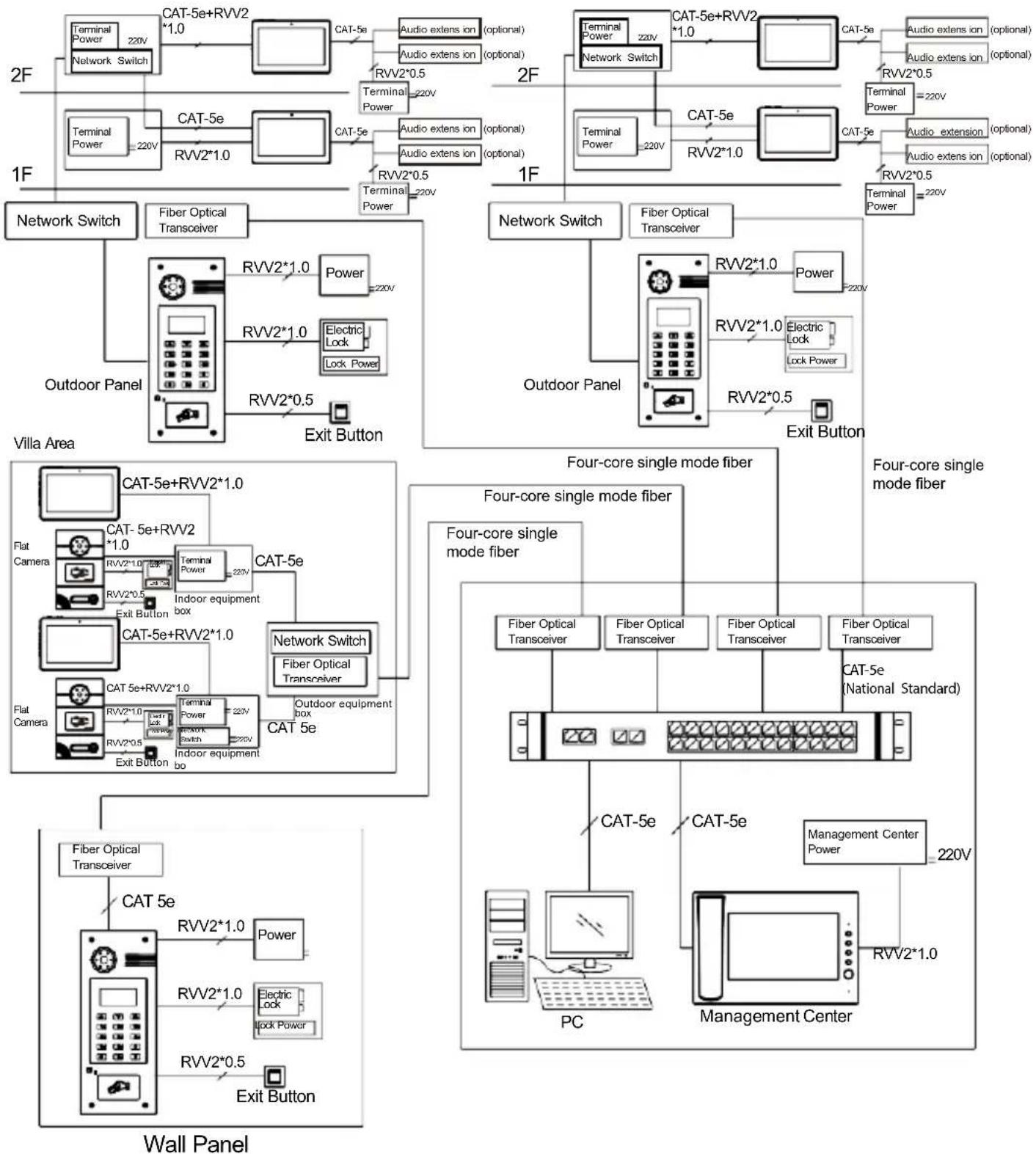
System connection diagram
flowchart
graph TD
    subgraph Wall Panel
        A["Wall Panel"] --> B["FB"]
        B --> C["FC"]
        C --> D["Network Switch"]
        D --> E["Fiber Optical Transceiver"]
        E --> F["Outdoor Panel"]
        F --> G["Villa Area"]
        G --> H["FB Optical Transceiver"]
        H --> I["PC"]
        I --> J["Management Center"]
    end

    subgraph Villa Area
        K[" Villa Area"] --> L["FB Optical Transceiver"]
        L --> M["FC"]
        M --> N["Network Switch"]
        N --> O["Fiber Optical Transceiver"]
        O --> P["Outdoor Panel"]
        P --> Q["Villa Area"]

    subgraph Wall Panel
        R["Wall Panel"] --> S["FB Optical Transceiver"]
        S --> T["PC"]
        T --> U["Management Center"]
    end

    subgraph Villa Area
        V[" Villa Area"] --> W["FB Optical Transceiver"]
        W --> X["Fiber Optical Transceiver"]
        X --> Y["Outdoor Panel"]
        Y --> Z["Villa Area"]

    subgraph Wall Panel
        AA["Wall Panel"] --> AB["FB Optical Transceiver"]
        AB --> AC["Fiber Optical Transceiver"]
        AC --> AD["Outdoor Panel"]
        AD --> AE["Villa Area"]

    subgraph Wall Panel
        AF["Wall Panel"] --> AG["FB Optical Transceiver"]
        AG --> AH["Fiber Optical Transceiver"]
        AH --> AI["Outdoor Panel"]
        AI --> AJ["Villa Area"]

    subgraph Wall Panel
        AK["Wall Panel"] --> AL["FB Optical Transceiver"]
        AL --> AM["Fiber Optical Transceiver"]
        AM --> AN["Outdoor Panel"]
        AN --> AO["Villa Area"]

    subgraph Wall Panel
        AP["Wall Panel"] --> AQ["FB Optical Transceiver"]
        AQ --> AR["Fiber Optical Transceiver"]
        AR --> AS["Outdoor Panel"]
        AS --> AT["Villa Area"]

    subgraph Wall Panel
        AU["Wall Panel"] --> AV["FB Optical Transceiver"]
        AV --> AW["Fiber Optical Transceiver"]
        AW --> AX["Outdoor Panel"]
        AX --> AY["Villa Area"]

    subgraph Wall Panel
        AX --> AZ["FB Optical Transceiver"]
        AZ --> BA["Fiber Optical Transceiver"]
        BA --> BB["Outdoor Panel"]
        BB --> BC["Villa Area"]

    subgraph Wall Panel
        BD["Wall Panel"] --> BE["FB Optical Transceiver"]
        BE --> BF["Fiber Optical Transceiver"]
        BF --> BG["Outdoor Panel"]
        BG --> BH["Villa Area"]

    subgraph Wall Panel
        BI["Wall Panel"] --> BJ["FB Optical Transceiver"]
        BJ --> BK["Fiber Optical Transceiver"]
        BK --> BL["Outdoor Panel"]
        BL --> BM["Villa Area"]

    subgraph Wall Panel
        BJ --> BN["Fiber Optical Transceiver"]
        BN --> BO["Fiber Optical Transceiver"]
        BO --> BP["Outdoor Panel"]
        BP --> BQ["Villa Area"]

    subgraph Wall Panel
        BR["Wall Panel"] --> BS["Fiber Optical Transceiver"]
        BS --> BT["Fiber Optical Transceiver"]
        BT --> BU["Outdoor Panel"]
        BU --> BV["Villa Area"]

    subgraph Wall Panel
        BS --> BW["Fiber Optical Transceiver"]
        BW --> BX["Fiber Optical Transceiver"]
        BX --> BY["Outdoor Panel"]
        BY --> BZ["Villa Area"]

    subgraph Wall Panel
        BW --> BZ["Fiber Optical Transceiver"]
        BZ --> CA["Fiber Optical Transceiver"]
        CA --> CB["Outdoor Panel"]
        CB --> CC["Villa Area"]

    subgraph Wall Panel
        BW --> CBZ["Fiber Optical Transceiver"]
        CBZ --> DA["Fiber Optical Transceiver"]
        DA --> DB["Outdoor Panel"]
        DB --> DC["Villa Area"]

    subgraph Wall Panel
        BW --> DCZ["Fiber Optical Transceiver"]
        DCZ --> DE["Fiber Optical Transceiver"]
        DE --> DF["Outdoor Panel"]
        DF --> DG["Villa Area"]

    subgraph Wall Panel
        BW --> DCZL["Fiber Optical Transceiver"]
        DCZL --> DE2["Fiber Optical Transceiver"]
        DE2 --> DF2["Fiber Optical Transceiver"]

    subgraph Wall Panel
        DCZL1["Fiber Optical Transceiver"]
        DCZL2["Fiber Optical Transceiver"]
        DCZL3["Fiber Optical Transceiver"]
    end

    subgraph Wall Panel
        DCZL4["Fiber Optical Transceiver"]
        DCZL5["Fiber Optical Transceiver"]
    end

    subgraph Wall Panel
        DCZL6["Fiber Optical Transceiver"]
        DCZL7["Fiber Optical Transceiver"]
    end

    subgraph Wall Panel
        DCZL8["Fiber Optical Transceiver"]
        DCZL9["Fiber Optical Transceiver"]
    end

    subgraph Wall Panel
        DCZL10["Fiber Optical Transceiver"]
        DCZL11["Fiber Optical Transceiver"]
    end

    subgraph Wall Panel
        DCZL12["Fiber Optical Transceiver"]
        DCZL13["Fiber Optical Transceiver"]
    end

    subgraph Wall Panel
        DCZL14["Fiber Optical Transceiver"]
        DCZL15["Fiber Optical Transceiver"]
    end

    subgraph Wall Panel
        DCZL16["Fiber Optical Transceiver"]
        DCZL17["Fiber Optical Transceiver"]
    end

    subgraph Wall Panel
        DCZL18["Fiber Optical Transceiver"]
        DCZL19["Fiber Optical Transceiver"]
    end

    subgraph Wall Panel
        DCZL20["Fiber Optical Transceiver"]
        DCZL21["Fiber Optical Transceiver"]
    end

    subgraph Wall Panel
        DCZL22["Fiber Optical Transceiver"]
        DCZL23["Fiber Optical Transceiver"]
    end

    subgraph Wall Panel
        DCZL24["Fiber Optical Transceiver"]
        DCZL25["Fiber Optical Transceiver"]
    end

    subgraph Wall Panel
        DCZL26["Fiber Optical Transceiver"]
        DCZL27["Fiber Optical Transceiver"]
    end

    subgraph Wall Panel
        DCZL28["Fiber Optical Transceiver"]
        DCZL29["Fiber Optical Transceiver"]
    end

    subgraph Wall Panel
        DCZL30["Fiber Optical Transceiver"]
        DCZL31["Fiber Optical Transceiver"]
    end

    subgraph Wall Panel
        DCZL32["Fiber Optical Transceiver"]
        DCZL33["Fiber Optical Transceiver"]
    end

    subgraph Wall Panel
        DCZL34["Fiber Optical Transceiver"]
        DCZL35["Fiber Optical Transceiver"]
    end

    subgraph Wall Panel
        DCZL36["Fiber Optical Transceiver"]
        DCZL37["Fiber Optical Transceiver"]
    end

    subgraph Wall Panel
        DCZL38["Fiber Optical Transceiver"]
        DCZL39["Fiber Optical Transceiver"]
    end

    subgraph Wall Panel
        DCZL40["Fiber Optical Transceiver"]
        DCZL41["Fiber Optical Transceiver"]
    end

    subgraph Wall Panel
        DCZL42["Fiber Optical Transceiver"]
        DCZL43["Fiber Optical Transceiver"]
    end

    subgraph Wall Panel
        DCZL44["Fiber Optical Transceiver"]
        DCZL45["Fiber Optical Transceiver"]
    end

    subgraph Wall Panel
        DCZL46["Fiber Optical Transceiver"]
        DCZL47["Fiber Optical Transceiver"]
    end

    subgraph Wall Panel
        DCZL48["Fiber Optical Transceiver"]
        DCZL49["Fiber Optical Transceiver"]
    end

    subgraph Wall Panel
        DCZL50["Fiber Optical Transceiver"]
        DCZL51["Fiber Optical Transceiver"]
    end

    subgraph Wall Panel
        DCZL52["Fiber Optical Transceiver"]
        DCZL53["Fiber Optical Transceiver"]
    end

    subgraph Wall Panel
        DCZL54["Fiber Optical Transceiver"]
        DCZL55["Fiber Optical Transceiver"]
    end

    subgraph Wall Panel
        DCZL56["Fiber Optical Transceiver"]
        DCZL57["Fiber Optical Transceiver"]
    end

    subgraph Wall Panel
        DCZL58["Fiber Optical Transceiver"]
        DCZL59["Fiber Optical Transceiver"]
    end

    subgraph Wall Panel
        DCZL60["Fiber Optical Transceiver"]
        DCZL61["Fiber Optical Transceiver"]
    end

    subgraph Wall Panel
        DCZL62["Fiber Optical Transceiver"]
        DCZL63["Fiber Optical Transceiver"]
    end

    subgraph Wall Panel
        DCZL64["Fiber Optical Transceiver"]
        DCZL65["Fiber Optical Transceiver"]
    end

    subgraph Wall Panel
        DCZL66["Fiber Optical Transceiver"]
        DCZL67["Fiber Optical Transceiver"]
    end

    subgraph Wall Panel
        DCZL68["Fiber Optical Transceiver"]
        DCZL69["Fiber Optical Transceiver"]
    end

    subgraph Wall Panel
        DCZL70["Fiber Optical Transceiver"]
        DCZL71["Fiber Optical Transceiver"]
    end

    subgraph Wall Panel
        DCZL72["Fiber Optical Transceiver"]
        DCZL73["Fiber Optical Transceiver"]
    end

    subgraph Wall Panel
        DCZL74["Fiber Optical Transceiver"]
        DCZL75["Fiber Optical Transceiver"]
    end

    subgraph Wall Panel
        DCZL76["Fiber Optical Transceiver"]
        DCZL77["Fiber Optical Transceiver"]
    end

    subgraph Wall Panel
        DCZL78["Fiber Optical Transceiver"]
        DCZL79["Fiber Optical Transceiver"]
    end

    subgraph Wall Panel
        DCZL80["Fiber Optical Transceiver"]
        DCZL81["Fiber Optical Transceiver"]
    end

    subgraph Wall Panel
        DCZL82["Fiber Optical Transceiver"]
        DCZL83["Fiber Optical Transceiver"]
    end

    subgraph Wall Panel
        DCZL84["Fiber Optical Transceiver"]
        DCZL85["Fiber Optical Transceiver"]
    end

    subgraph Wall Panel
        DCZL86["Fiber Optical Transceiver"]
        DCZL87["Fiber Optical Transceiver"]
    end

    subgraph Wall Panel
        DCZL88["Fiber Optical Transceiver"]
        DCZL89["Fiber Optical Transceiver"]
    end

    subgraph Wall Panel
        DCZL90["GPTC 1.0V / 2.0V"] --> Y["Exit Button"]

    end
Wiring diagram of outdoor panel
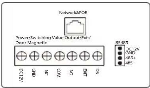
VE01-B22L/VE01-B23L
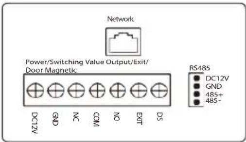
VE01-B22L/VE01-B23L
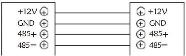
1. RS485 interface
It can connect to the equipment with RS485 interface.
RS485 interface can output 12V/100mA power. Connection of +12V isn't required if it is unused.
RS485 interface
RS485 equipment
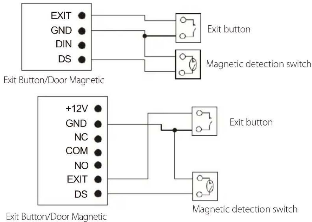
2.Exit Button/Door Magnetic Switch
Connect with Exit button and door magnetic switch; DIN is reserved terminal, please don't connect it.
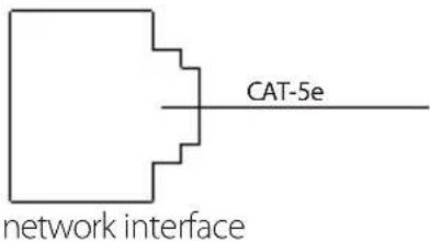
3. Network Interface
Connect to management center, indoor monitor or other network device through network switch.
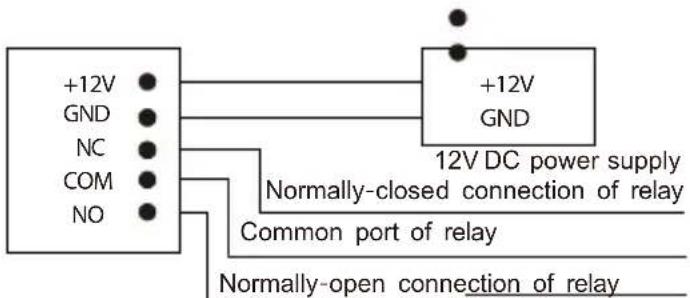
4. Power/Switching value output
Connect power interface of outdoor panel to 12V DC power. Switching value output connects with electric lock. Independent power supply is required for the lock.

chemical
Simple diagram of a positively charged particle connected to a negatively charged particle via an electron and a curved arrow, labeled 'Power'5. RS485/Exit/Door Magnetic
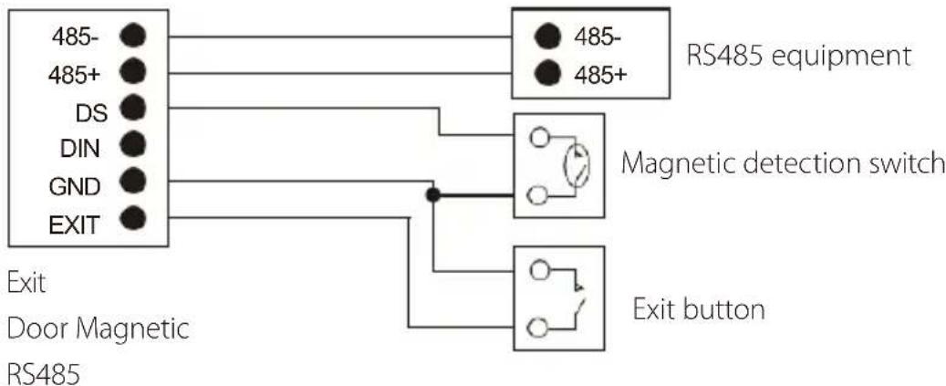
flowchart
graph TD
    A["485-"] --> B["RS485 equipment"]
    C["485+"] --> B
    D["DS"] --> B
    E["DIN"] --> B
    F["GND"] --> B
    G["EXIT"] --> B
    H["Magnetic detection switch"] --> I["Switch with ○"]
    J["Exit door Magnetic RS485"] --> K["Switch with ○"]
    L["Exit button"] --> M["Switch with ○"]
- RS485/Switching Value Output/Exit/Door Magnetic
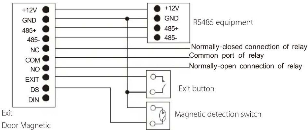
flowchart
graph TD
    A["+12V"] --> B["RS485 equipment"]
    C["GND"] --> B
    D["485+"] --> B
    E["485-"] --> B
    F["NC"] --> G["Common port of relay"]
    H["COM"] --> G
    I["NO"] --> G
    J["EXIT"] --> K["Exit button"]
    L["DS"] --> K
    M["DIN"] --> K
    N["Exit Door Magnetic"] --> O["Magnetic detection switch"]
    style A fill:#000,stroke:#fff,color:#fff
    style C fill:#000,stroke:#fff,color:#fff
    style D fill:#000,stroke:#fff,color:#fff
    style E fill:#000,stroke:#fff,color:#fff
    style F fill:#000,stroke:#fff,color:#fff
    style H fill:#000,stroke:#fff,color:#fff
    style I fill:#000,stroke:#fff,color:#fff
    style J fill:#000,stroke:#fff,color:#fff
    style L fill:#000,stroke:#fff,color:#fff
    style M fill:#000,stroke:#fff,color:#fff
    style N fill:#000,stroke:#fff,color:#fff
RS485
Switching Value Output
7. Wiegand interface
Wiegand output interface: connect to card reader through the Wiegand interface;
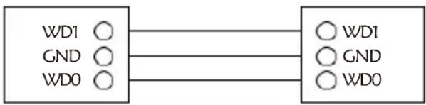
flowchart
graph LR
    A["WD1"] --> B["WD1"]
    C["GND"] --> D["GND"]
    E["WD0"] --> F["WD0"]
Wiegand interface
Card reader
Installation instructions
Model:VE01-B22L
| Appearance dimension drawing | Installation diagram |
| Product size: 192x116x47mm Built-in box size:100X177X45mm Trepanning size:105x182x52mm | Drain hole Built-in Box VE01-B22L |
Model:VE01-B23L
| Appearance dimension drawing | Installation diagram |
| Product size: 192x116x47mm Built-in box size:100X177X45mm Trepanning size:105x182x52mm | Drain hole Built-in Box VE01-B23L |
Installation notes:
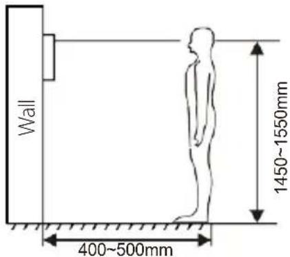
[Suggestion]: During the
installation, the display screen
should be 1450\~1550mm from the ground.
Troubleshooting
Some common failures and troubleshooting methods are listed for your reference. In case of failure which cannot be repaired, do not disassemble or repair the product by yourself. Please contact the after-sales service department.
When outdoor panel fails to call indoor monitor:
a. When setting villa outdoor panel, please make sure building No. and unit No. of outdoor panel are the same as the ones of indoor monitor;
b. Please check whether the network is connected;
c. Please check if there are any security settings for the network, such as VLAN configuration;
d. Indoor monitor cannot be set as sub device only. Main device is required.
Safety & Precautions
Safety & Precautions
To protect you and others from harm or protect your device from damage, please read the following information before using your device.
Do not install equipment in the following areas:
- Do not install equipment in high temperature, humidity, near the magnetic field, such as generators, transformers or magnets, etc.
- Do not place the equipment near the heating items such as the electric heater or the liquid container.
- Do not place the device directly in the sun or near the heat source, which may cause the body to be discolored or deformed.
- Do not install the equipment in an unstable position to avoid the property losses or personal injury caused by the falling of device.
Prevent electric shock, fire and explosion
- Do not use damaged power cord, plug or loose power outlet.
- Do not touch the power cord with wet hands or unplug the power source by pulling the power supply.
- Do not bend or damage the power cord.
- Do not touch the equipment with wet hands. Do
• not let the power slide, or cause a collision. - Do not use power supply without manufacturer approval. Do not
- splash water or other liquids into the equipment.
Clean surface
- Use a soft cloth dipped in a small amount of water to clean the surface of the machine and dry it with a dry cloth.
Other matters needing attention
- In order to prevent damage to the paint or housing, do not expose the device to chemical products, such as thinner, gasoline, alcohol, insect repellant, sunscreen, or pesticides, etc.
- Do not beat or hit the device with a hard object.
- Do not disassemble, refit or modify the device at your own discretion. The arbitrary modification is not covered under warranty. When any repair required, please contact the customer service center.
- When the device emits abnormal sound, smell or smoke, unplug the power immediately and contact the customer service center in time.
- If you do not use the device for a long time, it is recommended to unplug the power adapter, take out memory card and put the device in a dry environment.
- Index
- Product description
- Application:
- Product appearance
- Basic function
- Technical parameter
- Package contents
- Basic operation
- Call indoor monitor
- Unlocking by card
- Unlocking by access password
- WEB settings
- Network Settings
- Device Settings
- Access Settings
- Card registration
- SIP Settings
- Call Forwarding
- Advanced Settings
- Other Settings
- Logout
- System connection diagram
- Wiring diagram of outdoor panel
- RS485 interface
- 2.Exit Button/Door Magnetic Switch
- Network Interface
- Power/Switching value output
- RS485/Exit/Door Magnetic
- Wiegand interface
- Installation instructions
- Troubleshooting
- Safety & Precautions
- Prevent electric shock, fire and explosion
- Clean surface
- Other matters needing attention
Brand : ZKTeco
Model : VE01-B22L
Category : Intercom