TC950 - Heating Escea - Free user manual and instructions
Find the device manual for free TC950 Escea in PDF.


| Product Type | Direct Vent Gas Fireplace |
| Model | TC950 |
| Brand | Escea |
| Dimensions (H x W x D) | 580 mm x 1000 mm x 380 mm |
| Weight | 75 kg |
| Power Supply | 240 V AC, 50 Hz |
| Fuel Type | Natural Gas or LPG |
| Heat Output | 8.5 kW (max) |
| Efficiency | 78% (NET) |
| Flue Diameter | 150 mm |
| Glass Type | Ceramic tempered glass |
| Control Method | Remote control with thermostat |
| Main Functions | Direct vent, variable flame height, pilot light (standing or intermittent), fan forced heat distribution |
| Maintenance | Clean glass with non-abrasive cleaner, inspect flue annually, replace batteries in remote |
| Safety Features | Flame failure device, overheat protection, safety screen, child lock (remote) |
| Spare Parts | Ceramic glass, burner assembly, pilot assembly, remote control, fan motor |
| Repairability | Modular design; most components replaceable by authorized technicians |
| Certifications | CE, Gas Safe, AS/NZS 5263 |
| Warranty | 2 years (parts and labor) |
Frequently Asked Questions - TC950 Escea
User questions about TC950 Escea
0 question about this device. Answer the ones you know or ask your own.
Ask a new question about this device
Download the instructions for your Heating in PDF format for free! Find your manual TC950 - Escea and take your electronic device back in hand. On this page are published all the documents necessary for the use of your device. TC950 by Escea.
USER MANUAL TC950 Escea
Installation Instructions and User Guide
WARRANTY REPAIR AND ANNUAL SERVICING
Please contact Escea if you require warranty work. Warranty repair work must be carried out by a recognised Escea woodfire installer. It is recommended that recognised Escea Wood Fire Installers are also used to carry out annual servicing requirements (particularly during the warranty period). For contact details of recognised Escea Wood Fire Technicians in your area, or for replacement parts, please contact the retailer from whom the appliance was purchased from, or visit our website.
All installation work must comply to AS/NZS 2918:2018 Domestic solid fuel burning appliances- Installation AND these installation instructions. Any work undertaken that does not comply to AS/NZS 2918:2018 AND these installation instructions will not qualify for the Escea warranty. Escea will not be accountable for any unsafe installation that does not comply to AS/NZS 2918:2018.
Manufactured by: Escea Ltd, PO Box 5277 Dunedin NZ, Ph: +64 3 478 8220
For contact details of your local Escea distributor or dealer, please visit www.escea.com, call 0800 173 000, or email us at info@escea.com.
From Australia, please visit www.escea.com.au, call AU: 1800 460 832 or WA: 1800 730 140, or email us at info@escea.com
CONTENTS
| A | Safety | Information | |
| B | Product | Details | |
| C | Installation | Requirements | |
| D | Installation | Procedure | |
| E | Flue | System | Installation |
| F | Operation | Guide | |
| G | Maintenance | and | Servicing |
| H | Troubleshooting | ||
| I General Warranty Terms & Conditions | |||
| J Service History & Data Plate | |||
NOTICE
DO NOT DISCARD THIS MANUAL
IMPORTANT OPERATING AND MAINTENANCE INSTRUCTIONS INCLUDED.
READ, UNDERSTAND AND FOLLOW THESE INSTRUCTIONS FOR SAFE INSTALLATION AND OPERATION.
LEAVE THIS MANUAL WITH PARTY RESPONSIBLE FOR USE AND OPERATION.
WARNING
IF THE INFORMATION IN THESE INSTRUCTIONS IS NOT FOLLOWED EXACTLY,
A FIRE OR EXPLOSION MAY RESULT CAUSING PROPERTY DAMAGE, PERSONAL INJURY OR DEATH. IMPROPER INSTALLATION, ADJUSTMENT, AERATION, SERVICE OR MAINTENANCE CAN CAUSE INJURY OR PROPERTY DAMAGE, BODILY INJURY OR EVEN DEATH. PLEASE READ ENTIRE MANUAL BEFORE YOU INSTALL AND USE YOUR APPLIANCE.
THIS APPLIANCE IS NOT TO BE USED BY PERSONS (INCLUDING CHILDREN) WITH REDUCED PHYSICAL, SENSORY, OR MENTAL CAPABILITIES, OR LACK OF EXPERIENCE AND KNOWLEDGE, UNLESS THEY HAVE BEEN GIVEN SUPERVISION OR INSTRUCTION CONCERNING USE OF THE APPLIANCE BY A PERSON RESPONSIBLE FOR THEIR SAFETY.
WARNING: THIS APPLIANCE AND FLUE SYSTEM MUST BE INSTALLED IN ACCORDANCE WITH AS/NZS 2918:2001 AND THE APPROPRIATE REQUIREMENTS
OF ANY RELEVANT LOCAL/NATIONAL BUILDING CODES.
WARNING: APPLIANCES INSTALLED SHALL COMPLY WITH THE REQUIREMENTS OF AS/NZS 4013 WHERE REQUIRED BY THE REGULATORY AUTHORITY (I.E. THE APPLIANCE SHALL BE IDENTIFIABLE BY A COMPLIANCE PLATE WITH THE MARKING 'TESTED TO AS/NZA 4013')
ANY MODIFICATION OF THE APPLIANCE THAT HAS NOT BEEN APPROVED IN WRITING BY THE TESTING AUTHORITY IS CONSIDERED TO BE IN BREACH OF ANY APPROVAL GRANTED FOR COMPLIANCE WITH AS/NZS 4012:2014 & AS/NZS 4013:2014.
IF THE SUPPLY CORD IS DAMAGED, IT MUST BE REPLACED BY THE MANUFACTURER, ITS SERVICE AGENT OR SIMILARLY QUALIFIED PERSONS IN ORDER TO AVOID A HAZARD.
CAUTION: THIS APPLIANCE SHOULD BE MAINTAINED AND OPERATED AT ALL TIMES IN ACCORDANCE WITH THESE INSTRUCTIONS:
- The appliance should be allowed to cool before servicing.
- Do not operate without fully assembling all components.
- Risk of cuts and abrasions. Wear protective gloves and safety glasses during installation. Sheet metal edges may be sharp.
- Do not operate appliance before reading and understanding operating instructions. Failure to operate appliance according to operating instructions could cause fire or injury.
CAUTION: MIXING OF APPLIANCE OR FLUE SYSTEM COMPONENTS FROM DIFFERENT SOURCES OR MODIFYING THE DIMENSIONAL SPECIFICATION OF COMPONENTS MAY RESULT IN HAZARDOUS CONDITIONS. WHERE SUCH ACTION IS CONSIDERED, THE DISTRIBUTOR: ESCEA LTD SHOULD BE CONSULTED AT THE FIRST INSTANCE.
CAUTION: CRACKED AND BROKEN COMPONENTS. E.G. GLASS PANELS, MAY RENDER THIS INSTALLATION UNSAFE.
CAUTION: THIS APPLIANCE SHOULD NOT BE OPERATED WITH CRACKED GLASS.
- This appliance can be very hot when burning.
- Combustible materials such as firewood, wet clothing, etc. placed too close can catch fire
- Young children and elderly people should be carefully supervised when they are in the same room as the appliance. Toddlers, young children and others may be susceptible to accidental contact burns. A physical barrier is recommended if there are at risk individuals in the house. To restrict access to an appliance or stove, install an adjustable safety gate to keep toddlers, young children and other at risk individuals out of the room and away from hot surfaces. Children and pets must be prevented from touching the appliance when it is hot.
- Clothing or other flammable material should not be placed on or near the appliance.
- Due to high temperatures, the appliance should be located out of traffic and away from furniture and draperies.
- Ensure you have incorporated adequate safety measure to protect infants/toddlers from touching hot surfaces.
- Even after the fire within the appliance is out, the glass and/or screen will remain hot for an extended period of time.
- Keep the packaging material out of reach of children and dispose of the material in a safe manner. As with all plastic bags, these are not toys and should be kept away from children and infants.
- Operate only with the door tightly closed unless
instructed otherwise.
- Do not strike or slam shut the appliance door. Do not put excessive weight on the door.
- This appliance is designed to burn natural hardwood only for Australian models.
- Do not burn green or freshly cut wood.
CAUTION: THE USE OF SOME TYPES OF PRESERVATIVE-TREATED WOOD AS FUEL CAN BE HAZARDOUS.
- Your appliance requires periodic maintenance and cleaning. Failure to maintain your appliance may lead to smoke spillage into your home.
- Do not start a fire with chemicals or fluids such as gasoline, engine oil, etc.
- Do not burn treated wood, coal, charcoal, coloured paper, cardboard, solvents or garbage.
- Do not let the appliance become hot enough for any part to glow red.
- Do not overload or over fire the appliance.
- Ashes must be disposed in a metal container with a tight lid and placed on a non-combustible surface well away from the home or structure until completely cool.
- Ensure clearances to combustibles are maintained when building a mantel or shelves above the appliance. Elevated temperatures on the wall or in the air above the appliance can cause melting, discolouration or damage to decorations, a TV, or other electronic components.
- The appliance must be installed using only the building materials as approved by the manufacturer.
- Ensure that there is always a socket installed within 1 meter of the product that is accessible after installation.
WARNING
HOT GLASS WILL CAUSE BURNS. DO NOT TOUCH GLASS UNTIL COOLED.
B1 Product Description
The TC950 is an indoor in-built wood fire.
B2 Specifications Table
| Fuel Type Hardwood | |
| Average particulate emissions | (g/kg) 1.00 |
| Overall average efficiency | (%) 61.88 |
| Maximum average heat output | (kW) 8.77 |
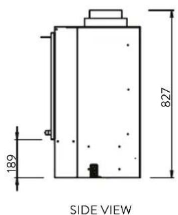
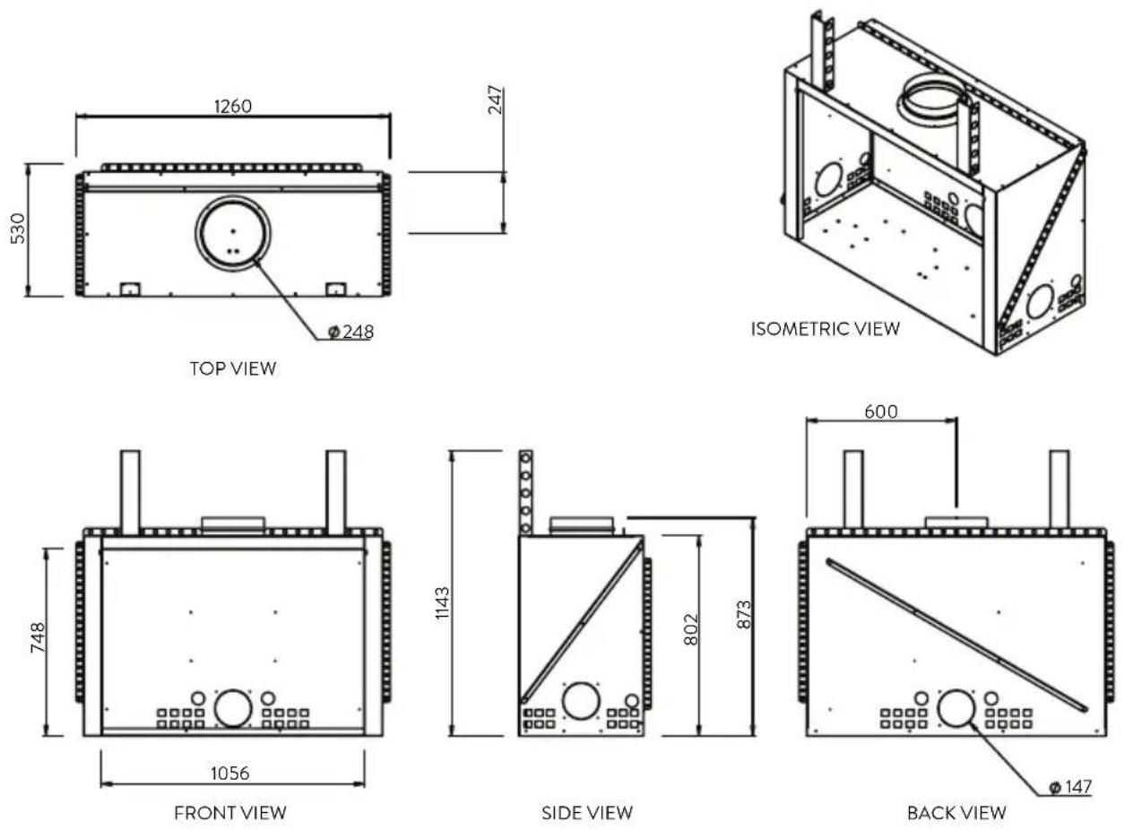
B3 Product Dimensions
Fire Dimensions:


natural_image
Isometric view diagram of a mechanical enclosure with a central knob and mounting brackets (no text or symbols)
TC950 Zero Clearance Kit Dimensions:
TC950 Linear Fascia Dimensions:

1069mm Width
TC950 Frameless Trim Dimensions
65mm trim depth


C1 Installation - General
WARNING
THE INSTALLATION OF THIS FIREPLACE, CONSTRUCTION OF THE FIREPLACE ENCLOSURE AND THE FINISHING AND COMMISSIONING OF THE INSTALLATION IS A HIGHLY SPECIALIST TASK. ONLY AHHA APPROVED/ACCREDITED TRADESMEN SHOULD BE USED (AHHA - AUSTRALIAN HOME HEATING ASSOCIATION). FAILURE TO FOLLOW THESE REQUIREMENTS WILL VOID ALL WARRANTY TERMS.
THIS APPLIANCE AND ITS COMPONENTS ARE DESIGNED TO BE INSTALLED AND OPERATED AS A SYSTEM. ANY ALTERATION TO OR SUBSTITUTION FOR ITEMS IN THIS SYSTEM, UNLESS ALLOWED BY THESE INSTALLATION INSTRUCTIONS, WILL VOID THE LISTING AND MAY VOID THE PRODUCT WARRANTY. IT MAY ALSO CREATE A HAZARDOUS INSTALLATION.
READ THROUGH THESE INSTRUCTIONS THROUGHLY BEFORE STARTING YOUR INSTALLATION AND FOLLOW THEM CAREFULLY THROUGHOUT YOUR PROJECT.
- Before beginning your installation, consult with your local building code agency or fire officials and insurance representative to ensure compliance.
- For the first two weeks use generous amounts of fuel and burn the appliance with the air control fully open for an hour as the appliance goes through a process of eliminating moisture in the steel and vermiculite panels. The initial heat output will be reduced while the moisture is being drawn from the appliance and it will be necessary to build several hot fires to remove this moisture.
WEAR GLOVES AND SAFETY GLASSES FOR PROTECTION
CAREFULLY FOLLOW THE INSTRUCTIONS FOR INSTALLATION AND USE. FAILURE TO DO SO MAY RESULT IN A FIRE, ESPECIALLY IF COMBUSTIBLES ARE TOO CLOSE TO THE APPLIANCE OR FLUE SYSTEM AND AIR SPACES ARE BLOCKED, PREVENTING THE FREE MOVEMENT OF COOLING AIR.
ESCEA ACCEPTS NO LIABILITY FOR IMPROPER INSTALLATION OR CONSEQUENTIAL DAMAGES.
Note: the appliance has been tested to AS/NZS 2918 Appendix B. The flue system has been tested to AS/NZS 2918 Appendix F.
C2 Cavity Construction Requirements
If installing into a cavity constructed from combustible material, the TC950 fireplace must be installed into the TC950 Zero Clearance Kit. For installation of the TC950 Zero Clearance Kit, the minimum cavity opening dimensions are 1265mm W x 580mm D, with an overall cavity height of 2400mm.
If installing into a non-combustible cavity, the TC950 Zero Clearance Kit is not required but the appliance must be installed to AS/NZS 2918.
C3 Floor Protector Requirements
If there is combustible flooring within 500mm of the appliance, a floor protector must be installed.
If there is combustible flooring (or any other combustible material) in front of the appliance (within 500mm), the base of the appliance must be raised by a minimum of 235mm from the floor. The base upon which the appliance sits on may be constructed of a suitably stable heat sensitive material (the base must not extend beyond the front of the appliance).
Additionally, a floor protector of any suitable heat resistant material must be installed to prevent any ash contacting the floor. The floor protector must extend not less than 300mm from the front of the appliance and not less than 200mm from each side of the appliance.

The floor to product height of 235mm can be reduced if the product is installed over an insulating, heat resistant floor complying with requirements of AS/NZS 2918:2018 section 3.3.3.
C4 Mantel and Side Wall Clearances
For mantels constructed out of combustible material, the mantel must be installed at a minimum of 500mm above the appliance opening, a minimum of 300mm either side of the appliance opening, and can protrude a maximum of 100mm from the front of the cavity.
Mantels constructed out of non-combustible material may be installed anywhere above the opening of the appliance.
For more advice on mantel material choice, please contact Escea's architectural advisory team.
Combustible mantels or adjacent walls that extend more than 100mm from the front of the cavity must be a minimum of 500mm away from the appliance opening.
Note: the appliance opening is defined as the inside face of the trim/ fascia.

C5 Electrical Requirements
The TC950 appliance comes with a pre-installed fan. Please ensure there is adequate wiring to the cavity before starting the installation. A socket can be placed either inside or outside the cavity. An isolation switch or RCD must be placed outside the cavity.
The power can be left on when the fire is not in use. The appliance has a built in thermal switch which will turn the fan on when the fire is in use, and switch the fan off when the appliance cools down.
C6 TV Installation Requirements
Please contact an Escea Architectural Advisor for any queries regarding installing a TV above your woodfire.
C7 Painted Wall Finish Installation Requirements
This installation scenario is for installation into a timber/ combustible cavity, with a painted wall finish.
The TC950 Zero Clearance Kit must be specified when the appliance is installed into a combustible cavity.
For this installation scenario, the appliance must be installed with the TC950 Linear Fascia.

The TC950 Zero Clearance Kit comes supplied with 40mm thick ‘Skamotec’ insulative panels. For this installation scenario, the top panel and side panels must be rebated to the dimensions shown. Use a handsaw to rebate the panels, ensuring the panels are adequately supported while cutting.
The front of the cavity must be covered with non-combustible wallboard. The sides of the cavity may be covered with combustible wallboard.
Non-combustible fibre cement sheeting should be placed in front of the ‘Skamotec’ insulation panels which provides a continuous substrate to plaster/ paint onto. Use the supplied schematics for cutting the fibre cement sheets.
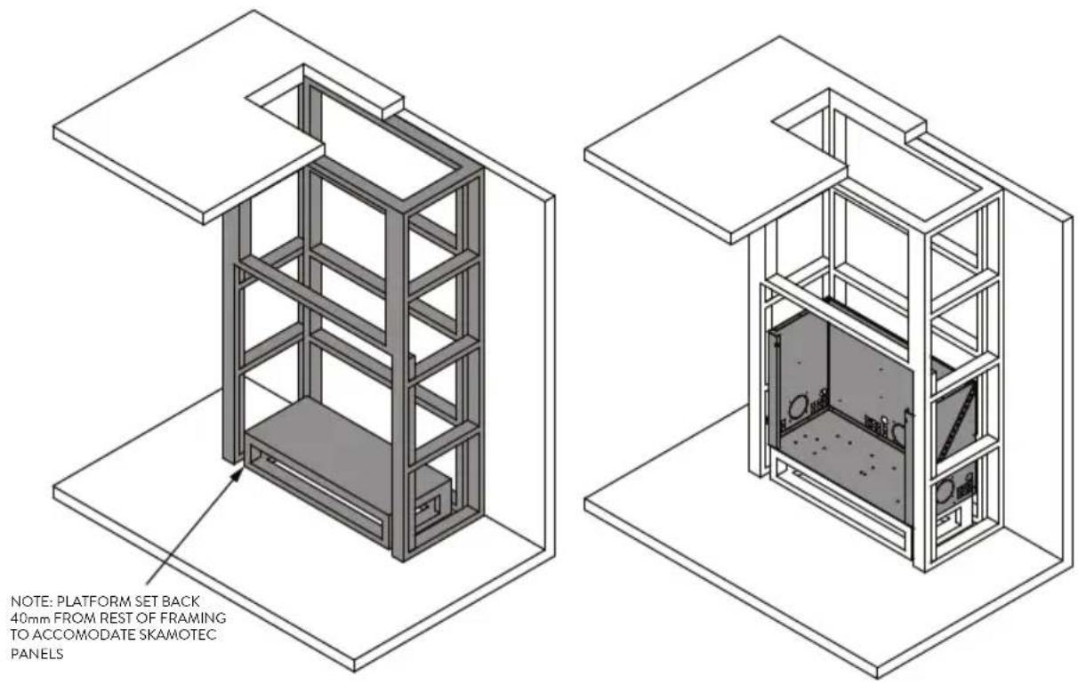
When constructing the base (for a combustible floor install), the base needs to be set back 40mm from the front of the cavity front, to accommodate the 'Skamotec' panels. The front of the Skamotec should be flush with the adjacent timber side framing.
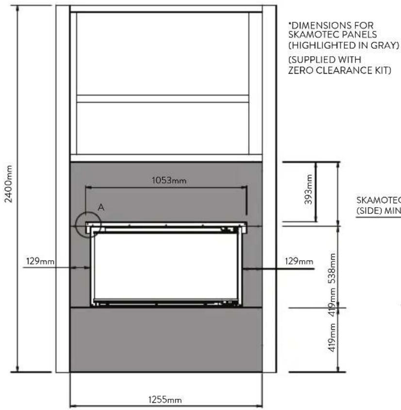
For a painted wall finish, the skamotec panels must be rebated on the top panel, side panel top LH corner and side panel top RH corner (to the dimensions shown).


*FIBRE CEMENT NON-COMBUSTIBLE WALLBOARD (HIGHLIGHTED IN LIGHT GRAY)
NOTE: STARRED ^+ DIMENSIONS ARE FOR 90 x 45mm FRAMING, ADJUST ACCORDINGLY IF USING THICKER FRAMING
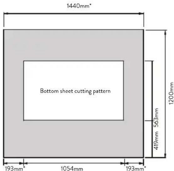


C8 Other Wall Finish Installation Requirements
This installation scenario is for installation into a timber/ combustible cavity, with other wallboard finishes such as tiles, brick, schist, stack stone, concrete etc. When installed with the Frameless Trim, the wallboard can be placed close to the trim (with a small clearance), giving a sleek, minimalist aesthetic. For more advice on wallboard choice, please contact Escea's Architectural Advisory team.
The TC950 Zero Clearance Kit must be specified when the appliance is installed into a combustible cavity.
For this installation scenario, the appliance must be installed with the TC950 Frameless Trim.
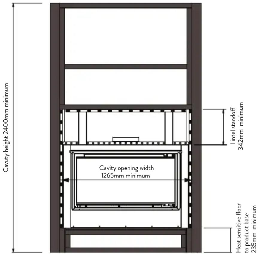
The TC950 Zero Clearance Kit comes supplied with 40mm thick ‘Skamotec’ insulative board panels. Note: the skamotec panels do not need to be modified for this install scenario.
The front of the cavity must be covered with non-combustible wallboard. The sides of the cavity may be covered with combustible wallboard.
Non-combustible fibre cement sheeting should be placed in front of the ‘Skamotec’ insulation panels which provides a continuous substrate to glue/secure the chosen wall material onto. Use the supplied schematics for cutting the fibre cement sheets.
When constructing the base (for a combustible floor install), the base needs to be set back 40mm from the front of the cavity front, to accommodate the 'Skamotec' panels. The front of the Skamotec should be flush with the adjacent timber side framing.

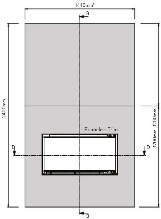
*FIBRE CEMENT
NON-COMBUSTIBLE
WALLBOARD
(HIGHLIGHTED IN LIGHT GRAY)
NOTE: STARRED* DIMENSIONS ARE FOR
90 x 45mm FRAMING, ADJUST ACCORDINGLY
IF USING THICKER FRAMING


Note: a minimum clearance of 6mm between the trim and the chosen wallboard is required to account for thermal expansion of the trim.

C9 Zero Clearance Kit Venting Requirements
The TC950 Zero Clearance Kit must be vented. There are multiple options for venting the kit depending on the install scenario. For all options, the hot air will exhaust through the 250mm dia galvanised liner sections to outside (which are supplied with the Escea Inbuilt Flue Kit).
Option 1 - Venting with Outside Air (Preferred)
Outside air can be drawn in by connecting a 150mm dia pipe from outside of the building to the zero clearance kit. It is recommended to use 150mm dia aluminium ducting (not supplied).
Venting air can be supplied from the back, or from either side of the zero clearance kit. A 150mm dia spigot is supplied with the kit. To attach it, take out the blanking plate from the desired panel and screw the the spigot to the panel using the supplied 4x Tek screws (1/4" driver size).

natural_image
Technical line drawings of industrial equipment components, including a control panel and two separate views of a mechanical housing (no text or symbols present)Option 2- Venting with Roof Cavity Air
Note: This option can only be used for cavity heights of 2.7m and under. Additionally, this option can only be used where there is no floor above the chimney cavity.
Air from the roof space can be utilised to vent the zero clearance kit down through the square holes located on the back panel and side panels.
Holes must be cut in the ceiling to allow roof space air into the enclosure. The minimum opening size is 2x 250mm x 150mm (or an equivalent surface area). Alternatively, you can have no ceiling inside the enclosure to allow as much air as possible into the zero clearance kit.


Option 3- Venting with Room Air
This option is not preferred - only consider this if both Options 1 and 2 cannot be applied.
This method will take away warm air from the room - this is undesirable.
Room air can be drawn into the cavity through vents on the side of the cavity. The minimum venting area is 17,670mm^2. Place the vents so that they are in line with the base of the zero clearance kit. There must be nothing inside the cavity that obscures the path of venting air to the zero clearance kit.
C10 Flue Clearances
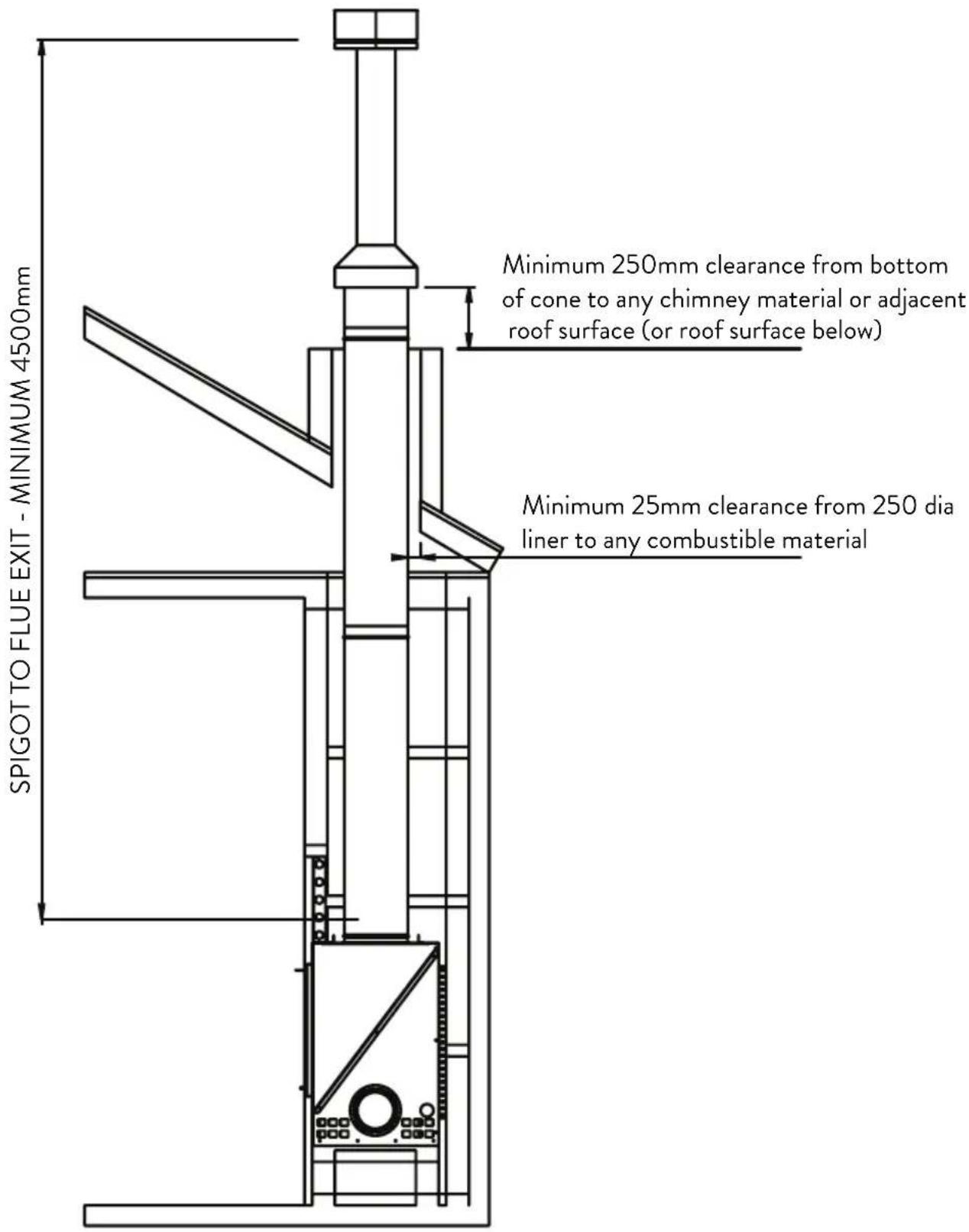
At any point above the enclosure, any combustible material MUST be separated from the 250mm diameter galvanised liner by a distance of no less than 25mm.
C11 Minimum Flue Length
The flue exit must be a minimum of 4.5m above the flue spigot. However in many cases, the flue may need to be taller to comply with external clearances.
C12 External Clearances:
The external clearances of the flue must comply to meet the requirements of AS/NZS 2918:2018 Section 4.9 - External Requirements
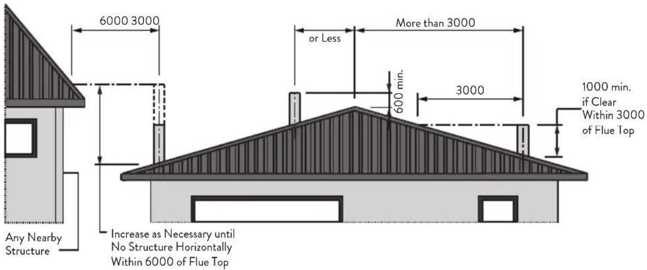
C13 Floor and Wall Penetration Requirements
All floor and wall penetrations for the flue system must comply with AS/NZS 2918:2018 section 4.6.3.
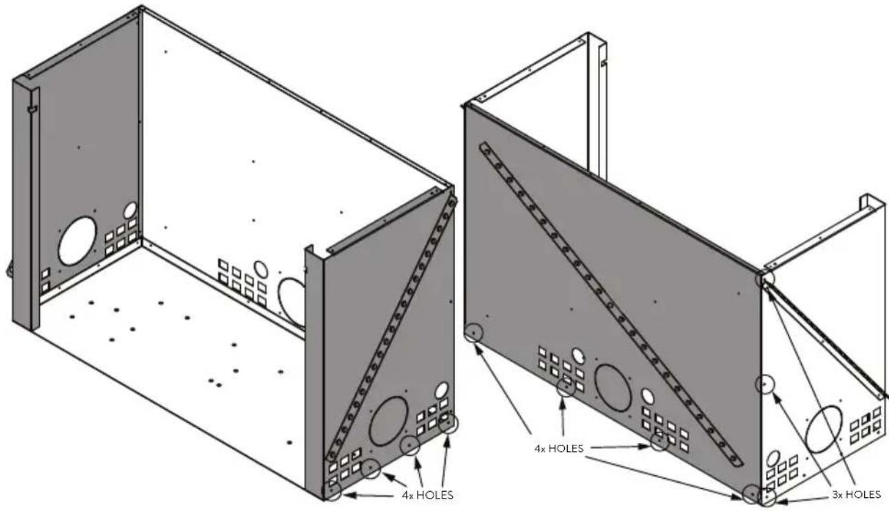
- Install 1x long standoff to the Zero Clearance Kit back panel using the supplied Tek screws (use 1/4" driver).
Install 1x short standoff bracket on the left side panel and 1x short standoff bracket on the right side panel using the Tek screws.

natural_image
Technical line drawings of three views of a rectangular electronic panel or enclosure with mounting holes and internal components (no text or symbols)- Partially construct the zero clearance kit outside of the framework with the base panel, back panel and side panels being installed first. Use provided Tek screws to assemble panels together.
- If installing over a combustible floor, construct a platform for the product. The dimensions of this platform must be a minimum of 1260mm x 530mm x 235mm (LxWxH). Note: the platform must not extend beyond the front of the appliance. Construct the left-side framework, right-side framework, rear framework and the top front framework for the enclosure.
Fix the platform to the ground. Then assemble the in-built enclosure by fixing the left-side framework, right-side framework and the top front framework together with the platform. Note: the front of the base will need to be set back 40mm from the front of the side frames.
Slide the partially built zero clearance kit into the constructed cavity so that it is sitting on the base.
If venting the zero clearance kit using method 1, make sure the 150mm spigot and venting pipe is connected to outside air. Refer to section C9 for venting requirements.
*Note: The platform must be seismically restrained to the floor.
*Note: Do not place any wall linings at this step.
- Place the fixing brackets for the Skamotec wall boards on the framework along the edges of the enclosure opening.
*Note: Ensure the front surface of the zero clearance kit flush with the mounting surface of the fixing brackets.


DETAIL K DETAIL L
-
Prepare the zero clearance kit for directing the power cord through. There are 4x circular cutouts at the bottom of the kit for directing the power cord. Cut a piece of the supplied rubber gasket to length and line the chosen hole. Note: this MUST be done to ensure electrical safety.
-
Prepare the fire for moving. Dismantle the wooden crate packaging. Remove the door, vermiculite pack and air baffle prior to moving to lighten the fire. Refer to section G4 for removing the door, and section G8 for removing the air baffle. Ensure that the power cable is secure to the product before moving.
Additionally, pre-drill 3x ∅3.3mm holes in the ∅150mm spigot, and 3x ∅3.3mm holes in the ∅200mm spigot in preparation for assembling the flue. It is easier to do this when the fire is outside of the enclosure.
- Slide the TC950 appliance through the enclosure opening and into the partially-built zero clearance kit until the front face of the fire is flush with the front of the zero clearance kit.
Direct the power cord out of the zero clearance kit through the insulated hole, and plug in to the socket.
Reach down between the appliance and the zero clearance kit to bolt the appliance to the base. Bolt through the 5mm thick right angled brackets at the base of the appliance.

natural_image
Isometric line drawing of a multi-level elevator system with a central mounted TV (no text or symbols)- Connect 3 pieces of the 1219mm long, ∅150mm flue pipe together to create a long flue pipe. Drill through the flue pipes and use a minimum of 3x stainless steel rivets to connect the flue pipes together.
Place ∅150mm flue spiders around each of the ∅150mm flue pipe. Tighten the screws and nuts to secure the spiders to the flue pipes. Drill through spider and flue pipes and use a minimum of 3x stainless steel rivets to secure the spiders to flue.
Connect 3x pieces of the 1219mm long, ∅200mm flue pipe together to create a long flue pipe. Drill through the flue pipes and use a minimum of 3x stainless steel rivets to connect the flue pipes together.
Place ∅200mm flue spiders around each of the ∅200mm flue pipe. Tighten the screws and nuts to secure the spiders to the flue pipes. Drill through spider and flue pipes and use a minimum of 3x stainless steel rivets to secure the spiders to the flue.
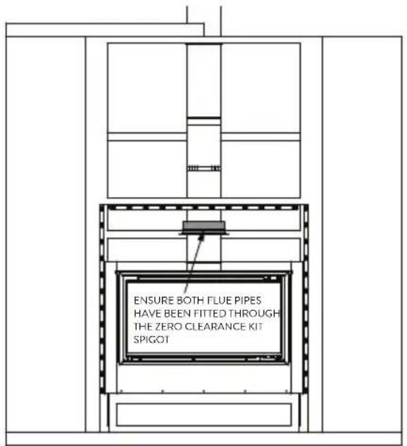
Note: Place the 250mm zero clearance kit spigot around the inner appliance spigots before placing the flue sections to the fire.
At this step, ensure that the hole in the roof is cut and flashed. For more details on flashings, please refer to section E.

- From the roof, Position the long ∅150mm flue pipe (with the crimped end pointing downwards) into the inner spigot. Use a minimum of 3x rivets to fasten the ∅150mm flue pipe through pre-drilled holes on the ∅150mm spigot.
Position the long ∅200mm flue pipe (with the crimped end pointing downwards) into the outer spigot. Use a minimum of 3x rivets to fasten the ∅200mm flue pipe through pre-drilled holes on the ∅200mm diameter spigot.
*Note: Ensure that the long ∅150mm flue pipe and the long ∅200mm flue pipe are fitted through the ∅250mm zero clearance kit spigot. Lift the 250mm diameter spigot when fixing the flue pipes to the woodfire product.
It is recommended to take photos of both the 150mm and 200mm spigot joints after riveting. This may be required by the council inspector for sign off.

- Assemble 2x Zero Clearance Kit top panels to the back panel and both left-side and right-side panels. Use the supplied Tek screws (1/4" size) to fasten the top panel onto the side and back panels.
Attach the ∅250mm zero clearance spigot to the top panels using the Tek screws (1/4" size). Additionally, attach the C shaped upper bracket to the top panels.
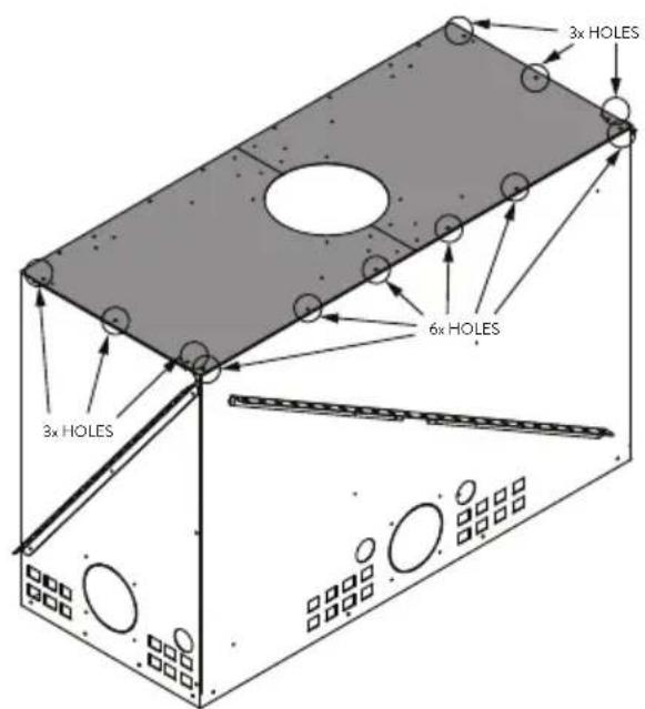
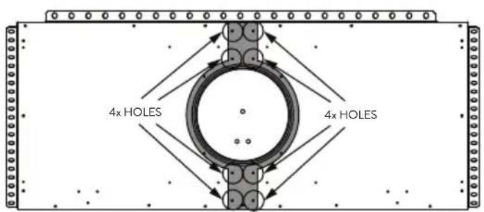

- Complete the zero clearance kit by first assembling 2x long standoff brackets to the top panels using Tek screws (1/4" size) and then attaching the two lintel standoffs to the top panels using 6x Tek screws (1/4" size). The fastening locations are circled in the diagrams below.


natural_image
Technical line drawing of a mechanical housing with mounting holes and internal components, plus an inset showing 3x Holes detail (no text or symbols)- Connect 3 pieces of the ∅250mm galvanised liners together to create a long liner pipe. Use a minimum of 3x SS rivets to connect the pipes together.
Position the ∅250mm flue liner (with the crimped end pointing upwards) over the zero clearance kit spigot. Use a minimum of 3x SS rivets to fasten the 250mm flue pipe to the zero clearance kit spigot.
Note: It is recommended to take a photo of the 250mm spigot joint after riveting. This may be required by the council inspector for sign off.
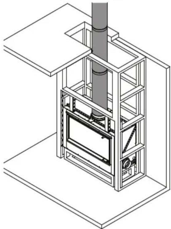
natural_image
Isometric line drawing of a mechanical device with internal components and mounting base (no text or symbols)- Assemble the Skamotec wall boards by gluing them to the fixing brackets. The Skamotec boards will need to be primed prior to gluing. Use Mapei Primer G or other suitable tile primer for this process. Use RTV high-temp silicone sealant for gluing the skamotec panels.
*Note: Skamotec dimensions will depend on which wall install scenario is specified. Refer to sections C7, C8 for more details regarding Skamotec dimensions. Please contact an Escea Architectural Advisor for any further queries regarding Skamotec installation.
It is recommended to compress the skamotec onto the fixing brackets while the glue cures. Wait for at least 24 hours for the glue to set. Make sure all joints are glued.

-
Once the skamotec is secure, glue the fibre cement sheets to the skamotec. Note: fibre cement sheet dimensions will depend on which wall install scenario is specified. Refer to sections C7, C8 for more details.
-
Install the trim assembly on to the woodfire once the fibre cement sheets are secure.
Note: the trim specified will depend on the chosen wallboard install. For a painted finish, the TC950 Linear Fascia will be fitted. For an alternative wallboard finish, the TC950 Frameless trim will be fitted. Refer to sections C7, C8 for more details.
The ash lip will need to be removed to access the screw points for the trim. Loosen the M8 barrel nuts (13mm spanner), taking care not to lose the nuts.
Use the supplied 6x Pozi screws to secure the trim at the 3x points at the top, and 3x points at the bottom of the chassis.
Resecure the ash lip to the product.
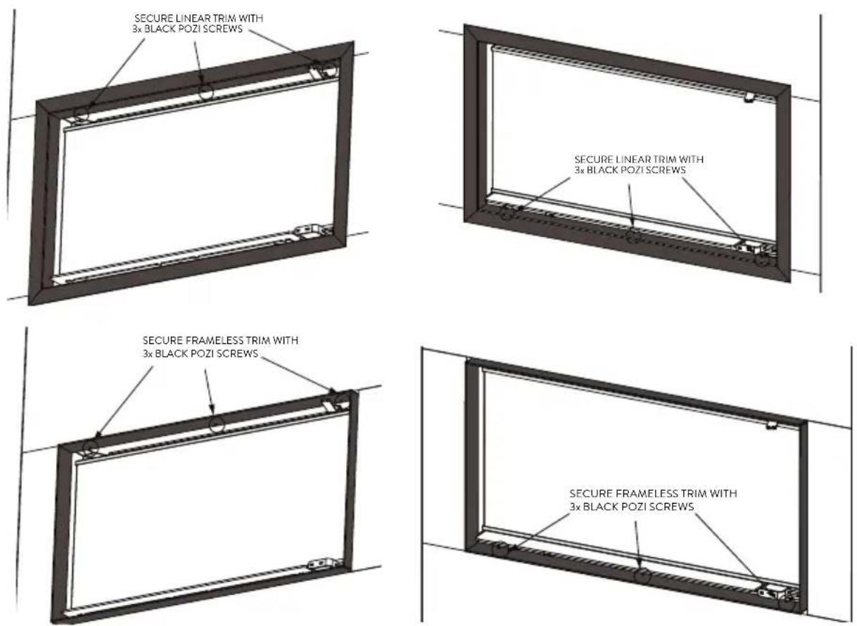
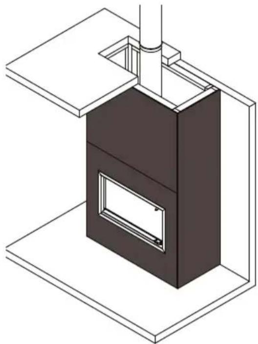
- Assemble the remaining wallboards to the sides of the enclosure. The side walls can finished with standard building materials.
The fibre cement can be plastered or finished to match the surrounding walls. Any finishing plaster/ finish should be heat resistant/ non-combustible.
natural_image
Isometric line drawing of a two-story industrial furnace or chamber with a vent, mounted on a platform (no text or symbols)- Install the vermiculite panels to the product. The door should be removed before the vermiculite panels are installed. Open the door and carefully lift it up to disengage from the door hinge. Pull the door away from the product to remove it completely.

natural_image
Technical line drawing of a mechanical assembly with no visible text or symbols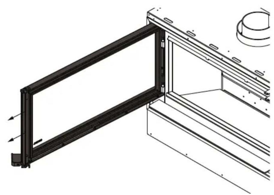
natural_image
Technical line drawing of a structural frame assembly with directional arrows indicating force or movement (no text or symbols present)- Install the back vermiculite panel by tilting the panel and placing the bottom edge of the back panel above the ember air plenum. Carefully push the top of the back panel towards the back wall of the firebox.
Note: Please refer to the diagram below for the correct orientation of the back vermiculite panel during installation to the firebox.
Note: the back panel is not self retaining, so will need to be kept in place while the side panel is prepared.

natural_image
Technical line drawings of two industrial furnace or oven units with internal compartments and mounting brackets (no text or symbols)
- Install the left and right side vermiculite panels next by placing the panels on the sides above the firebox base. Carefully push the top of the side panels towards the side walls of the firebox.
*Note: Please refer to the diagram below for the correct orientation of the side vermiculite panels during installation to the firebox.

natural_image
Technical line drawing of a mechanical enclosure or enclosure with internal components and mounting holes (no text or symbols)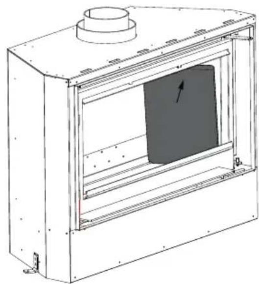
natural_image
Technical line drawing of a mechanical enclosure or enclosure with a central panel and top cylindrical component (no text or symbols)
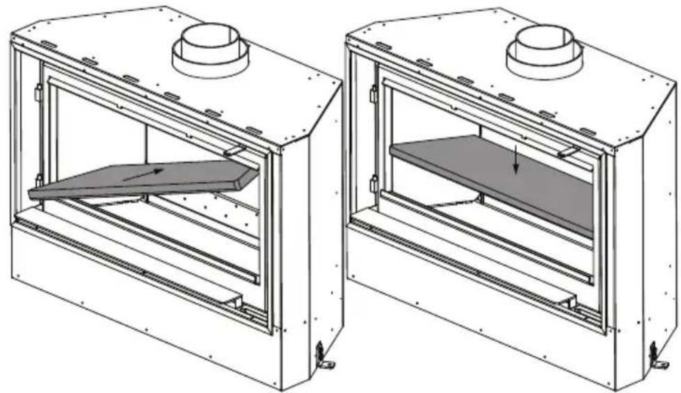
- Install the bottom vermiculite panel by placing it above the firebox base. Tilt the base panel roughly 30^ to fit the panel through the firebox opening.
The door will be re-assembled to the product after installing the bottom vermiculite panel. Re-engage the door hinge to the hinge pins to re-attach the door to the product.
*Note: Please refer to the diagram below for the correct orientation of the base vermiculite panels during installation to the firebox.
natural_image
Technical line drawing of two industrial furnace or chamber designs with internal components and mounting holes (no text or symbols)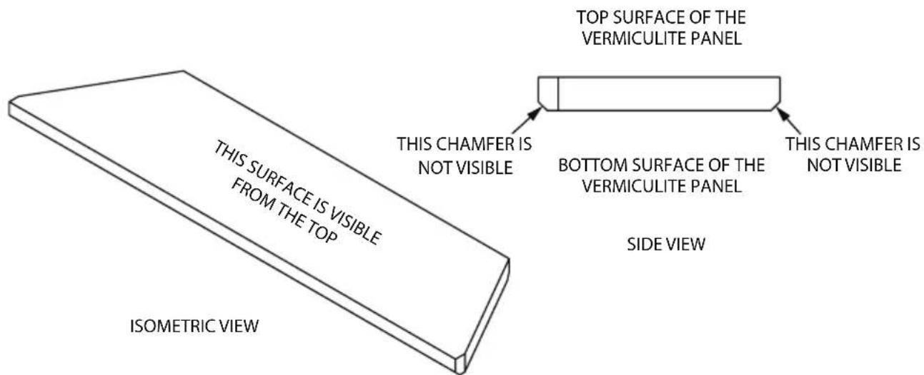
All Escea woodfires MUST be installed with the relevant Escea supplied flue kit. Additionally, the flue kit must be installed to fully meet the requirements of AS/NZS 2918:2018 Domestic solid fuel burning appliances – Installation.
Flue System Description:
The Escea TC950 flue system is unique as it draws combustion air from the same pressure zone as the exhaust gases, eliminating downdrafts and ensuring an efficient burn. It is comprised of the following:
- 150mm diameter stainless steel flue sections for the exhaust air
- 200mm diameter stainless steel flue sections for the intake air.
- 250mm diameter galvanised steel outer liner sections for zero-clearance kit venting air.
Flue Height - Minimum Requirements
The flue system is supplied with 3 lengths of 1219mm (for all flue and liner diameters) and 1x 915mm (for the ∅150mm flue). The total height of the supplied flue is 4.5m.
There MUST be a minimum of 4.5m of flue installed above the spigot. Pipes can be cut down on site to satisfy this minimum requirement.
The flue lengths above the cone MUST NOT be cut down as the 915mm length 150mm diameter section is required for the fireplace to draw effectively.
Flue Clearances
At any point above the minimum cavity height of 2400mm, a 25mm clearance between the 250mm dia liner and any combustible material MUST be maintained.
General Installation Procedure:
*Note: The total length of the connected flue pipes must be within the requirements of AS/NZS 2918:2018 Domestic solid fuel burning appliances - Installation.
Do not cut any of the flue pipes above the flue cone. For minimum flue dimensions, refer to Flue Size - Minimum Requirements section.
- Connect 3x pieces of the 1219mm long, ∅150mm flue pipes together to create a long flue pipe. Drill through the flue pipes and use a minimum of 3x stainless steel rivets per flue joint.
Place ∅150mm flue spiders around each of the ∅150mm flue pipes. Tighten the screws and nuts to secure the spiders to the flue pipes. Drill through spider and flue pipes and use a minimum of 3x stainless steel rivets to secure the spiders to the flue.
Position the long ∅150mm flue pipe (with the crimped end pointing downwards) into the appliance's inner spigot. Use a minimum of 3x stainless steel rivets to fasten the ∅150mm flue pipe to the inner spigot.
- Connect 3x pieces of the 1219mm long, ∅200mm flue pipes together to create a long flue pipe. Drill through the flue pipes and use a minimum of 3x stainless steel rivets per flue joint.
Place ∅200mm flue spiders around each of the ∅200mm flue pipes. Tighten the screws and nuts to secure the spiders to the flue pipes. Drill through spider and flue pipes and use a minimum of 3x stainless steel rivets to secure the spiders to flue.
Position the long ∅200mm flue pipe (with the crimped end pointing downwards) into the appliance's outer spigot. Use a minimum of 3x stainless steel rivets to fasten the 200mm flue pipe to the outer spigot.
- Connect 3 pieces of the 1219mm long, ∅250mm liner pipe together to create a long liner pipe. Drill through the liner pipes and use a minimum of 3x stainless steel rivets per joint. Note: the third piece of ∅250mm liner will need to be cut down such that it is flush with the ∅200mm flue pipe end when installed.
Position the long ∅250mm flue liner (with the crimped end pointing upwards) over the zero clearance kit spigot on the top panel of the zero clearance kit. Use a minimum of 3x stainless steel rivets to fasten the 250mm liner pipe to the zero clearance kit spigot.
- Install the top section of the flue kit as per the instructions below.
Escea Classic Flue Kit:
Escea's woodfire flue system is unique as it draws combustion air from the same pressure zone as the exhaust gases, eliminating downdrafts and ensuring an efficient burn.
*Note: The total length of the connected flue pipes must be within the requirements of AS/NZS 2918:2018 Domestic solid fuel burning appliances - Installation. Additionally, Escea requires a minimum of 4.5m of flue above the flue spigot.

Installation Procedure - Classic Flue Kit:
- Install partially completed flue system according to the general installation procedures.
- Place the 150mm cone spacer above the flue system and tighten the nut to hold it in place. Connect the 915mm long, 150mm diameter flue pipe to the existing long flue pipe. Drill through and rivet through the spacer and flue pipes using a minimum of 3x stainless steel rivets.

natural_image
Two cylindrical electronic components with mounting flanges, one upright and one vertical (no text or symbols)- Assemble the cone to the 150mm diameter flue pipe. Assemble the cowl to the 150mm diameter flue pipe. Drill through and rivet through the cone pipe, cowl and flue pipe using a minimum of 3x stainless steel rivets.
*Note: Necessary for water tightness, ensure a good mechanical seal is present when the cowl and cone pipe are connected to the flue pipe. This process may require 6x rivets to accomplish a good mechanical seal.

natural_image
Two 3D-rendered electronic components with cylindrical pins, one dark and one light, shown without any text or symbols.Optional Accessory- Escea Designer Flue Shroud:
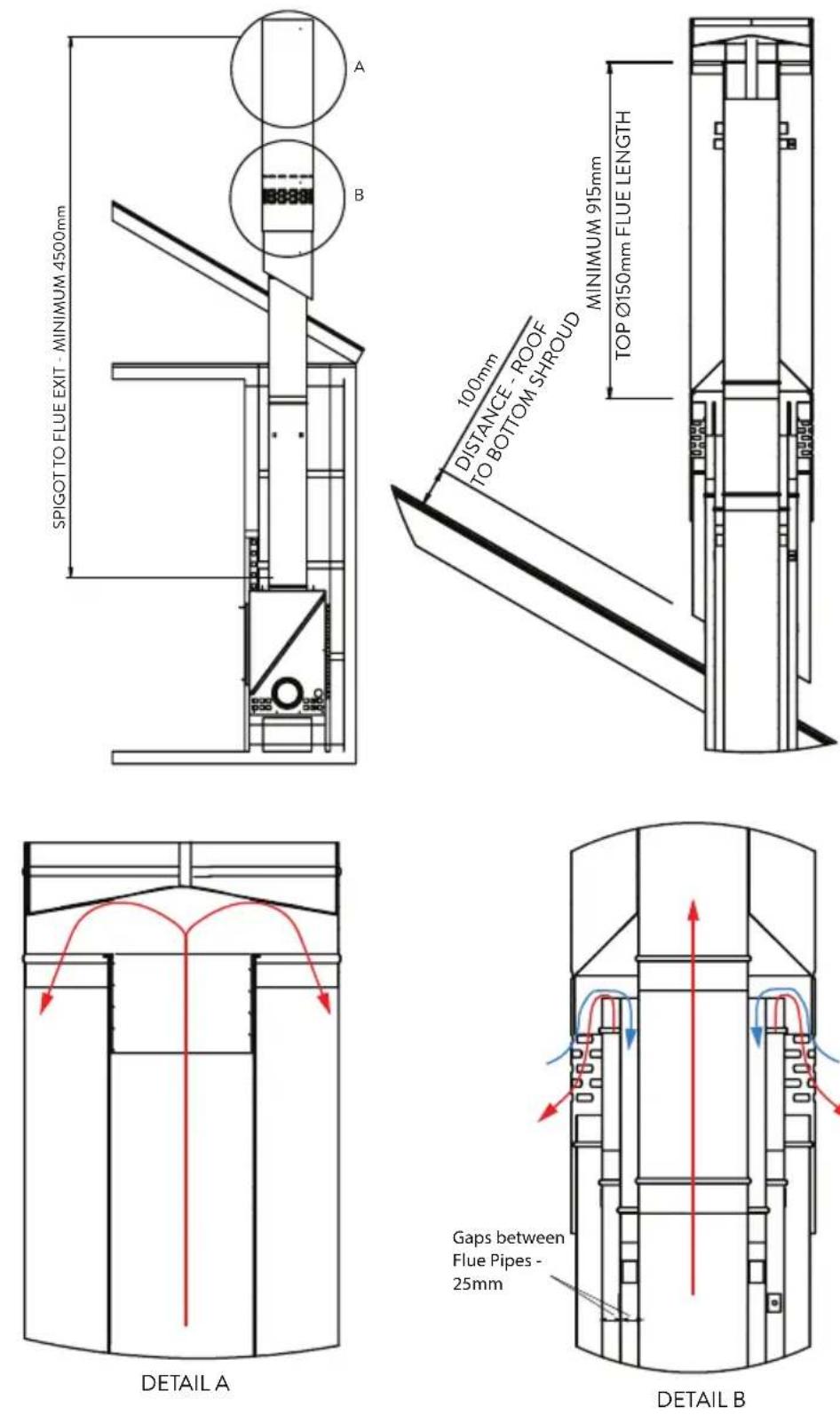
A minimalist shroud can be purchased as an optional accessory to the Escea flue kit, providing a sleek design solution.
*Note: The total length of the connected flue pipes must be within the requirements of AS/NZS 2918:2018 Domestic solid fuel burning appliances - Installation. Additionally, Escea requires a minimum of 4.5m of flue above the flue spigot.
Installation Procedure - Escea Designer Flue Kit:
-
Install the Escea Classic Flue Kit as per the above instructions.
-
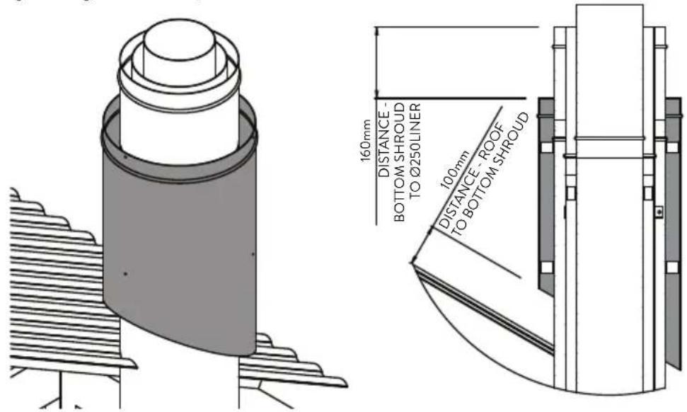
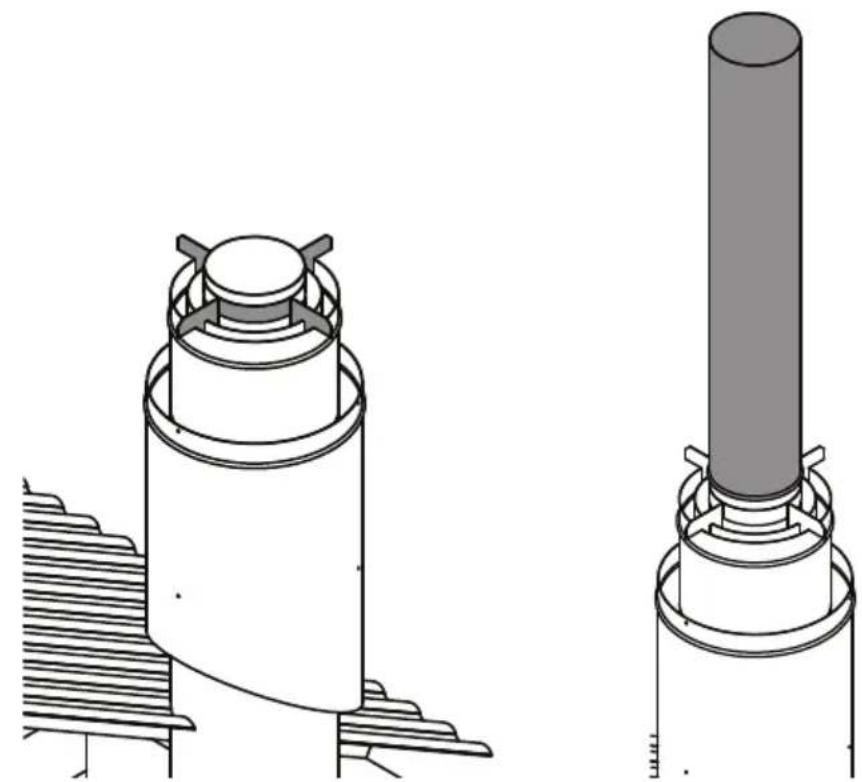
Cut the bottom shroud from the non-crimped end to be above by 100mm from the roof line. Be aware of the roof pitch when cutting the bottom shroud. If required, a cutting template for the flue is provided showing common roof pitches.
Note: The bottom shroud will be below the top end of the ∅250mm flue liner by 160mm; this distance must be considered when cutting the Bottom Shroud.

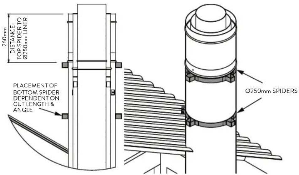
- Place 2x ∅250 spiders on the ∅250mm flue liner which will align the top and the bottom of the bottom shroud to the main flue assembly. The top spider must be at least 260mm lower than top edge of the ∅250mm flue liner. The position of the bottom spider will be dependent on the cut length of the bottom.
Tighten the screws and nuts to secure the spiders to the flue liners. Drill through spider and flue pipes and use 3x of the provided SS rivets to further secure the spiders to flue.
E
- Place the bottom shroud around the flue system, on the ∅250 spiders. Position the bottom shroud below the top end of the ∅250mm flue liner by 160mm, as mentioned in Step 2.
Drill through the legs of the ∅250 spiders and secure the bottom shroud to these spider legs using 4x of the provided SS rivets.
- Place the 150mm cone spacer above the flue system. Connect the 915mm long, 150mm diameter flue pipe to the existing long flue pipe. Drill through flue pipes and use the provided rivets to connect flue pipes together.
natural_image
Technical line drawing of two mechanical components with no visible text or symbols- Assemble the cone pipe assembly to the 150mm diameter flue pipe. Assemble the cowl to the 150mm diameter flue pipe. Drill through and rivet through the cone pipe, cowl and flue pipe using 3x of the provided SS rivets.
*Note: Necessary for water tightness, ensure a good mechanical seal is present when the cowl and cone pipe are connected to the flue pipe. This process may require 6x rivets to accomplish a good mechanical seal.

natural_image
Two 3D mechanical components with cylindrical bases, one gray and one white, shown from different angles (no text or symbols)- Slide the top shroud over the flue system. Secure the top shroud to the cowl and to the cone pipe assembly. Drill through and rivet through the cone pipe, cowl and top shroud using 3x of the provided SS rivets.
*Note: Ensure that the at least five rows of the top shroud air slots are not blocked by the cone.

Flue Restraints:
The flue above the roof must be restrained as per AS/NZS 2918:2018 Section 4.10 - Fixing
Flue Flashing:
The rubber flashing, flashing plate and other flashing material used must comply with the relevant building code/ local building regulations. Silicone flashing is the recommended flashing material for both Classic and Designer flue kits.


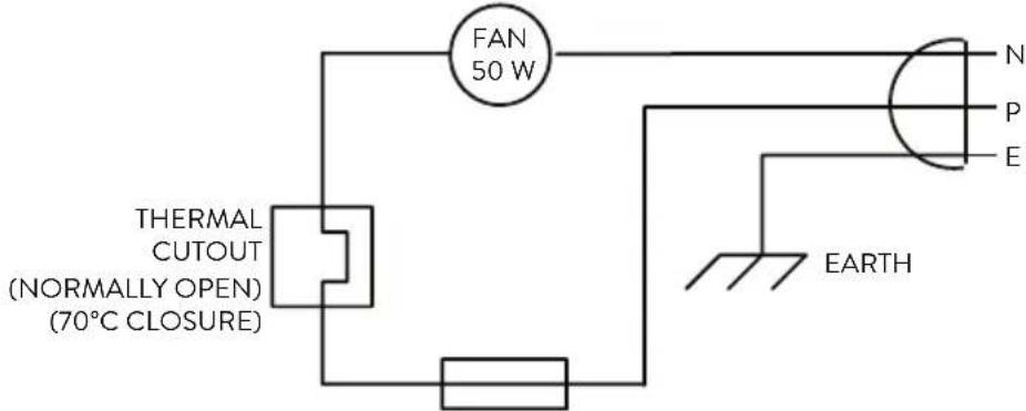
E1 Electrical Information
The TC950 will be connected to mains power. The woodfire would be left switched on at all times. The product has a thermal switch that will trigger at an optimal temperature to turn the fan on.
*Note: The fan will turn off once the woodfire has sufficiently cooled down.
WRIG
ITIM DTRYT HVEP WERT THE F T TIME
The wiring diagram for the fan is provided below.
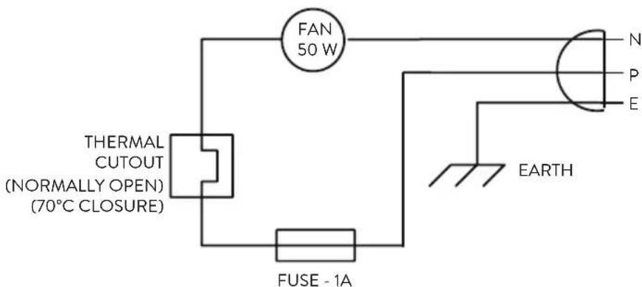
Ensure that there is always a socket installed within 1 meter of the product that is accessible after installation. Ensure that an isolation switch is hard-wired to the wall.
Escea will supply a replacement supply cord if the supply cord is damaged. An Escea service agent or a similarly qualified person will conduct maintenance of the supply cord to avoid any hazards.
WARNING
DO NOT MODIFY THIS APPLIANCE.
BURN WELL SEASONED WOOD ONLY (LESS THAN 25% MOISTURE).
ALWAYS OPERATE THIS APPLIANCE WITH THE DOOR CLOSED AND LATCHED EXCEPT DURING START UP AND RE-FUELING.
ALWAYS WEAR GLOVES TO PREVENT INJURY.
DO NOT LEAVE THE FIRE UNATTENDED WHEN THE DOOR IS UNLATCHED OR WHEN USING A SPARK SCREEN AS UNSTABLE WOOD COULD FALL OUT OF THE FIRE CHAMBER CREATING A FIRE HAZARD TO YOUR HOME.
NEVER EVER, NOT EVEN FOR A BRIEF MOMENT, LEAVE CHILDREN UNATTENDED WHEN THERE IS A FIRE BURNING IN THE APPLIANCE.
NEVER USE GASOLINE, GASOLINE-TYPE LANTERN FUEL, KEROSENE, CHARCOAL LIGHTER FLUID, OR SIMILAR LIQUIDS TO START OR 'FRESHEN UP' A FIRE IN THIS APPLIANCE.
KEEP ALL SUCH LIQUIDS WELL AWAY FROM THE APPLIANCE WHILE IT IS IN USE.
OBJECTS PLACED IN FRONT OF THE APPLIANCE SHOULD MAINTAIN A SAFE DISTANCE.
OPEN AIR CONTROL (AND DAMPER WHEN FITTED) BEFORE OPENING FIRING DOOR.
HOT WHILE IN OPERATION: KEEP CHILDREN, CLOTHING AND FURNITURE AWAY.
WARNING
DO NOT OPERATE YOUR APPLIANCE WITH THE DOOR OPEN OR AJAR.
ONLY OPEN THE DOOR WHEN FUELING/REFUELING YOUR APPLIANCE.
WEAR SUITABLE GLOVES TO OPERATE YOUR APPLIANCE.
NEVER OPERATE THE STOVE WITH THE GRATE COVER REMOVED.
DO NOT POKE OR STIR THE LOGS WHILE THEY ARE BURNING.
AVOID RISK OF BURNS. REMOVE OPERATIONAL TOOL AFTER USE!!!
BRIEF CONTACT MAY CAUSE SKIN BURNS.
F1 First Fires
The first fire(s) in your appliance may be difficult to get going and keep going with a lesser amount of heat being generated. This is a result of the moisture being driven out of the vermiculite panels. Allow several hours of hot fires before your appliance will perform optimally.
During the break-in period (the first 2 or 3 fires) create only small, hot fires using kindling or small wood pieces. Do not be alarmed if small hairline cracks develop in the vermiculite and some painted parts may also produce a smell. These are normal occurrences and do not pose safety hazards.
F2 Recommended Methods of Lighting a Fire
Traditional Method of Lighting a Fire (Bottom Up):
To start, a brisk fire is required. Place loosely crumpled paper on the floor of the appliance and cover with dry kindling. Fully open the flue damper by moving the handle to the right. Light the paper and close the door. Alternatives to paper such as firelighters can also be used to light the fire.
To maintain a brisk fire, a hot ember bed must be established and maintained.
Slowly add slightly larger wood pieces. Lay the pieces lengthwise from front to back in the hot ember bed with a small gap between each piece so that the air can flow directly into this gap and ignite the fuel above.
When the fire seems to be at its peak, medium/ large sized logs may be added. Close the door immediately after refueling to avoid drawing room air into the firebox.
WARNING
As soon as the door is closed, you will observe a change in the flame pattern due to room air not getting into the firebox. The flames will get smaller and lazier as result because less oxygen
is getting into the combustion chamber.
The flames will remain lazy but become larger again as soon as the firebox has been heated thoroughly and the flue system becomes heated and provides a good draft. At this point, the roaring fire that you see when the door is opened is wastefully drawing heated room air up the flue; this is not desirable.
You can now add larger pieces of wood and operate the appliance normally. Once the appliance is entirely hot, it will burn very efficiently with little smoke from the flue. There will be a bed of orange embers in the firebox.
You can safely fill the firebox with wood up to 50%.
Once the medium sized firewood is burning briskly and an ember bed has started to establish you can control the fire adjusting the flue damper handle.
Sliding the control to the left will reduce the air and result in a slower burning and less intense fire/heat. Sliding the control to the right will result in more air and a quicker burn with more intense fire/heat.
Learning to manage the appliance to your liking requires some practice, as you must first become familiar with its functioning. Do not expect an
F
immediate reaction of the fire when you adjust the air control. The flame will not intensify or diminish quickly as is the case with liquid or gas fuels. Solid fuels like firewood react more slowly.
Top – Down Lighting Method (Alternative)
Lighting a fire can sometimes be difficult. The following method of lighting a fire is one that is widely practiced in other parts of the world. This is a tried and tested procedure which is better for the environment.
If you experience problems with the traditional (bottom up) method, particularly relating to smoke spillage then please try the following:
People often talk about top down and bottom up lighting. You either start lighting from the top or from the bottom. The top down method produces less soot and ashes (better for the environment), minimises smoke spillage into the room, ensures better air supply and makes the first wood load last longer.
What you will need:
- 3 or 4 larger logs of wood (dry)
- 8 to 12 pieces of kindling sticks
- Firelighters
- Matches
Step 1:
- Ensure that all air control in the fireplace is fully open (if available). Put the logs on the bottom of the fireplace. It is important that the wood is cleft and dry. The logs may be as thick as a fist or thicker.
Step 2:
- Add a layer of small logs of about 4 cm, and then one or two layers of kindling. Remember that air is important – approx. 1 cm between the pieces of wood is the perfect spacing.
Step 3:
- Put 3 or 4 pieces of paraffin or alcohol based firelighter (about 3cm x 3cm each) on top of the layer of kindling wood.
Step 4:
Light each of the firelighter pieces and close the door. Wait for when the flames are well established and the larger logs are burning.
After the initial burn, add required amount of wood and adjust the flue damper handle to the desired position.
DO NOT OVERFIRE THE APPLIANCE!
Overfiring can occur by:
A. Burning large amounts of smaller wood pieces such as furniture scraps or skids.
B. Overfilling your appliance. Load wood only up to 50% of the firebox height.
C. Operating the appliance with a poor gasket seal on the main door.
D. Burning the fire with the door open.
WARNING
DO NOT BURN TREATED WOOD!
Expansion / contraction noises during heating up and cooling down cycles are normal and to be expected.
After extended periods of non-operation such as following a vacation or a warm weather season, the appliance may emit a slight odor for a few hours. This is caused by dust particles on the firebox burning off. Open a window to sufficiently ventilate the room.
Can't get the fire going?
Use more kindling and paper (or firelighters). Assuming the chimney and vent are sized correctly and there is sufficient combustion air, the lack of sufficiently dry quantities of small kindling may be the problem. Thumb size is a good gauge for small kindling diameter.
Can't get heat out of the appliance?
One of two things may have happened. The appliance itself has not reached optimum temperature or the flue damper is positioned all
the way to the left.
Slide the air control fully to the right for quicker burn and a more intense fire.
Another problem may be wet or green wood. The typical symptom is sizzling wood and moisture being driven from the wood.
DO NOT STORE FUEL WITHIN THE CLEARANCE TO COMBUSTIBLES ZONE, OR IN THE SPACE REQUIRED FOR RE-FUELING AND ASH REMOVAL.
F3 Fuel Information
WARNING
THIS APPLIANCE IS DESIGNED TO BURN NATURAL HARDWOOD (AUSTRALIA) WITH A MOISTURE CONTENT OF LESS THAN 25% ONLY - YOU CAN USE THE MOISTURE METER PROVIDED ALONG WITH THE WOODFIRE PRODUCT.
DO NOT BURN TREATED WOOD, COAL, CHARCOAL, COLOURED PAPER, CARDBOARD, SOLVENTS OR GARBAGE.
HIGHER EFFICIENCIES AND LOWER EMISSIONS GENERALLY RESULT WHEN BURNING AIR DRIED SEASONED WOOD, AS COMPARED TO GREEN OR FRESHLY CUT WOOD.
DO NOT BURN GREEN OR FRESHLY CUT WOOD.
BURNING WET UNSEASONED WOOD CAN CAUSE EXCESSIVE CREOSOTE ACCUMULATION. WHEN IGNITED IT CAN CAUSE A CHIMNEY FIRE THAT MAY RESULT IN A SERIOUS HOUSE FIRE.
DO NOT STORE FUEL WITHIN THE SPACE REQUIRED FOR RE-FUELING AND ASH REMOVAL.
When loading the appliance, ensure that the air bar is not forced out of position. For maximum efficiency, when the appliance is thoroughly hot, load it to 50% of the firebox height and burn at a medium-low setting. The cleanliness of the glass are good indicators of your operating efficiency. Not enough heat is produced when only a few pieces of wood are burned or the wood may not burn completely.
NOTE: When loading the appliance, ensure to keep fuel back from the glass. If fuel is allowed to accumulate on the front lip, there is a chance it will fall out when the door is opened.
Burn only dry, clean unpainted wood that has been seasoned. It produces more heat and less soot or creosote. Freshly cut wood contains about 50% moisture while after proper
F
seasoning only about 20% of the water remains. As wood is burned, this water boils off, consuming energy that should be used in heating. The wetter the wood, the less heat is given off and the more creosote is produced. Dry firewood has cracks in the end of the grain.
Firewood should be split, stacked in a manner that air can get to all parts of it and covered in early spring to be ready for burning the following autumn.
Cut the wood so that it will fit horizontally side to side.
F4 Smoke Information
A properly installed appliance should not smoke. If yours does, check the following:
- Has the flue had time to get hot?
- Is the smoke passage blocked anywhere in the appliance, flue connector or flue system?
- Is the smoke flow impeded by too long a horizontal pipe or too many bends?
- Is it a weak draft perhaps caused by a leaky flue, a cold flue, a flue system that is too short, or a flue system that is too close to trees or a higher roof?
F5 Ash Removal Procedures
WARNING
IMPROPER DISPOSAL OF ASHES MAY RESULT IN FIRES.
DO NOT DISCARD ASHES IN CARDBOARD BOXES, DISCARD IN BACK YARDS, OR STORE IN GARAGES.
IF USING A VACUUM TO CLEAN UP ASHES, BE SURE THE ASHES ARE ENTIRELY COOLED. USING A VACUUM TO CLEAN UP WARM ASHES COULD CAUSE A FIRE INSIDE THE VACUUM.
NEVER OPERATE YOUR APPLIANCE WITH THE ASH PLUG (IF APPLICABLE) REMOVED.
FAILURE TO ACHIEVE A GOOD SEAL BETWEEN THE ASH OPENING, ASH PLUG OR ASH WELL DOOR MAY RESULT IN AN OVER FIRE CONDITION THAT COULD CAUSE DAMAGE TO THE APPLIANCE AND/OR SURROUNDINGS.
Allow the ashes in your firebox to accumulate to a depth of 50 - 75mm; they tend to burn themselves up.
When the fire has burned down and cooled, remove any excess ashes but leave an ash bed approximately 25mm deep on the firebox bottom to help maintain a hot charcoal bed.
Shovel some ashes out through the door into a metal container with a tight fitting lid. Keep the closed container on a non-combustible floor or ground, well away from all combustible materials. The ashes should be retained in the closed container until all cinders have thoroughly cooled. Cold wood ashes can be used on the garden or in compost.
F6 Creosote Formation and Removal
When wood is burned slowly, it produces tar and other organic vapors, which combine with expelled moisture to form creosote. The creosote vapors condense in the relatively cooler flue of a slow-burning fire. As a result, creosote residue accumulates on the flue lining. When ignited this creosote makes an extremely hot fire. The chimney connector and chimney should be inspected regularly during the heating season to determine if a creosote build-up has occurred. If creosote has accumulated it should be removed to reduce the risk of a chimney fire.
WARNING
A CHIMNEY FIRE CAN PERMANENTLY DAMAGE YOUR FLUE SYSTEM.
THIS DAMAGE CAN ONLY BE REPAIRED BY REPLACING THE DAMAGED COMPONENT PARTS. CHIMNEY FIRES ARE NOT COVERED BY THE WARRANTY.
CAUSES:
- Using incorrect fuel, or small fuel pieces which would normally be used as kindling.
- Leaving the door ajar too long and creating extreme temperatures as the air rushes in the open door.
- Improperly installed or worn gaskets.
- Creosote build-up in the flue.
SOLUTIONS:
- Do not burn treated or processed wood, coal, charcoal, coloured paper or cardboard.
- Do not burn green or freshly cut wood.
- Be careful not to over fire the appliance by leaving the door open.
- Replace worn, dried out (inflexible) gaskets.
- Have the chimney regularly cleaned.
F
IN CASE OF A CHIMNEY FIRE:
- Have a well understood plan for evacuation and a place outside for everyone to meet. Prepare to evacuate to ensure everyone's safety.
- Close air damper on the appliance.
- Call local fire department. Have a fire extinguisher handy. Contact local
F7 Chimney Cleaning
Both the flue system and the appliance must be inspected and cleaned at least once a year.
For serious wood burners, chimney cleaning must be done as needed to avoid chimney fires; the venting systems for controlled combustion appliances may need cleaning more often than required. These rates, however, depend on the burning habits of the individual operating the appliance. For example, it is possible to clog a solid fuel appliance flue in a few days if slow, smouldering fires are burned and the chimney is cold.
NOTE: Appliances burned consistently without hot fires may result in significant creosote accumulations in the flue.
authorities for further information on how to handle a chimney fire.
- After the chimney fire is out, clean and inspect the flue system for stress and cracks prior to lighting another fire. Also check combustibles around the flue system and the roof.
Certain items and considerations are important in cleaning a flue:
- We recommend that you use a registered flue cleaning professional.
- Proper tools should be used, including a brush specifically designed for flue cleaning.
- The flue connector and dampers as well as the flue should be cleaned.
- The appliance's firebox and baffle system should be cleaned if needed.
- The flue system should be inspected and repairs made if needed.
- The flue should be swept from below. Removal of the vermiculite panels and air baffle from within the box is required to access flue for cleaning.
F8 Summary - Do's and Dont's
DO
- Build a hot fire.
- Use only dry wood.
- Several pieces of medium sized wood are better than a few big pieces.
- Refuel frequently using medium sized wood.
- Clean flue regularly (at least once a year).
- "Fine Tune" the air settings (if available) for optimum performance.
DON'T
- Take ash out immediately. Let it accumulate to a depth of at least one inch. A good ash layer provides for a longer lasting and better burning fire.
- Burn wet wood.
- Leave the door open after fueling/refueling the fire.
- Burn one large log rather than two or three smaller, more reasonably sized logs.
- Burn at continually "low setting". If the glass door is constantly blackened, this means the firebox temperature is too low and energy is wasted by incomplete combustion.
WARNING
APPLIANCE MAY BE HOT. DO NOT SERVICE UNTIL APPLIANCE HAS COOLED.
DO NOT USE ABRASIVE CLEANERS.
Check your flue system for creosote and soot build up regularly until a safe frequency for cleaning is established.
If accumulation is excessive, clean both the flue system and the appliance. You may want to call a professional flue cleaner to clean them. Both have to be cleaned at least once a year or as often as necessary.
Remove the vermiculite panels and air bar and clean firebox once a year. Replace any broken vermiculite.
G1 Care and Cleaning of Glass
WARNING
HOT GLASS WILL CAUSE BURNS. DO NOT TOUCH GLASS UNTIL COOLED.
f the glass is not kept clean permanent discolouration and/or blemishes may result. Normally a hot fire will clean the glass. The most common reasons for dirty glass include: not using sufficient fuel to get the appliance thoroughly hot, using green or wet wood, or closing the draft so far that there is insufficient air for complete combustion.
If it is necessary to clean the glass, buff lightly with a clean dry cloth and non-abrasive cleaner. A scotch brite pad may also be used for any fly ash on the glass surface.
DO NOT CLEAN GLASS WHEN HOT!
Clean the glass after the first 10 hours of operation with the recommended appliance glass cleaner (supplied). Thereafter clean as required.
The glass is very strong but do not let burning fuel rest or fall against it and always close the door gently. NEVER FORCE IT SHUT!
If the glass should ever crack or break while the fire is burning, do not open the door until the fire is out and do not operate the appliance again until the glass has been replaced.
New glass is available from your authorised dealer or distributor. An up to date list of authorised dealers can be found at www.escea.com
DO NOT USE SUBSTITUTE MATERIALS.
WARNING
THE GLASS CERAMIC SHEET MAY ONLY BE CLEANED WHEN COLD (FIREPLACE INSERT NOT BURNING AND COOLED DOWN; NO HOT ASH IN THE FIRE CHAMBER).
G2 Replacement Parts
Contact your dealer for questions concerning prices and policies on replacement parts.
Normally all parts can be ordered through your authorised dealer / distributor.
An up to date list of authorised dealers can be found at www.escea.com
When ordering replacement parts always give the following information:
- Model & Serial Number of appliance
- Installation date of appliance
- Part number
- Description of part
- Finish
FOR WARRANTY REPLACEMENT PARTS, A PHOTOCOPY OF THE ORIGINAL INVOICE WILL BE REQUIRED TO HONOUR THE CLAIM.
WARNING
FAILURE TO POSITION THE PARTS IN ACCORDANCE WITH THIS MANUAL OR FAILURE TO USE ONLY
PARTS SPECIFICALLY APPROVED WITH THIS
APPLIANCE MAY RESULT IN PROPERTY DAMAGE AND/OR PERSONAL INJURY.
G3 Paint Care and Cleaning
The appliance is sprayed with Senotherm high temperature paint. If any visual parts become scratched during assembly or servicing, touch up Senotherm paint cans can be purchased from your local Escea dealer. Please ensure that ONLY Senotherm is used during touch ups.
For general cleaning, use a cloth with hot water. Do not use any detergents on the paint.
G4 Accessing the Data Label
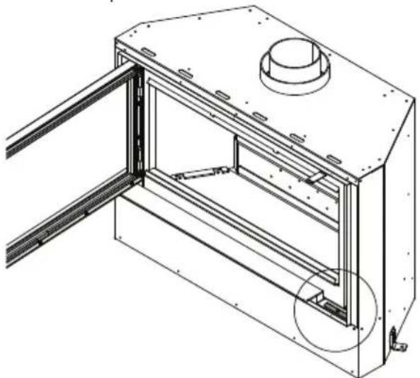
Access to the data label will be required during installation or during servicing of the product. The data label is attached on a label plate located on the ledge beneath the door (circled below). The name word "LABEL" is written on the label plate to help identify it.
The attached screw must be undone to access the label. The door must be open to locate and remove the label plate from its position.
natural_image
Technical line drawing of a mechanical assembly with no visible text or symbolsG5 Door Hinge Adjustment
To ensure continued and proper sealing, adjustments to the door and the latch bracket will be required as the seal becomes worn-out over time. Removal of the door will be required when adjusting the door.
- Open the door and lift it up to disengage from the door hinge.

natural_image
Technical line drawing of a structural frame assembly with mounting brackets and structural supports (no text or symbols)- Pull the door away from the product.

natural_image
Technical line drawing of a structural frame with mounting holes and internal supports (no text or symbols)- Undo 4x M6 nuts and 4x M6 washers (circled below) to free the hinge blocks on the left side of the product.

- Move hinge blocks inwards, towards the products, to ensure a tight seal once the door is re-attached. Re-assemble the M6 nuts and M6 washers after moving the hinge blocks.

natural_image
Technical line drawing of a door frame structure with internal components and directional arrows (no text or symbols)G6 Latch Bracket Adjustment
- Remove stud cover from the latch bracket. Unhook the stud cover from the latch bracket by pulling the stud cover up. Pull the stud cover from the latch bracket to remove it.
VIEWED FROM RIGHT SIDE OF THE PRODUCT

natural_image
Technical line drawing of a mechanical or electrical enclosure with internal components and mounting brackets (no text or symbols)WITH STUD COVER

natural_image
Technical line drawing of a mechanical or electrical enclosure with internal components and mounting features (no text or symbols)NO STUD COVER

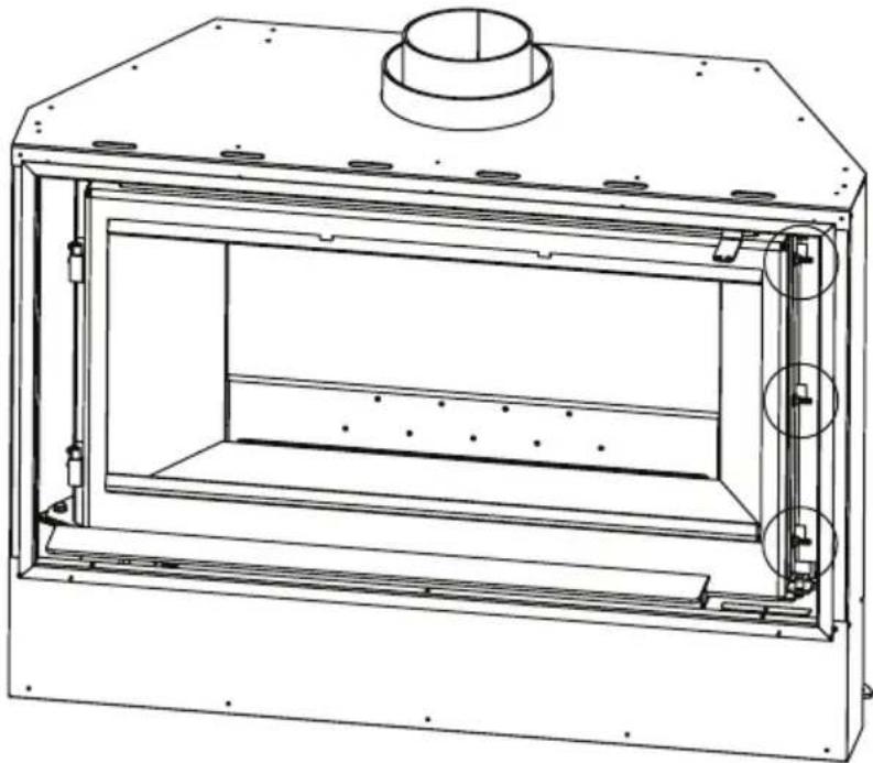
- Loosen 3x M6 nuts and 3x M6 washers (circled below) to free the latch bracket on the right side of the product.
natural_image
Technical line drawing of a mechanical enclosure or enclosure with internal components and mounting holes (no text or symbols)- Move the latch bracket inwards, towards the product, to ensure a tight seal once the door is re-attached. Tighten the bottom nut in the new latch position but leave the others loose. Re-attach the door and close the handle- this will set the new latch bracket position. Open the door and tighten the remaining M6 nuts. Close and open the door a few times to check that the latch position is stable.
Re-assemble the stud cover after setting the latch bracket position.
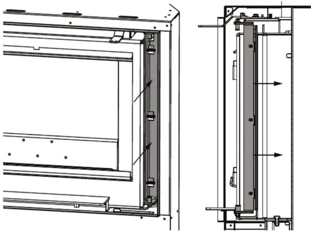
natural_image
Technical line drawing of a mechanical assembly with cross-sectional and top views (no text or symbols)G7 Door Angle Adjustment
- Loosen 4x M6 nuts and 4x M6 washers (circled below) to free the hinge adjustment plate behind the door.
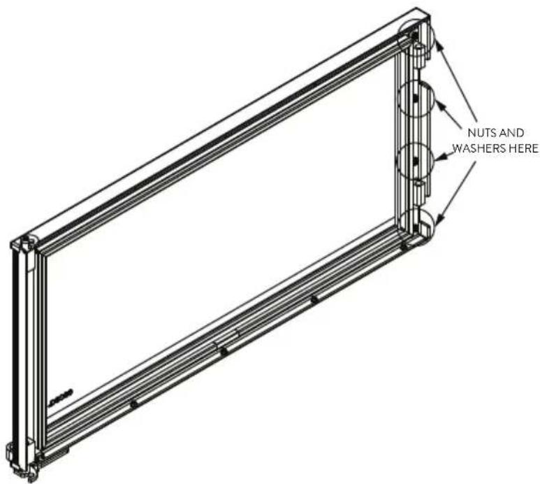
- Viewed from the back of the door, swing the top of the hinge adjustment plate to the left to adjust the angle of the door. Tighten the M6 nuts and M6 washers after moving the latch bracket.
*Note: Doing this step will shift the side of the door with the handle to upwards.

natural_image
Technical line drawing of a structural frame with mounting holes and internal ribs (no text or symbols)- Re-assemble the door once adjustments have been completed.
G8 Vermiculite Removal and Replacement
Vermiculite panels will have to be removed to gain access to the flue for cleaning and any electrical component maintenance. In the event of vermiculite panels getting damaged over time, the existing panels will also have to be removed and replaced with new panels.
The door has been removed in the diagrams below for clarity.
- Lift base panel off from the firebox by hooking one of the front corners, then tilt the base panel to roughly 30^ . Pull out one side of the panel first to remove the panel from the firebox.

natural_image
Technical line drawing of two views of a mechanical enclosure or enclosure with internal components and mounting holes (no text or symbols)- Tilt the side panel by dropping its top edge down towards the firebox base. Pull the vermiculite panel out of the firebox once angled enough for easy removal.
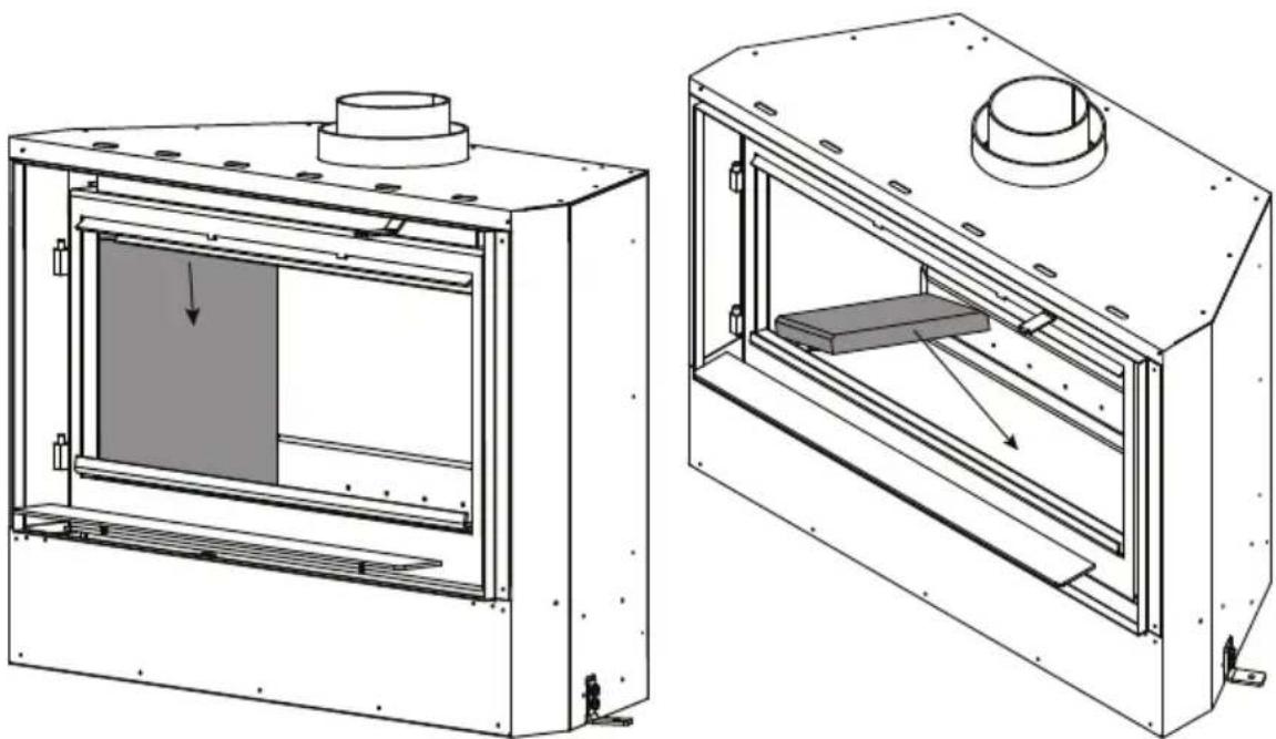
natural_image
Technical line drawings of two industrial enclosure components with internal compartments and mounting features (no text or symbols)- Repeat process for the other vermiculite panel on the other side of the firebox.
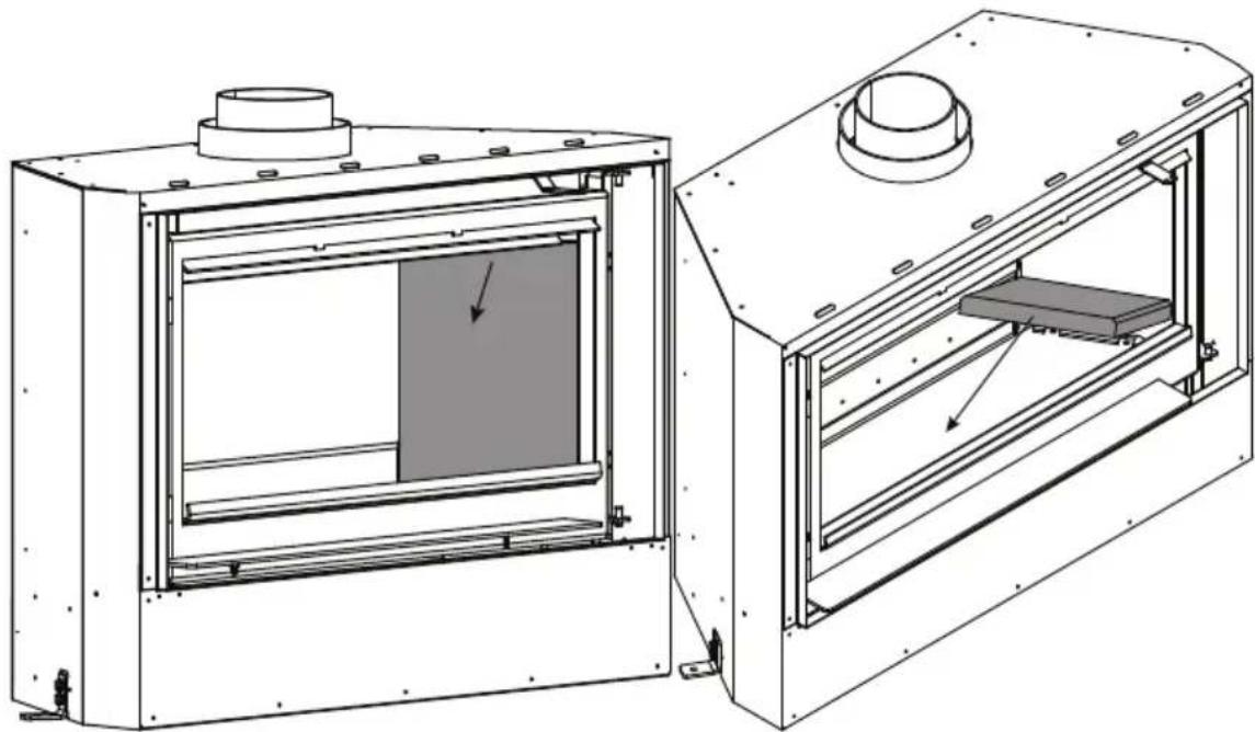
natural_image
Technical line drawing of two industrial equipment units with internal components and mounting holes (no text or symbols)- Pull down the top edge of the back panel to remove it from its position. Pull the vermiculite panel out of the firebox.

natural_image
Technical line drawings of two industrial furnace or chamber designs with internal components and directional arrows (no text or symbols)- This step is for re-installing the existing panels or replacing damaged vermiculite panels.
Place the back panel first before installing the side panels. Place the base panel last. Use the previous steps as guide for re-installing vermiculite panels. Tilt panel as required to fit the replacement panels into the firebox.
New vermiculite panels are available from your authorised dealer or distributor. An up to date list of authorised dealers can be found at www.escea.com
G9 Air Baffle Removal & Replacement
The air baffle will have to be removed to gain access to the flue for cleaning and maintenance. In the event of the baffle getting damaged over time, the baffle removal will be needed for replacement.
Ensure that the door has been removed from the product before removing the baffle.
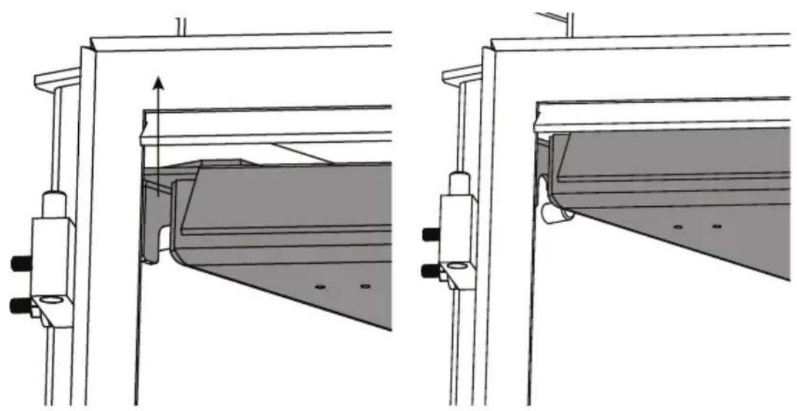
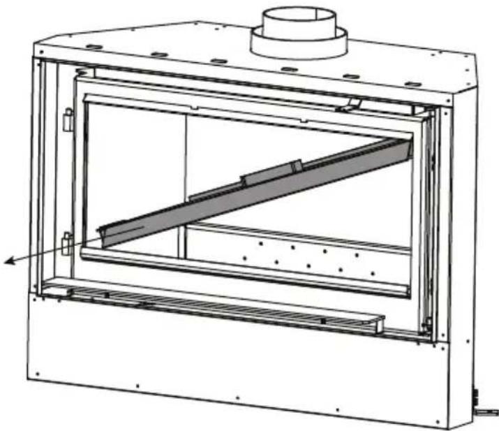
- Push the baffle up to disengage it from its holding pins. Pull the baffle forward to disengage it.
natural_image
Technical line drawing of two mechanical assembly components with mounting brackets and structural supports (no text or symbols)
natural_image
Technical line drawing of a mechanical enclosure or enclosure with internal components and mounting brackets (no text or symbols)- Drop down one side of the baffle to tilt it at roughly 30^ . Pull out one side of the baffle first to remove it from the firebox.
natural_image
Technical line drawing of a mechanical enclosure or enclosure with internal structural components (no text or symbols)- This step is for re-installing the air baffle or replacing a damaged one.
Use the previous steps as guide for re-installing the baffle. Tilt part as required to fit the replacement baffle into the firebox.
A new TC950-TFS1000 air baffle is available from your authorised dealer or distributor. An up to date list of authorised dealers can be found at www.escea.com
G10 Ash Lip Removal & Replacement
The ash lip is a customisable part which can be replaced with an ash lip of your preferred colour. The full list of of ash lip colours offered can be found at www.escea.com.
Ensure that the door has been removed from the product before removing the ash lip
- Undo 3x M8 barrel nuts (circled below) to free up the ash lip.
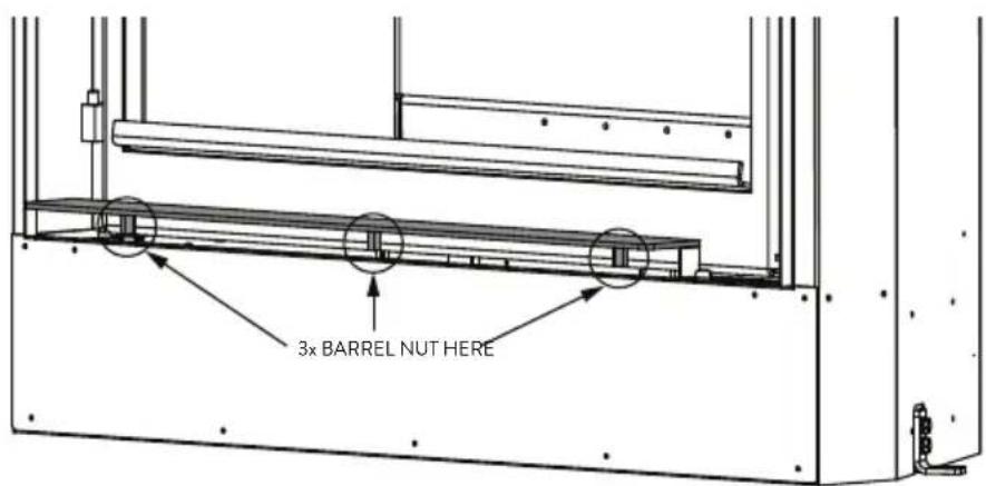
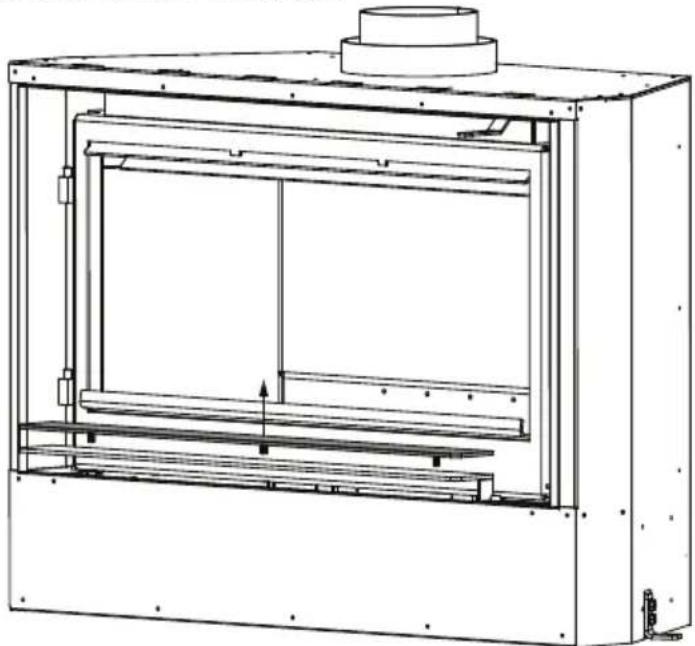
- Lift up ash lip to remove it from its holder.
natural_image
Technical line drawing of a mechanical enclosure or enclosure with internal components and mounting feet (no text or symbols)- Place the replacement ash lip on the holder to re-install on to the fireplace. Redo the 3x M8 barrel nuts to secure the ash lip to the holder.
*Note: The ash lip holder have slots that would allow you to re-adjust the ash lip forward or backward; consider the ash lip position when re-installing a replacement ash lip, depending on your preference.
New ash lips are available from your authorised dealer or distributor. An up to date list of authorised dealers can be found at www.escea.com.
G11 Maintenance of Electrical Components
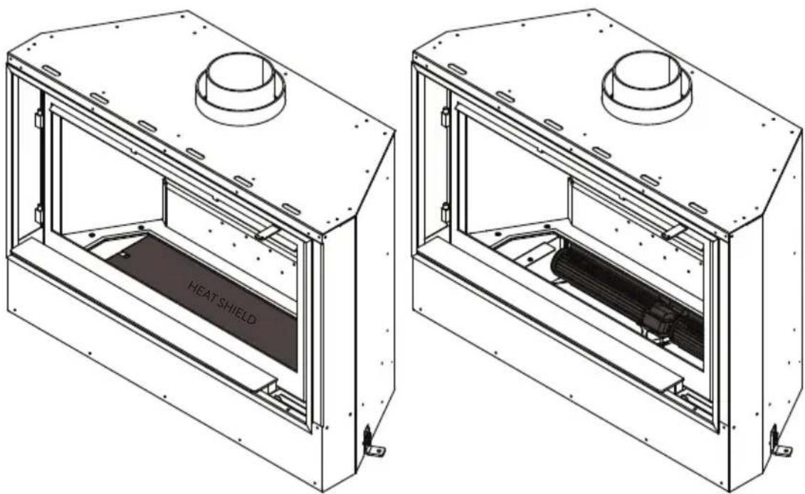
In the event of electrical components such as the fan and thermal switch becoming faulty, access will be required to conduct repairs or replacements. The following steps will detail how to access the fan & thermal switch for repairs or replacements.
Ensure that the door and vermiculite panels have been removed from the product before doing any of the following steps.
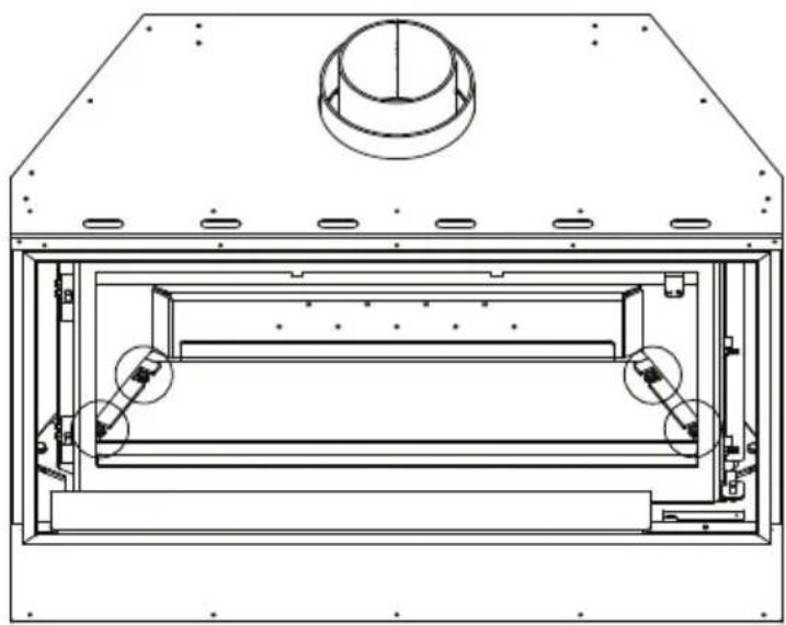
- Undo 4x M8 bolts and 4x M8 washers that fixes the ash retainer to the firebox base.
natural_image
Technical line drawing of a mechanical assembly with mounting brackets and a central circular component (no text or symbols)- Remove the ash retainer from the product. Undo 4x Tek screws (1/4" size) to remove the heat shield above the wiring and electronic components.

natural_image
Technical line drawing of a mechanical housing with internal components and mounting holes (no text or symbols)- Remove the heat shield above the wiring and electronic components. Repair or replace the required electrical component and/or wiring.
FUSE - 1A
natural_image
Technical line drawings of two industrial heat shield components with mounting flanges and internal chambers (no text or symbols)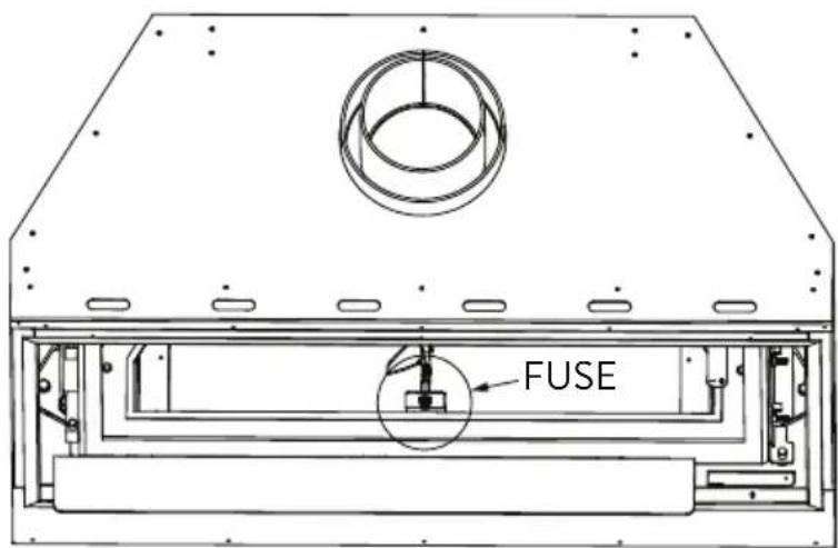
Note: the thermal cutout switch is located under the base of the firebox at the back. The fan will need to be removed to access it.
WARNING
APPLIANCE MAY BE HOT, DO NOT SERVICE
UNTIL APPLIANCE HAS COOLED.
DO NOT USE ABRASIVE CLEANERS.
| Problem Solution | |
| Can’t get the fire started. | Using firelighters? Not using enough? Add more.Not enough air? Ensure air control is fully open. Also ensure that the air opening is not obstructed.Using lots of kindling? Using softwood as kindling?Use dry seasoned wood.Flue blockage? Inspect flue system.Is the door closed? Leave door closed while kindling takes off.Use top down lighting methodIs an Escea flue system installed? Required for the fireplace to work properly. |
| Smokes when door is open. | Ensure the damper is set to high during refuelingRefrain from burning particularly smoky/ ashy wood speciesLet logs burn down to embers before opening doorLet air stabilize before opening doorInsufficient draft? Add more flue pipe. |
| Stove doesn’t burn hot enough. | Wood is too wet. Ensure moisture content is less than 20%.Insufficient draft? Add more flue pipe.Not enough air? Ensure air control is fully open. Also ensure that the air opening is not obstructed. |
| Wood burns too fast. | Air control may need to be adjusted down.Check door gasket for adequate seal (paper test). Adjust if necessary.Wood may be extremely dry eg Under 10% |
| The fire leaks through the door | Check door gasket for adequate seal (paper test). Adjust if necessary. |
| Dirty glass • Air control may be closed too far. Open air control more.Burn hotter, smaller fires. Use well-seasoned wood.Use top down lighting methodIf fly ash has accumulated over time, clean the glass | |
| Ash falls out the front | Has the wood been stacked too high? Burn big logs in one layer rather than lots of small logs in multiple layers.Refrain from burning particularly ashy wood speciesHas the ash been cleaned out recently enough? The ash will need to be cleaned out every few hours |
| The surround is scratched | Use a damp cloth to rub off scratchesUse touch up spray can of Senotherm |
General Information
This quality manufactured product is state of the art. The materials used were meticulously selected and are constantly checked, as is our entire production process.
Setting up or installing this product requires specialised knowledge. Escea products may therefore only be installed and commissioned by specialised firms and in compliance with statutory regulations as amended.
Warranty Conditions for Escea Indoor Wood Fires
This warranty is provided by the Australian Distributor of Escea Wood Fires, who trade as Escea Australia PTY Limited (referred to in this document as Escea). The warranty applies from the date of purchase from or through an authorised Escea fire dealer.
Nature of Warranty
Subject to the exclusions in section 2 & 3, Escea undertake to put right any defects in the Escea wood fire products supplied by Escea for the periods specified below:
| Parts Parts and Labour Warranty | |
| Firebox 10 years | |
| Fan and electronic components 1 year | |
| Baffle & Firebricks 1 year | |
| Door seal and glass seal 1 year |
Escea must pre-authorise all warranty work.
The benefits provided by under this warranty are in addition to the consumer guarantees and any other statutory rights you may have under the consumer law and/or other applicable laws.
Warranty Exclusions
This warranty does not apply and will be void where:
- The Escea fire is not installed in accordance with AS/NZS 2918:2018 or any building code or consent.
-
The Escea fire has not been installed or operated in accordance to the Escea installation manual, in particular, defects, malfunctions or failures caused by incorrect installation, normal wear and tear, misuse, neglect, lack of proper and regular maintenance, accidental damage or any other alteration, or failure to follow operating instructions in the installation manual.
-
The use of products, including flue systems that are not specified in accordance with installation manual.
- Repairs or modifications by persons not authorised by Escea, use of parts not supplied by Escea, or damage or other events which have occurred since the product left the control of Escea
- Any scratches, dints, fingerprint marks and melted items that occurred after the arrival of the product to the Escea Dealer.
- Improper handling of fragile components such as glass.
- Damage caused by incorrect use or the burning of inappropriate fuel. This may include treated or painted wood, coal, driftwood, high creosote wood or wood with high moisture content.
- Changes in the interior / exterior surfaces of the house, fire, or flue (e.g., any staining or soot /smoke damage or discoloration of surfaces caused by thermal stress or overload).
- Damage caused by abnormally corrosive environments (e.g. sea salt corrosion).
- Damage caused by water affecting the Escea fire.
- Operation of the Escea fire without its baffles, fire bricks, door seals, complete glass doors in place or partly open doors will create an overfired situation resulting in damage, which will not be covered by warranty.
- This warranty does not cover paint blemishes or imperfections because of the uneven nature of high temperature paint. A spray can of touch up Escea paint is available and can be purchased from your Escea dealer.
- Subject to any statutory provisions to the contrary, Escea's liability in respect of Escea products that are found to have manufacturing defects will be limited to refunding, repairing or replacing the defective products. Escea does not accept liability for consequential damage or any incidental expenses resulting directly or indirectly from any defect or breach of warranty, claims for damage to building or any other consequential loss.
- The firebox warranty shall be void if the baffle plate and air bar assembly inserted in the ceiling of the firebox is damaged in any way (including burnt out, buckled, or bowed).
- The appliance has been over-fired, over-firing can be identified by, but not limited to, warped plated or tubes, rust coloured cast iron, bubbling, cracking and discolouration of steel or paint finishes.
Other Escea Indoor Wood Fire Warranty Conditions
- No dealer, distributor, or similar person has the authority to warrant Escea products beyond the terms contained in this warranty.
- This warranty is automatically voided if the appliance's serial number has been removed or altered in anyway.
|
- Any differences in fireplace appearance from Escea promotional images that is due to printing limitations, environmental factors or wood variations are not a warranty issue.
- Where you make a claim under this warranty, an authorised repairer may need to attend your premises to inspect the Escea product. Escea may charge you a service call fee if a repairer will be required to travel more than 30 km from the nearest service centre to your location. You can obtain details on the location of service centres and service call fees by visiting the. Escea web site or calling the customer care line below
Warranty Claims
If you make a valid claim under warranty and none of the exclusions set out in section 2 and 3 apply, Escea will, at Escea's election either:
• Repair the relevant part of the Escea product; or
- Replace the relevant part of the Escea product with a product of identical specification (or where the product is superseded or no longer in stock, with a product of as close a specification as possible).
How to Make a Warranty Claim
To progress any Warranty claims for damaged appliance/parts, paint or any visual defects, photographic evidence must be supplied. Failure to provide photographic evidence may result in the claim being delayed or refused
Lodge the claim through the dealer who supplied the fire, as soon as you first become aware of the breakdown. The Escea Dealer will then follow Escea's warranty claim process.
Provide the Escea product serial number.
Provide reasonable proof of purchase for the Escea product.
If required, provide access to the premises at which the Escea product is located (so it can be inspected).
Records and receipts of chimney sweeping may be required in the event of a warranty claim if there is excessive signs of neglect or misuse.
| Escea Distributor Filing a Claim | |
| Escea Limited17 Carnforth StreetDunedin, 9018, New ZealandPh 0800 17 3000www.Escea.com | Contact the dealer you purchased the fire from. |
THIS DOCUMENT CONTAINS TECHNICAL DATA SUBJECT TO CHANGE WITHOUT NOTICE.
J1 Service History
The appliance must be serviced at least annually and possibly more frequently – deendent on usage.
| Date Dealer | Name Service | Technician Service | Performed Notes | ||
- Installation Instructions and User Guide
- WARRANTY REPAIR AND ANNUAL SERVICING
- CONTENTS
- NOTICE
- WARNING
- B1 Product Description
- B2 Specifications Table
- B3 Product Dimensions
- C1 Installation - General
- C2 Cavity Construction Requirements
- C3 Floor Protector Requirements
- C4 Mantel and Side Wall Clearances
- C5 Electrical Requirements
- C6 TV Installation Requirements
- C7 Painted Wall Finish Installation Requirements
- C8 Other Wall Finish Installation Requirements
- C9 Zero Clearance Kit Venting Requirements
- Option 1 - Venting with Outside Air (Preferred)
- Option 2- Venting with Roof Cavity Air
- Option 3- Venting with Room Air
- C10 Flue Clearances
- C11 Minimum Flue Length
- C12 External Clearances:
- C13 Floor and Wall Penetration Requirements
- Flue System Description:
- Flue Height - Minimum Requirements
- Flue Clearances
- General Installation Procedure:
- Escea Classic Flue Kit:
- Installation Procedure - Classic Flue Kit:
- Optional Accessory- Escea Designer Flue Shroud:
- Installation Procedure - Escea Designer Flue Kit:
- E
- Flue Restraints:
- Flue Flashing:
- E1 Electrical Information
- F1 First Fires
- F2 Recommended Methods of Lighting a Fire
- F
- Top – Down Lighting Method (Alternative)
- DO NOT OVERFIRE THE APPLIANCE!
- DO NOT BURN TREATED WOOD!
- Can't get the fire going?
- Can't get heat out of the appliance?
- F3 Fuel Information
- F4 Smoke Information
- F5 Ash Removal Procedures
- F6 Creosote Formation and Removal
- A CHIMNEY FIRE CAN PERMANENTLY DAMAGE YOUR FLUE SYSTEM.
- THIS DAMAGE CAN ONLY BE REPAIRED BY REPLACING THE DAMAGED COMPONENT PARTS. CHIMNEY FIRES ARE NOT COVERED BY THE WARRANTY.
- CAUSES:
- SOLUTIONS:
- IN CASE OF A CHIMNEY FIRE:
- F7 Chimney Cleaning
- F8 Summary - Do's and Dont's
- DO
- DON'T
- G1 Care and Cleaning of Glass
- DO NOT CLEAN GLASS WHEN HOT!
- DO NOT USE SUBSTITUTE MATERIALS.
- G2 Replacement Parts
- G3 Paint Care and Cleaning
- G4 Accessing the Data Label
- G5 Door Hinge Adjustment
- G6 Latch Bracket Adjustment
- G7 Door Angle Adjustment
- G8 Vermiculite Removal and Replacement
- G9 Air Baffle Removal & Replacement
- G10 Ash Lip Removal & Replacement
- G11 Maintenance of Electrical Components
- General Information
- Warranty Conditions for Escea Indoor Wood Fires
- Nature of Warranty
- Warranty Exclusions
- This warranty does not apply and will be void where:
- Other Escea Indoor Wood Fire Warranty Conditions
- |
- Warranty Claims
- How to Make a Warranty Claim
- J1 Service History
Brand : Escea
Model : TC950
Category : Heating