
M38COD - Oven Magic Chef - Free user manual and instructions
Find the device manual for free M38COD Magic Chef in PDF.

| Product Type | Electric Oven |
| Model | M38COD |
| Brand | Magic Chef |
| Dimensions (H x W x D) | 29.5 x 30 x 24 inches |
| Oven Capacity | 5.0 cubic feet |
| Weight | 105 lbs |
| Power Source | 240V / 40A dedicated circuit |
| Cooking Functions | Bake, Broil, Convection Bake, Convection Roast, Keep Warm, Self-Cleaning |
| Temperature Range | 170°F - 550°F |
| Control Type | Digital touch panel with knob |
| Door Type | Self-cleaning, removable, triple-pane glass |
| Interior Light | Yes, replaceable |
| Rack Positions | 6 positions |
| Finish | Stainless steel |
| Cleaning | Self-cleaning cycle with vapor assist |
| Safety Features | Child lock, auto shut-off, overheat protection |
| Warranty | 1 year parts and labor |
| Included Accessories | 2 flat racks, 1 broiler pan |
| Repairability | Spare parts available online; authorized service centers |
Frequently Asked Questions - M38COD Magic Chef
User questions about M38COD Magic Chef
0 question about this device. Answer the ones you know or ask your own.
Ask a new question about this device
Download the instructions for your Oven in PDF format for free! Find your manual M38COD - Magic Chef and take your electronic device back in hand. On this page are published all the documents necessary for the use of your device. M38COD by Magic Chef.
USER MANUAL M38COD Magic Chef
Commercial Gas Convection Oven
User's Manual
natural_image
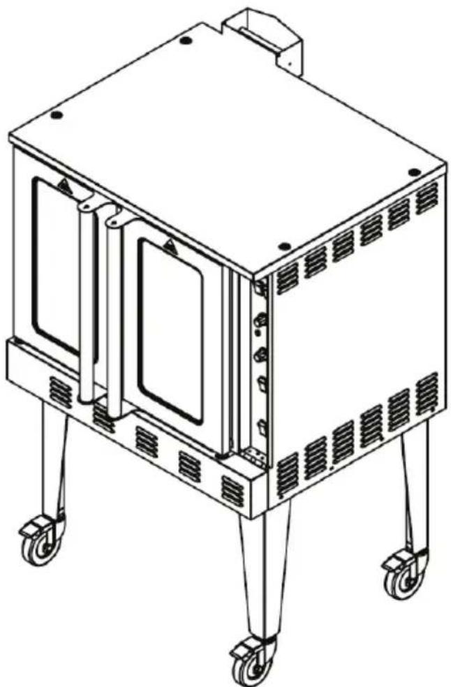
Line drawing of a four-legged industrial machine with wheels and ventilation slots (no text or symbols)Model M38COD
PLEASE READ THIS MANUAL CAREFULLY BEFORE USING YOUR COMMERCIAL STOCKPOT RANGE AND KEEP IT FOR FUTURE REFERENCE.

Magic Chef®
COMMERCIAL
PRODUCT REGISTRATION
Thank you for purchasing a Magic Chef Commercial product. The first step to protect your new product is to complete the product registration on our website: www.mcappliance.com/register. The benefits of registering your product include the following:
- Registering your product will allow us to contact you regarding a safety notification or product update.
- Registering your product will allow for more efficient warranty service processing when warranty service is required.
- Registering your product could act as your proof of purchase in the event of insurance loss.
Once again, thank you for purchasing a Magic Chef Commercial product.
CONTENTS
PRODUCT REGISTRATION 2
PRECAUTIONS 4
IMPORTANT SAFETY INSTRUCTIONS 5
SPECIFICATIONS....7
INSTALLATION INSTRUCTIONS 8
OPERATING INSTRUCTIONS.... 10
CARE AND MAINTENANCE....11
TROUBLESHOOTING 12
LIMITED WARRANTY 13
PRECAUTIONS
EXPLANATION OF SYMBOLS
WARNING
Hazards or unsafe practices which COULD result in severe personal injury or death.
CAUTION
Hazards or unsafe practices which COULD result in minor personal injury or property damage.
⚠ WARNING: Read and understand all safety precautions. Failure to follow all instructions described in this user manual may result in electric shock, fire and/or serious personal injury. The warnings, cautions and instructions discussed in this user manual cannot cover all possible conditions and situations that may occur.
⚠ WARNING: If information in this manual is not followed exactly, a fire or explosion may result causing property damage, personal injury or death. DO NOT store or use gasoline or other flammable vapors and liquids in the vicinity of this or any other appliance.
WARNING: Gas Leak
• Gas leaks cannot always be detected by smell.
• Gas suppliers recommend that you use a gas detector approved by UL or CSA.
• For more information, contact your gas supplier.
- If a gas leak is detected, follow the “What to Do If You Smell Gas” section below.
⚠ WARNING: What to Do If You Smell Gas
• DO NOT try to turn on any appliance.
• DO NOT touch any electrical switch.
• DO NOT use any phones in home.
- Immediately call your gas supplier from a phone outside of the building. (Ex: Go to a neighbor's to call your gas supplier or fire department.)
- If the gas supplier cannot be reached, call the fire department.
• Installation and service must be performed by a qualified installer or service agency.
IMPORTANT SAFETY INSTRUCTIONS
WARNING
Hazards or unsafe practices which COULD result in severe personal injury or death.
CAUTION
Hazards or unsafe practices which COULD result in minor personal injury or property damage.
IMPORTANT
In the event a gas odor is detected, shut down units at main shutoff valve and contact the local gas company or gas supplier for service.
FOR YOUR SAFETY
Do not store or use gasoline or other flammable vapors or liquids in the vicinity of this or any other appliance.
WARNING
Improper installation, adjustment, alteration, service or maintenance can cause property damage, injury or death. Read the installation, operating and maintenance instructions thoroughly before installing or servicing this equipment. In the event of a power failure, do not attempt to operate this device.
- DO NOT store or use gasoline or other flammable vapors or liquids in the vicinity of this or any other equipment.
- DO NOT use for other than intended purpose.
- DO NOT use outdoors.
- Improper installation, adjustment, alteration, service or maintenance can cause property damage, injury or death.
- Read the installation and maintenance instructions thoroughly before installing or servicing this equipment.
- Have the equipment installed by a qualified installer in accordance with all federal, state and local codes.
- DO NOT install or use without all 4 legs.
- This equipment is for use in non-combustible locations only.
- Keep the area around the appliance free and clear from combustibles.
- DO NOT obstruct the flow of combustion and ventilation air.
- DO NOT spray controls or the outside of the equipment with liquids or cleaning agents
- Allow for hot parts to cool before cleaning or moving. DO NOT touch hot surfaces.
- This equipment should only be used in a firm, dry and level surface.
- DO NOT operate unattended.
- Any loose dirt or metal particles that are allowed to enter the gas lines on this equipment will damage the valve and affect its operation.
- If you smell gas, follow the instructions provided by the gas supplier. DO NOT touch any electrical switch; DO NOT try to light the burner; DO NOT use a telephone within close proximity.
- Never attempt to move the grates while cooking.
- ALWAYS supervise the appliance while being used and never let it run while empty.
- Use only accessories recommended by the manufacturer.
- After use, some surfaces may remain hot for some time (residual heat). DO NOT rest your hands on them or allow children to get too close.
-
ALWAYS follow the correct usage procedures or the appliance may not perform properly or the user may be placed at risk.
-
The appliance is strictly for professional use and must be used by qualified personnel.
- The installation, start-up and maintenance of the appliance must be carried out by qualified personnel.
- Installation must be done in accordance with all local and federal codes. The manufacturer is not responsible for damages due to an incorrect installation, bad maintenance or incorrect use.
READ AND FOLLOW THIS SAFETY INFORMATION CAREFULLY SAVE THESE INSTRUCTIONS
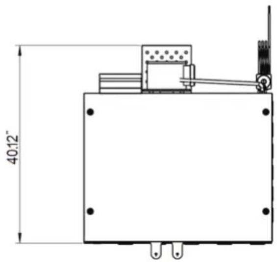
SPECIFICATIONS
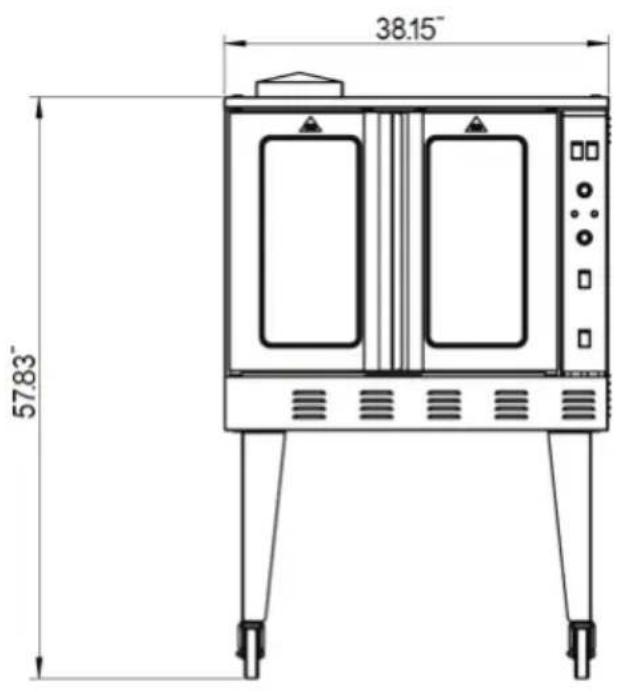
Figure 1
natural_image
Technical line drawing of a mechanical or electrical component with dimension标注 (no text or symbols present)| Model | Dimensions(W x H x D) | Net Weight | Gas Type | |||
| NG LP | ||||||
| Pressure(PSI/W.C.) | BTU | Pressure(PSI/W.C.) | BTU | |||
| M38COD | 38.2” x 57.8” x 40.1”970 x 1468 x 1019 (mm) | 408 lbs.(185 kg) | 0.144 PSI4” W.C. | 54,000 | 0.36 PSI 10”W.C. | 54,000 |
INSTALLATION INSTRUCTIONS
CAUTION: Read all instructions before installing
BEFORE INSTALLING
- Remove all packing material and tape, as well as any protective plastic from the equipment.
- Place the equipment in the desired position and height.
- Install the four (4) legs onto the equipment.
- Clean and dry the equipment thoroughly before using.
INSTALLATION
The installation of this equipment must conform with local codes, or with the National Gas Code, ANSIZ223.1/NF-PA 54, or the Natural Gas and Propane Installation Code, CSA B149.1, as applicable.
• Installation of this device should be performed by a professional technician.
- The equipment and its individual shutoff valve must be disconnected from the gas supply piping system during any pressure testing of that system at test pressures in excess of 12 psi (3.5 kPa).
- The equipment must be isolated from the gas supply piping system by closing its individual manual shutoff valve during any pressure testing of the gas supply piping system at test pressures equal to or less than 12 psi (3.5 kPa).
CLEARANCE AND POSITIONING AROUND THE EQUIPMENT
- This equipment must be installed adjacent to non-combustible surfaces only with a minimum spacing of 6" from all sides.
- This equipment must be a distance of 6" from other equipment. The equipment must have the 4" legs installed and be placed on a noncombustible surface.
- For an oven equipped with casters, the installation shall be made with a connector that complies with the Standard for Connectors for Movable Gas Appliances, ANSI Z21.69/CSA 6.16 and a quick-disconnect device that complies with the Standard for Quick-Disconnect Devices for Use with Gas Fuel, ANSI Z21.4/CSA 6.9. When installing the oven with casters and quick-disconnect hose, adequate means must be provided to limit the movement of the oven without depending on the connector and the quick disconnect device or its associated piping to limit the oven movement. Restraining means may be attached to the vertical portion of the base frame in the rear of the oven.
AIR SUPPLY AND VENTILATION
- The area in front of and around the equipment must be kept clear to avoid any obstruction of the flow of combustion and ventilation air.
- Adequate clearance must be maintained at all times in front of and at the sides of the equipment for servicing and proper ventilation.
GAS CONNECTION
Prior to connecting gas supply, check the incoming line pressure. The oven can only withstand a maximum pressure of 12 PSI (14" WC). If the line pressure is beyond this limit, a step down regulator before this machine will be required.
ELECTRICAL CONNECTION
Your oven is supplied for connection to a 115V, single phase grounded circuit. The electric motor, oven lights, indicator lights and control circuits are connected through an electric supply cord found at the rear of the oven. Warning: This appliance is equipped with a three-prong (grounding) plug for your protection against shock hazard and should be plugged directly into a properly grounded three-prong receptacle. DO NOT cut or otherwise remove the grounding prong from this plug.
Before making any connections to these units, check the rating plate to assure that the voltage and phase of the oven is compatible with the electrical supply. When installing, all ovens must be electrically grounded in accordance with local codes, or in the absence of local codes, with the National Electrical Code, ANSI/NFPA 70 (in Canada - CSA Std. C22.2). Wiring diagrams are located in the control compartment area of the oven. Standard wiring schematics are also provided with this manual.
GAS CONVERSION
Please check the rating plate for the gas type to be connected for operation. If the available gas is different from the gas type specified on the rating plate. A gas conversion procedure should be performed by a qualified technician. It is recommended that a trained gas service technician with the necessary tools, instruments and skills perform the conversion.
To convert the gas, following steps must be completed:
-
Remove all gas burner orifices and install the provided conversion kits
-
Change the Honeywell control valve. VR8205m2831 is for propane gas. VR8205A2800 is for natural gas use.
CASTER INSTALLATION
- The casters are connected by a threaded bolt. Be sure to fasten the bolt to the leg hole tightly.
NOTE: The casters with locking brakes are best mounted on the front side of the oven for easier access. - Align the leg plate holes in each leg with those in the corners of the oven bottom and secure using the provided bolts. Tighten all bolts firmly. Repeat this procedure for all legs.
NOTE: If you plan to use casters and flexible fuel gas connectors, a fixed restraint of the proper length must be incorporated to secure the oven to a non-movable surface to eliminate strain on the connector. If the oven is removed from its normal position, the restraint must then be reattached when returned.
For stacking units, please use a stacking bracket and connect two pieces with screw and install the stacking chimney assembly.
EXHAUST SYSTEM
The appliance must be positioned in a suitable area for the discharge of the combustion products. These appliances are not designed to be connected to an evacuation duct for the discharge of combustible products.
These appliances must discharge the combustible products into appropriate hoods or similar devices connected to a flue of proven efficiency, or they may be connected directly to an outdoor vent.
If it cannot be directly connected to an outside vent, the unit may be connected to an air exhaust system that leads directly outdoors, providing it has the capacity required plus the air exchange necessary in order to make operators comfortable.
NOTE: During the initial uses of the appliance, an acrid or burning smell may be detected. This will disappear after two or three uses.
INSTRUCTIONS FOR FIELD CONVERSION TO LPG GAS
⚠ WARNING: Improper installation, adjustment, alteration, service or maintenance can cause property damage, injury or death. Read the installation, operating and maintenance instructions thoroughly before installing or servicing equipment.
⚠ WARNING: This conversion kit shall be installed by a qualified service agency in accordance with the manufacturer's instructions and all applicable codes and requirements of the authority having jurisdiction. If the information in these instructions is not followed exactly, a fire, an explosion, or production of carbon monoxide may result causing property damage, personal injury or loss of life. The conversion kit should be installed by qualified service personnel. The installation is not complete until the operation of the converted appliance is checked and meets the manufacturers specifications per the instructions included with this kit.
CAUTION: Ensure the gas supply is shut off at the manual shut off valve before proceeding with the conversion.
- Shut off the gas supply and electric power to the unit and remove the side panel, exposing gas valve and control compartment.
- Disconnect gas line from gas valve so manifold assembly can be removed.
- Disconnect wiring at gas valve. Be sure to note the proper location of any and all electrical wiring disconnected.
- Remove the screws holding the manifold and gas valve to the manifold supports. DO NOT discard any screws.
- Carefully remove the manifold assembly
CHANGING THE ORIFICES
- Remove the Natural gas (brass) burner orifices from the manifold assembly and replace them with the conversion orifices furnished in the conversion kit (#55 for the pilot and #47 (2.0mm) for the burners. (Figure 1).
- Apply some thread sealant on the nozzle thread. Tighten the orifices. Make sure orifice is installed straight so that it forms a right angle (90°) to the manifold.
| Figure 1 | Changing Orifices |
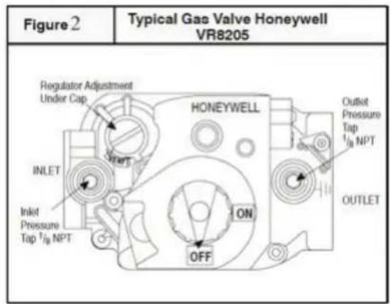
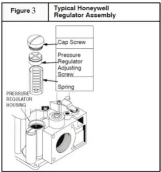
GAS VALVE CONVERSION
- Remove the regulator cap screw and pressure regulator adjusting screw. (See Figure 3)
- Remove the existing regulator spring from the regulator housing.
- Insert the replacement spring into regulator housing
- Install the pressure regulator adjusting screw and give it eight (8) full turns. This would set the manifold pressure close to required setting for normal operation.
- Replace the regulator cap screw.
- Attach gas valve conversion kit (found in Honeywell conversion kit) to gas valve.
REASSEMBLY
Reassemble all parts in reverse order as removed. Attach gas conversion label next to the unit rating plate. Fill out and attach the Field conversion label to the side panel next the other stickers.
MANIFOLD ASSEMBLY
Be sure to attach the manifold correctly. The orifice should be pointing in the center of the burner to avoid producing a lot of soot. Plug back the electrical supply and test for leaks.
Check the main burner for a stable, blue flame extending directly from the burner into the heating cavity. The flames should not have solid, yellow tips.
MANDANTORY MARKINGS
The following rating plate examples must be affixed to the rear of the unit upon conversion completion by the installer.
• Example A Rating Plate

Magic Chef®
COMMERCIAL
COMMERCIAL GAS COOKER
Model: Model Number
Orifice Size: **#
Serial: ********
Gas Type: LP (Propane)
Input: ***** BTU
Manifold Pressure: 10" WC
Max. Pressure: 13" WC
Intended for other than household use
Conforms to ANSI STD Z83.11-2016
Certified to CSA STD 1.8-2016

Intertek
Conforms to NSF/ANSI STD 4
• Example B Installation Plate
CONVERSION BY QUALIFIED SERVICE AGENCY
THIS APPLIANCE WAS CONVERTED ON:
Day ____ Month ____ Year ____
To LPG gas with KIT #: ____
By: Company Name ____
Address ____ ____ ____
Which accepts the responsibility that this conversion has been properly made.
• Example C Warning Label fixed to side of the unit
LPG
GPL
CLEARANCES
ESPACES LIBRES
FOR LP GAS WHEN EQUIPPED WITH NO. ** DRILL SIZE ORIFICE
POUR LP GAZ LORSQU'ÉQUIPÉ AVEC UNE OUVERTURE DE TAILLE DE MECHE NO. **
MAN.PRESS. PRESS.MAN.
BTU CONSOMMATION
10.0
INCH W.C.
*****
BTU INPUT/HR
| BACK ARRIERE | 6" |
| RT SIDE COTE DROIT | 6" |
| LT SIDE COTE GAUCHE | 6" |
COMPLIES WITH ANSI STD Z83.11-2016, CSA STD 1.8-2016, FOOD SERVICE EQUIPMENT
FOR YOUR SAFETY REFER TO INSTALLATION INSTRUCTIONS FOR CONVERSION PROCEDURE
OPERATION
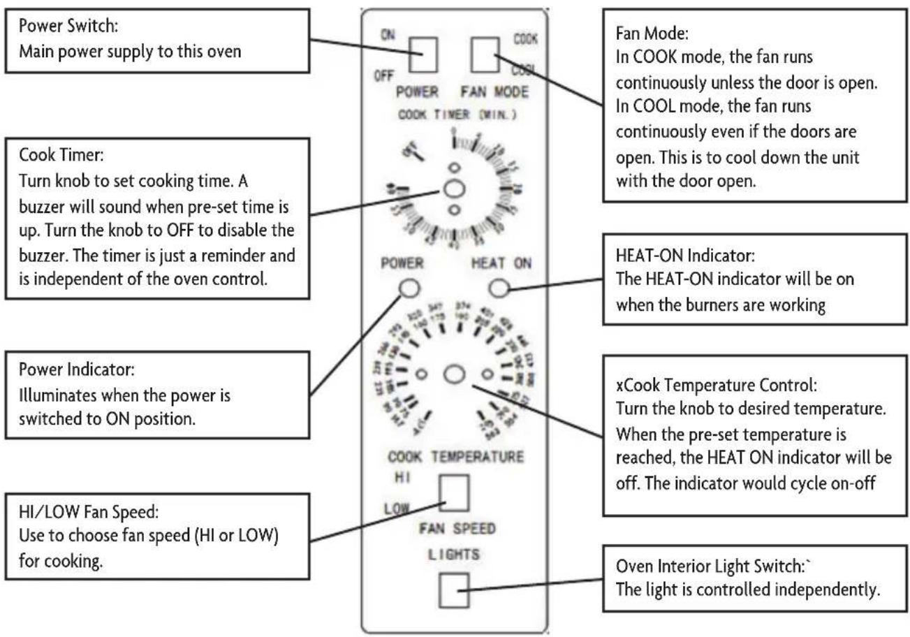
CONTROL PANEL
LIGHTING, RELIGHTING, AND SHUTDOWN INSTRUCTIONS
To light the oven, just switch the power switch at the top left corner of the control panel to the "ON" position. (The oven is equipped with a direct hot surface ignition system. There is no pilot to light.)
If the burners fail to ignite within four seconds, the oven will automatically shut off the gas. Wait five minutes to allow the gas that was released to dissipate and try to light the burners again. If the burners still fail to ignite after three such attempts, the oven will stop trying, even though the power switch is in the "ON" position. To continue to attempt to light the burners, turn the power switch "OFF" and then "ON" again.
To shut down the oven, switch the power switch to the "OFF" position. For a complete shutdown, also open the control panel and turn the manual shut-off valve to the "OFF" position.
OPERATING
Turn the power switch to the “ON” position and set the cooking temperature. Choose the desired fan speed (HI or LOW) using the Fan Speed switch. Switch the Fan Mode switch to COOK. The fan will run continuously when the oven doors are closed (the fan works independently of the gas system). If this switch is turned to COOL, the only difference is that the fan will continue to rotate when the oven doors are open. Set the cooking temperature by turning the Cook Temperature Control until the indicator mark on the knob is pointed to desired cooking temperature. The HEAT ON indicator will be on when the burners are on and will remain on while the oven is heated.
Wait until the HEAT ON indicator cycles on and off three times, indicating that the pre-set temperature has been reached. Open the oven doors, load the food to be cooked into the oven, and close the doors.
Set the cook timer as desired (up to 55 minutes). Be aware that the timer does not control the temperature of the oven. The timer knob will rotate counterclockwise as the timer runs down, indicating how much time remains. You can turn the knob while cooking to increase or decrease the remaining time. When the timer runs out, a buzzer will sound for a short time then turn itself off. (To immediately silence the buzzer, turn the Cook Timer knob to the OFF position.) If you open the oven doors during cooking, the burners and fan will shut off until the doors are closed, however the timer will continue running. For ovens that are equipped with an oven interior light, to turn on the light, press and hold the switch located at the bottom of the control panel.
After cooking, you can rapidly cool the oven by opening the oven doors (which will shut off the burners) and switching the Fan Mode to COOL (which will cause the fan to run even though the doors are open). To speed the process, switch the Fan Speed switch to HI. After cooking is done, turn the Cook Temperature Control to the lowest setting and switch the Power Switch to OFF.
CARE AND MAINTENANCE
NOTE: To maintain cleanliness and increase service life, this item should be cleaned daily. Do not spray water directly on or into the unit, as this may cause a short circuit or electrical shock.
Before cleaning or attempting to move this item always turn off and unplug the unit, and allow it to cool down completely.
Wipe the entire unit with a clean soft cloth until it is completely dry.
To avoid damage to the finish, do not use abrasive cleaners or scouring pads.
If soap or chemical cleaners are used, be sure they are completely rinsed away with clean water immediately after cleaning. Chemical residue could damage or corrode the surfaces of the unit.
To avoid serious injury or damage, never attempt to repair or replace a damaged power cord yourself. Contact a professional technician for repair service.
MAINTENANCE:
• A qualified service company should check the unit for safe and efficient operation on an annual basis.
- Gas piping shall be a certain size and installed to provide a supply of gas sufficient to meet the full gas input of the equipment.
- A manual shut off valve should be installed upstream from the manifold within 4 ft. (1.2m) of the equipment and in a position where it can be reached in the event of an emergency.
- Check entire gas piping system for leaks regularly. Using a gas leak detector or soapy water solution is recommended.
- Install equipment under efficient exhaust hood with flameproof filters with a distance of no less than 4 feet between the top of the equipment and the filters or any other combustible materials.
TROUBLESHOOTING
Before requesting any service on your unit, please check the following points:
| SolutionPossible CauseProblem | ||
| No Heat | Defective Ignitor | Call Customer Service |
| Power switch on control panel is off | Turn Power Switch to ON | |
| Doors are open | Close Doors | |
| Defective door switch | Call Customer Service | |
| Gas valve set to the closed position | Turn gas valve to the open position | |
| Oven has not reached proper temperature | Pre-set temperature is not reached | Allow oven to reach pre-set temperature |
| Problem with main temperature control | Call Customer Service | |
| Convection fan does not run | Oven has no electrical power | Check electrical supply |
| Circuit breaker tripped | Reset the breaker | |
| Doors are open | Closed doors | |
| Defective door switch | Call Customer Service | |
| Food cooks unevenly | Incorrect oven temperature | Set correct temperature or allow oven to pre-heat to correct temperature |
| Using a dark or glass baking pan | Lower oven temperature by 25°F | |
| Food is dry | Oven temperature too high | Lower temperature |
| Door opened too often | Keep oven door closed while cooking | |
| Oven cycles 3 times and locks itself out | Defective flame sensor | Call Customer Service |
Please note that this guide serves only as a reference for solutions to common problems.
WIRING DIAGRAM
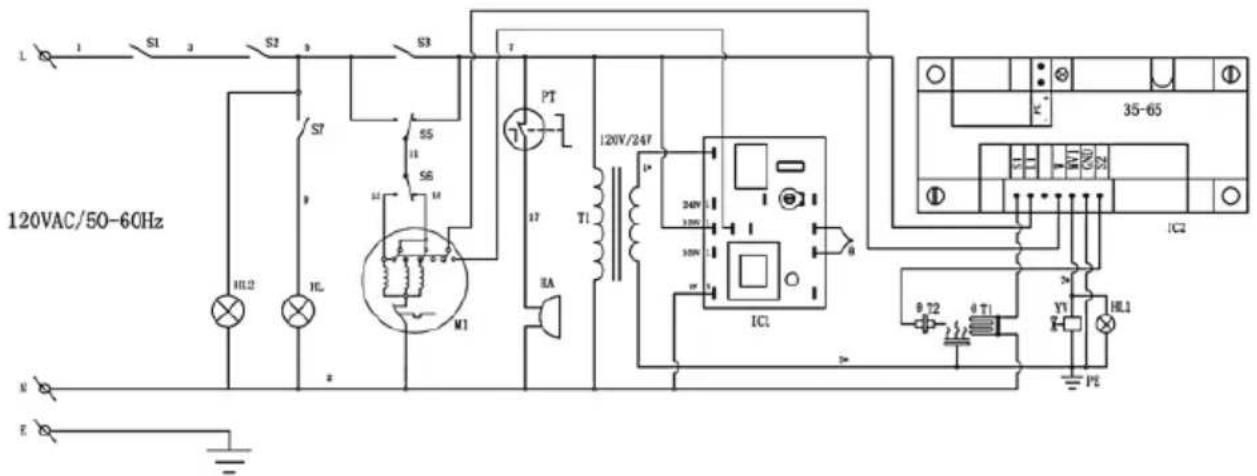
T --Gas igniter
θT2--Flame sensor
IC2--Gas controller
YV--Combination valve

LIMITED WARRANTY
MC Appliance Corporation warrants each new Commercial Stockpot Range to be free from defects in material and workmanship, and agrees to remedy any such defect or to furnish a new part(s), at the company's option, for any part(s) of the unit that has failed during the warranty period. Parts and labor expenses are covered on this unit for a period of one year from the date of purchase. A copy of the dated sales receipt or invoice is required to receive warranty service, replacement or refund.
In addition, MC Appliance Corporation warrants the magnetron (parts only) to be free from defects in material and workmanship for a period of eight years. The consumer is responsible for all labor and transportation expenses related to the diagnosis and replacement of the magnetron after the initial one-year warranty expires. In the event the unit requires replacement or refund under the terms of this warranty, the consumer is responsible for all transportation expenses to return the unit to our factory prior to receiving a replacement unit or refund. A copy of the dated sales receipt/invoice is required to receive warranty service, replacement or refund. A refund or replacement will be issued at the discretion of MC Appliance Corporation.
This warranty covers appliances in use within the contiguous United States, Alaska, Hawaii and Puerto Rico. This warranty does not cover the following:
• Damages due to shipping damage or improper installation.
• Damages due to misuse or abuse.
• Content losses due to failure of the unit.
• Inside components such as turntable, roller guide, light bulbs, etc.
• Repairs performed by unauthorized service agents.
• Service calls that do not involve defects in material and workmanship such as instructions on proper use of the product or improper installation.
• Replacement or resetting of house fuses or circuit breakers.
• Failure of this product if used for other purposes than its intended purpose.
• Disposal costs for any failed unit not returned to our factory.
• Any delivery/installation costs incurred as the result of a unit that fails to perform as specified.
• Expenses for travel and transportation for product service if your appliance is located in a remote area where service by an authorized service technician is not available.
• The removal and reinstallation of your appliance if it is installed in an inaccessible location or is not installed in accordance with published installation instructions.
• Refunds for non repairable products are limited to the price paid for the unit per the sales receipt.
- This warranty is non transferable. This warranty applies only to the original purchaser and does not extend to any subsequent owner(s).
LIMITATIONS OF REMEDIES AND EXCLUSIONS:
Product repair in accordance with the terms herein, is your sole and exclusive remedy under this limited warranty. Any and all implied warranties including merchantability and fitness for a particular purpose are hereby limited to one year or the shortest period allowed by law. MC Appliance Corporation is not liable for incidental or consequential damages and no representative or person is authorized to assume for us any other liability in connection with the sale of this product. Under no circumstances is the consumer permitted to return this unit to the factory without the prior written consent of MC Appliance Corporation.
Some states prohibit the exclusion or limitation of incidental or consequential damages, or limitations on implied warranties. This warranty gives you specific legal rights, and you may also have other rights which vary from state to state.
Model Parts & Labor Type of Service
M38COD One Year In Field Service One Year In Field Service
For Service or Assistance please call 888-775-0202 or visit us on the web at www.mcappliance.com to request warranty service or order parts.

CNA International, Inc. d/b /a MC Appliance Corporation. All rights reserved. Magic Chef® logo is a registered trademark of CNA International, Inc.
www.mcappliance.com Printed in China
- Commercial Gas Convection Oven
- Magic Chef®
- COMMERCIAL
- PRODUCT REGISTRATION
- CONTENTS
- PRECAUTIONS
- EXPLANATION OF SYMBOLS
- WARNING
- CAUTION
- IMPORTANT SAFETY INSTRUCTIONS
- FOR YOUR SAFETY
- READ AND FOLLOW THIS SAFETY INFORMATION CAREFULLY SAVE THESE INSTRUCTIONS
- SPECIFICATIONS
- INSTALLATION INSTRUCTIONS
- BEFORE INSTALLING
- INSTALLATION
- CLEARANCE AND POSITIONING AROUND THE EQUIPMENT
- AIR SUPPLY AND VENTILATION
- GAS CONNECTION
- ELECTRICAL CONNECTION
- GAS CONVERSION
- CASTER INSTALLATION
- EXHAUST SYSTEM
- INSTRUCTIONS FOR FIELD CONVERSION TO LPG GAS
- CHANGING THE ORIFICES
- GAS VALVE CONVERSION
- REASSEMBLY
- MANIFOLD ASSEMBLY
- COMMERCIAL GAS COOKER
- CONVERSION BY QUALIFIED SERVICE AGENCY
- OPERATION
- CONTROL PANEL
- LIGHTING, RELIGHTING, AND SHUTDOWN INSTRUCTIONS
- OPERATING
- CARE AND MAINTENANCE
- MAINTENANCE:
- TROUBLESHOOTING
- LIMITED WARRANTY
- LIMITATIONS OF REMEDIES AND EXCLUSIONS:
- Model Parts & Labor Type of Service
Brand : Magic Chef
Model : M38COD
Category : Oven