INV239A - Receiver Pyle - Free user manual and instructions
Find the device manual for free INV239A Pyle in PDF.

| Product Type | Home Audio Receiver |
| Model | INV239A |
| Brand | Pyle |
| Dimensions (W x H x D) | 17 x 5.5 x 12 inches |
| Weight | 12.5 lbs |
| Power Supply | 120V / 60Hz |
| Amplifier Output Power | 200W per channel (4 ohms) |
| Total Harmonic Distortion | < 0.05% |
| Frequency Response | 20Hz - 20kHz |
| Inputs | 3x RCA, 2x Optical, 1x Coaxial, 1x USB, 1x FM Antenna |
| Outputs | Speaker terminals (2 channels), Subwoofer pre-out, Headphone jack |
| Radio Tuner | FM with 30 presets |
| Remote Control | Included (IR) |
| Bluetooth | Yes, version 4.0 |
| USB Playback | MP3, WMA, WAV |
| Front Panel Display | LED with volume level and source indicator |
| Cabinet Finish | Black brushed aluminum |
| Cooling System | Internal fan, thermostatically controlled |
| Protection Circuitry | Short circuit, overheat, and overload protection |
| Included Accessories | Remote control, FM antenna, power cord, user manual |
Frequently Asked Questions - INV239A Pyle
User questions about INV239A Pyle
0 question about this device. Answer the ones you know or ask your own.
Ask a new question about this device
Download the instructions for your Receiver in PDF format for free! Find your manual INV239A - Pyle and take your electronic device back in hand. On this page are published all the documents necessary for the use of your device. INV239A by Pyle.
USER MANUAL INV239A Pyle
PYLE amplifiers provides high-performance sound reinforcement for your mobile audio equipment. Its versatility enables compatibility with optional Equalizers, Frequency Dividing Crossover Networks, and other audio processors in customized system. The Multi-Mode bridging capabilities allow flexibility in hosting several different speaker configurations.
To achieve optimum performance, it is highly recommended that you read this Owners Manual before beginning installation.
WARNING!
High powered audio systems in a vehicle are capable of generating "Live Concert" high levels of sound pressure. Continued exposure to excessively high volume sound levels may cause hearing loss or damage.
Also, operation of a motor vehicle while listening to audio equipment at high volume levels may impair your ability to hear external sounds such as; horns, warning signals, or emergency vehicles, thus contributing to a potential traffic hazard. In the interest of safety, PYLE recommends listening at lower volume levels while driving.
TABLE OF CONTENTS
TROUBLESHOOTING GUIDE 16
SPECIFICATION 17
Before beginning the installation, consider the following
- Do you plan to add additional mobile electronics equipment in the future?
If you plan to expand your system by adding other components sometime in the future, ensure adequate space is left, and cooling requirements are met.
- Should you use high or low level inputs?
Your Amplifier has been designed to accept Low-Level (Pre-Amp outputs from your radio) signal source. If your radio/source is equipped with Pre-Amp outputs, it is possible to utilize them to drive the Amplifier and connecting (Amplifier) to the 2 rear speakers. Then, use the built-in power of your radio to drive the 2 front speakers.
- Are your components matched?
The RMS power rating of your speaker's must be equal or greater than the RMS power rating of your amplifier. You speaker(s) also must be 2-8 Ohms impedance for stable amplifier operation. Impedance information is normally printed on the speaker basket or magnet.
- Where will the amplifier be installed?
Consider both the length of your leads and routing when determining the mounting location. It is best to run power and RCA wiring on opposite sides of the vehicle to prevent induced noise. Pre-Amp input Jacks require a length (depending on location) of high qualityshielded male to male RCA patch cord.
WIRING CONNECTION
CAUTION:
AS A PRECAUTION, DISCONNECT THE POWER WIRE FROM THE BATTERY WHILE MAKING THE POWER AND GROUND CONNECTIONS TO THE AMPLIFIER.
4/8 GAUGE (Thicker if planning for additional Amplifiers) wire is recommended for both the power and ground wires. 12 Gauge, For the remote turn-on wire, 16 Gauge. Both types are available at most Mobile Audio Dealers or Installation Shop.
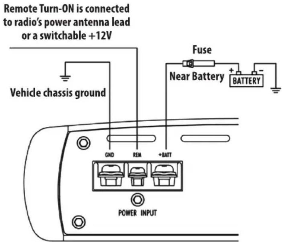
1. Ground: To Vehicle Chassis
To avoid unwanted ignition noise caused by ground loop, it is essential that the Amplifier be grounded to a clean, bare, metal surface of the vehicle's Chassis.
NOTE:
GROUND WIRE SHOULD NOT BE EXTENDED MORE THAN 3 FT, (1 METER).
2. +12 Volt (Fused) Constant Power: To Battery (+)
Due to the power requirements of the Amplifier, this connection should be made directly to the positive (+) terminal of battery. For safety measures, install an in-line Fuse Holder (not included) as close to the battery positive (+) terminal as possible. With an ampere rating not to exceed total value of fuses in Amp.
3. Remote Turn-On Input: To Power Antenna output of Car Stereo
This Amplifier is turned "ON" remotely when the vehicle's stereo is turned "ON". NOTE: IF YOUR RADIO DOES NOT HAVE A+12 VOLT OUTPUT LEAD WHEN THE RADIO IS TURNED ON, REMOTE TERMINAL ONTHE AMPLIFIER CAN BE CONNECTED TO VEHICLE'S ACCESSORY CIRCUIT THAT IS LIVE WHEN THE KEY IS "ON".
text_image
Remote Turn-ON is connected to radio's power antenna lead or a switchable +12V Vehicle chassis ground Fuse Near Battery + - BATTERY GND REM +BATT POWER INPUTPANEL LAYOUT
INV139A/INV159A FRONT VIEW
text_image
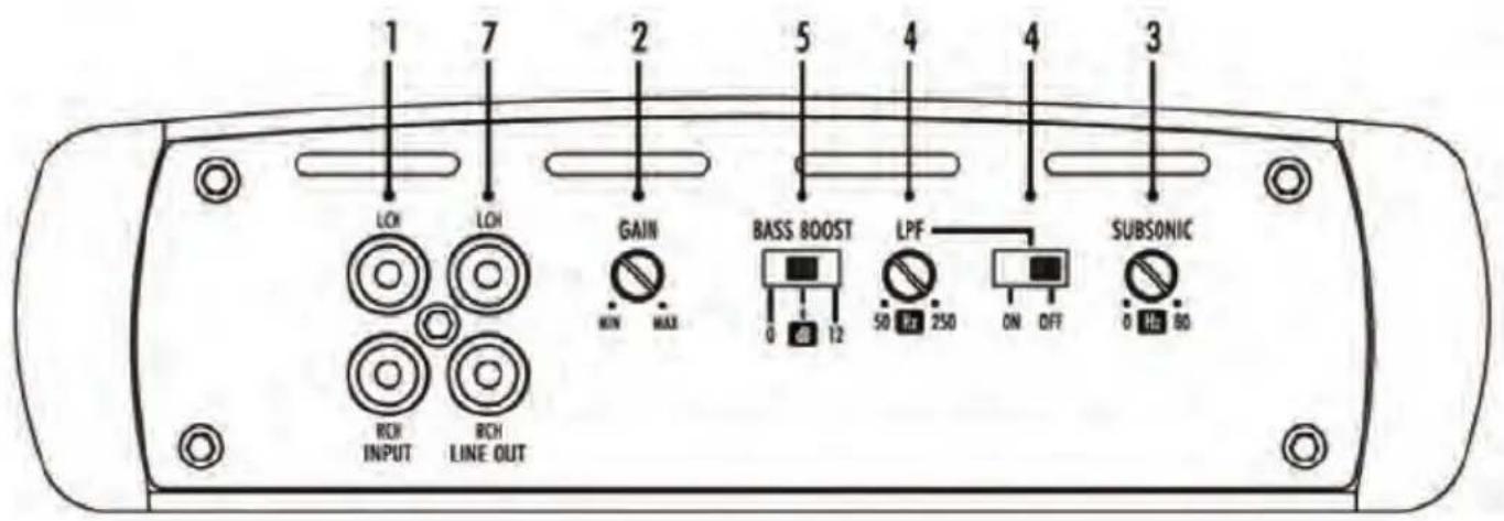
1 7 2 5 4 3 LOH LOH GAIN BASS BOOST LPF SUBSONIC 0 12 50 250 ON DFT 0 Hz 80 RCH INPUT RCH LINE OUTINV239A/INV259A FRONT VIEW
text_image
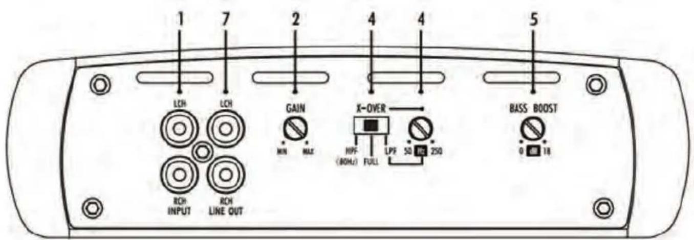
1 7 2 4 5 LDH LCH GAIN X-OVER BASS BOOST MIN MAX HPF (80Hz) FULL LPF 50 FC 250 ROH INPUT ROH LINE OUT 0 18INV449A FRONT VIEW
text_image
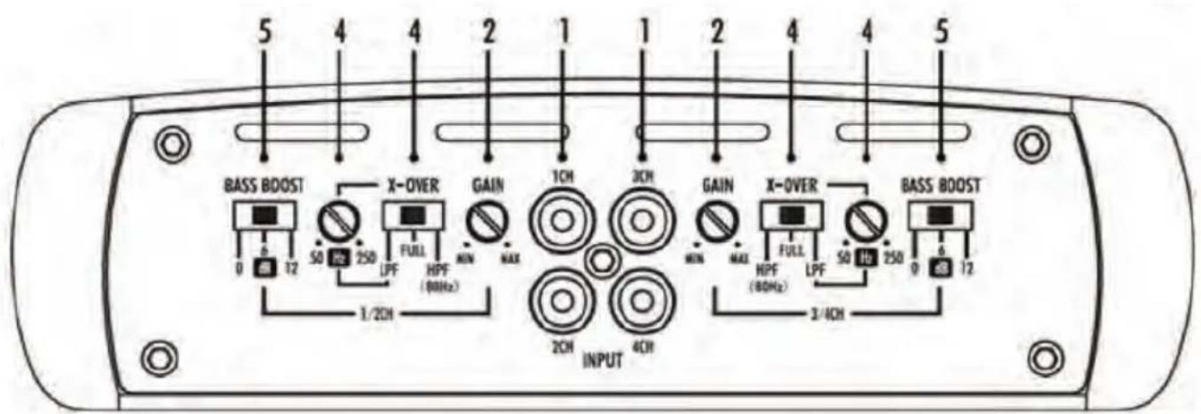
5 4 4 2 1 1 2 4 4 5 BASS BOOST X-OVER GAIN 1CH 3CH GAIN X-OVER BASS BOOST 0 12 50 250 FULL HPF (80Hz) MIN MAX MIN MAX HPF (80Hz) 50 10 250 0 6 12 1/2CH INPUT 4CH 3/4CHINV139A/INV159A REAR VIEW
text_image
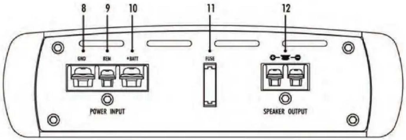
8 9 10 11 12 GND REM +BATT FUSE POWER INPUT SPEAKER OUTPUTINV239A/INV259A REAR VIEW
text_image
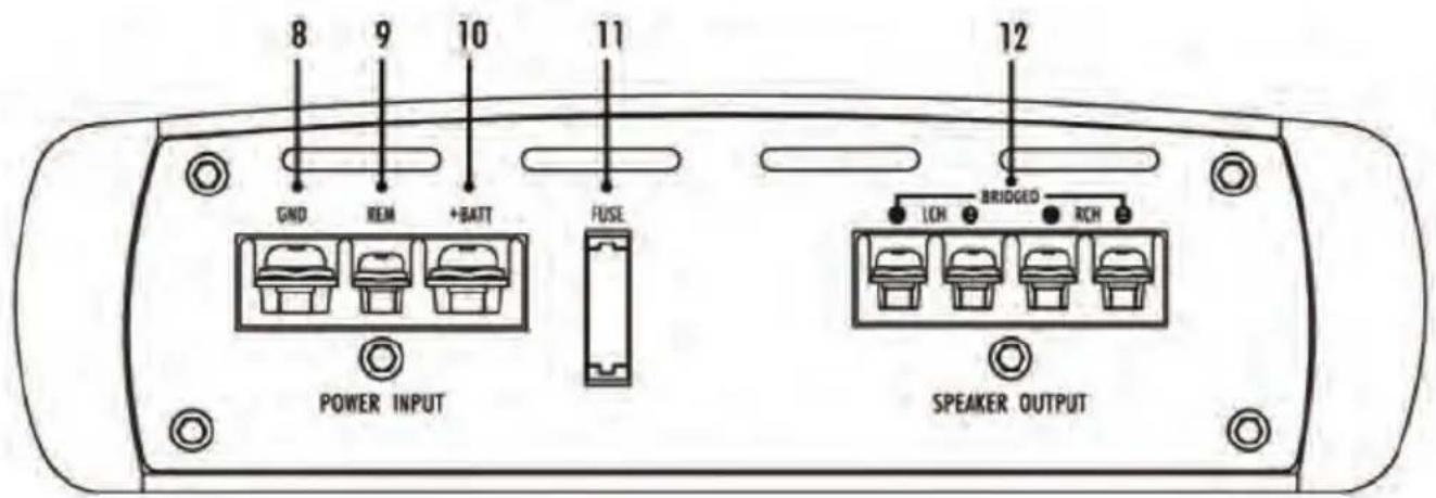
8 9 10 11 GND REM +BATT FUSE 12 POWER INPUT LED BRIDGED RCH SPEAKER OUTPUTINV449BA REAR VIEW
text_image
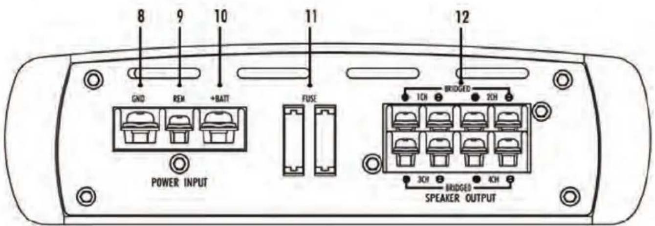
8 9 10 11 12 GND REM +BATT FUSE POWER INPUT 1CH BRIGDED 2CH 3CH BRIGDED 4CH SPEAKER OUTPUTTOP VIEW
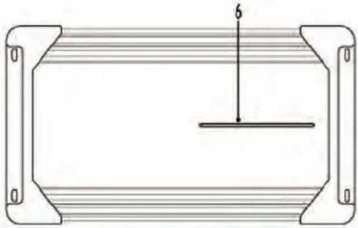
INV139A/INV239A TOP VIEW
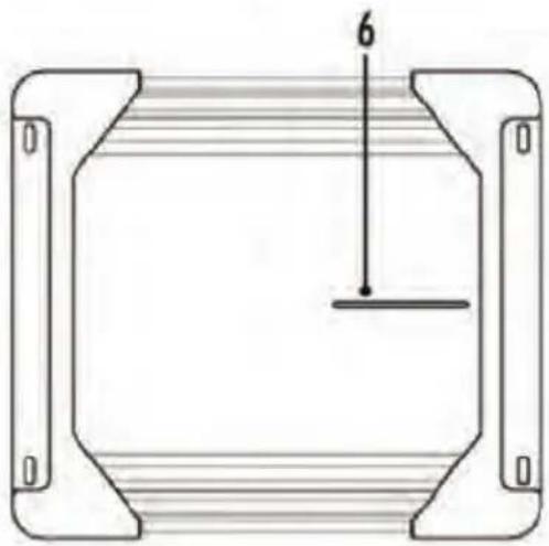
natural_image
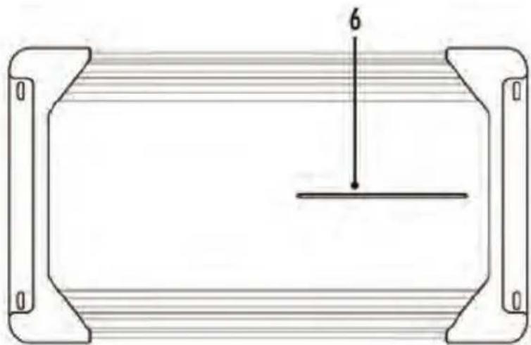
Pure technical diagram of a rectangular frame with internal horizontal lines and a vertical dimension labeled '6' (no text or symbols beyond the number)INV159A/INV259A TOP VIEW
natural_image
Pure technical diagram of a rectangular frame with internal horizontal lines and a central horizontal line, no text or symbols present.INV449A TOP VIEW
natural_image
Pure technical diagram of a rectangular frame with internal horizontal lines and a vertical dimension labeled '6' (no text or symbols beyond the number)CONTROL FUNCTIONS
1. RCA Input jacks
These RCA input jacks are for use with source units that have RCA or Line level outputs. A source unit with a minimum level of 200mV is required for proper operation. The use of high quality twisted pair cables is recommended to decrease the passivity of radiated noise entering the system.
2. GAIN Control
The level control will match the amplifiers sensitivity to the source units signal voltage. The operating range is 200mW minimum to 6W maximum.
CAUTION: Do not run the amplifier in high volume for long time. Otherwise the loudspeakers will be damaged.
3. SUBSONIC
IN139MINV159A: The frequency can be adjusted between 0Hz and 80Hz.
4. X-OVER
*Full pass x-over switch
When the switch is in Full position, the full range is bypassed.
* Low Pass x-over switch
When the switch is in "LPF" position, frequencies lower than the low pass, frequency setting are passed.
IN139A/INV159A/INV239A/INV259A/INV449A:
The frequency can be adjusted between 50Hz and 250Hz.
*High pass x-over switch
When the switch is in HPF position, frequencies higher than the high pass frequency setting are passed.
IN239/INV259A/INV449A: The frequency is 80Hz.
5. Bass BOOST
INV239A/INV259A: The boost can be adjusted between 0dB to 12dB.
IM139A/INV159A/INV449A: The boost can be selected among 0dB, 6dB and 12dB.
6. LED
Will illuminate BLUE to indicate the amplifier is on and operating normally, and will be laminated RED if the amplifier shuts down due to short circuit DC offset, or overheating detected by on board protection circuitry.
7. Auxiliary Outputs
The Auxiliary outputs offer PYLE amplifiers easy, unlimited system expansion. Route RCA, from the line out of the first amplifier to the line input of a second amplifier when using a single source output.
8. GND
Connect this terminal directly to the sheet metal chassis of the vehicle using the shortest wire necessary to make this connection. Always use wire of the same gauge or larger than the (+) 12 volt power wire.
The chassis connection point should be scraped free of paint and dirt.
Use only quality crimped and/or soldered connectors scraped free of paint and dirt. Use only quality crimped and/or soldered connectors
WARNING:
Do not connect this terminal directly to the vehicle battery ground terminal or any other factory ground points.
9. Remote Turn On
This terminal turns on the amplifier when (+) 12 volt is applied to it.
Connect it to the remote turn on lead of the head unit or signal source.
10. (+) 12 Volt Power
Connect this terminal through a FUSE or CIRCUIT BREAKER to the positive terminal of the vehicle battery or the positive terminal of an isolated audio system battery.
WARNING:
Always protect this power wire by installing a fuse or circuit breaker of the appropriate size within 12 inches of the battery terminal connection.
11. FUSE
These fuses protect the amplifier against internal electrical damage and are meant to protect the amplifier only. All other power connections should be fused at the source.
- SPEAKERS: Connect subwoofers to these terminals.
SPEAKER CONNECTION
MONO Channel System Design #1
INV139/INV159A
text_image
04 - 12dB 3685 LCH LCH GAIN BASS BOOST LPF SUBSONIC RCH INPUT RCH LINE OUT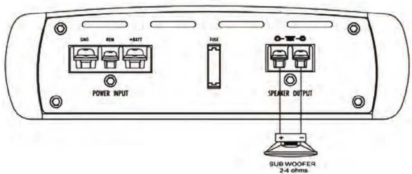
text_image
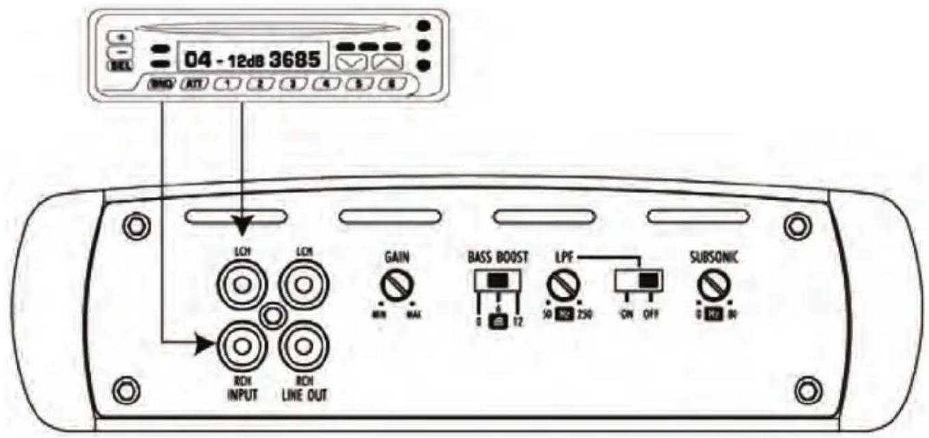
CANO REN +BEITT POWER INPUT FUSE SPEAKER OUTPUT SUB WOOFER 2-4 ohms2 Channel System Design #1 INV239A/INV259A
text_image
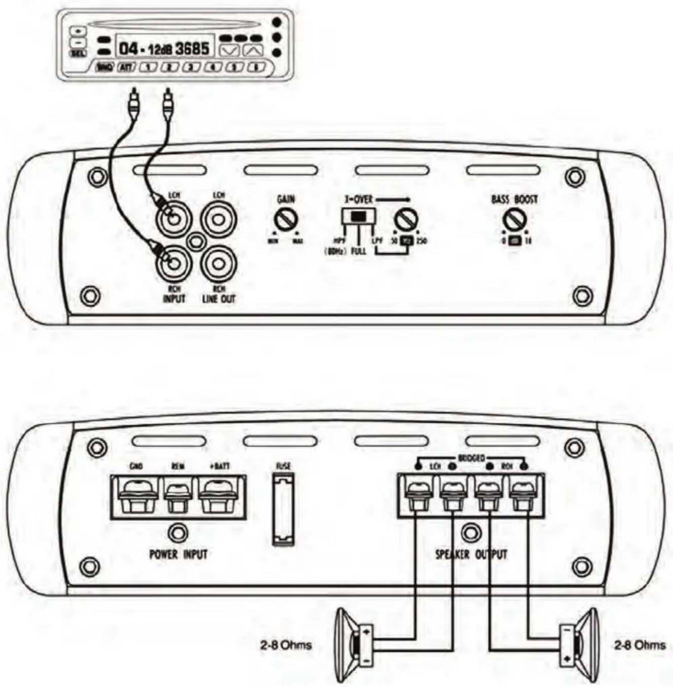
04 - 12dB 3685 REL AUTO ATT 1 2 3 4 5 6 7 8 LCH LCH GAIN MAX I-OVER HPPF (80Hz) FULL UPF 50 250 BASS BOOST 0 18 RCN RESM +BATT FUSE POWER INPUT LED BRDGED REN SPEAKER OUTPUT 2-8 Ohms 2-8 Ohms2 Channel System Design #2 INV239A/259A
text_image
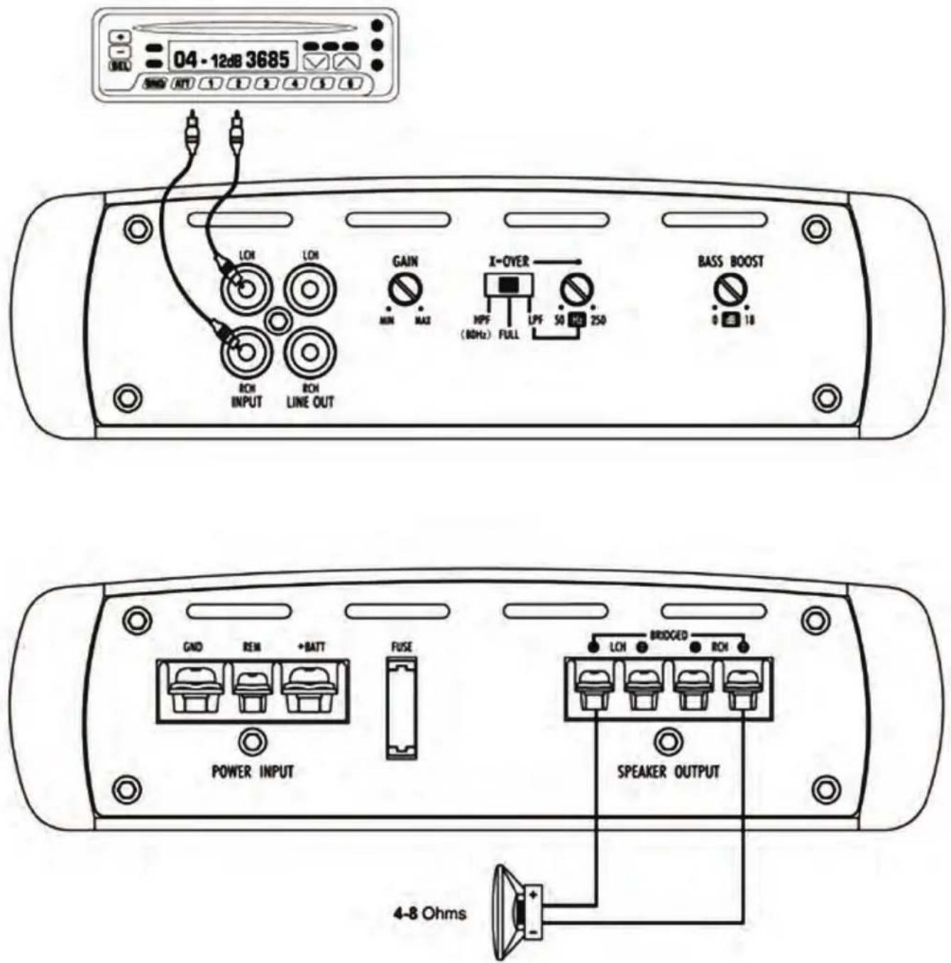
04 - 12dB 3685 SHEU SHEU AIR 1 2 3 4 5 6 7 8 LCH LCH GAIN X-OVER BASS BOOST MIN MAX HPF (80Hz) FULL LPF 50 250 0 18 RON INPUT RON LINE OUT GND REM +BATT FUSE POWER INPUT LCH BRIDGED RON SPEAKER OUTPUT 4-8 Ohms2 Channel System Design #3
INV239A/259A
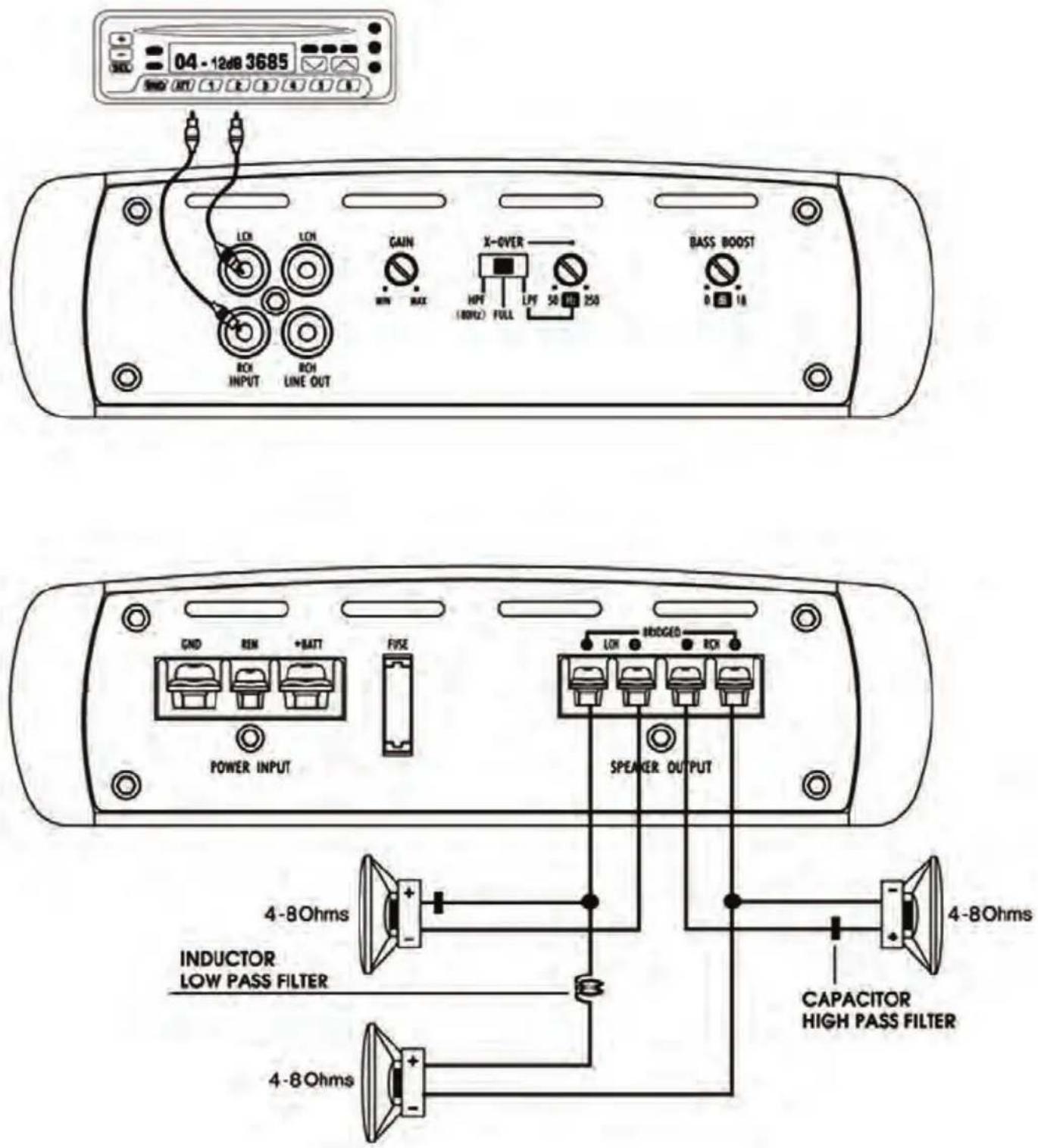
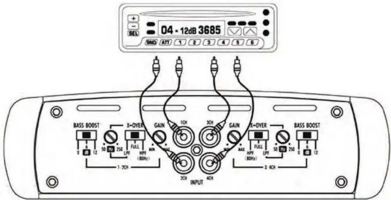
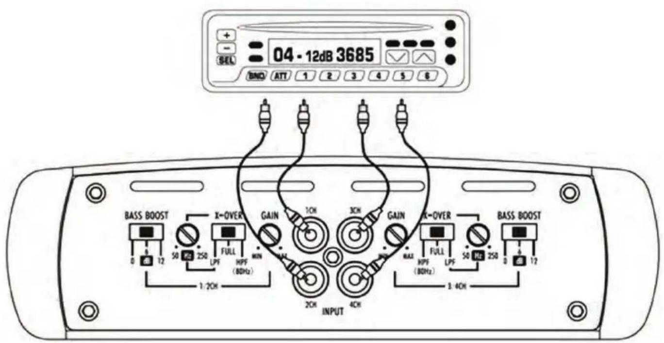
4 Channel System Design #1 INV449A
text_image
04 - 12dB 3685 BNO ATT 1 2 3 4 5 6 BASS BOOST X-OVER GAIN 1OH 3OH GAIN X-OVER BASS BOOST 1 2OH 3OH 4OH FULL HPF (80Hz) MAX MAX FULL HPF (80Hz) 50 HD 250 0 6 12 1:2CH INPUT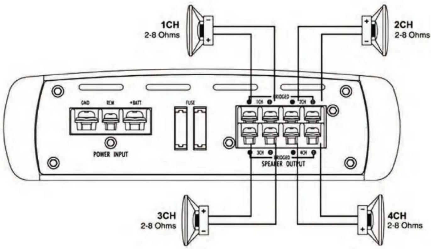
text_image
1CH 2-8 Ohms 2CH 2-8 Ohms GND REM +BATT FUSE POWER INPUT 1CH BRIDGED 2CH 3CH BRIDGED 4CH 2-8 Ohms SPEAMER OUTPUT4 Channel System Design #2
INV449A
text_image
04 - 12dB 3685 BND ATT 1 2 3 4 5 6 BASS BOOST X-OVER GAIN 1OH 3OH GAIN OK-OVER BASS BOOST 0 12 50 250 FULL MAX LPF (80Hz) 1:2OH INPUT 2OH 4OH MAX RASS 30PF (80Hz) LPF 50 Hz 250 0 12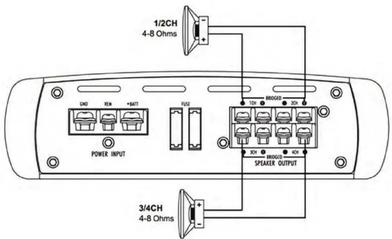
text_image
1/2CH 4-8 Ohms GND REM +BATT POWER INPUT FUSE 1OH BRIODGED 2OH 3OH BRIODGED 4OH SPEAKER OUTPUT 3/4CH 4-8 OhmsTROUBLESHOOTING GUIDE
| Issue Possible Cause Solution | ||
| NO SOUND | Is the power LED illuminated? | Check all fuses, replace if necessary.Make sure the power is securely fastened. |
| UNIT WILL NOT TURN ON | No power to power wire | Repair power wire or connections |
| No power to remote wire with receiver on | Check connections to radio | |
| Fuse broken Check | all fuses, replace if necessary | |
| NO SOUND IN ONE CHANNEL | Check speaker leads | Inspect for short circuit or an open connection |
| Check audio input leads | Reverse Left and Right RCA inputs to determine if it is occurring before the amp.Check Tune/Deck volume level.Clean the contacts on fuse holders. | |
| AMP TURNING OFF MEDIUM HIGH VOLUME | Check speaker load impedance | Be sure proper speakers are used to ensure impedance recommendations are observed.(If you use an Ohm meter to check speaker resistance, please remember that DC resistance and AC impedance may not be the same.) |
WARNINGS
Investigate the layout of your automobile thoroughly before you drill or cut any holes. Take extra care when working near gas tanks, fuel lines, brake or hydraulic lines and electrical wiring. Never operate the amplifier when it is unmounted. Attach all audio system components securely to prevent damage, especially in an accident. Don't mount this system so that the wire connections are unprotected or are subject to pinching or damage from nearby objects. The +12V DC power wire must be fused at the battery positive terminal connection. Before making or breaking power connections in your system, disconnect the vehicle battery. Confirm that your head unit or other equipment is turned off while connecting the input jacks and speaker terminals. If you need to replace the power fuse, replace it only with a fuse identical to that supplied with the amplifier. Using a fuse of a different type or rating may result in damage to your audio system or your amplifier which is not covered by the manufacturer's warranty.
SPECIFICATIONS
| INV139A | INV159A INV239A INV259A INV449A | ||||
| MAXIMUM POWER OUTPUT | 2000W | 3000W | 1000W | 2000W | 2000W |
| POWER OUTPUT RMS @40hm | 1CHx350W | 1CHx650W | 2CHx250W | 2CHx500W | 4CHx250W |
| POWER OUTPUT RMS @20hm | 1CHx900W | 1CHx1500W | 2CHx350W | 2CHx650W | 4CHx350W |
| BRDGED POWER MAX @40hm | NONE | NONE | 1CHx1000W | 1CHx2000W | 2CHx1000W |
| THD | 0.01 | 0.01 | 0.01 | 0.01 | 0.01 |
| FREQYENCY RESPONSE -3.00B | 45KHz | 45KHz | 45KHz | 45KHz | 45KHz |
| HPF | NONE | NONE | 80Hz | 80Hz | 80Hz |
| LPF | 50-250Hz | 50-250Hz | 50-250Hz | 50-250Hz | 50-250Hz |
| SUBSONIC | 0-80Hz | 0-80Hz | 0-80Hz | 0-80Hz | NONE |
| BASS BOOST (50Hz) | 0,6,12dB (selectable) | 0,6,12dB (selectable) | 0,6,12dB (selectable) | 0,6,12dB (selectable) | 0,6,12dB (selectable) |
| ADJUSTABLE SENSITIVITY RANGE | 0.2-6V | 0.2-6V | 0.2-6V | 0.2-6V | 0.2-6V |
| INPUT IMPEDANCE (LOW LEVEL) | 20K | 20K | 20K | 20K | 20K |
| FUSE | 30Ax1 | 40Ax1 | 25Ax1 | 40Ax1 | 25Ax2 |
| PRODUCT DIMENSIONS (L x W x H) | 9.21" x 8.13" x 2.28" -in | 12.36" x 8.13" x 2.28" -in | 9.21" x 8.13" x 2.28" -in | 12.36" x 8.13" x 2.28" -in | 14.33" x 8.13" x 2.28" -in |
PYLE®
PyleUSA.com
Questions? Comments?
We are here to help!
Phone: (1) 718-535-1800
Email: support@pyleusa.com