DNS 4 - Processor CEDAR - Free user manual and instructions
Find the device manual for free DNS 4 CEDAR in PDF.


| Type | Processor |
| Brand | CEDAR |
| Model | DNS 4 |
| Socket Type | LGA 1151 |
| Core Count | 4 |
| Thread Count | 8 |
| Base Clock Speed | 3.2 GHz |
| Max Turbo Frequency | 4.0 GHz |
| Thermal Design Power (TDP) | 65 W |
| Integrated Graphics | Intel UHD Graphics 630 |
| Cache L3 | 8 MB |
| Memory Support | DDR4-2666, Dual Channel |
| Max Memory Size | 64 GB |
| Dimensions (L x W x H) | 37.5 x 37.5 x 4.4 mm |
| Weight | 48 g |
| Power Connector | 8-pin EPS 12V |
| Max Operating Temperature | 100 °C |
| Cooling Solution | Fan or liquid cooling required |
| Cleaning Method | Use compressed air to remove dust; avoid liquids. |
| Safety Precautions | Handle by edges; avoid static discharge; install in anti-static environment. |
| Spare Parts Availability | Not applicable; processor is a single integrated unit. |
| Warranty | 3 years limited |
Frequently Asked Questions - DNS 4 CEDAR
User questions about DNS 4 CEDAR
0 question about this device. Answer the ones you know or ask your own.
Ask a new question about this device
Download the instructions for your Processor in PDF format for free! Find your manual DNS 4 - CEDAR and take your electronic device back in hand. On this page are published all the documents necessary for the use of your device. DNS 4 by CEDAR.
USER MANUAL DNS 4 CEDAR
natural_image
Green circular logo with a white upward-pointing triangle and a curved base (no text or symbols)
DNS 4 dialogue noise suppressor
OWNER'S MANUAL
© 2022 CEDAR Audio Ltd
Manual version 1.00 September 2022
Intentionally left blank
Table of Contents
Introduction to the DNS 4....5
Safety instructions 6
Setting up the DNS 4 ....7
The front panel.... 12
The process page.... 14
The channel setup page.... 16
The global setup page 17
Using the DNS 4 19
Processing 20
Summary of operation.... 22
Additional information 23
Declaration of conformity 25
3rd-party Licence 26
Contact information 27
Specifications 28
Licence and limited warranty 30
Intentionally left blank
Introduction to the DNS 4
The DNS 4 is a further development of the DNS technology introduced in our Academy Award® winning DNS1000 and subsequent dialogue noise suppressors. Despite offering four channels of noise suppression, it is small, light and portable, and its slick user-interface allows users to obtain optimum results almost instantly and with the minimum of effort. It also retains the near-zero latency of its predecessors and, with its 4-pin 12VDC power socket, it's suitable for use in all live situations - not just on location and for live-to-air broadcasting, but also for live sound in venues such as theatres, concert halls, conferences venues, and places of worship.
Quality, speed and simplicity were paramount considerations when designing the DNS 4, which offers the following:
Near zero latency
Its low latency ensures that there is no loss of lip-sync.
Flexibility
It's able to handle a wide range of noise suppression requirements.
■ Speed and ease of use
Its carefully designed user-interface maximises speed and ease of use.
12VDC power
It accepts power from industry standard adapters and power packs for use anywhere in the world.
■ Powerful processors
The latest technology to ensure that it will handle the most complex processing requirements.
Safety instructions
Read these instructions, and follow them.
Water and moisture
The DNS 4 must not be exposed to rain or moisture. Furthermore, if it is brought directly from a cold environment into a warm one, moisture may condense inside it. This, in itself, will not cause damage, but may cause electrical shorting. This could damage the unit, and even cause danger to life. Always allow the unit to reach ambient temperatures naturally before connecting the mains power.
■ Mounting and ventilation
You should place the DNS 4 on a flat, stable surface or in a suitable equipment bag. Do not subject it to strong sunlight, excessive dust, mechanical vibration or periodic shocks. It is not susceptible to excessive heat build-up, but should be installed away from heat sources such as radiators and audio devices that produce large amounts of heat.
Power sources
The DNS 4 operates on nominally 12VDC power, although it will operate on voltages in the range from 8V - 17.5V. You should route power cables so that they will not be walked on or pinched. Unplug the supply cord to isolate the external PSU from the mains supply if it is not to be used for some time. Grasp the supply cord by the plug, never by the cord itself.
Connections
Turn off the power to all equipment before making any connections. In order to comply with EMC regulations, you must use metal-shelled connectors and good quality shielded cable suitable for AES3 connections.
Cleaning
Clean the DNS 4 only with a dry cloth. Never use abrasive pads, water or liquid cleaners such as alcohol or benzene.
■ Damage requiring service
The DNS 4 contains no user-serviceable parts and should on no account be opened or dismantled by unauthorised personnel. A unit should be returned to qualified service agents when it has been exposed to liquids, when it fails to function correctly, when it has been dropped, or when the case is damaged.
Setting up the DNS 4
Intentionally left blank
Unpacking
Unpack the DNS 4 carefully. Save the carton and all packing materials since you may need them to transport the unit in the future. In addition to the DNS 4 and its packaging, the box should contain the following:
• 12V DC power supply
• start-up and safety instructions sheet
- a warranty registration card
To maintain reliability and prolong operating life, observe the following environmental considerations:
- the temperature should be maintained between 5 and 30 Celsius
• relative humidity should be in the range 30% to 80% non-condensing
• strong magnetic fields should not exist nearby.
Power source
A 12V PSU is included with the DNS 4 and this will work on any mains supply in the range 85V to 250V, 50/60Hz AC. Connect its output to the DNS 4 power input and then plug it into the mains supply.
Audio setup
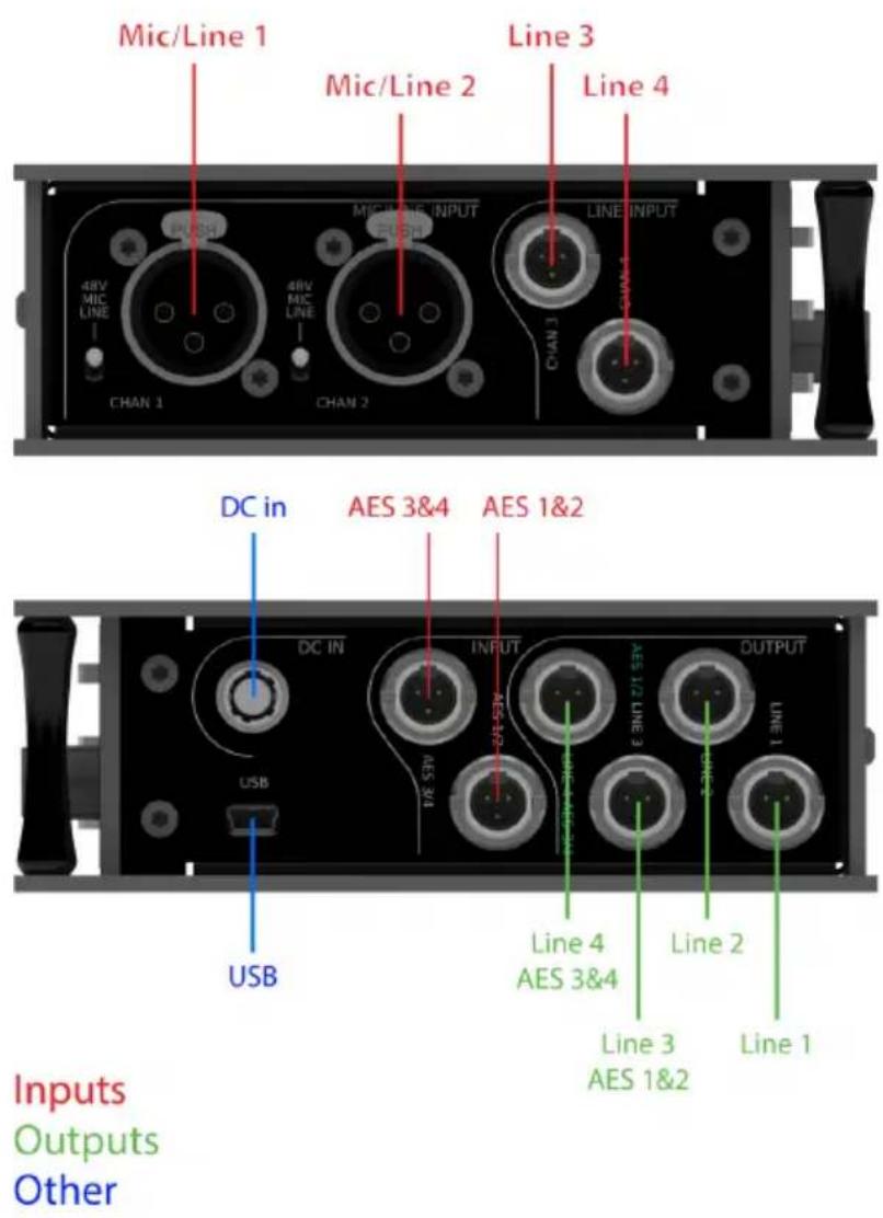
The audio connectors are on the sides of the unit; analogue inputs are on the left, while analogue outputs and all digital I/O are on the right side. Connections of a similar function are grouped together, with the low channel numbers within each group towards the rear of the unit.
Inputs
There is a single global user control to switch between analogue or digital inputs. (See Global setup.)
When analogue inputs 1&2 are in use, a pair of three-position switches select between line, microphone and microphone with +48V phantom powering for each of these channels.
■ Outputs
The first two output sockets are dedicated analogue line outputs for channels 1&2. The next two are dual-purpose and can carry either analogue or digital signals according to the user setup option. (See Global setup.)
All of the outputs are active when any analogue I/O is selected. When digital operation is selected for both the inputs and the outputs, the analogue circuitry is turned off to save power and the Line 1 and Line 2 outputs are not operational.
Audio clock
A single audio clock is used for the DSP, ADC, DAC and AES3 transmitter. When analogue I/O is used, the internal 48kHz clock is used. When AES3 input 1&2 is connected, the clock is derived from that source. Operation at 44.1kHz, 48kHz and 96kHz is supported.
USB
There is a USB socket for updating the firmware. You can also obtain this manual from the DNS 4's internal storage via USB.
The front panel
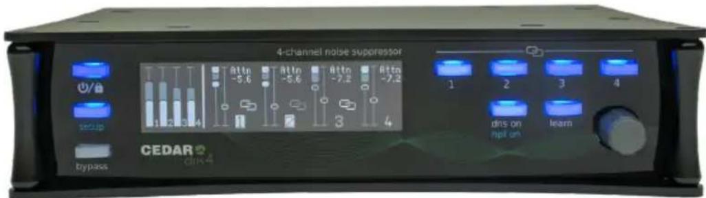
The DNS 4 front panel is divided into three sections: a set of three fixed-function buttons to the left, an OLED screen, plus six context-sensitive buttons and an encoder to the right.
The screen dims to a lower brightness after a few seconds of inactivity, and returns to full brightness when any control is operated.
Pages
There are three control pages, and the functions of the context-sensitive controls depend on which is active:
Process
The main page displays control and status information about the processing.
Channel setup
Allows access to options that are specific to a given channel.
Global setup
Allows access to unit-wide options, and also displays static information about the unit.
Fixed-function buttons
Power/lock
The DNS 4 switches on automatically when power is applied and displays the Process page. This guarantees that it reboots after a power failure. The Power/lock button is illuminated while the unit is powered on.
Once the DNS 4 is powered up, you can press the Power/lock button a second time to lock the panel. When it's locked, the Power/lock and Setup buttons continue to operate, but all the other controls are disabled. Hold down the Power/lock button for around three seconds to unlock the panel.
When the panel is unlocked, you can switch the DNS 4 off by pressing and holding the Power/lock button for around three seconds. The current settings will be stored during shutdown and will be recalled when the unit is turned on again. If the unit is not shut down correctly, the settings may not be stored.
The DNS 4's current settings are also stored a few seconds after you stop adjusting the controls.
Should something cause the unit to freeze, you can switch it off by a holding the Power/lock button for approximately six seconds.
Setup
The Setup button cycles through additional pages to access the setup parameters. It's illuminated when the unit is displaying pages other than the Process page.
Bypass
The Bypass button acts as a global process on/off control. When active, it's illuminated and the noise reduction process is disabled on all four channels. The input gain and high-pass filter (see Channel setup) are unaffected by the bypass state.
It offers two actions:
Short press
Toggles between bypass on and off
Long press
When bypass is off, pressing and holding the button acts as a preview, switching bypass on for as long as the button is held. Then, when released, bypass returns to the off state.
The process page
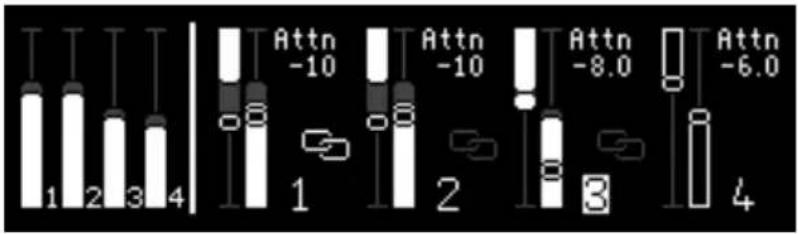
The DNS 4 boots into the Process page and returns to it from any other page after a short timeout. This displays information about all four channels simultaneously.
■ Input level meters
The left of the display shows input level meters for each of the four channels. These are for information only; the input gain controls are available in the Channel setup page.
■ Process readouts
The rest of the display shows the process settings for each of the four channels. The information shown for each channel is:
• the noise Attenuation
- the Bias
- the linking status
Channel linking
You can link certain combinations of channels into groups. Grouping channels makes them adopt identical settings, and allows you to adjust them together. The channels in a group share the same values of the following parameters:
- input gain
• high-pass filter on/off - processing on/off
- learn on/off
- Attenuation
- Bias
Nonetheless, the Learn function continues to work independently for each channel in a group and the signal processing itself is not linked. This ensures that, if the parameters are appropriate, the processing is appropriate for the signal in each channel.
The permissible combinations of groups are as follows:
| Channels: | 1 | 2 | 3 | 4 |
| Independent | - | - | - | - |
| First pair linked | 1&2 | - | - | |
| Second pair linked | - | - | 3&4 | |
| Two pairs linked | 1&2 | 3&4 | ||
| All linked | 1&2&3&4 | |||
You create a group by pressing simultaneously the channel selection buttons for the first and last channels to be included in it. Pressing the same pair of buttons again destroys the group and the channels return to being independent.
When a group is created, the process parameters from the lowest-numbered channel in the new group are copied to the other channel(s) in the group. No process parameters are changed when a group is destroyed.
Groups can be created and destroyed on both the Process page or the Channel setup page; the operation is identical in both cases. Note that the channel linking/grouping operates independently of split mode. (See Global setup.)
The channel setup page
Pressing Setup once accesses the Channel setup page.
■ Digital inputs selected (see Global setup)
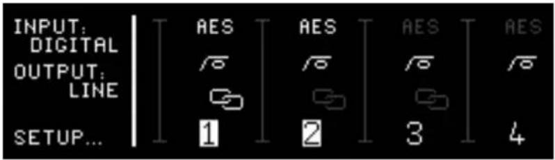
If digital inputs are selected, the page displays:
• the input source for the active channels (see Global setup)
• the high-pass filter status for each channel
- the linking status
The unit will lock to any AES3 signal with a nominal sample rate of up to 96kHz that is presented to its inputs. Operation is supported at 44.1kHz, 48kHz and 96kHz.
■ Analogue inputs selected (see Global setup)
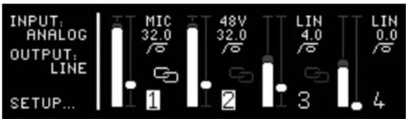
When the analogue inputs are used, a second vertical display is shown for each channel. This is the input gain, and you adjust this by selecting the appropriate channel and turning the encoder.
Note that, if channel 1 is set to MIC or 48V and channel 2 is set to LINE (or vice versa) their gain and high-pass filter settings remain independent, even if channels 1 and 2 are linked.
■ High-pass filter
An 80Hz, -18dB/oct high-pass filter is available for each input. To toggle this on and off for any channel, press any of the row of four channel access buttons at the top right of the unit to bring its associated channel (or group) into focus. When a channel is in focus, the dns on button toggles the high-pass filter.
An icon in each channel display will show whether the filter is active or not.
The global setup page
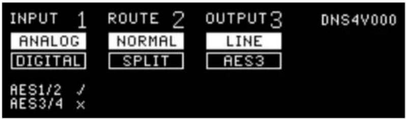
Pressing Setup a second time takes you to the Global setup page. There are three parameters, each of which has two possible settings.
Inputs
Select the analogue or digital inputs. If the input selection is set to digital and no valid digital signal is present at the digital input, a flashing cross will appear inside the AES1/2 or AES3/4 fields and the DNS 4 will not process audio.
■ Routing: Split mode operation
In split mode, the signals presented to inputs 1&2 are duplicated and sent to channels 3&4. This allows inputs 1&2 to be processed and output in two different ways, including outputting the duplicate pair without processing to create 'iso' tracks.
■ Outputs 3 & 4: analogue line or AES3 digital
Select whether outputs 3&4 carry line level analogue or digital signals. The input/output selections operate as follows:
| Input | Output | Output 1 | Output 2 | Output 3 | Output 4 | |
| 1 | Analogue | Analogue | Line 1 | Line 2 | Line 3 | Line 4 |
| 2 | Analogue | Digital | Line 1 | Line 2 | AES 3 1&2 | AES 3 3&4 |
| 3 | Digital | Analogue | Line 1 | Line 2 | Line 3 | Line 4 |
| 4 | Digital | Digital | - | - | AES 3 1&2 | AES 3 3&4 |
Principal uses:
1: integrates the DNS 4 into an analogue system
2: allows the DNS 4 to be used as a mic pre as well as a processor within an otherwise digital system
3: allows you to output analogue signals from a digital system
4: is digital-to-digital and all the analogue I/O is switched off to save power.
Press setup again or wait for the timeout to return to the Process screen.
Using the DNS 4
Processing
When you are in the Process page, pressing any of the row of four channel access buttons at the top right of the unit brings its associated channel into focus. Once a given channel has focus, its associated button is lit and you can adjust its parameters. Channels can also be grouped and their parameters adjusted together.
The process is controlled by an encoder plus dedicated buttons for process on/off and learn on/off. Normally the encoder is focused upon the Attenuation parameter. Clicking it switches its focus to the Bias parameter, and a second click returns it to the Attenuation. The encoder focus also reverts to Attenuation after a short timeout.
■ Process On/Off
Use the dns on button to switch the DNS processing on and off.
Learn
The Learn button controls whether or not the noise detector adapts continuously to changes in the noise content within the audio signal. When it’s On, the DNS 4 continually identifies the power and spectral distribution of the noise. When it’s Off, the noise estimate is frozen at the last determined values and remains so until it’s switched on again.
Note: Learn is not a method for taking a ‘noise fingerprint’ and, for most jobs, by far the best results are obtained by leaving it switched on permanently.
Channel selection
Before adjusting anything further, use the channel selector buttons 1-4 to select the individual channel or, if linked, the group of channels that you wish to control.
The process parameters
Attenuation
The default action of the encoder is to adjust the amount of noise attenuation applied to the signal in the selected channel(s). The representation of the left-hand fader within each channel shows the current position of the control, and the bargraph shows the instantaneous amount of attenuation being applied to the signal. The solid bar shows the average attenuation across all frequencies, and the shaded bar shows the maximum attenuation across all frequencies.
Bias
The encoder also provides control of the Bias, which is shown on the right-hand half of each channel's display. Click the encoder to enable adjustment of the Bias, and click it again when you wish to switch back to controlling the Attenuation. The encoder will also revert to controlling the Attenuation after a short idle period.
The Bias is a ‘center-zero’ control, and the fader shows the current position. Raise the Bias to bias the algorithm toward detecting more noise. This will allow the process to remove more noise, but may lead to compression of the wanted audio and make the signal sound dry. Lower the Bias to bias the algorithm toward detecting less noise. This will allow the process to retain more ‘atmos’, but may allow noise to leak back into the wanted signal. In most cases, the optimum value for the Bias is the central, zero point.
The right-hand bargraph shows the detected signal to noise ratio (SNR). The solid bar shows the noise level, and the shaded bar shows the signal level; consequently, the difference between the heights of the solid and shaded bars indicates the SNR. You can see the affect of altering the Bias reflected in the height of the solid bar, which tends to increase as you raise the Bias, and vice-versa.
Summary of operation
Learn
When Learn is on, the DNS 4 continually identifies the power and spectral distribution of the noise present. This is the normal mode of operation.
When Learn is off, the noise identification is frozen at the last determined values.
Bias
This influences the amount of noise detected by Learn. You can bias the detection upward (more noise detected) or downward (less noise detected).
Attenuation
This determines how much noise will be removed from the signal.
In short
- Learn and Bias determine what is detected as noise.
• Attenuation determines how much of the detected noise is suppressed.
The display
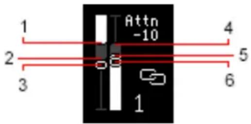
① The average attenuation being applied across all frequencies
② The maximum attenuation being applied at some frequency
③ The current position of the Atten control
④ The detected signal level
⑤ The detected noise level
⑥ The current position of the Bias control
Additional information
Intentionally left blank
Declaration of conformity
Date of issue 1 September 2022
Equipment CEDAR DNS 4
Manufacturer CEDAR Audio Ltd
Address 20 Home End, Fulbourn, Cambridge CB21 5BS, UK
This is to certify that the aforementioned equipment, when used in accordance with the instructions in this manual, fully conforms to the protection requirements of the following EC Council Directives: on the approximation of the laws of the member states relating to:
2004/108/EEC Electromagnetic Compatibility Directive
Applicable standards: EN 55032-2015
EN 55035 - 2017
2006/95/EC Low Voltage Directive
Applicable standard: EN 62368-1-2014+A11-2017
■ Restriction of Hazardous Substances (RoHS) Directive
All hardware products and sub-assemblies manufactured by CEDAR Audio Ltd are designed to be compliant with Directive 2015/863/EU, Restriction of Hazardous Substances. The manufacturing processes include the assembly of purchased components and/or sub-assemblies from various sources. Any statement of RoHS compliance made by CEDAR Audio Ltd may be based, in part or in full, on statements provided by suppliers. Thus whilst every effort is made to ensure compliance, CEDAR Audio Ltd may not have undertaken independent tests to establish the compliance of such components and/or sub-assemblies.
■ Waste Electrical and Electronic Equipment (WEEE) Directive
In accordance with Directive 2002/96/EC, Waste Electrical and Electronic Equipment, CEDAR Audio Ltd will provide its customers with information about local organisations that can reprocess CEDAR products that have reached their end of use. Alternatively such products can be returned to CEDAR Audio Ltd in the UK at the owner's cost and they will then be reprocessed correctly free of charge.
3rd-party Licence
The CEDAR DNS 4 firmware includes certain elements that are distributed under the following licence.
=== FreeRTOS LICENSE ===
Copyright (C) 2017 Amazon.com, Inc. or its affiliates. All Rights Reserved.
Permission is hereby granted, free of charge, to any person obtaining a copy of this software and associated documentation files (the "Software"), to deal in the Software without restriction, including without limitation the rights to use, copy, modify, merge, publish, distribute, sublicense, and/or sell copies of the Software, and to permit persons to whom the Software is furnished to do so, subject to the following conditions:
The above copyright notice and this permission notice shall be included in all copies or substantial portions of the Software. If you wish to use our Amazon FreeRTOS name, please do so in a fair use way that does not cause confusion.
THE SOFTWARE IS PROVIDED "AS IS", WITHOUT WARRANTY OF ANY KIND, EXPRESS OR IMPLIED, INCLUDING BUT NOT LIMITED TO THE WARRANTIES OF MERCHANTABILITY, FITNESS FOR A PARTICULAR PURPOSE AND NONINFRINGEMENT. IN NO EVENT SHALL THE AUTHORS OR COPYRIGHT HOLDERS BE LIABLE FOR ANY CLAIM,
DAMAGES OR OTHER LIABILITY, WHETHER IN AN ACTION OF CONTRACT, TORT OR OTHERWISE, ARISING FROM, OUT OF OR IN CONNECTION WITH THE SOFTWARE OR THE USE OR OTHER DEALINGS IN THE SOFTWARE.
Contact information
Headquarters:
CEDAR Audio Ltd,
20 Home End, Fulbourn, Cambridge, CB21 5BS, United Kingdom
t: +44 1223 881771
e: support@cedaraudio.com
USA Office:
CEDAR Audio USA
82 Gilman Street, Portland, ME 04102, USA
t: +1 207 828 0024
e: cedarusa@cedaraudio.com
German Office:
CEDAR Deutschland
Balanced TA3 mini-XLR
Impedance: 10kΩ
Nominal signal level (0dB gain): +4dBu
ADC line up (0dB gain): +4dBu : -20dBFS
Clipping level (0dB gain): +24dBu
Dynamic range (0dB gain):
102dB (AES17 unweighted)
Gain range: 0dB to +20dB
Microphone inputs
Connector:
Balanced XLR3F
Impedance: 2kΩ
Gain range: 18dB to 78dB
ADC line up (36dB gain): -32dBu : -20dBFS
Dynamic range (36dB gain):
102dB (AES17 unweighted)
Phantom Power
Type:
P48 (IEC61958)
Unloaded voltage: +48V ± 4V
Current available:
10mA per microphone
Short circuit protection: Indefinite
AD/DA conversion
Resolution:
24-bit linear PCM
Sample rate (internal sync):
48kHz
Sample rate (external sync):
40kHz - 100kHz
Digital inputs
Connector: Balanced TA3 mini-XLR
Format:
AES3 (IEC60958) or AES11 (DARS)
Sample rate sync ranges:
Connector: Balanced TA3 mini-XLR
Nominal signal level: +4dBu
DAC line up: -20dBFS : +4dBu
Maximum output: +24dBu
Dynamic range: >96dB (AES17 unweighted)
Minimum load impedance: 600Ω
Short circuit protection: Indefinite
Digital outputs
Connector: Balanced TA3 mini-XLR
Format: AES3 (IEC60958)
Sample rate (internal sync): 48kHz (±50ppm)
Sample rate (external sync): locked to digital input
DSP
Type: Floating point
Resolution: 40-bit
Sample rates: 44.1kHz, 48kHz, 96kHz
Latency: <4ms in all modes
Power input
Voltage: 8V to 17.5V (nominal 12V)
Connector: Hirose 4-pin HR10 (pin1 -, pin4 +)
Reverse polarity protection: Indefinite
Over-voltage protection: Indefinite, up to 50V
Max power consumption @ 12V: 10W
Power adapter
Input voltage: 85VAC - 260VAC, 50 - 60Hz
Input power: 15W
Input connector: UK/US/EU
Output voltage: 12V
Output connector: Hirose 4-pin HR10 (pin1 -, pin4 +)
E&OE
The Company reserves the right to change specifications without notice.
Licence and limited warranty
1. DEFINITIONS
In this Licence and Limited Warranty the following words and phrases shall bear the following meanings:
'the Company' is CEDAR Audio Limited of 20 Home End, Fulbourn, Cambridge CB21 5BS, UK;
'a/the System' means an instance of the DNS 4 sound processing system comprising hardware and software developed by the Company;
'this Document' means this Licence and Limited Warranty.
2. ISSUE AND USE OF THE SYSTEM
3. PROPERTY AND CONFIDENTIALITY
4. LIMITED WARRANTY AND POST-WARRANTY OBLIGATIONS
2.1 The terms and conditions of this Document are implicitly accepted by any person or body corporate who shall at any time use or have access to the System, and are effective from the date of supply of the System by CEDAR Audio Limited to its immediate customer.
2.2 The Company hereby grants to the Licensee and the Licensee agrees to accept a non-exclusive right to use the System.
3.1 The System contains confidential information of the Company and all copyright, trade marks, trade names, styles and logos and (excluding such IP owned by Audinate or covered by the attached 3rd-party licences or is in the public domain) all other intellectual property rights in the System and the documentation and manuals relating thereto are the exclusive property of the Company. The Licensee acknowledges that all such rights are the property of their respective owners and shall not question or dispute the ownership of any such rights nor use or adopt any trading name or style similar to that of the Company or any other relevant parties.
3.2 Unless explicitly permitted in writing by the relevant intellectual property owner, the Licensee shall not attempt to reverse engineer, modify, copy, merge or transcribe the whole or any part of the System or any information or documentation relating thereto.
3.3 The Licensee shall take all reasonable steps to protect the confidential information and intellectual property rights of the Company and other owners of intellectual property in the System.
4.1 The Company warrants that a System will perform substantially in accordance with the appropriate section of its accompanying product manual for a period of one year from the date of supply to the Company's immediate customer.
4.2 The Company will make good at its own expenses by repair or replacement any defect or failure that develops in a System within one year of supply to the Company's immediate customer.
4.3 The Company shall have no liability to remedy any defect, failure, error or malfunction that arises as a result of any improper use, operation or neglect of a System, or any attempt to repair or modify a System by any person other than the Company or a person appointed with the Company's prior written consent.
4.4 In the case of any defect or failure in a System occurring more than twelve months after its supply to the Company's immediate customer the Company will at its option and for a reasonable fee make good such defect or failure by repair or replacement (at the option of the Company) subject to the faulty equipment having first been returned to the Company. The Company will use reasonable efforts to return repaired or replacement items promptly, all shipping, handling and insurance costs being for the account of the Licensee.
4.5 The above undertakings 4.1 to 4.4 are accepted by the Licensee in lieu of any other legal remedy in respect of any defect or failure occurring during the said period and of any other obligations or warranties expressed or implied including but not limited to the implied warranties of saleability and fitness for a specific purpose.
4.6 The Licensee hereby acknowledges and accepts that nothing in this Document shall impose upon the Company any obligation to repair or replace any item after a time when it is no longer produced or offered for supply by the Company or which the Company certifies has been superseded by a later version or has become obsolete.
5. FORCE MAJEURE
The Company shall not be liable for any breach of its obligations hereunder resulting from causes beyond its reasonable control including, but not limited to, fires, strikes (of its own or other employees), insurrection or riots, embargoes, container shortages, wrecks or delays in transportation, inability to obtain supplies and raw materials, or requirements or regulations of any civil or military authority.
6. WAIVER
The waiver by either party of a breach of the provisions hereof by the other shall not be construed as a waiver of any succeeding breach of the same or other provisions, nor shall any delay or omission on the part of either party to exercise any right that it may have under this Licence operate as a waiver of any breach or default by the other party.
7. NOTICES
Any notices or instruction to be given hereunder shall be sent by first-class post or email to the other party, and shall be deemed to have been served upon the expiration of seven days after posting or (if sent electronically) upon the expiration of twelve hours after transmission.
8. ASSIGNMENT AND SUB-LICENSING
The Licensee may at his discretion assign a System and in doing so shall assign this License its rights and obligations to the purchaser who shall without reservation agree to be bound by this License. The original Licensee and any subsequent Licensees shall be bound by the obligations of this License in perpetuity.
9. LIMITATION OF LIABILITY
The Company's maximum liability under any claim including any claim in respect of infringement of the intellectual property rights of any third party shall be, at the option of the Company either:
• return of a sum calculated as the price received for the System by the Company from its immediate customer depreciated on a straight line basis over a one year write-off period; or
- repair or replacement of those components of the System that do not meet the warranties contained within this Document.
The foregoing states the entire liability of the Company to the Licensee.
10. CONSEQUENTIAL LOSS
Even if the Company has been advised of the possibility of such damages, and notwithstanding anything else contained herein the Company shall under no event be liable to the Licensee or to any other persons for loss of profits or contracts or damage (whether direct or consequential) arising in connection with a System or any modification, variation or enhancement thereof and including any documentation or data provided by the Company or for any other indirect or consequential loss.
11. ENTIRE AGREEMENT
The Company shall not be liable to the Licensee for any loss arising in connection with any representations, agreements, statements or undertakings made prior to the date of supply of the System to the Licensee.
12. TERMINATION
This Licence may be terminated forthwith by the Company if the Licensee commits any material breach of any terms of this License. Forthwith upon such termination the Company shall have immediate right of access to the System for the purpose of removing it.
13. SEVERABILITY
Notwithstanding that the whole or any part of any provision of this Document may prove to be illegal or unenforceable the other provisions of this Document and the remainder of the provision in question shall remain in full force and effect.
14. HEADINGS
The headings to the Clauses are for ease of reference only and shall not affect the interpretation or construction of this Document.
15. LAW
This Document shall be governed by and construed in accordance with English law and all disputes between the parties shall be determined in England in accordance with the Arbitration Act 1950 and 1979.
CEDAR dns 4
| Inspected: | |
| QC Engineer: | |
| Serial number: |
Designed and manufactured by
CEDAR Audio Ltd
20 Home End
Fulbourn
Cambridge CB21 5BS
United Kingdom
www.cedaraudio.com
info@cedaraudio.com
t: +44 1223 881771
Copyright CEDAR Audio Ltd, © 2022
CEDAR is a registered trademark of CEDAR Audio Ltd
DNS, DNS One, DNS 8D, DNS 8 Live, DNS 8 CS, DNS One, DNS Two, DNS 2, DNS 4, DNS1000, DNS1500, DNS2000 and DNS3000 are trademarks of CEDAR Audio Ltd
E&OE, Subject to revision at the Company's sole discretion
- DNS 4 dialogue noise suppressor
- Table of Contents
- Introduction to the DNS 4
- Near zero latency
- Flexibility
- ■ Speed and ease of use
- 12VDC power
- ■ Powerful processors
- Safety instructions
- Water and moisture
- ■ Mounting and ventilation
- Power sources
- Connections
- Cleaning
- ■ Damage requiring service
- Setting up the DNS 4
- Unpacking
- Power source
- Audio setup
- Inputs
- ■ Outputs
- Audio clock
- USB
- The front panel
- Pages
- Process
- Channel setup
- Global setup
- Fixed-function buttons
- Power/lock
- Setup
- Bypass
- Short press
- Long press
- The process page
- ■ Input level meters
- ■ Process readouts
- Channel linking
- The channel setup page
- ■ Digital inputs selected (see Global setup)
- ■ Analogue inputs selected (see Global setup)
- ■ High-pass filter
- The global setup page
- ■ Routing: Split mode operation
- ■ Outputs 3 & 4: analogue line or AES3 digital
- Principal uses:
- Using the DNS 4
- Processing
- ■ Process On/Off
- Learn
- Channel selection
- The process parameters
- Attenuation
- Bias
- Summary of operation
- In short
- The display
- Additional information
- Declaration of conformity
- ■ Restriction of Hazardous Substances (RoHS) Directive
- ■ Waste Electrical and Electronic Equipment (WEEE) Directive
- 3rd-party Licence
- Contact information
- Headquarters:
- USA Office:
- German Office:
- Microphone inputs
- Phantom Power
- AD/DA conversion
- Digital inputs
- Digital outputs
- DSP
- Power input
- Power adapter
- E&OE
- Licence and limited warranty
- DEFINITIONS
- ISSUE AND USE OF THE SYSTEM
- PROPERTY AND CONFIDENTIALITY
- LIMITED WARRANTY AND POST-WARRANTY OBLIGATIONS
- FORCE MAJEURE
- WAIVER
- NOTICES
- ASSIGNMENT AND SUB-LICENSING
- LIMITATION OF LIABILITY
- CONSEQUENTIAL LOSS
- ENTIRE AGREEMENT
- TERMINATION
- SEVERABILITY
- HEADINGS
- LAW
- CEDAR dns 4
Brand : CEDAR
Model : DNS 4
Category : Processor