
500072 - Computer accessory MuxLab - Free user manual and instructions
Find the device manual for free 500072 MuxLab in PDF.


| Product Type | USB 2.0 Extender Kit (4-Port) |
| Model Number | 500072 |
| Transmitter Connectors | 1 x USB Type B Female (input), 1 x RJ-45 Female (output) |
| Receiver Connectors | 1 x RJ-45 Female (input), 4 x USB Type A Female (output) |
| Interconnection Cable | Standard Cat5e/6 |
| Maximum Cable Length | 100 m (328 ft) |
| Data Rate | Up to 480 Mbps (USB 2.0 High-Speed) |
| USB Support | USB 2.0 High-Speed, USB 1.1 (Low-Speed, Full-Speed); Control, Interrupt, Bulk, Isochronous |
| Operating Systems | Windows 2000/XP/Vista/7/8/8.1, Mac OS, Linux |
| LED Indicators | Power (Red) and Link (Orange) on both units |
| Power Supply | 5 VDC, 2 A (included adapter) |
| USB Cable Included | 0.6 m USB 2.0 Type A/M to Type B/M |
| Housing Material | Aluminum |
| Dimensions (L x W x H) | 90 x 73 x 31 mm (3.5 x 2.9 x 1.2 in) |
| Mounting | Wall-mountable (enclosure design) |
| Package Contents | 1 transmitter, 1 receiver, 1 power adapter, 1 USB cable |
| Wiring Standard | Recommended T568B |
| Regulatory Compliance | CE, FCC Class B, RoHS, WEEE |
Frequently Asked Questions - 500072 MuxLab
User questions about 500072 MuxLab
0 question about this device. Answer the ones you know or ask your own.
Ask a new question about this device
Download the instructions for your Computer accessory in PDF format for free! Find your manual 500072 - MuxLab and take your electronic device back in hand. On this page are published all the documents necessary for the use of your device. 500072 by MuxLab.
USER MANUAL 500072 MuxLab
- Introduction......2
- Features....2
- Specifications....2
- Package Contents .... 3
- Physical Diagram....3
- Installation....5
- Category cable wiring....6
- Troubleshooting....7
- Regulatory Compliance 8
1. Introduction
The USB 2.0 high speed extender system enables USB 2.0 connectivity over Cat5e/6 at data rates up to 480Mbps and extends true USB up to 100m (328ft) over standard Cat5 twisted pair cable. This unit is true plug and play, requires no additional software drivers, and is compatible with all major operating systems such as Windows, Mac and Linux.
It is ideal for accessing remotely laser printers, scanners, web cameras, external hard drives, CD/DVD burners, and flash drives. It supports a wide variety of USB extension applications including security, industrial control, digital signage, scientific data acquisition and other implementations of USB standards.
2. Features
■ True plug and play, no driver installation required.
■ Extends USB 2.0 high-speed and USB 1.1 (low-speed, full-speed) devices up to 100m (328ft) over Cat. 5e/6 cable
■ Supports all USB device types: Control, Interrupt, Bulk and Isochronous at up to 480Mbps
■ Ideal for a wide variety of USB devices, printers, scanners, hard drives, audio devices, touch screens, web cams, and game controllers.
■ Compatible with major operating systems: Windows 2000 / XP / Vista / 7 / 8 / 8.1, Mac OS, Linux or higher
■ Aluminum enclosure and wall mountable
3. Specifications
| Model No. | 500072 | ||
| Transmitter | Receiver | ||
| Connector | Upstream / Input | USB B Female | RJ-45 Female |
| Output / Downstream | RJ-45 Female | USB Type A Female x 4 | |
| Interconnection Cable | Standard Cat. 5e/6 | ||
| Max. Cable Length | 100m (328ft) | ||
| LED | 2 | ||
| USB Cable Length | 0.6m (USB Type A/M to Type B/M) | ||
| Power Supply | 5VDC 2A | ||
| Housing | Aluminum | ||
| Dimension ( L x W x H ) | 90 x 73 x 31mm | ||
4. Package Contents
■ One (1) Transmitter unit
■ One (1) Receiver unit
■ One (1) 5VDC Power adapters
■ One (1) USB 2.0 Type A/M to Type B/M Cable 0.6m
5. Physical Diagram
5.1 Transmitter (Local Unit)
Top View

Front view

RJ45 Link port to connect to the Cat.5 cabling
Side view
Link Led indicates a valid link between the Tx and the Rx via Cat.5 cabling

Power Led indicates that the power is connected
Rear view
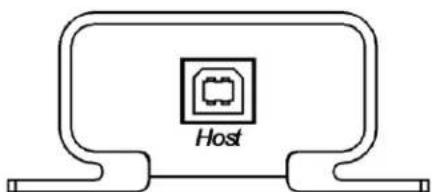
Host Port is using USB Type B interface
5.2 Receiver (Remote Unit)
Top View
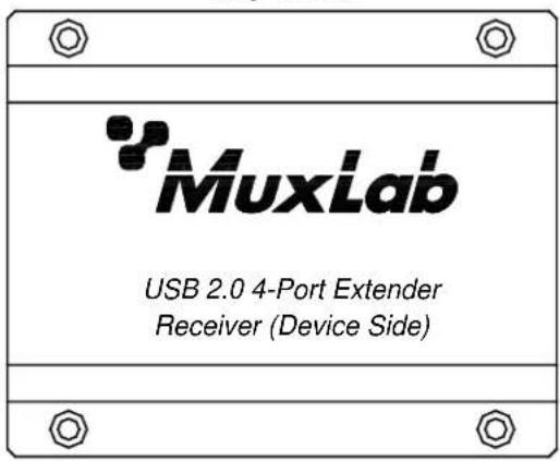
RJ45 Link port to connect to the Cat.5 cabling

Power port connects to the 5VDC-2A power supply
Link Led indicates a valid link between the Tx and the Rx via Cat.5 cabling

Power Led indicates that the power is connected

Ports 1 to 4 are USB Device Ports using USB Type A interface.
6. Installation
6.1 Typical Application

6.2 Installing the Transmitter and the Receiver
6.2.1. Preparing for Installation
Follow these steps to prepare your installation:
- Determine where the host computer will be located and set up the computer.
- Determine where you want to locate the remote USB device(s).
- The extender supports a maximum distance or 328 ft (100m). Make sure that Cat5 cabling is installed, with Cat. 5 outlets located near both computer and USB devices. The total length of this cable, including patch cords, must not be longer than 328 ft (100m).
6.2.2. Installing the Transmitter (Local Unit)
- Plug the supplied USB cable into the transmitter and connect to an available USB port of computer.
- Plug one end of the Cat. 5 cable into the Link port (RJ-45) on the transmitter. (Please see Category cable wiring).
6.2.3. Installing the Receiver (Remote Unit)
- Plug the other end of the Cat. 5 cable into the Link port (RJ-45) on the receiver.
- Plug the 5VDC, 2A power adapter into the receiver, and AC plug into the power receptacle.
- The Red Power LED indicator lights on the Transmitter and Receiver.
- Connect the USB devices through USB cables into the Receiver's USB ports labeled 1 to 4 on receiver.
| LED | Status | |
| Definition | Color | |
| Power | Red | Indicates that the 5VDC power adapter is plugged in. |
| Link | Orange | Indicates that the USB ports are plugged in. |
6.3 Checking the Installation
- Check the Link (Orange) LED indicators light on both the transmitter and the receiver.
- For Windows users (2000, XP, Vista, 7, 8, and 8.1), open Device Manager to confirm the extender has been installed correctly. Expand the Entry and check the USB controllers. If the extender is installed correctly, it should be listed as a "Generic USB Hub."
- For Mac OS X users, open the System Profiler to confirm that the extender has been installed correctly. In the left column under Hardware, select "USB" and check the right panel. If the extender has been installed correctly, you should find it listed as a "Hub" under the USB High-Speed Bus/USB Bus.
- If the extender is not detected correctly or fails to detect, go to the Troubleshooting section of this manual.
7. Category cable wiring
Take precaution selecting the Cat. 5 wires before connecting; use a cable tester to check the wires are correctly terminated. (Incorrect Termination may cause damage to the receiver unit). Recommend to use T568B wiring as shown.
T568B Wiring

8. Troubleshooting
The following table describes some of the symptoms, probable causes and possible solutions in respect to the installation of the USB 2.0 4-Port Extender kit.
Table -1 Troubleshooting tips
| Problem | Cause | Solution |
| The USB device is attached but not functioning. | · The USB device requires drivers that were not installed.· The USB device does not support USB hubs.· The USB device might be failed. | 1. Install the required USB device driver on the computer operating system before plug in the USB device to the receiver. Access your USB device's manufacturer's Web site for detail info.2. In the Universal Serial Bus (USB) controllers section of Device Manager, check if the USB device is listed. |
| The USB device is attached but not functioning. | · An over current condition has occurred because the USB device is drawing more than 500mA (USB spec.). The operating systems may pop up to indicate an issue. | 1. Unplug the power adapter from the receiver, wait approximately 30 seconds; plug the power adapter into receiver again.2. If over current keeps occurring, either the USB device may use more power than the USB specification, or the USB device may be damaged.3. Consult your USB device documentation and plug into your USB device with the required power adapter. |
| Power LED on transmitter is off. | · The Cat. 5 cable connecting the transmitter and receiver is faulty. | 1. Make sure the Cat.5 cable is good.2. Try to use a different Cat.5 cable to connect transmitter and receiver.3. Check power adapter on the receiver |
| Power LED on transmitter and receiver is off. | · The receiver is not powered.· The transmitter is not powered.· The link cable failed or is damaged.· The extender is not working. | 1. Confirm that the host PC is on and providing power to the transmitter.2. Make sure the supplied AC power adapter is properly connected to the receiver.3. Make sure the Cat5 cabling between transmitter and receiver is properly installed or replace the link cable.4. Check that the power adapter is connected and working. |
If you still cannot diagnose the problem, please call MuxLab Customer Technical Support at 877-689-5228 (toll-free in North America) or (+1) 514-905-0588 (International).
Regulatory Compliance
Disclaimer
Information in this document is subject to change without notice. The manufacturer does not make any representations or warranties (implied or otherwise) regarding the accuracy and completeness of this document and shall in no event be liable for any loss of profit or any other commercial damage, including but not limited to special, incidental, consequential, or other damages.
No part of this document may be reproduced or transmitted in any form by any means, electronic or mechanical, including photocopying, recording or information recording and retrieval systems without the express written permission of the manufacturer.
All brand names and product names used in this document are trademarks, or registered trademarks of their respective holders.
CE/FCC & Recycling Information
CE Certification
This equipment complies with the requirements relating to Electromagnetic Compatibility Standards EN55022/EN55024 and the further Standards cited therein. It must be used with shielded cables only. It has been manufactured under the scope of RoHS compliance.
FCC Certification
This equipment has been tested and found to comply with the limits for a Class B digital device, pursuant to part 15 of the FCC Rules. These limits are designed to provide reasonable protection against harmful interference in a residential installation. You are cautioned that changes or modification not expressly approved by the party responsible for compliance could void your authority to operate the equipment.
This device complies with part 15 of the FCC Rules.
Operation is subject to the following two conditions:
-
This device may not cause harmful interference, and
-
This device must accept any interference received, including interference that may cause undesired operation

WEEE (Waste of Electrical and Electronic Equipment), Recycling of Electronic Products
In 2006 the European Union introduced regulations (WEEE) for the collection and recycling of all waste electrical and electronic equipment. It is no longer allowable to simply throw away electrical and electronic equipment. Instead, these products must enter the recycling process.
Each individual EU member state has implemented the WEEE regulations into national law in slightly different ways. Please follow your national law when you want to dispose of any electrical or electronic products. More details can be obtained from your national WEEE recycling agency.
CEFC

2321 Rue Cohen, Montreal, Quebec, Canada. H4R 2N7
Tel: (514) 905-0588
Fax: (514) 905-0589
Toll Free (North America): (877) 689-5228
E-mail: info@muxlab.com
URL: www.muxlab.com
- Introduction
- Features
- Specifications
- Package Contents
- Physical Diagram
- Transmitter (Local Unit)
- Receiver (Remote Unit)
- Installation
- Typical Application
- Installing the Transmitter and the Receiver
- Preparing for Installation
- Installing the Transmitter (Local Unit)
- Installing the Receiver (Remote Unit)
- Checking the Installation
- Category cable wiring
- Troubleshooting
- Regulatory Compliance
- Disclaimer
- CE/FCC & Recycling Information
- CE Certification
- FCC Certification
- WEEE (Waste of Electrical and Electronic Equipment), Recycling of Electronic Products
Brand : MuxLab
Model : 500072
Category : Computer accessory