D48E - Camera FLIR - Free user manual and instructions
Find the device manual for free D48E FLIR in PDF.

| Product Type | Thermal Imaging Camera |
| Brand | FLIR |
| Model | D48E |
| Dimensions | 250 x 95 x 85 mm (approx) |
| Weight | 0.6 kg (approx) |
| Power Source | Rechargeable Li-Ion battery (7.4V, 3.5Ah) |
| Battery Life | Up to 4 hours continuous operation |
| Display | 3.5-inch LCD touchscreen (320x240) |
| Thermal Resolution | 160x120 pixels |
| Temperature Range | -20°C to 400°C |
| Accuracy | ±2°C or ±2% of reading |
| Spectral Range | 7.5-13 µm |
| Image Frequency | 9 Hz |
| Focus | Fixed focus |
| Storage | microSD card (up to 32GB) |
| Connectivity | USB-C, Wi-Fi (optional) |
| Main Functions | Thermal imaging, image capture, video recording, temperature measurement, spot metering, area analysis |
| Maintenance | Clean lens with soft cloth, avoid moisture |
| Safety | Do not point at intense heat sources, avoid water immersion |
| Spare Parts | Battery, charger, carrying case, lens cap |
| Repairability | Not user-serviceable; contact FLIR service center |
| General Information | User manual available for download; warranty 2 years |
Frequently Asked Questions - D48E FLIR
User questions about D48E FLIR
0 question about this device. Answer the ones you know or ask your own.
Ask a new question about this device
Download the instructions for your Camera in PDF format for free! Find your manual D48E - FLIR and take your electronic device back in hand. On this page are published all the documents necessary for the use of your device. D48E by FLIR.
USER MANUAL D48E FLIR
REVISION DATE: January, 2011
User Manual
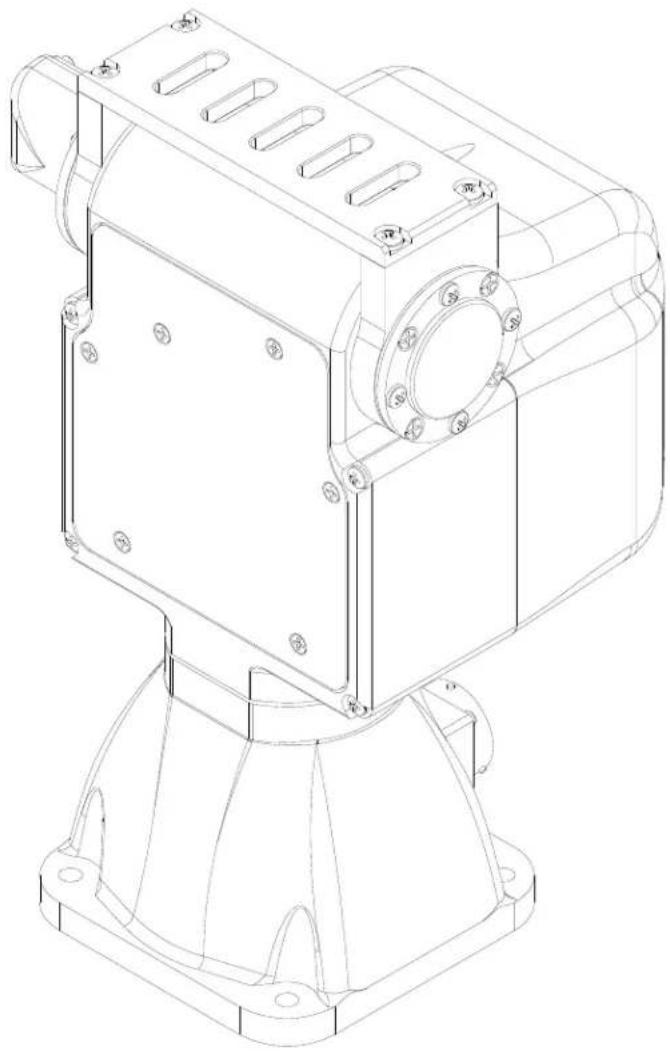
natural_image
Technical line drawing of a mechanical housing component with mounting flanges and bolt holes (no text or symbols)DOCUMENT CONTROL
| Date | Author | Rev. # | Changes |
| 09/2010 | A. Hernandez | 4.00 | Initial E Series doc release |
| 09/2010 | A. Hernandez | 4.10 | Added cable diagram, minor fixes |
| 01/2011 | A. Hernandez | 4.20 | Added ISM information |

Note: This manual describes the E Series PTU-D48 only. If you have any other series of PTU-D48, please refer to the appropriate documentation for that series.
COPYRIGHT NOTICE
Pan-Tilt Unit (Model PTU-D48 E Series) User's Manual
©1991, 2010 by FLIR Motion Control Systems, Inc., 890C Cowan Road, Burlingame, California 94010, (650)692-3900, FAX: (650)692-3930, www.FLIR.com./MCS
All rights reserved. Protected under numerous U.S. patents, including 5463432 and 5802412 with other patents pending. No part of this book may be reproduced, stored in a retrieval system, or transcribed in any form or by any means including but not limited to electronic, mechanical, photocopying, recording, or otherwise, without the prior written permission of FLIR Motion Control Systems, Inc.
The information in this manual is subject to change without notice and, except for the warranty, does not represent a commitment on the part of FLIR Motion Control Systems, Inc. FLIR Motion Control Systems, Inc. cannot be held liable for any mistakes in this manual and reserves the right to make changes.
Table of Contents
1 - Introduction .... 1
1.1 – General PTU-D48 Features .... 1
1.2 – E Series Features.... 2
1.3 – Applications ...... 2
1.4 – About This Manual.... 3
1.4.1 – Formatting Conventions.... 3
1.5 – Models 4
1.6 – PTU-D48 Package Contents 4
1.7 – Related Documentation.... 5
1.8 – Additional Resources .... 5
1.9 – Technical Support .... 5
2 – Safety ....7
2.1 – Safety Warnings and Cautions....7
3 – Quick Start....9
3.1 – System Overview 9
3.2 – Installation Components .... 10
3.3 – Basic Setup.... 10
3.4 – Ethernet Connection.... 11
3.5 – Serial Connection.... 13
4 – Installation and Setup....15
4.1 – Mounting the Unit 15
4.2 – Wiring and Connectors 16
4.2.1 – Mechanical Overview.... 16
4.2.2 – Wiring Options 17
4.3 – Power Sources 17
4.4 – Fusing.... 18
4.5 – Shielding.... 18
4.6 – Interface and Host Settings 18
4.6.1 – Ethernet Connection....18
4.6.2 - RS-232 Electrical Connection 19
4.6.3 - RS-485 Electrical Connection 19
4.7 – Initial Power-Up and Test 20
4.7.1 – Web Interface 20
4.7.2 - Terminal Interface 20
4.8 – Payload Mounting.... 21
4.8.1 - Side Bracket Attachment 21
4.8.2 - Payload Attachment.... 22
4.9 – Payload Wiring Connector (Optional) 24
5 – Configuring & Programming ....25
5.1 – Range of Motion 25
5.1.1 – Default Limits ...... 26
5.2 – Resolution and Step Modes.... 27
5.3 – User-Programmable Settings.... 27
5.3.1 – High-Speed Operation....27
5.3.2 - Heavy-Payload Operation 28
5.3.3 – Battery Powered Operation 29
6 – Web Interface....31
6.1 – PTU Configuration Page 31
6.2 – Network Page 34
6.3 – PTU Control Page 35
A. - Electrical Specifications ....37
A.1-32-Pin Base Connector 38
A.2 - 19-Pin Payload Connector 39
A.3 – PL01 Wiring Diagram 40
A.4 – PL02 Wiring Diagram 41
A.5-32-Pin Breakout Cable 42
B. – Mechanical Drawings......43
B.1 – Payload Mounting Pattern.... 44
B.2 – PTU-D48 Dimensions (Standard) 46
B.2 - PTU-D48 Dimensions (ISM)...... 47
C. - Networking....49
C.1 – Ethernet 49
C.2 - Serial.... 49
C.2.1 – Serial Networking Connections.... 50
C.2.2 – ASCII Command Syntax 51
C.2.3 – Serial Command List....52
D. -Troubleshooting ....53
D.1-Mechanical 53
D.2 - Power.... 53
D.3 – Networking 53
D.4 – Technical Support 54
E. – Regulatory Information ....57
Class A 57
FCC Notice....57
CE Notice....57
Table of Figures
Figure 1: Pan-Tilt System Overview....9
Figure 2: Hole Mounting Pattern....15
Figure 3: Bracketing Options....21
Figure 4: Pan-Tilt Default Factory Limits....26
Figure 5: PTU Network Configuration....50
This page intentionally left blank.
1 - Introduction
The PTU-D48 E Series Pan-Tilt Unit (PTU-D48) from FLIR Motion Control Systems provides fast, accurate, and durable positioning of cameras, antennas, lasers, and other payloads. This User Manual contains setup, general configuration, wiring, and mechanical interface information that is intended for use by design engineers and integrators who are configuring, installing, and programming the PTU-D48. Please see 1.7 for a list of other documents related to the PTU-D48.

Note: This manual describes setting up and using the PTU-D48 E Series unit. Optional modules are not included in these instructions. If your PTU-D48 includes any optional modules, please refer to the documentation included with those modules for help with their setup and use.
1.1 - General PTU-D48 Features
The PTU-D48 series offers the following general features:
- Serial communication capability via terminal or computer
- Payload capacity of 10lbs (top mount) or 15lbs (side mount)
• Pan resolution of 0.006°
• Tilt resolution of 0.003° - Precise position, speed & acceleration control
- On-the-fly position and speed changes
• Self-calibration on reset with reduced motion
• Host-controllable power consumption
• Simple ASCII command mode
• High-speed binary command interface - Constant-current motor drives for increased performance and control
• Unregulated 12-30 VDC power input
• Flexible connectivity options
• Sealed for outdoor operation (IP67) - Slip ring for continuous 360° pan operation (optional).
Please refer to the PTU-D48 E Series Product Datasheet for complete specifications.
1.2 - E Series Features
The PTU-D48 E Series includes the following new features:
• Built-in Ethernet/Web IP interface for easy configuration, control, and diagnostics
- Improved power protection circuitry
• 32-pin base connector for simplified wiring
- Integrated digital encoder for more robust positioning
• Programmable ranges of motion
• Higher command rates with lower latency and jitter
- Reduced calibration movement
• Full backward compatibility with previous PTU-D48 models that includes:
■ Mounting pattern
■ Payload connector/pin-outs (PL01, PL02)
- ASCII and binary application command interface
- Optional 19- to 32-pin adapter cable (32-pin breakout cable also available)
■ Overlapped capabilities with previous PTU-D48 models.
1.3 - Applications
The PTU-D48 E Series is well suited for the following applications:
• Mid- and short-range surveillance systems
• Automated detection and tracking
• Multi-sensor perimeter monitoring systems
• Thermal and IR cameras
• Marine/shipboard sensor systems
• Harbor and port security
• Border security & law enforcement
• Highway & transportation monitoring
• Military special operations
• Satellite communications systems
• Microwave antenna systems (passive, active)
- Robotics & computer vision.
1.4 - About This Manual
This section describes the formatting conventions and information contained in this manual.
1.4.1 - Formatting Conventions
This manual uses several formatting conventions to present information of special importance.
Lists of items, points to consider, or procedures that do not need to be performed in a specific order appear in bullet format:
- Item 1
- Item 2
Procedures that must be followed in a specific order appear in numbered steps:
- Perform this step first.
- Perform this step second.
Specific keyboard keys are depicted in square brackets and are capitalized, for example: [ESC]. If more than one key should be pressed simultaneously, the notation will appear as [KEY1]+[KEY2] , for example [ALT]+[F4] .
Interface elements such as document titles, fields, windows, tabs, buttons, commands, options, and icons appear in bold text.
Menus and submenus have the notation Menu>Submenu. For example, "Select File>Save" means that you should first open the File menu, and then select the Save option.
Specific commands appear in standard Courier font. Sequences of commands appear in the order in which you should execute them and include horizontal or vertical spaces between commands.
This manual also contains important safety information and instructions in specially formatted callouts with accompanying graphic symbols:

WARNING: WARNINGS ALERT YOU TO THE POSSIBILITY OF PERSONAL INJURY OR DEATH IF THESE INSTRUCTIONS ARE NOT FOLLOWED.

CAUTION: CAUTIONS ALERT YOU TO THE POSSIBILITY OF EQUIPMENT OR PROPERTY DAMAGE IF THESE INSTRUCTIONS ARE NOT FOLLOWED.

Note: Notes provide helpful information.

ISM: ISM callouts alert you to differences between standard PTUs and PTUs equipped with the optional Inertial Stabilization Module (ISM) and refer you to the appropriate documentation.
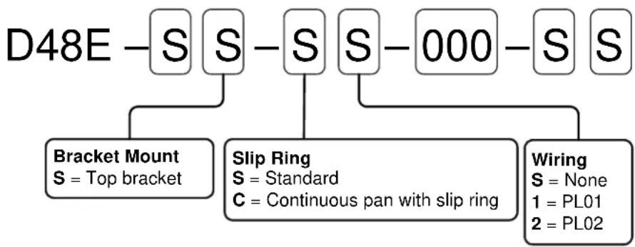
1.5 - Models
Each PTU-D48 E series unit includes a model number that is located on the base of the unit. This number lists the options present on that particular unit. Different options may require specialized instructions, and this manual will refer to this section where necessary to ensure that you are following the appropriate directions.
The PTU-D48 E series model number appears as follows:
flowchart
graph TD
    A["D48E"] --> B["S"]
    A --> C["S"]
    A --> D["S"]
    A --> E["S"]
    A --> F["000"]
    A --> G["S"]
    B --> H["Bracket Mount\nS = Top bracket"]
    C --> I["Slip Ring\nS = Standard\nC = Continuous pan with slip ring"]
    E --> J["Wiring\nS = None\n1 = PL01\n2 = PL02"]

ISM: ISM-equipped PTUs have additional model number options. Please refer to the PTU-D48 ISM Configuration Guide for additional information.
1.6 - PTU-D48 Package Contents
Your PTU-D48 E Series package includes the following items:
• PTU-D48 E Series unit
- Payload mating connector kit (with various payload pass-through configurations)
- Payload mounting brackets – Optional
- Pan-Tilt break-out cable (PTU-CAB-E-25BO) – Optional
- AC/DC power supply (PTU-AC-APS-30V) – Optional
- RS-232 to RS-485 converter (PTU-CONV-RS485C) – Optional
PTU-D48 E Series User's Manual (this document)
• Pan-Tilt E Series Command Reference Manual
- CD containing the PTU Finder utility and other documentation.
1.7 - Related Documentation
The following additional documentation is available for your PTU-D48 E Series unit:
• PTU-D48 E Series Configuration Guide: options and accessories ordering guide
• PTU-D48 E Series Product Datasheet: product specifications
• Pan-Tilt E Series Command Reference Manual: command instructions
1.8 - Additional Resources
FLIR Motion Control Systems, Inc. also maintains a technical support Web site with additional resources for customers in the Support section at www.FLIR.com/MCS. Resources include electronic copies of user manuals, firmware downloads, 3D CAD models, technical notes, and other information.
1.9 - Technical Support
FLIR Motion Control Systems, Inc. provides a range of technical support options:
• Email: MCS-support@FLIR.com
• Web: www.FLIR.com/MCS
• Phone: (650)692-3900, then select "Technical Support"
The preferred method of contacting Technical Support is via email, which helps ensure proper dispatching and tracking to address your questions promptly.
When contacting Technical Support, please provide the following information:
• PTU model and configuration
- Payload (Please include photos, if possible.)
• Parameter settings
• Description of issue/symptoms
This page intentionally left blank.
2 - Safety
This chapter contains important safety instructions. You must read, understand, and comply with all of these safety instructions in order to protect both persons and property. The benefits of a safe installation include increased usability, reliability, and reduced damage to the PTU, payload, and/or other property.
2.1 - Safety Warnings and Cautions
- PTU-D48 installation and setup should be only be performed by qualified personnel.
- The installation must comply with all applicable codes (such as building codes, marine safety codes, etc.).
- The installation must be free of obstructions throughout the entire range of pan-tilt motion. When planning the installation, make sure to take the payload into account to ensure that the PTU-D48 and payload remain unobstructed at all times.
- All mounting methods and materials must be capable of supporting at least four times the combined weight of the PTU-D48, mounted payloads, and cabling.
- Corrosion-resistant hardware (such as stainless steel screws) must be used for all outdoor installations.
- Do not install the PTU-D48 in any location that exceeds the PTU-D48's environmental specifications.
- Always incorporate a readily accessible power disconnect into the installation wiring. (See Sections 3.4 and 3.5.)
- Removing power by disconnecting the power cable or cable harness is not recommended and can result in damage to the system.
- All service procedures must be performed by qualified service personnel in accordance with all applicable instructions.
- If the PTU-D48 is damaged, immediately remove power and contact FLIR Motion Control Systems, Inc.
- Only use replacement parts recommended by FLIR Motion Control Systems, Inc.
- Use caution when lifting the PTU-D48 and/or payload.
- Keep all persons and objects well away from the PTU-D48's panning and tilting radius with payload installed.
- Do not touch or otherwise handle the PTU-D48 while in motion or if there is a possibility of motion. Always remove power before servicing the PTU-D48 and/or payload.
This page intentionally left blank.
3 - Quick Start
The PTU-D48 provides direct Ethernet and serial control for all motions. You may also use a joystick or proprietary controller.
This chapter helps you power up your PTU-D48 and test direct communications from a host computer.
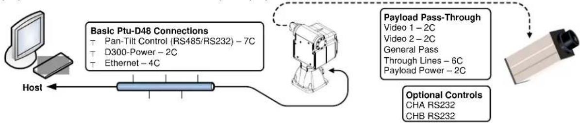
3.1 - System Overview
The PTU-D48 includes an integrated controller that can be accessed using a Web/Ethernet interface. The controller will also accept control commands from any host computer over a serial (RS-232 or RS-485) connection. The basic connections are:
- DC power
• Pan-tilt control via either Ethernet or RS232/485 serial connection
The PTU-D48 also allows payload pass-through wiring that internally routes payload signals (payload power, video, etc.) from a single stationary connector in the PTU-D48 base to a single payload connector that moves with your payload.
flowchart
graph LR
    A["Host"] --> B["Basic Ptu-D48 Connections"]
    B --> C["Payload Pass-Through"]
    C --> D["Optional Controls"]
    style A fill:#f9f,stroke:#333
    style B fill:#ccf,stroke:#333
    style C fill:#cfc,stroke:#333
    style D fill:#fcc,stroke:#333
Figure 1: Pan-Tilt System Overview
You may control the PTU-D48 from any host computer using either the built-in Web interface or the ASCII protocol described in the included Pan-Tilt Command Reference Manual. The PTU-D48 also supports a binary protocol via a C Programmers Interface (PTU-CPI) for high speed, hard real-time controls such as tracking. Drivers are also available using third-party software packages such as LabVIEW and digital video control systems.

ISM: ISM-equipped PTUs use the same connections described in this chapter.
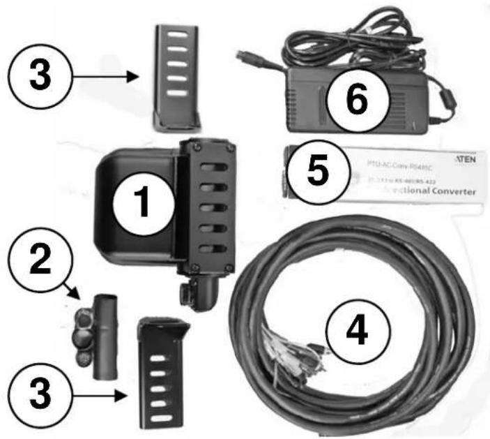
3.2 - Installation Components
A complete PTU-D48 system configuration requires the following components:
- PTU-D48 unit (1)
- Payload mating connector kit – for pass-through models only – (2)
- PTU-D48 User's Manual (this document; not shown)
• Pan-Tilt Command Reference Manual (not shown) - Payload mounting brackets (D48AC-BKT-LSTD) – Optional – (3)
- Breakout cable (PTU-CAB-E-25BO) - Optional - (4)
- RS-232 to RS-485 converter (PTU-CONV-RS485C) – Optional – (5)
- AC/DC power supply (PTU-AC-APS-30V) – Optional – (6)
3.3 - Basic Setup
To perform a basic PTU-D48 setup and installation:
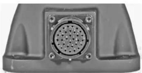
- Mount the PTU-D48 securely to a lab bench, tripod, or other stable platform. Verify that there is enough clearance around the unit. See Section 4.1 for detailed mounting instructions.
- Attach either the optional breakout cable or customer-supplied cable to the 32-pin connector at the base of the PTU-D48 by inserting the connector as keyed and then twisting to secure the connection.
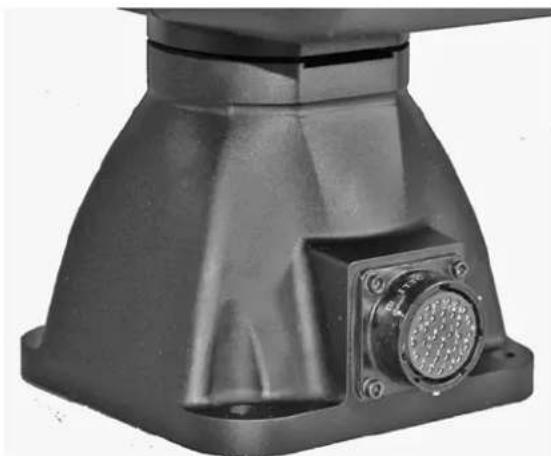
natural_image
Close-up of a black industrial component with a circular connector and mounting holes (no visible text or symbols)
CAUTION: DISCONNECTING THE CABLE WHILE THE PTU-D48 IS POWERED ON CAN DAMAGE THE UNIT. ALWAYS POWER DOWN THE PTU-D48 BEFORE DISCONNECTING THE CABLE.
-
Establish Ethernet or serial wiring to the PTU-D48 as appropriate for your needs.
-
Please see Section 3.4 for Ethernet/Web instructions.
-
Please see Section 3.5 for serial/ASCII instructions.
-
Power on and test the PTU-D48.
3.4 - Ethernet Connection
The PTU-D48 contains a Web-based interface that allows you to test and program various functions. This interface is accessible via the Ethernet connection on the breakout cable.

Note: You may use simultaneous Ethernet and serial connections.
To connect, power on, and test the PTU-D48 using the Ethernet connection and Web interface:
- Connect the RJ-45 Ethernet jack on the breakout cable to the host computer either directly or through a router/hub.
- Connect a power source to the PTU-D48, making sure to incorporate a readily accessible power disconnect (such as a power strip) to allow safe power removal from the system.

CAUTION: REMOVING POWER BY PULLING THE PLUG CAN DAMAGE THE PTU-D48.
- Ensure that the PTU-D48 is clear to move in both axes (pan and tilt) without hitting any obstructions before applying power.

WARNING: HITTING AN OBSTACLE WHILE THE PTU-D48 IS IN MOTION COULD CAUSE A MOUNTING OR OTHER STRUCTURAL FAILURE THAT COULD RESULT IN INJURY OR DEATH.
- Power on the PTU-D48. By default, the PTU-D48 will begin a calibration sequence that will cause it to move from its current position to the center (0) positions in both axes.
- Launch a Web browser. The PTU-D48 supports modern versions of the Microsoft Internet Explorer ^® , Mozilla ^® Firefox ^® , and Google ^® Chrome ^® browsers with JavaScript enabled.
- Run the PTU Finder utility from the CD included with your PTU-D48 package. A list of the individual PTU-D48 units currently connected to the network and their corresponding IP addresses will appear in the application window.

Note: If you have simultaneous Ethernet and serial connections to a PTU-D48 unit, you may enter NI in the terminal to retrieve the IP address of the PTU-D48 unit.
- In your Web browser, navigate to the appropriate IP address (such as http://192.168.1.101). A Web page appears when you are connected to the selected PTU-D48 unit. The PTU-D48 Web interface allows you to configure the network interface, configure various parameters, and control the PTU-D48.
- Navigate to the PTU Control page.
- Click the arrows to pan and tilt the PTU-D48 and verify that it is working properly.
Please refer to Section 6 for instructions on using the Web interface.

ISM: The ISM Web interface includes additional command and configuration options to support the stabilization function. Please refer to the ISM User Manual for instructions on using the ISM Web interface.
3.5 - Serial Connection

Note: You may use simultaneous Ethernet and serial connections.
To connect, power on, and test the PTU-D48 using the serial interface:
- Check which wiring option your PTU-D48 is configured with.
■ If it is PL01, the PTU-D48 provides direct RS-232 support. Skip to Step 3.
- If it is PL02, you may have to connect to the PTU-D48 through an RS-485 converter. Proceed to Step 2.
- Connect the PTU-D48 as follows:
■ Attach the DB25 to DB9 converter on one side of the RS-232 to RS-485 converter.
- Attach one end of the four-pin RJ-11 phone cable to the other side of the RS-232 to RS-485 adapter.
■ Set the switches on the RS-232 to RS-485 converter to T RxON and DCE.
- Attach the four-pin RJ-11 female-to-female adapter to the other end of the phone cable. This is important because the adapter rearranges the pins; the PTU-D48 will not function if the adapter is not attached correctly.
■ Connect the RS485 connector from the breakout cable into the adapter.
■ Provide power to the converter through the included power supply.
-
Attach a standard RS-232 cable between a host PC and the DB9F connector on the PTU-D48 labeled RS-232.
-
Open a terminal program such as HyperTerminal® or TeraTerm®.

Note: HyperTerminal is available with Microsoft® Windows XP® and previous versions. You may download TeraTerm from http://ttssh2.sourceforge.jp/.
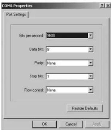
- Create a new connection with the following communications parameters:
■ 9600 baud
■ 8 data bits
■ 1 stop bit
■ no parity
■ no handshaking
- Provide DC power to the PTU-D48. The factory cable (part number PTU-CAB-E-25BO) allows easy plug-in power from the factory AC/DC power supply model PTU-AC-APS-30V. Alternatively, you may provide your own DC power source if appropriate, as described in Section 4.3.

CAUTION: USE AN APPROPRIATELY RATED POWER STRIP WITH SURGE PROTECTION TO ALLOW SAFE POWER REMOVAL WHEN YOU ARE READY TO POWER DOWN.
- Power on the PTU-D48 by turning on the switch on the power strip. If power is working, the unit will begin a self-calibration and text will appear on your terminal identifying the unit's configuration.
- Test pan-tilt operation by typing commands into your terminal program. The following command sequence will familiarize you with basic PTU-D48 operation:
pp2500 * tp-900 * PS1900 * pp0 *
This sequence:
■ sets the pan axis to position 2500
■ sets the tilt axis to position -900
■ sets the pan speed to 1900 positions per second, and
■ sets the pan position back home.
-
Power down the PTU-D48 by turning off the switch on the power strip.
-
Mount and wire your payload (e.g. camera) on the PTU-D48, as described in Sections 4.8 and 4.9.
Please see Appendix C.2.2 for an overview of the ASCII command syntax and a list of commonly used commands. The Pan-Tilt E Series Command Reference Manual contains complete command interface instructions.

ISM: The ISM serial interface includes additional commands to support the stabilization function. Some standard serial commands may also function differently when the PTU is in stabilized mode. Please refer to the E Series Command Reference Manual and the ISM User Manual for instructions on using serial commands with ISM-equipped PTUs.
4 - Installation and Setup
This section describes proper mechanical and electrical PTU-D48 installation.
4.1 - Mounting the Unit
The basic mounting pattern uses four #1/4-20 socket-head cap screws in a 3.375" (85.725mm) square pattern. All four mounting screws must be used, and mount must be strong enough to support the combined load of the PTU-D48 unit, payload, and additional forces exerted on the system (such as wind, G forces, etc.). A good rule of thumb is that the mount must be capable of supporting at least four times the combined weight of the PTU-D48 and payload. For example, a mount for a PTU-D48 with a 15 lb. payload must be able to support at least 104 lbs.

WARNING: FAILURE TO USE ALL FOUR MOUNTING SCREWS AND/OR TO SECURE THE PTU-D48 AND ITS PAYLOAD TO A SUFFICIENTLY STRONG MOUNTING CAN CAUSE THE INSTALLATION TO FAIL. THIS CAN RESULT IN PERSONAL INJURY OR DEATH, AND/OR DAMAGE TO THE PTU-D48 UNIT AND/OR PAYLOAD.
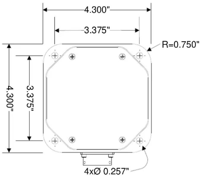
Figure 2: Hole Mounting Pattern
4.2 - Wiring and Connectors
The standard PTU-D48 has a base connector and may also have an optional payload connector for customer attachment. Different PTU-D48 wiring options may require different connectors. Please verify your wiring configuration and then refer to Appendix A for detailed pin-out and connector requirements.
4.2.1 - Mechanical Overview
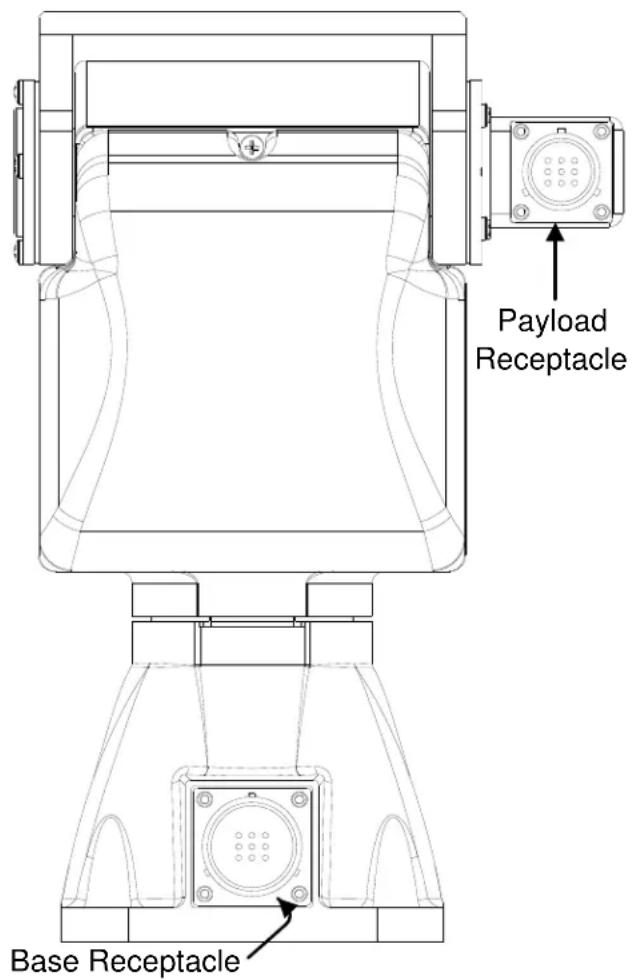
The PTU-D48 contains one or two receptacles.
- Base Receptacle: The base of the PTU-D48 houses the 32-pin base receptacle that complies with MIL standard MIL-C-26482.
- Payload Receptacle (Optional): If equipped, the payload connector is a 19-pin circular receptacle that complies with MIL standard MIL-C-26402. The appropriate male connector complies with MS3126F14-19P. Each PTU-D48 with pass-through option includes one male connector. You may order additional connectors from FLIR Motion Control Systems, Inc.
Basic control requires connecting a DC power source and a host PC to the PTU-D48. The supplied breakout cable and power supply allow you to have your PTU-D48 plugged in and running within minutes. Appendix A contains specific pin outs and wiring diagrams for the available PTU-D48 wiring configurations; if needed, you may use this information to make custom cables to suit your specific installation requirements. Please refer to Section 3 for basic connection and power-on instructions.
The PTU-D48 also provides payload pass-through signals that connect between pins in the base receptacle to corresponding pins in the payload receptacle. Additional pins in the payload receptacle provide other payload controls to the PTU-D48 controller board, including auxiliary RS-232 ports.

CAUTION: ALWAYS FOLLOW ALL APPLICABLE SPECIFICATIONS (INCLUDING BUT NOT LIMITED TO MAXIMUM VOLTAGE AND CURRENT) WHEN ATTACHING PAYLOAD SIGNALS TO THE SYSTEM.
4.2.2 - Wiring Options
The PTU-D48 is offered with the following wiring options:
- PL01: This option provides an alternate RS-232 communication option for communicating with the PTU-D48 in addition to the RS-485 lines, and includes a total of 10 payload pass-through lines that provide:
■ 2 video channels (4C)
■ 1 power circuit (3C)
■ 3 general I/O lines (3C).
The PTU-D48 also provides two auxiliary serial ports to the payload connector that can be controlled using special commands for use controlling cameras or other peripherals without an additional serial port. Please refer to Appendix A.3 for more information about the PL01 wiring option.
- PL02: The standard wiring option provides the maximum available pass-through lines from the PTU-D48 to the payload, including:
■ 2 video channels (4C)
■ 1 set of power lines (3C)
■ 6 general I/O lines (6C)
The PTU-D48 also provides RS-232 control to the payload, which allows the PTU-D48 to be controlled by a module on the payload side. Please refer to Appendix A.4 for more information about the PL02 wiring option.
With either option, the standard slip ring and connectors offer 32 termination pins at the base and 19 pins at the payload (including through a slip ring, if equipped). The PTU-D48 requires a minimum of seven connections at the base for power, RS-485 communications, and shielding.
4.3 - Power Sources
The PTU-D48 requires an unregulated 12-30VDC power source capable of 48 continuous peak watts.
- For maximum PTU-D48 performance, use the highest motor voltage within the allowable range.
- For the quietest and smoothest PTU-D48 operation, you can use a lower motor voltage, such as 24VDC.
The PTU-D48 pan-tilt maximum speed depends on the input voltage. 30 VDC provides the highest maximum speed; lower voltages will reduce the maximum achievable speed.

CAUTION: THE PTU-D48 CONTAINS OVER-VOLTAGE AND OVERCURRENT PROTECTION; HOWEVER, SUSTAINED OVERLOAD CAN DAMAGE THE UNIT.
4.4 - Fusing
If you are using a DC power source that is capable of supplying current beyond the PTU-D48 rated maximums, you must add an appropriate fuse in series with the DC power source. For example, you must fuse a connection made to a vehicle battery or lighter plug.

WARNING: FAILURE TO PROPERLY FUSE THE PTU-D48 POWER SOURCE COULD OVERLOAD INTERNAL PROTECTION DEVICES AND CAUSE DEATH, PERSONAL INJURY, AND/OR DAMAGE TO THE UNIT.
4.5 - Shielding
Shielding protects the PTU-D48 from external Electromagnetic Interference (EMI) and prevents radiation emission from internal and external cabling. Proper shielding must be used to meet the regulatory requirements described in Appendix E. All PTU-D48 wiring configurations provide a shield pin at both the base and the payload, as described in Appendix A. This shield is also attached to the PTU-D48 housing. The shield pin is not connected to ground internally. The shield potential will vary from ground and must not be confused with a ground pin.
Ideally, either the PTU-D48 chassis or the shield pin at the base connector should be routed to a long grounding rod that is embedded in the ground. If needed, it is also acceptable to route the shield pin to the power ground through a surge protection device.

CAUTION: THE PTU-D48 WILL NOT BE PROPERLY SHIELDED UNTIL THE SHIELD PIN IS PROPERLY CONNECTED.
4.6 - Interface and Host Settings
The PTU-D48 includes both an Ethernet connection and either RS-232 or RS-485 communications. You may connect to your PTU-D48 using either or both of these methods; the Web interface is only available when using an Ethernet connection, and the terminal interface is only available when using a serial connection.
4.6.1 - Ethernet Connection
The PTU-D48 Ethernet connection uses a standard Cat-5 (RJ-45) network cable.
- You may connect the PTU-D48 directly to a host computer or indirectly through a router, hub, etc.
- The PTU-D48 will either accept IP addresses from a DHCP server or select its own IP address if connected directly to the host computer.
- You do not need a crossover cable.
- If needed, you may use a coupling to extend the Ethernet connection on the breakout cable.

Note: The Ethernet and serial interfaces may be connected simultaneously; however, you should only use one interface at a time for command and control of the PTU-D48.
Connect, power on, and test the PTU-D48 using the Ethernet connection and Web interface as described in Section 3.4.
4.6.2 - RS-232 Electrical Connection
PTU-D48 units with RS-232 communications have the following connections:
• TxD: Pin 2 (carries data from the PTU-D48)
• RxD: Pin 3 (carries data to the PTU-D48)
GND: Pin 5

Note: TxD and RxD assignments can vary depending on your host computer. If your initial connection does not work, try using a null modem.
Serial communication between the PTU-D48 and your host computer should be set as follows:
- Baud rate: 9600. You may adjust the baud rate using software commands. Please refer to the Pan-Tilt E Series Command Reference Manual for instructions.
- Start bit: 1
- Data bits: 8
- Stop bit: 1
- Handshaking: off
• XON/XOFF: not used
4.6.3 - RS-485 Electrical Connection
PTU-D48 units with RS-485 communications have the following connections:
- Duplex: full
- Connections: Tx+, Tx-, Rx+, and Rx-
• Voltage: RS-422 or RS-485 levels
Serial communication between the PTU-D48 and your host computer should be set as follows:
- Baud rate: 9600. You may adjust the baud rate using software commands. Please refer to the Pan-Tilt E Series Command Reference Manual for instructions.
- Start bit: 1
-
Data bits: 8
-
Stop bit: 1
- Handshaking: off
• XON/XOFF: not used
4.7 - Initial Power-Up and Test
This section describes how to power up and test your PTU-D48 using either the Web or serial interface. Test and verify all cable connections and connector wiring before power-up.

Note: Complete the initial installation and testing, then exercise the PTU-D48 and familiarize yourself with its operations and commands before mounting your payload (such as a camera).
4.7.1 - Web Interface
To test the PTU-D48 using the Web interface, follow the procedure in Section 3.4 to connect the PTU-D48, power on the unit, and access the Web interface.
The Web interface has the following pages:
- PTU Config: Allows you to configure speed, acceleration, and power options.
- Network: Allows you to configure the PTU-D48 unit's IP and MAC addresses.
• PTU Control: Allows you to control the PTU-D48.
Please see Section 6 for more information about the Web interface. Use the PTU Control page (see Section 6.3) to test PTU-D48 motion and exercise the unit.
4.7.2 - Terminal Interface
To test the PTU-D48 using the serial interface:
- Configure the RS-232 or RS-485 port on the host computer as described in Section 3.5.
- Power up the PTU-D48. A boot message will appear on your terminal screen and the unit will begin a reset cycle. An asterisk (*) appears on your screen when the reset cycle is finished. If the PTU-D48 did not reset properly, please refer to the troubleshooting instructions below.
- Please see Appendix C.2.3 for a list of basic commands, and the Pan-Tilt E Series Command Reference Manual for a complete list of commands and associated parameters and other usage instructions.
4.8 - Payload Mounting
The PTU-D48 payload bracket system can be configured in a number of ways to support a variety of payloads including cameras, lasers, antennas, and other equipment. Figure 3 shows all bracket configurations available for the PTU-D48.

WARNING: FAILURE TO FOLLOW ALL PAYLOAD MOUNTING INSTRUCTIONS COULD RESULT IN A STRUCTURAL FAILURE THAT MAY RESULT IN DEATH, PERSONAL INJURY, AND/OR DAMAGE TO THE UNIT.
The following guidelines apply to all payload mounts:
- The maximum payload mounting screw size is 14 ”.
• Always use washers, lock washers, etc. as appropriate. - If the PTU-D48 is being mounted in an outdoor location, use corrosion-resistant hardware (such as stainless steel).
- Apply thread locking compound to all screws, such as Loctite® 242, which is suitable for applications that are field serviceable since it is easily removable with common hand tools and works with both stainless and plated metals. Consider other compounds for high-shock/vibration applications where field service is not a concern.
The PTU-D48 allows the following bracket mounting options:
natural_image
Three technical line drawings of a mechanical device with mounting base and support brackets (no text or symbols)Figure 3: Bracketing Options
4.8.1 - Side Bracket Attachment
To attach side mounting brackets:
- Verify that the PTU-D48 has been powered on and allowed to reset, which places the mounting hub in its "home" position.
- Power off the PTU-D48.
- Orient the bracket so the horizontal mounting arm is on the bottom.
- Attach the bracket using 4 screws torque to 12 inch-pounds. The thread holes in the hub come with thread locking compound applied to them. Reapply thread lock to the hub whenever you remove the bracket.
- Reset the PTU-D48 and ensure that the bracket moves properly throughout the entire range of motion.

Note: If you ordered your PTU-D48 with a top bracket, the unit will arrive with the bracket already attached.
4.8.2 - Payload Attachment
The following guidelines apply to all payload attachments:
- Mount all payloads as close to the PTU-D48 as possible. This minimizes the distance between the payload Center of Gravity (CG) and the center of rotation of the axes, which reduces stress on the PTU-D48 unit and mounting. It also improves performance by reducing the amount of torque required to move the payload.
- Verify that the payload will clear the PTU-D48 housing and all surrounding objects throughout the entire range of motion.
- The PTU-D48 is rated for a maximum load of 15 lbs; however, load distribution affects the actual weight that the PTU-D48 can safely move. The amount of torque needed to move a payload depends on a number of factors such as payload weight, distance from the payload CG to the center of rotation, acceleration and speed settings, power levels, environmental factors, etc.
- The PTU-D48 allows full control over acceleration, speed, and power levels. Mount your payload and configure these parameters appropriately to ensure reliable operation.
To attach and test your payload:
- Mount your payload. Side mounting is preferable for heavy loads because this keeps the payload CG closer to the tilt axis, thereby minimizing torque requirements.
- Verify that the payload is securely attached to the payload bracket.
- Move the PTU-D48 tilt axis through its entire range to test its ability to carry the load.
Top-mounted payload CG is above the tilt axis center of rotation and requires more torque.

CAUTION: THE CG OF TOP-MOUNTED PAYLOADS IS FURTHER FROM THE TILT AXIS AND MAY REQUIRE MORE TORQUE THAN A SIMILAR SIDE-MOUNTED PAYLOAD.
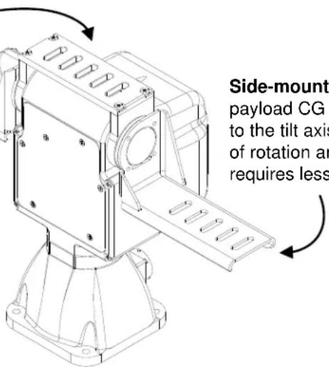
Side-mounted payload CG is closer to the tilt axis center of rotation and requires less torque.
- If you are using the Web interface, open the PTU Control page and click the arrows to move the PTU-D48 through its full range of tilt motion, as described in Section 6.3. If needed, click Halt to stop the PTU-D48 immediately.
- If you are using the terminal interface, enter TN TX to query the tilt minimum and maximum limits, then enter TP
A TP to cycle the PTU-D48 through its entire tilt range (where is the number returned by the TN query and is the number returned by the TX query). If needed, enter H to stop the PTU-D48 immediately.

WARNING: STOP THE PTU-D48 IMMEDIATELY BY EITHER CLICKING HALT (WEB INTERFACE) OR ISSUING AN H COMMAND (SERIAL INTERFACE) IF THE PAYLOAD IS ABOUT TO COLLIDE WITH THE PTU-D48 AND/OR ANOTHER OBSTACLE. A COLLISION COULD CAUSE A STRUCTURAL FAILURE THAT MAY RESULT IN INJURY OR DEATH.

ISM: Verify that the payload will clear all obstacles when the PTU is in both normal and stabilized modes.
If the load is too heavy or moving too quickly, the PTU-D48 will lose synchronization, which will be audible as a grinding sound from the PTU-D48 motors. Stop the test immediately if this occurs, and refer to Sections 5.3.2 and 5.3.3. This does not damage the PTU-D48 but does indicate that the payload is not mounted and/or the PTU-D48 is not configured correctly to move the payload.

Note: Please refer to Section 5.3.2 for more information on configuring the PTU-D48 for heavier payloads.

CAUTION: DO NOT PROCEED BEYOND THIS STEP UNLESS AND UNTIL THE PTU-D48 PASSES THE TILT AXIS MOTION TEST.
-
Move the PTU-D48 pan axis through its entire range to test its ability to carry the load.
-
If you are using the Web interface, open the PTU Control page and click the arrows to move the PTU-D48 through its full range of pan motion, as described in Section 6.3. If needed, click Halt to stop the PTU-D48 immediately.
- If you are using the terminal interface, enter PN PX to query the pan minimum and maximum limits, then enter PP
A PP to cycle the PTU-D48 through its entire tilt range (where is the number returned by the PN query and is the number returned by the PX query). If needed, enter H to stop the PTU-D48 immediately.

WARNING: STOP THE PTU-D48 IMMEDIATELY BY EITHER CLICKING HALT (WEB INTERFACE) OR ISSUING AN H COMMAND (SERIAL INTERFACE) IF THE PAYLOAD IS ABOUT TO COLLIDE WITH THE PTU-D48 AND/OR ANOTHER OBSTACLE. A COLLISION COULD CAUSE A STRUCTURAL FAILURE THAT MAY RESULT IN INJURY OR DEATH.
If the load is too heavy or moving too quickly, the PTU-D48 will lose synchronization, which will be audible as a grinding sound from the PTU-D48 motors. Stop the test immediately if this occurs, and refer to Sections 5.3.2 and 5.3.3.
- If the PTU-D48 passes the above pan and tilt axis load handling tests, you are ready to begin controlling your payload using the commands described in the Pan-Tilt E Series Command Reference Manual.
4.9 - Payload Wiring Connector (Optional)
The PTU-D48 provides payload pass-through signals that connect between pins in the base receptacle to corresponding pins in the payload receptacle. Additional pins in the payload receptacle provide other payload controls, including auxiliary RS-232 ports and TTL control. The payload connects to the receptacle via a male MS3126F14-19P plug. Appendix A.2 displays this connector and corresponding pin-out.

CAUTION: FOLLOW ALL APPLICABLE SPECIFICATIONS FOR PASS-THROUGH SIGNALS, SUCH AS MAXIMUM VOLTAGE AND CURRENT LEVELS.
5 - Configuring & Programming
This chapter describes how to configure and program your PTU-D48.

Note: You may also have a simultaneous Ethernet connection to the Web interface, as described in Section 3.4.
Follow the appropriate instructions to connect the PTU-D48 to the host computer, power it on, and access it via:
• Web: Section 3.4.
- Serial: Section 3.5.
5.1 - Range of Motion
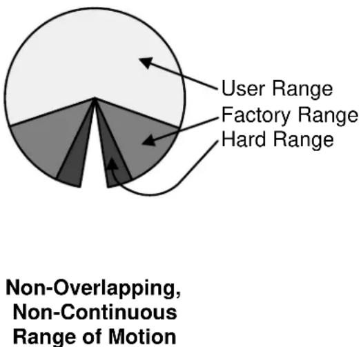
The PTU-D48 range of motion can be limited in the following ways:
- Hard: A hard limit physically cannot be exceeded. For example, PTU-D48 units without a slip ring physically cannot pan across all 360°, and units with
Overlapping Range of Motion
top-mounted payloads may have smaller tilt limits than units with side-mounted payloads. A physical pin on the PTU impedes movement.
- Factory: Factory limits are smaller than hard limits to prevent physical damage to the PTU-D48 and/or payload. These limits may be exceeded in certain circumstances, such as disabling pan limits on a PTU-D48 with a slip ring.
- User: User limits are programmable limits that are smaller than hard limits and can be as large as factory limits.
The PTU-D48 uses high-precision optical limit sensors that allow faster reset sequences and user-programmable ranges. It can also be equipped with optional mechanical stops that will limit pan/tilt motion to preset limits. It is possible to set these stops to allow overlapping limits, as shown in the image on the previous page.

Note: If needed for your application, order optional mechanical stops with your PTU-D48 because they are installed during manufacturing.
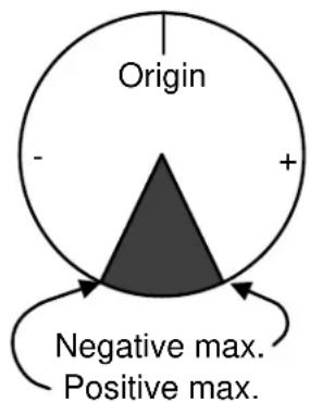
5.1.1 - Default Limits
In the following image:
- The positive pan axis direction is clockwise when looking down at the top of the PTU-D48.
- The positive tilt axis direction is clockwise when looking sideways at the PTU-D48 with the motors and connectors facing to the right.
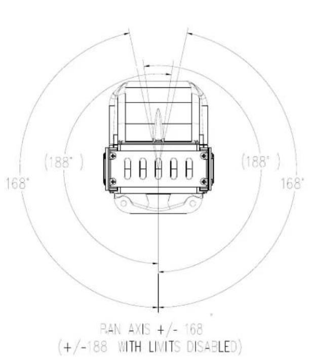
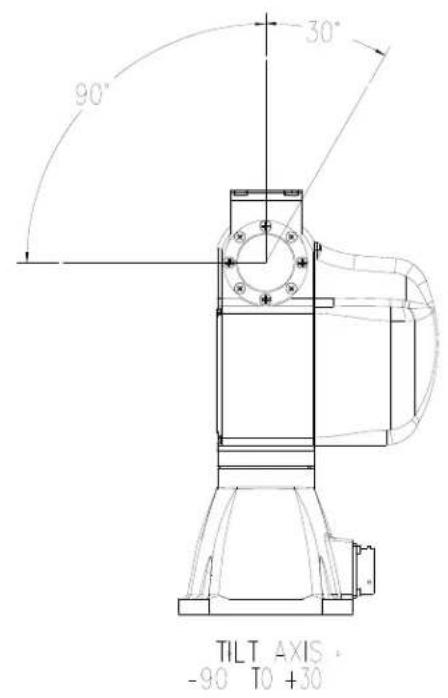
Figure 4: Pan-Tilt Default Factory Limits

Note: The default pan axis user limits are +/- 168°. The default tilt axis limits are +30° and -90°.
5.2 - Resolution and Step Modes
The PTU-D48 uses stepper motors that drive the unit through a gear reduction system. The internal controller allows stepper motor control in manual ( 12 , 14 , and 1/8) or automatic step modes. The following table lists the pan and tilt axis resolution in degrees.
| 12 STEP | 14 STEP | 1/8 STEP | |
| PAN AXIS | 0.026° | 0.013° | 0.006° |
| TILT AXIS | 0.013° | 0.006° | 0.003° |

Note: Larger step modes increase torque and maximum speed vs. smaller step modes. The PTU-D48 includes an automatic stepping mode (auto-step) that optimizes this tradeoff for many applications. You may command the PTU-D48 in 1/8 steps when in automatic stepping mode.
5.3 - User-Programmable Settings
The PTU-D48 has a number of user-programmable parameters that can significantly affect performance for a given payload and application. These parameters should be set to values that are appropriate for your payload and application needs. This section provides an overview of how to optimize your PTU-D48 for high-power and/or high-speed operation. Please refer to the Pan-Tilt E Series Command Reference Manual for complete instructions.

CAUTION: USE HIGH-SPEED AND/OR HIGH-POWER SETTINGS WITH CARE, PARTICULARLY WHEN MOUNTING A HEAVY AND/OR BULKY PAYLOAD.

WARNING: FAILURE TO ADEQUATELY SECURE THE PTU-D48 TO A MOUNTING THAT CAN WITHSTAND THE FORCES APPLIED BY BOTH HIGH-SPEED, HIGH-POWER MOVEMENT AND ENVIRONMENTAL FASCTORS SUCH AS VEHICLE MOVEMENT OR WIND CAN CAUSE A STRUCTURAL FAILURE RESULTING IN INJURY OR DEATH
5.3.1 - High-Speed Operation
The following factors should be considered when planning high speed operation:
- Load weight, weight distribution, and dynamics.
- Move the payload as close to the axis centers of rotation as possible. Doing this will reduce the torque required to move the payload and allow a higher top speed.
- Balancing the load, such as by using a counterweight or splitting the payload into two pieces can also help significantly.
• Desired upper speed limit.
• Rate of acceleration.
• The base (start-up) speed.
- Power supply voltage. Higher voltages within the permissible range significantly improve axis speed and acceleration performance.
- In-motion power modes. If the duty cycle is less than 20%, you may use high move power to increase the top speed.
- Multi-axis dynamics. Simultaneously moving the tilt and pan axes affects the forces exerted on the PTU-D48.
- Always begin high-speed tests on each axis in isolation. Only perform simultaneous pan-tilt movements once each individual axis is optimized.
- The base speed is the PTU-D48 minimum speed. In practice, the unit will instantly accelerate to this speed. Setting a base speed can help speed up movement by eliminating a segment of acceleration time.
- Aggressive acceleration settings with heavy payloads can cause increased wear on the PTU-D48.
5.3.2 - Heavy-Payload Operation
If the PTU-D48 fails the initial load handling tests, you may be able to program it for higher-power operations. The speed and acceleration of a mechanical system depend on the inertial properties of the payload. The ability of the PTU-D48 to successfully move the payload without losing synchronization depends upon the inertial payload factors and their relationship to power supply voltage, unit speed, acceleration, position, motor torque, etc.
To increase payload capacity:
Configure the PTU-D48 for increased motor current and torque. If your move duty cycle is less than 20%, you can set the Move Power to High (Web) or use the following serial commands:
PMH TMH PHR THR.
You may also:
- Move the payload CG closer to the PTU-D48 tilt axis. See Section 4.8.2.
- Use a higher-voltage power source in the permissible range
• Determine if the payload can be modified to lighten it. - Set the base speed to 0.
- If the PTU-D48 is having trouble resetting the tilt axis, try using user limits to reduce the tilt-axis range of motion.
- Reduce speed and/or acceleration.
Please refer to the Pan-Tilt E Series Command Reference Manual for more information.
5.3.3 - Battery Powered Operation
The PTU-D48 can be battery powered. Battery-powered applications must conserve as much power as possible. The PTU-D48 includes commands that control pan-tilt motor power consumption both while moving and when stopped. Please refer to the Pan-Tilt E Series Command Reference Manual for more information.

CAUTION: ALWAYS USE A FUSE WHEN CONNECTING THE PTU-D48 TO A BATTERY.
This page intentionally left blank.
6 - Web Interface
This chapter describes how to configure and program your PTU-D48 using the Web interface.

Note: You may also have a simultaneous serial connection to a terminal, as described in Section 3.4.

ISM: The ISM Web interface includes additional command and configuration options to support the stabilization function. Please refer to the ISM User Manual for instructions on using the ISM Web interface.
Follow the instructions in Section 3.4 to connect the PTU-D48 to the host computer and power it on, obtain the IP address, and launch the Web interface in a browser window. If your PTU-D48 includes the optional ISM module, please refer to the ISM documentation.

Note: Commands issued via the Web interface correspond to commands issued via the serial interface. Please refer to the Pan-Tilt E Series Command Reference Manual for a complete list of serial commands.
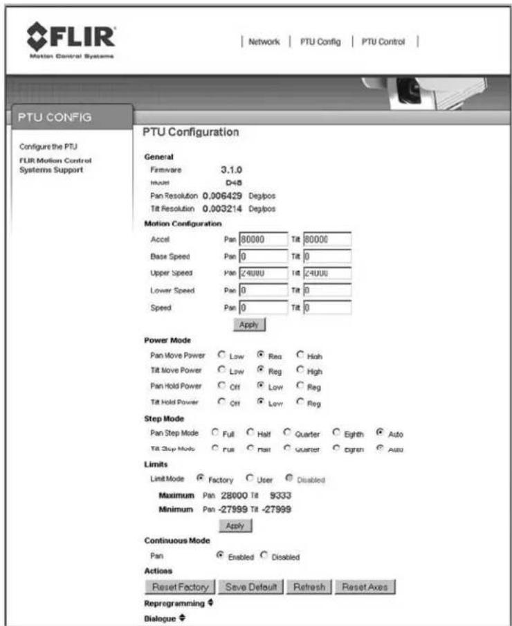
6.1 - PTU Configuration Page
The PTU Config page appears when you click the PTU Config link in the top menu. To use this page:
- Make your desired changes.
- Click the appropriate Apply button to apply certain changes (see below).
- Click the appropriate action button at the bottom of the page.
This page allows you to view and configure the following options for your PTU-D48:
- General: The General section of the PTU Config page displays the following information:
■ Firmware: The PTU-D48 installed firmware revision.
■ Model: The PTU-D48 model number.
- Pan Resolution: Horizontal motion resolution, in degrees. This number varies depending on your selected step mode (see below). Each unit of resolution equals one “position.”
- Tilt Resolution: Vertical motion resolution, in degrees. This number varies depending on your selected step mode (see below). Each unit of resolution equals one “position.”
- Motion Configuration: The Motion Configuration section of the PTU Config page allows you to specify the following motion options for both pan and tilt in positions. One position equals one unit of resolution:
■ Speed: Pan and tilt speed, in positions per second.
■ Acceleration: Pan and tilt acceleration and deceleration in positions per second per second. The PTU-D48 will accelerate at this rate to the selected speed, maintain this speed as long as necessary, and then slow back down at the same rate.
■ Base Speed: Speed the PTU-D48 instantly accelerates to.
■ Upper Speed: Maximum PTU-D48 speed that can be commanded.
■ Lower Speed: Minimum PTU-D48 speed that can be commanded.
Click Apply to make your desired speed/acceleration changes on the PTU-D48.
- Power Mode: The Power Mode section of the PTU Config page allows you to specify the following power options for each axis:
■ Move Power: Amount of power the PTU-D48 uses when moving the payload.
- Hold Power: Amount of power the PTU-D48 uses in order to hold the payload in a fixed position.
The following power settings are available for pan and/or tilt power:
- Off: Setting the hold power to Off means that the PTU-D48 motor(s) are completely off when the payload is not moving in the selected axis or axes.
- Low: Setting the hold and/or move power to Low means that the PTU-D48 motors draw lower power while moving and/or holding.
■ Reg: Setting the hold and/or move power to Reg means that the PTU-D48 motors draw normal power while moving and/or holding.
- High: Setting the move power to High means that the PTU-D48 motors draw maximum power while moving the payload in the pan and/or tilt axis. This power setting should be used for intermittent (<20%) duty cycles.

CAUTION: THE HIGH POWER SETTING IS INTENDED ONLY FOR INTERMITTENT DUTY CYCLES (<20%). EXTENDED HIGH POWER CYCLES CAN OVERHEAT THE PTU-D48 MOTORS.
- Step Mode: The Step Mode section of the PTU Config page allows you to specify the following resolution options for each axis:
■ Full: Low resolution.
- Half: Medium resolution.
■ Quarter: High resolution.
- Eighth: Maximum resolution. This setting provides the greatest aiming accuracy.
- Auto: Internally switches between step modes for optimal movements, but all commands and accuracy are in 1/8 step mode.
Changing the step mode requires a calibration reset. Please see Section 5.2 for more information about steps and fractional steps.
- Limits: The Limits section of the PTU Config page allows you to specify the pan and tilt range of motion for your PTU-D48. Please see Section 5.1 for an explanation of limit types and a visual depiction of the PTU-D48 range of motion.
- Factory: Checking the Factory radio button sets the PTU-D48 range of motion to its factory default. The range of motion appears below.
- User: Checking the User radio button allows you to program your own range of motion. The Minimum and Maximum fields become editable, allowing you to enter your desired range for both pan and tilt.
Click the Apply button after setting your desired range of motion to program the PTU-D48.
- Continuous Mode: Enabling continuous pan mode by checking the Enable radio button overrides the factory or user pan limits, allowing the PTU-D48 to pan a full 360° if it has the optional pan-axis slip ring installed. Checking the Disable radio button limits the PTU-D48 pan range of motion to the factory or user limits you specified above. This requires a calibration reset.
- Action Buttons: The action buttons at the bottom of the PTU Config page allow you to perform the following actions:
- Reset Factory: Clicking the Reset Factory button restores factory default speed, acceleration, power, and limit settings to the PTU-D48. This erases any user limits.
- Save Default: Clicking the Save Default button saves the changes you made on the PTU Config page as the default settings for the PTU-D48.
- Refresh: Clicking the Refresh button updates the PTU Config page with the values stored on the PTU-D48.
- Reset Axes: Clicking the Reset Axes button cycles the PTU-D48 through a complete calibration reset cycle.
- Reprogramming: The Reprogramming section of the PTU Config page allows you to upload firmware to the PTUD48.

CAUTION: REPROGRAMMING NEW FIRMWARE IN THE PTU-D48 CAN DAMAGE THE UNIT IF NOT DONE PROPERLY. ONLY REPROGRAM YOUR UNIT UNDER THE DIRECT GUIDANCE OF FLIR TECHNICAL SUPPORT.
- Dialogue: The Dialogue section of the PTU Config page displays information that can be useful when debugging the PTU-D48.
6.2 - Network Page
The Network page appears when you click the Network link in the top menu.
This page allows you to configure the following options for your PTU-D48:
- Host Name: Name of the PTU-D48 unit. If you have multiple PTU-D48 units on the network, you may enter a unique name for the currently selected PTU-D48 unit to make reconnection faster.
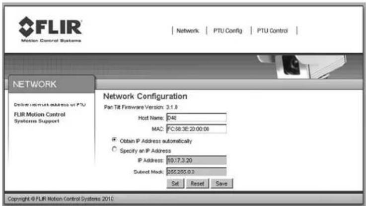
- MAC: Displays the unique Media Access Control (MAC) address for the PTU-D48 unit. You may change this address if necessary.
- Automatic IP Address: Checking the Obtain IP address Automatically radio button allows the PTU-D48 to either accept IP information from a DHCP server (such as a router) or select its own IP information (if connected directly to a host computer).
- Manual IP Address: Checking the Manual IP Address radio button lets you specify the following information:
■ IP Address: IP address for the PTU-D48 unit.
- Subnet Mask: Subnet mask of the network the PTU-D48 is connected to.
After changing network information, click the appropriate action button at the bottom of the page:
- Set: Clicking Set implements your changes but does not save them to the PTU-D48.
- Reset: Clicking Reset reverts the PTU-D48 to factory default settings.
- Save: Clicking Save implements your changes and saves them to the PTU-D48.
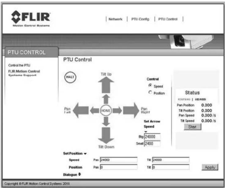
6.3 - PTU Control Page
The PTU Control page appears when you click the PTU Control link in the top menu.
This page allows you to control your PTU-D48 as follows:
• Home: Clicking Home returns the PTU-D48 to its home pan and tilt positions.
- Directional controls: The directional controls allow you to move the PTU-D48 left and right (pan), and up and down (tilt).
■ Halt: Clicking Halt immediately stops the PTU-D48 in its current position.
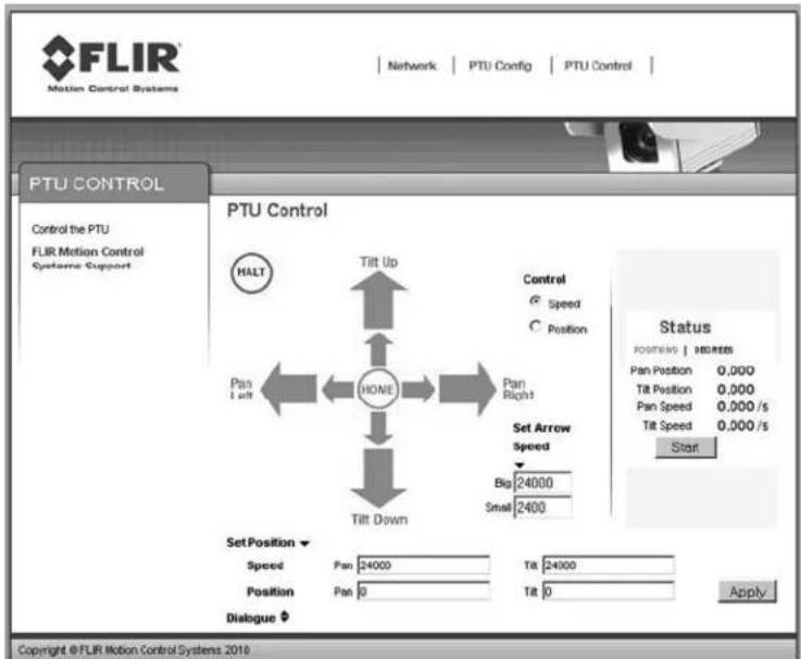
- Small Arrow: Clicking a small arrow moves the PTU-D48 by either the smaller position step size or at the lower speed (see below).
-
Big Arrow: Clicking a big arrow moves the PTU-D48 by either the larger position step size or at the higher speed (see below).
-
Speed/Position selection: Check the appropriate radio button to control the PTU-D48 by Position (the unit will move by the selected amount when an arrow is clicked) or Speed (the unit will accelerate up to the selected speed when an arrow is clicked, and will continue moving at that speed until the arrow is released).
-
Set Arrow Step Size: The Set Arrow Step Size fields allow you to specify either how many positions the PTU-D48 will move each time an arrow is clicked (if you selected Position), or how fast it will move (if you selected Speed).
-
Big: The Big number specifies either the number of positions the PTU-D48 will move each time you click a big arrow (if you selected Position) or the number of positions per second the PTU-D48 will move (if you selected Speed).
- Small: The Small number specifies either the number of positions the PTU-D48 will move each time you click a small arrow (if you selected Position) or the number of positions per second the PTU-D48 will move (if you selected Speed).
- Status: The Status section of the PTU Control page displays the PTU-D48 position and speed in real time. Click the appropriate link to see this information in Degrees or Positions.
■ Position: Pan and tilt location of the PTU-D48 in degrees or positions.
■ Speed: Pan and tilt speed of the PTU-D48 in degrees or positions per second.
- Start/Stop: Clicking the Start/Stop button toggles updating the PTU-D48 status on and off.
- Set Position: The Set Position section of the PTU Control page allows you to manually enter position and/or speed information. Please see Section 5.1 for an explanation of limit types and for a visual depiction of the PTU-D48 range of motion.
■ Speed: Enter your desired pan and/or tilt speeds in the Speed fields.
■ Position: Enter your desired pan and/or tilt position in the Position fields.
Click the Apply button to move the PTU-D48 to the specified position at the specified speed.
A. - Electrical Specifications
This Appendix describes the PL01 and PL02 wiring options for the PTU-D48. Please refer to the appropriate section for your unit, and to Section 4.2.1 for a mechanical overview.

CAUTION: DO NOT EXCEED MAXIMUM RATED PASS-THROUGH AMPERAGES. FUSE PAYLOADS AT RATED TRIP VALUES. THE PTU-D48 WARRANTY DOES NOT COVER DAMAGE CAUSED BY OVERCURRENT SITUATIONS.

CAUTION: ALWAYS TERMINATE THE SHIELD LINE TO AN APPROPRIATE SYSTEM SHIELD OR GROUND CONNECTION.
In general:
• TX lines carry data from the PTU-D48.
• RX lines carry data to the PTU-D48.

ISM: ISM-equipped PTUs are equipped with the PLO2 wiring option.
A.1 - 32-Pin Base Connector
This table displays the PTU-D48 32-pin base connector pin assignments for both the PL01 and PL02 wiring options. MIL-C-26482.
| PIN | PL01 | PL02 |
| A | RESERVED | RESERVED |
| B | HOST RS232_RX | RESERVED |
| C | HOST RS232_TX | RESERVED |
| D | D48- | D48- |
| E | D48+ | D48+ |
| F | SHIELD | SHIELD |
| G | HOST RS485_RX+ | HOST RS485_RX+ |
| H | HOST RS485_RX- | HOST RS485_RX- |
| J | ETHERNET_TX- | ETHERNET_TX- |
| K | ETHERNET_RX+ | ETHERNET_RX+ |
| L | ETHERNET_RX- | ETHERNET_RX- |
| M | PT1 | PT1 |
| N | VIDEO1_GROUND | VIDEO1_GROUND |
| P | VIDEO1_SIGNAL | VIDEO1_SIGNAL |
| R | VIDEO2_GROUND | VIDEO2_GROUND |
| S | VIDEO2_SIGNAL | VIDEO2_SIGNAL |
| T | RESERVED | PT4 |
| U | RESERVED | RESERVED |
| V | HOST RS232_GND | RESERVED |
| W | PAYLOAD - | PAYLOAD - |
| X | PAYLOAD + | PAYLOAD + |
| Y | HOST RS485_TX+ | HOST RS485_TX+ |
| Z | HOST RS485_TX- | HOST RS485_TX- |
| a | ETHERNET_TX+ | ETHERNET_TX+ |
| b | PT2 | PT2 |
| c | PT3 | PT3 |
| d | RESERVED | PT5 |
| e | RESERVED | PT6 |
| f | RESERVED | RESERVED |
| g | RESERVED | RESERVED |
| h | RESERVED | RESERVED |
| j | RESERVED | RESERVED |
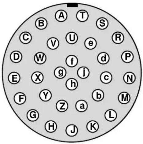
natural_image
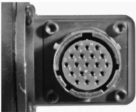
Close-up of a black plastic electronic device with a circular connector and mounting holes (no visible text or symbols)A.2 - 19-Pin Payload Connector
This table displays the PTU-D48 19-pin payload connector pin assignments for both the PL01 and PL02 wiring options. MIL-C-26402.
| PIN | PL01 | PL02 |
| A | CHA_RX | HOST_RS232_TX |
| B | CHA_TX | HOST_RS232_RX |
| C | CHB_RX | TTL_OP2 |
| D | CHB_TX | TTL_OP3 |
| E | CHB_DTR | TTL_OP4 |
| F | SHIELD | SHIELD |
| G | VIDEO1_GROUND | VIDEO1_GROUND |
| H | VIDEO1_SIGNAL | VIDEO1_SIGNAL |
| J | TTL_OP2 | PT4 |
| K | CHA_TTL_RX | PT5 |
| L | CHA_TTL_TX | PT6 |
| M | RS232_GND | HOST_RS232_GND |
| N | PT3 | PT3 |
| P | PT2 | PT2 |
| R | PAYLOAD - | PAYLOAD - |
| S | PAYLOAD + | PAYLOAD + |
| T | VIDEO2_SIGNAL | VIDEO2_SIGNAL |
| U | VIDEO2_GROUND | VIDEO2_GROUND |
| V | PT1 | PT1 |
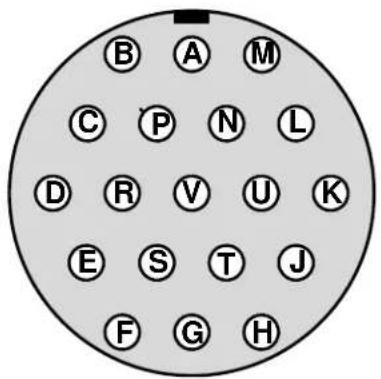
natural_image
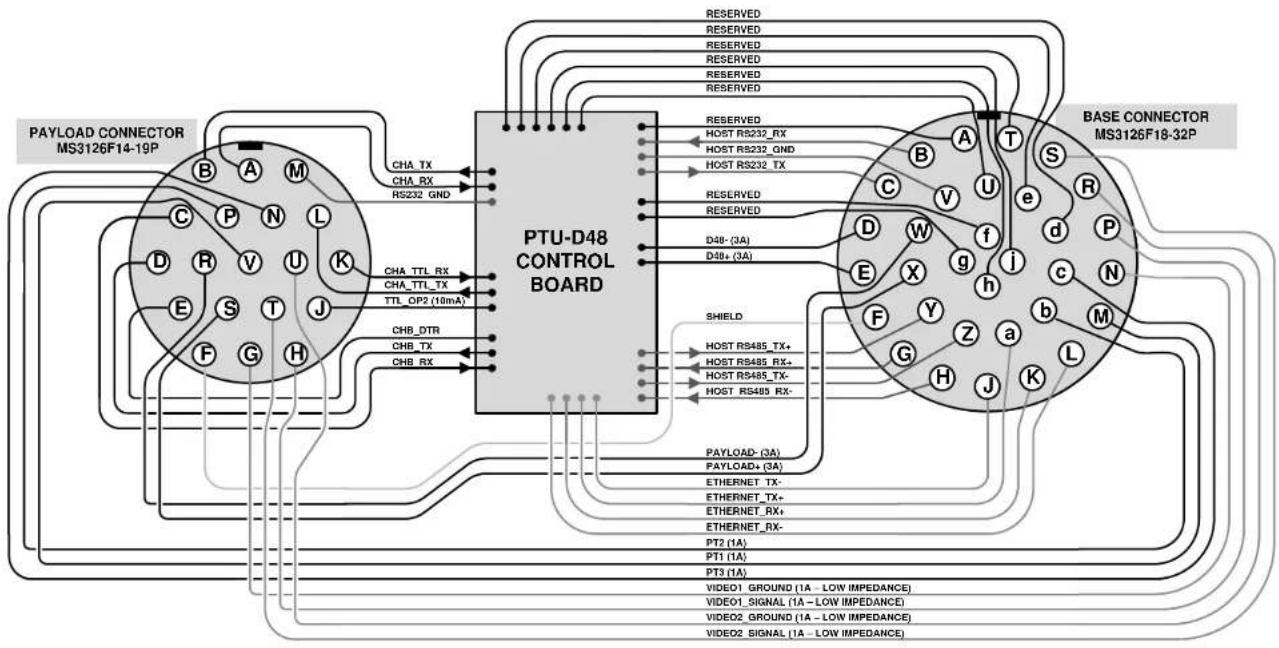
Close-up of a black electrical connector with a circular pinout and mounting holes (no visible text or symbols)A.3 - PL01 Wiring Diagram
Channel A RS-232 (CHA_TX and CHA_RX) and Channel A TTL (TTL_TX and TTL_RX) are mutually exclusive and operate at different voltage levels. Do not connect to both ports simultaneously. There are no TTL signals available for Channel B. The two video lines are specifically routed to have the least impedance of any payload lines; place any analog video lines along these payload lines.
PL01
flowchart
graph TD
    A["PTU-D48 CONTROL BOARD"] -->|CHA_TX, CHA_RX, RS232_GND| B["BASE CONNECTOR MS3126F18-32P"]
    A -->|D48_(3A), D48+(3A)| C["Base CONNECTOR MS3126F18-32P"]
    A -->|CHB_DTR, CHB_TX, CHB_RX| D["Base CONNECTOR MS3126F18-32P"]
    A -->|PAN L, TTL_OP2(10mA)| E["Base CONNECTOR MS3126F18-32P"]
    A -->|RESERVED, REST, GND, RS232_RX, RS232_GND, RS232_TX, RS232_RX, RS232_RX, RS232_RX, RS232_RX, RS232_RX, RS232_RX, RS232_RX, RS232_RX, RS232_RX, RS232_RX, RS232_RX, RS232_RX, RS232_RX, RS232_RX, RS232_RX, RS232_RX, RS232_RX, RS245_TX+ & RS485_RX+ & RS485_TX+ & RS485_RX- & RS485_RX- & RS485_RX+, & RS485_RX-, & RS485_RX-, & RS485_RX-, & RS485_RX-, & RS485_RX-, & RS485_RX-, & RS485_RX-, & RS485_RX-, & RS485_RX-, & RS485_RX-, & RS485_RX-, & RS485_RX-, & RS485_RX-, & RS485_RX-, & RS485_RX-, & PSGround_1 (A) & PSGround_1 (A) & PSGround_1 (A) & PSGround_1 (A) & PSGround_1 (A) & PSGround_1 (A) & PSGround_1 (A) & PSGround_1 (A) & PSGround_1 (A) & PSGround_1 (A) & PSGround_1 (A) & PSGround_1 (A) & PSGround_1 (A) & PSGround 1 (A) & PSGround 1 (A) & PSGround 1 (A) & PSGround 1 (A) & PSGround 1 (A) & PSGround 1 (A) & PSGround 1 (A) & PSGround 1 (A) & PSGround 1 (A) & PSGround 1 (A) & PSGround 1 (A) & PSGround 1 (A) & PSGround 1 (A)
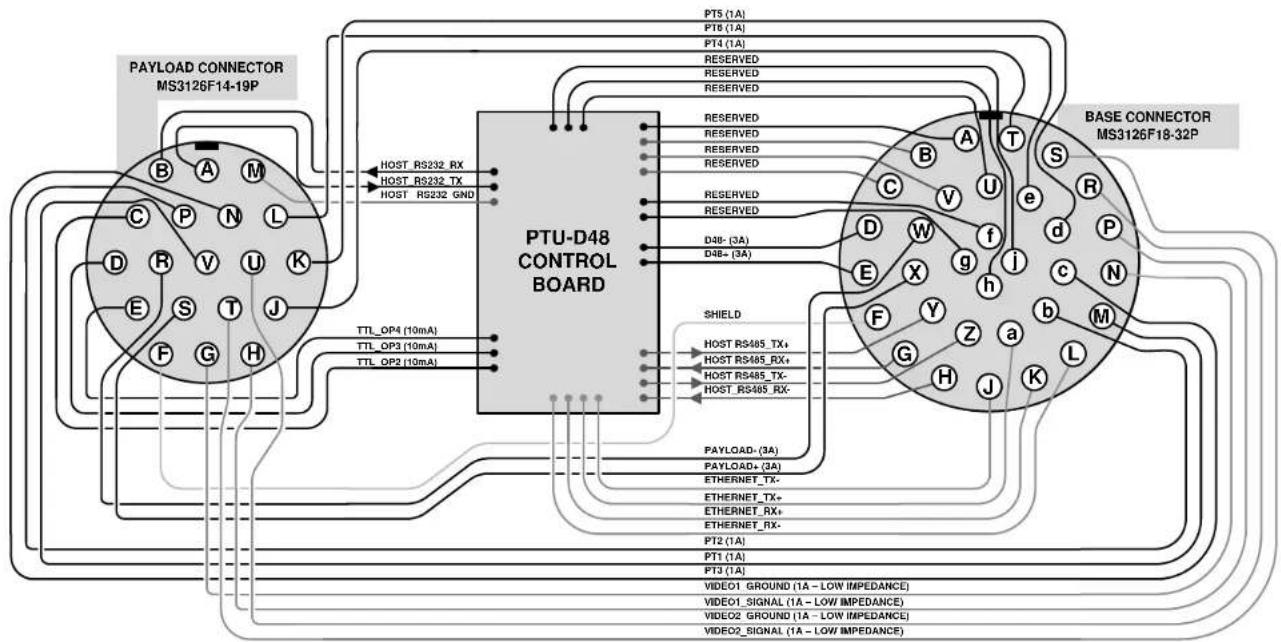
A.4 - PL02 Wiring Diagram
PL02 video lines are specifically routed to have the least impedance of any payload lines; place any analog video lines along these payload lines.
0
PL02
flowchart
graph TD
    subgraph_PTU-D48_CONTROL_BOARD["PTU-D48 CONTROL BOARD"]
        A["HOST_RS232_RX"] --> B["RESERVED"]
        C["HOST_RS232_TX"] --> D["RESERVED"]
        E["HOST_RS232_GND"] --> F["RESERVED"]
        G["D3B- (3A)"] --> H["RESERVED"]
        I["D4B+ (3A)"] --> J["RESERVED"]
        K["TTL_OP4 (10mA)"] --> L["TTL_OP3 (10mA)"]
        M["TTL_OP2 (10mA)"] --> N["TTL_OP1 (10mA)"]
    end

    subgraph_BASE_CONNECTOR["BASE CONNECTOR MS3126F18-32P"]
        O["PORTS (1A)"] --> P["RESERVED"]
        Q["PORT (1A)"] --> R["RESERVED"]
        S["PORT (1A)"] --> T["RESERVED"]
        U["PORT (1A)"] --> V["RESERVED"]
        W["PORT (1A)"] --> X["RESERVED"]
        Y["PORT (1A)"] --> Z["RESERVED"]
        AA["PORT (1A)"] --> AB["RESERVED"]
        AC["PORT (1A)"] --> AD["RESERVED"]
        AE["PORT (1A)"] --> AF["RESERVED"]
        AG["PORT (1A)"] --> AH["RESERVED"]
        AI["PORT (1A)"] --> AJ["RESERVED"]
        AK["PORT (1A)"] --> AL["RESERVED"]
        AM["PORT (1A)"] --> AN["RESERVED"]
        AO["PORT (1A)"] --> AP["RESERVED"]
        AQ["PORT (1A)"] --> AR["RESERVED"]
        AS["PORT (1A)"] --> AT["RESERVED"]
        AU["PORT (1A)"] --> AV["RESERVED"]
        AW["PORT (1A)"] --> AX["RESERVED"]
        AY["PORT (1A)"] --> AZ["RESERVED"]
        BA["PORT (1A)"] --> BB["RESERVED"]
        BC["PORT (1A)"] --> BD["RESERVED"]
        BE["PORT (1A)"] --> BF["RESERVED"]
        BG["PORT (1A)"] --> BH["RESERVED"]
        BI["PORT (1A)"] --> BJ["RESERVED"]
        BK["PORT (1A)"] --> BL["RESERVED"]
        BM["PORT (1A)"] --> BN["RESERVED"]
        BO["PORT (1A)"] --> BP["RESERVED"]
        BQ["PORT (1A)"] --> BR["RESERVED"]
        BS["PORT (1A)"] --> BT["RESERVED"]
        BU["PORT (1A)"] --> BV["RESERVED"]
        BW["PORT (1A)"] --> BX["RESERVED"]
        BY["PORT (1A)"] --> BYD["RESERVED"]
        BZ["PORT (1A)"] --> BZD["RESERVED"]
        CA["PORT (1A)"] --> CB["RESERVED"]
        CC["PORT (1A)"] --> CD["RESERVED"]
        CE["PORT (1A)"] --> CF["RESERVED"]
        GD["PORT (1A)"] --> GDY["RESERVED"]
        DH["PORT (1A)"] --> DHX["RESERVED"]
        DI["PORT (1A)"] --> DJ["RESERVED"]
        DK["PORT (1A)"] --> DL["RESERVED"]
        DV["PORT (1A)"] --> DVY["RESERVED"]
        DX["PORT (1A)"] --> DXY["RESERVED"]
        DXY --> DXZ["RESERVED"]
    end

    PTU-D48_CONTROL_BOARD --> SHIELD
    SHIELD --> PAYLOAD_*(3A)
    SHIELD --> PAYLOAD_*(3A)
    SHIELD --> ETHERNET_TX_*
    SHIELD --> ETHERNET_TX_*
    SHIELD --> ETHERNET_RX_*
    SHIELD --> ETHERNET_RX_*
    SHIELD --> PT2_*(1A)
    SHIELD --> PT1_*(1A)
    SHIELD --> PT3_*(1A)
    SHIELD --> VIDEO1_GROUND(1A - LOW IMPEDANCE)
    SHIELD --> VIDEO1_SIGNAL(1A - LOW IMPEDANCE)
    SHIELD --> VIDEO2_GROUND(1A - LOW IMPEDANCE)
    SHIELD --> VIDEO2_SIGNAL(1A - LOW IMPEDANCE)
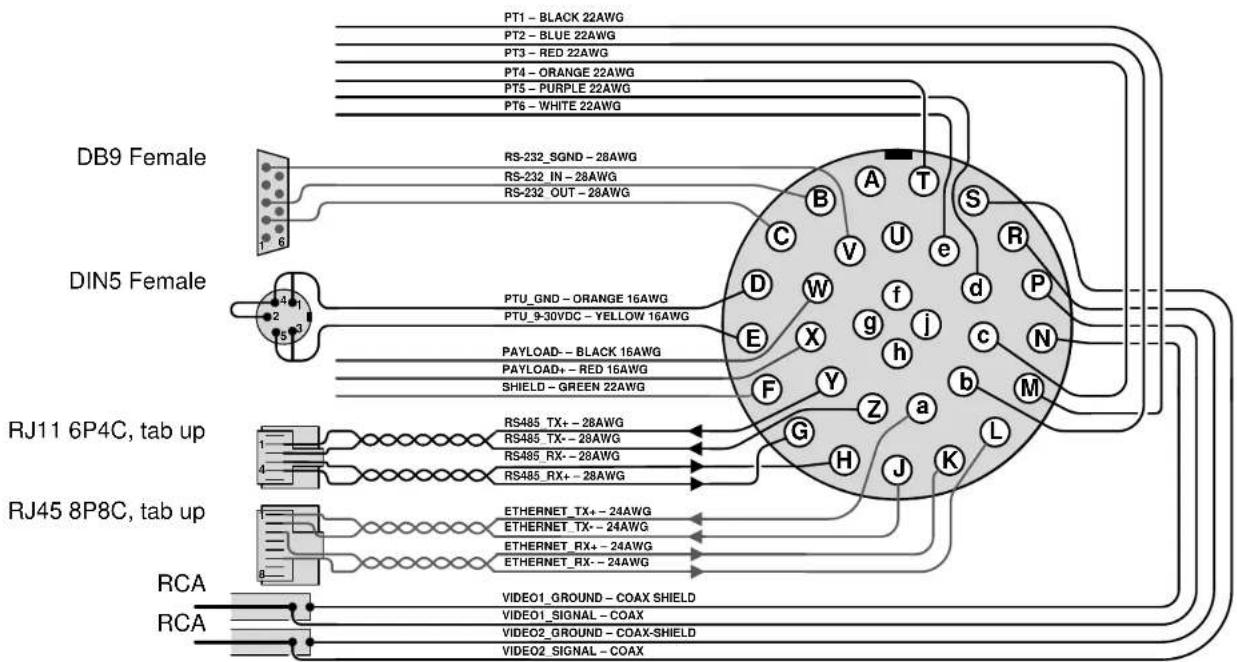
A.5 - 32-Pin Breakout Cable
This diagram displays the optional 32-pin breakout cable (PTU-CAB-E-25BO) wiring and connectors.
32-Pin Breakout Cable
Note: Some of the signals shown here may not be used in your configuration.
B. - Mechanical Drawings
The PTU-D48 can use side and/or top payload mounting brackets. This Appendix describes the payload mounting patterns for the different brackets and displays the PTU-D48 unit dimensions.
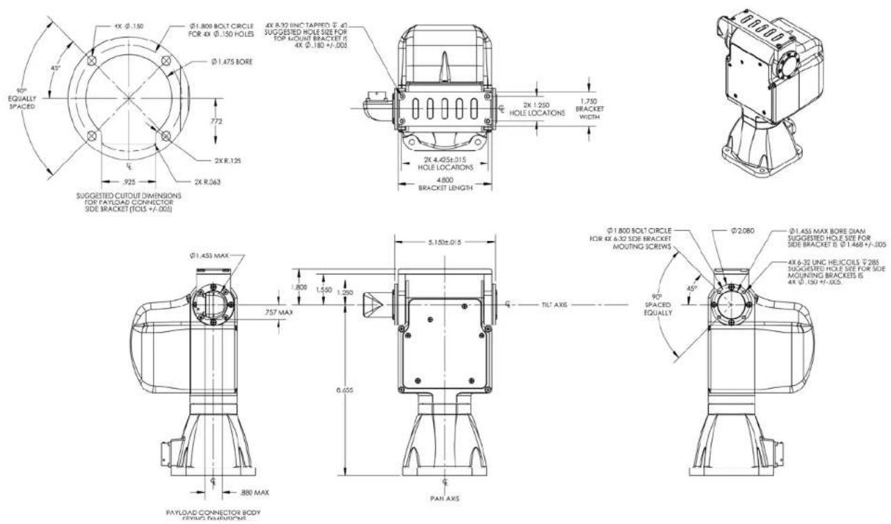
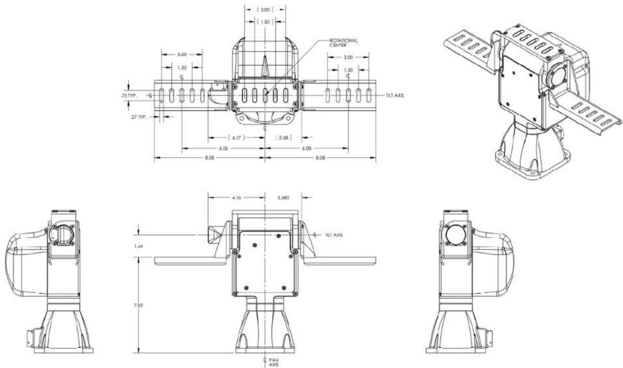
B.1 - Payload Mounting Pattern
The following images display the dimensions and mounting patterns for both the top and side brackets. The holes and bracket positions relative to the hub are identical for all mounting combinations.
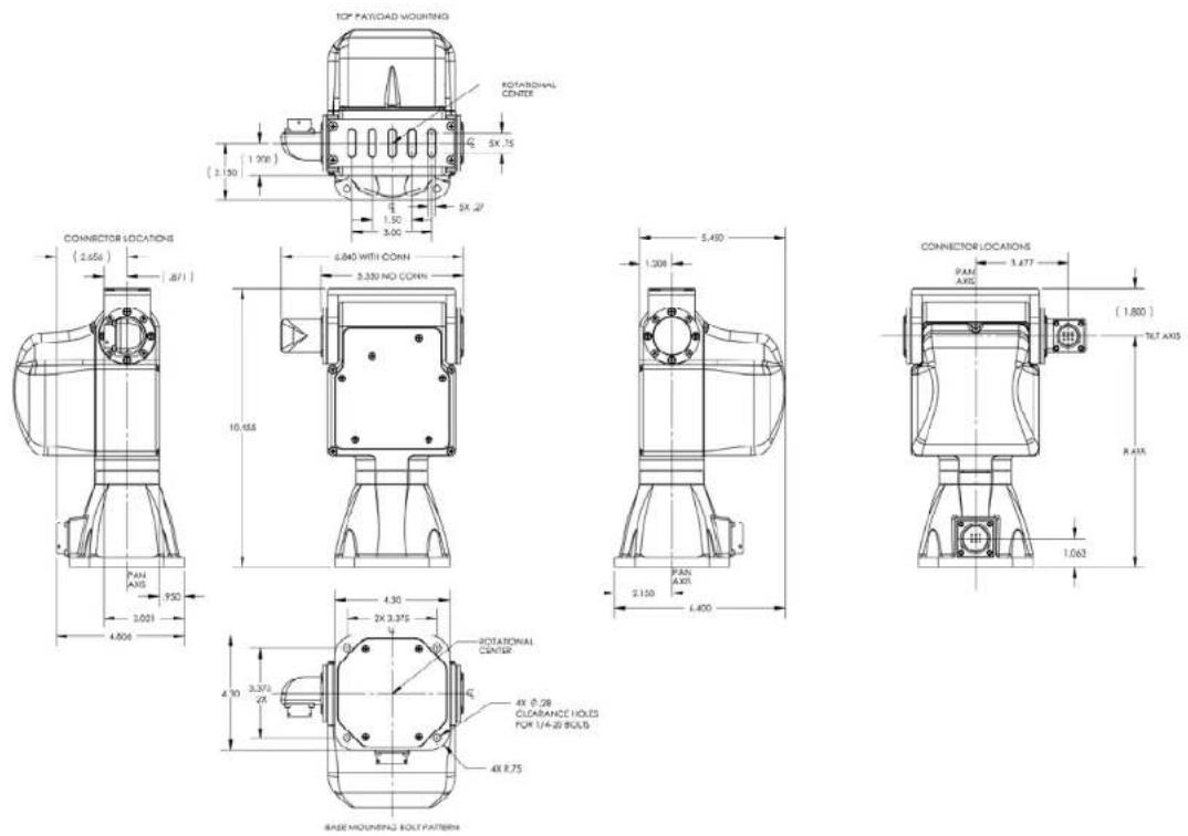
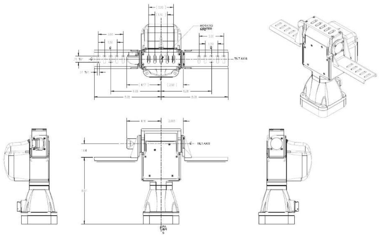
B.2 - PTU-D48 Dimensions (Standard)
This image displays the standard (non-ISM) PTU-D48 dimensions.
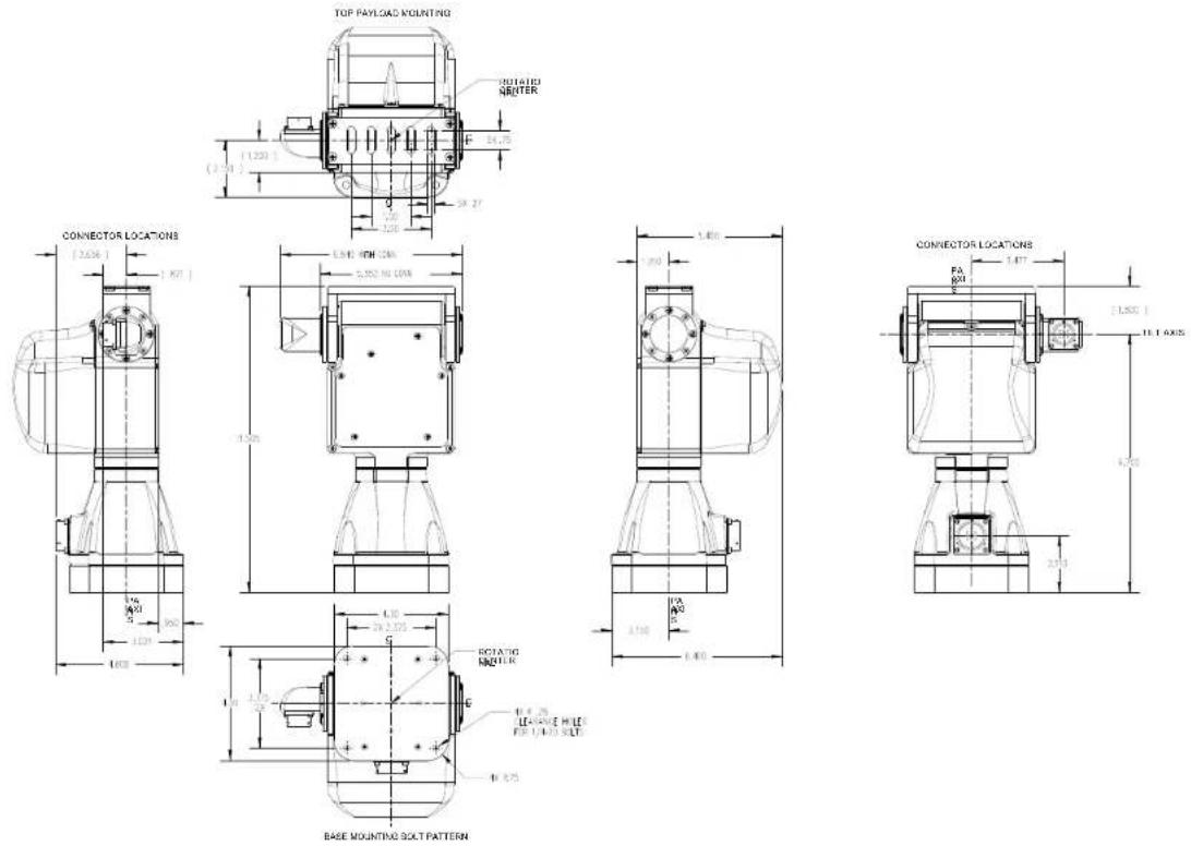
B.2 - PTU-D48 Dimensions (ISM)
This image displays the ISM-equipped PTU-D48 dimensions.
C. - Networking
This section describes the basic installation and setup steps required to network your pan-tilt units.
C.1 - Ethernet
To connect multiple PTU-D48 units to a single host computer via Ethernet:
- Plan the physical placement of each PTU-D48 and the host computer.
- Connect each PTU-D48 to your network using the Ethernet connection on each unit.
- On the host computer, run the PTU Finder utility to locate the PTU-D48 unit IP addresses.
- Launch a Web browser and point it to the IP address of the unit you want to connect to. You may open multiple browser windows/tabs to connect to multiple units at once.
Please see Section 3.4 for more information about connecting to a PTU-D48 using the Web interface.
C.2 - Serial
You may connect up to 127 PTU-D48 units to a single host computer port. The host computer can then address each connected PTU-D48 as if it were the only unit on the network. This makes it easy to migrate code developed for a single PTU-D48 to a network of PTU-D48 units controlled by one host computer.
To connect multiple PTU-D48 units to a single host computer via serial:
- Assign a unique network ID number to each PTU-D48.
- Connect the PTU-D48 units and host computer to the serial network.
- Test the configuration by addressing each PTU-D48 by its unit ID and issuing commands and queries.
C.2.1 - Serial Networking Connections
Multiple PTU-D48 units can be networked and connected to the host computer's RS-232 port. All network communications use RS-485, meaning that you must have an RS-232 to RS-485 adapter if the host computer does not directly support full-duplex RS-485 I/O. The host computer functions as the network host, meaning that its TX and RX lines define the directions of data traffic flow. Each PTU-D48 on the network is a client that communicates with the host using a full-duplex connection.
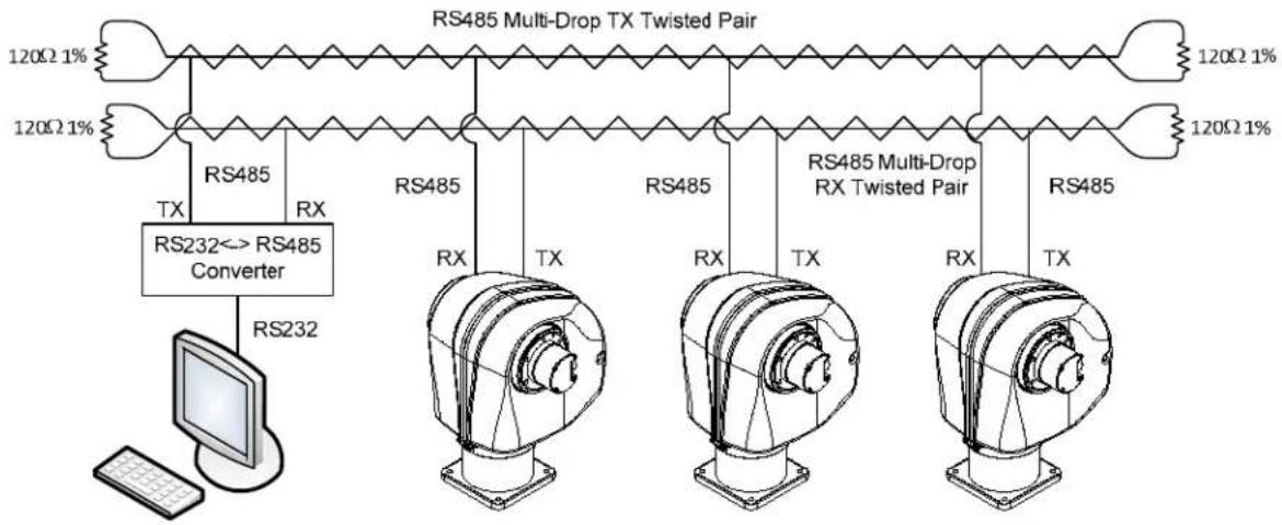
flowchart
graph TD
    A["120Ω 1%"] --> B["RS485 Multi-Drop TX Twisted Pair"]
    C["120Ω 1%"] --> D["RS485 Multi-Drop RX Twisted Pair"]
    E["RS232"] --> F["RS232<> RS485 Converter"]
    G["Computer"] --> H["RS232"]
    style A fill:#f9f,stroke:#333
    style C fill:#f9f,stroke:#333
    style E fill:#ccf,stroke:#333
    style G fill:#ccf,stroke:#333
    style B fill:#fff,stroke:#333
    style D fill:#fff,stroke:#333
    style F fill:#fff,stroke:#333
    style H fill:#fff,stroke:#333
    style G fill:#fff,stroke:#333
Figure 5: PTU Network Configuration
When making your own data cables, FLIR Motion Control Systems, Inc. recommends using a good quality twisted pair cable with about 100Ω impedance, which provides good noise immunity for RS-485 connections.
The following RS-232 to RS-485 converters are recommended:
- ATEN IC- 485S
- Moxa A50
Both adapters require a flipped RJ-12 connector (such as a standard phone cord).
Terminate the serial network by placing 120 Ω 1% resistors between the RS-485 Transmit+/Transmit- (Tx+/Tx-) and Receive+/Receive- (Rx+/Rx-) wires at each end of the network, as shown in Figure 5.
C.2.2 - ASCII Command Syntax
This section provides a brief overview of the ASCII command syntax. Please refer to the Pan-Tilt E Series Command Reference Manual for complete information and instructions.
The PTU-D48 uses both commands and queries. A command tells the PTU-D48 to do something (such as pan to a specific angle). A query asks the PTU-D48 to return the requested value (such as reporting the current pan angle).
The basic ASCII command syntax is
is the actual command (such as PP for pan position), is a numerical value (such as the desired pan position), and is a character used to denote the end of a command. Valid delimiter characters can be either [SPACE] or [ENTER].
The basic ASCII query syntax is
is the actual command (such as PP for pan position), is a character used to denote the end of a query. Valid delimiter characters can be either [SPACE] or [ENTER].
For example:
- Command: PP
sets the desired absolute pan position. - Query: PP
returns the current absolute pan position.
Commands and queries return results that display on the terminal screen, as follows:
- A successfully executed command displays * on the terminal screen.
- A successfully executed query displays
(where is the result of the query you just executed). - A failed command displays !
(where describes the error encountered). - A pan axis limit hit asynchronously displays !P.
- A tilt axis limit hit asynchronously displays !T.
This sample command sequence pans the PTU-D48 to the left, waits, and then pans it back to the right:
S
PP-2500 *
A *
PP * Current Pan position is -2500
PP2500 *
A *
PP * Current Pan position is 2500
C.2.3 - Serial Command List
These tables list the most commonly used serial commands. Please refer to the Pan-Tilt E Series Command Reference Manual for complete information about the available commands and their usage.
LIMITS
| CMD | DESCRIPTION | CMD | DESCRIPTION |
| PN | Minimum pan position | L | Query limit status |
| PX | Maximum pan position | LE | Enable limits |
| TN | Minimum tilt position | LD | Disable limits |
| TX | Maximum tilt position | LU | User limits |
POSITION
| CMD | DESCRIPTION | CMD | DESCRIPTION |
| PP | Pan position | PR | Pan resolution |
| TP | Tilt position | TR | Tilt resolution |
| PO | Pan offset | ||
| TO | Tilt offset | ||
SPEED
| CMD | DESCRIPTION | CMD | DESCRIPTION | CMD | DESCRIPTION |
| PS | Pan speed | PA | Pan acceleration | PU | Pan upper speed |
| TS | Tilt speed | TA | Tilt acceleration | PL | Pan lower speed |
| PD | Pan speed offset | PB | Pan base speed | TU | Tilt upper speed |
| TD | Tilt speed offset | TB | Tilt base speed | TL | Tilt lower speed |
MISCELLANEOUS
| CMD | DESCRIPTION |
| A | Await |
| R | Reset |
| DF | Restore factory defaults |
| H | Halt |
D. -Troubleshooting
This appendix presents common mechanical, power, and networking challenges and resolutions, and also provides information about contacting FLIR MCS Technical Support.
D.1 - Mechanical
After powering on, the PTU-D48 stops moving with a grinding noise.
• If you have a payload attached:
- The payload may be too heavy. Try moving the payload closer to the center of rotation of the affected axis and/or reducing the payload weight.
- The movement settings may be too aggressive. Reduce the upper speed limit and/or acceleration.
- If you do not have a payload attached, contact FLIR MCS Technical Support.
D.2 - Power
The PTU-D48 E Series reset movements are different than older PTU-D48 models.
• This is normal behavior.
D.3 - Networking
Unable to determine the PTU-D48 IP address to access the onboard Web page.
- If you are running Windows, use the PTU Finder tool included on the CD that shipped with your PTU-D48.
- If you are not running Windows, ttach a serial device to the PTU-D48 host port and then issue the NI command to query the IP address of the PTU-D48.
PTU-D48 Web page controls are sluggish.
- Adjust the speeds and/or step size by clicking the Set Arrow Step Size or Set Arrow Speed headers in the PTU Control Web page, as described in Section 6.3
- Try closing other programs on your computer to free up resources.
Unable to establish serial communications with the PTU-D48.
• If you are using RS-232:
- Make sure that the PTU-D48 is equipped with RS-232 communications at the port you are using. Units with PL01 wiring have RS-232 at the base, while units with PL02 wiring have RS-232 at the payload port.
■ Try using a null-modem adapter. - If you are using a laptop, make sure that it is plugged in. RS-232 will not work if the PTU-D48 and host computer grounds are too far apart.
- Verify that the RS-232 port is working using a loop-back adapter. If you do not have a loop-back adapter, connect pins 2 and 3 of the DB-9 RS-232 connector. Any characters typed into the serial terminal should be echoed back when the loop-back adapter is attached.
- If you are using the RS-232 to RS-485 adapter provided by FLIR Motion Control Systems:
■ Set the switches to T RxON and DCE.
■ Make sure the adapter is powered.
■ Try using a null-modem adapter
If you are using a laptop, make sure that it is plugged in. RS-232 will not work if the PTU-D48 and host computer grounds are too far apart.
- Verify that the RS-232 port is working using a loop-back adapter. If you do not have a loop-back adapter, connect pins 2 and 3 of the DB-9 RS-232 connector. Any characters typed into the serial terminal should be echoed back when the loop-back adapter is attached.
D.4 - Technical Support
FLIR Motion Control Systems, Inc. provides a range of technical support options to ensure that your project is a success. To access Technical Support:
- Visit the Support section at www.FLIR.com/MCS.
- Email Technical Support at MCS-support@FLIR.com.
• Call (650)692-3900 and select Technical Support.
Email is the preferred method of obtaining support to help ensure proper dispatching and tracking to address your questions promptly. When emailing Technical Support, please provide the following information:
• PTU model and configuration
- Payload information, including photos
• Parameter settings
• Detailed issue/symptom description
This page intentionally left blank.
E. - Regulatory Information
Electromagnetic Interference (EMI) is any signal or emission, either radiated in free space or conducted along power or signal leads, that endangers the function of a radio navigation or other safety service or that seriously degrades, obstructs, or repeatedly interrupts a licensed radio communications service.
Class A
Class A equipment has been tested and found to comply with the limits for a Class A digital device, pursuant to Part 15 of the FCC Rules. These limits are designed to provide reasonable protection against harmful interference in a commercial environment. This equipment generates, uses, and can radiate radio frequency energy and, if not installed and used in accordance with the instructions, may cause harmful interference to radio communications. However, there is no guarantee that interference will not occur in a particular installation. Operation of this equipment in a residential area is likely to cause harmful interference, in which case the user will be required to correct the interference at his/her own expense.
Caution: Changes or modifications of this equipment not expressly approved by manufacturer could result in violation of Part 15 of the Federal Communication Commission's rules. The FCC has prepared the following booklet: "How to Identify and Resolve Radio-TV Interference Problems." It is available from the US Government Printing Office, Washington DC, 20402. Stock Number 004-00-00345-4.
FCC Notice
According to 47CFR, Parts 2 and 15, Subpart B Class A:
This device complies with FCC Part 15, Subpart B Class A of the FCC Rules. Operation is subject to the following two conditions: (1) This device may not cause harmful interference, (2) This device must accept any interference received including interference that may cause undesired operations.
CE Notice
This is a Class A product. In a domestic environment, this product may cause radio interference, in which case the user may be required to take adequate measures.
ABOUT FLIR MOTION CONTROL SYSTEMS
FLIR Motion Control Systems, Inc. (formerly Directed Perception) is a leading manufacturer of innovative devices and software for the intelligent control of sensors and sensor processing. In 1992, FLIR MCS created one of the first miniature computer-controlled pan/tilt tracking mounts and continues to lead the field in innovation, applied design, and service. Our patented pant/tilt units are in use in a wide range of industries including security and surveillance, industrial automation, robotics, communications, military/aerospace, law enforcement, education, R&D, webcams, and teleconferencing/distance learning applications. Some of the payloads that can be precisely controlled include sensors like video cameras, thermal imagers, laser rangefinders, microwave antennas, and many more. FLIR MCS maintains engineering capabilities in mechanical design, electronics, and embedded and network software development. Find out more at www.FLIR.com/mcs.
ABOUT FLIR SYSTEMS, INC.
FLIR Systems, Inc. is the world's largest commercial infrared company with the more high quality thermal night vision systems in the field than all other manufacturers combined. Our rugged, stabilized imagers are on thousands of civil and military surface and airborne platforms in the USA and around the world.
With thousands of our thermal cameras on the job in military, scientific, law enforcement, and security applications, FLIR brings an unmatched level of experience and dedication to the creation of cutting edge thermal night vision systems.
We design and manufacture all of the critical technologies inside our products, including detectors, electronics, special lenses, and pan/tilt motion control systems. All of our products are proudly assembled right here in the USA.
For additional technical information, or to see a demonstration of these revolutionary thermal night vision systems, contact a FLIR representative today. You can also visit www.FLIR.com to watch product videos and see how thermal imaging can help you see night and day.
LIMITED WARRANTY
FLIR Motion Control Systems, Inc. warrants this product against defects in material or workmanship, as follows:
For a period of one year from date of purchase, FLIR Motion Control Systems, Inc. will repair the defective product and provide new or rebuilt replacements at no charge. Warranty repairs require the issuance of a repair authorization number from FLIR Motion Control Systems prior to the return of merchandise, and the buyer assumes responsibility for freight charges.
After the one year period, the purchaser must pay for all parts, labor, and freight.
This warranty does not cover any damage due to accident, misuse, abuse, or negligence. You should retain your original bill of sale as evidence of the date of purchase.
REPAIR OR REPLACEMENT AS PROVIDED UNDER THIS WARRANTY IS THE EXCLUSIVE REMEDY OF THE PURCHASER. FLIR MOTION CONTROL SYSTEMS, INC. SHALL NOT BE LIABLE FOR ANY INCIDENTAL OR CONSEQUENTIAL DAMAGES FOR BREACH OF ANY EXPRESS OR IMPLIED WARRANTY ON THIS PRODUCT, EXCEPT TO THE EXTENT PROHIBITED BY APPLICABLE LAW, ANY IMPLIED WARRANTY OF MERCHANTABILITY OR FITNESS FOR A PARTICULAR PURPOSE ON THIS PRODUCT IS LIMITED IN DURATION TO THE DURATION OF THIS WARRANTY.
Some states do not allow the exclusion or limitation of incidental or consequential damages, or allow limitations on how long an implied warranty lasts, so the above limitations or exclusion may not apply to you. This warranty gives you specific legal rights, and you may also have other rights which vary from state to state.
PTU-D48 E Series User Manual v. 4.20 (01/2011)

FLIR®
Motion Control Systems
890C Cowan Road
Burlingame, CA 94010
p: (650)692-3900
f: (650)692-3930
www.FLIR.com/MCS