ServerSwitchIQ SSIQ24P2U-2-XE - Security Camera Razberi - Free user manual and instructions
Find the device manual for free ServerSwitchIQ SSIQ24P2U-2-XE Razberi in PDF.

User questions about ServerSwitchIQ SSIQ24P2U-2-XE Razberi
0 question about this device. Answer the ones you know or ask your own.
Ask a new question about this device
Download the instructions for your Security Camera in PDF format for free! Find your manual ServerSwitchIQ SSIQ24P2U-2-XE - Razberi and take your electronic device back in hand. On this page are published all the documents necessary for the use of your device. ServerSwitchIQ SSIQ24P2U-2-XE by Razberi.
USER MANUAL ServerSwitchIQ SSIQ24P2U-2-XE Razberi
For the ServerSwitchIQ Portfolio of Razberi Appliances October 2018 V1.8
Table of Contents
1| QUICK START GUIDE....4
1.1 INTRODUCTION....4
1.1.1 About This Document 4
1.1.1.1 Qualified User Profile and Assumptions 4
1.1.2 About the Razberi ServerSwitchIQ Product Portfolio ....4
1.2 VERIFY PACKAGE CONTENTS....6
1.2.1 Package Contents....6
1.2.2 Quick Start Guides....6
1.3 UNDERSTANDING YOUR RAZBERI™ 6
1.3.1 Embedded VLAN....7
1.3.2 The 95% Rule (Reducing Bandwidth and IP Proliferation)....7
1.3.3 Web-based Switch Interface 8
1.3.4 LED Operational Information 9
1.3.5 Connecting to the Corporate Network (Edge Recording and U2)....10
1.4 INITIAL STARTUP....11
1.4.1 Identifying Your Product....11
1.4.2 Securing the Appliance via Mounting Equipment 13
1.4.3 Connecting Hardware (Keyboard, Monitor, Mouse) 14
1.4.4 Creating User Logins and User Accounts (Admin, Service Personnel, etc.) 14
1.4.5 Configuring RAID (Select Models)....14
1.4.6 NVIDIA GPU (Select Models) 15
1.4.7 Switch (U1) and Server (U2) Network Configuration....15
1.5 CONNECTING CAMERAS, VMS SELECTION AND INSTALLATION....15
1.6 CAMERADEFENSE....16
1.7 RAZBERI MONITOR™ HEALTH MONITORING....16
2| SWITCH MANAGEMENT ....18
2.0.1 Navigation Bar 18
2.1 OVERVIEW PAGE....18
2.1.1 System Information....19
2.1.2 Resource Usage....20
2.1.3 Port Status....20
2.2 POE PAGE 22
2.2.1 PoE Status....22
2.2.2 PoE Administration....23
2.3 DEVICE BINDING PAGE....25
2.3.1 Device Binding Administration....25
2.3.2 MAC Status (Legend) 26
2.3.3 How to Activate Device Binding 27
2.3.4 How to Add New Devices / MACs to Device Binding 28
2.3.5 How to Remove Devices / MACs from Device Binding 28
2.3.6 How to Identify and Remove Unauthorized MAC Address' 28
2.3.7 Examples of How Device Binding Works 29
2.4 VLAN PAGE 30
2.5 HTTPS....32
2.5.1 HTTPS Administration 32
2.5.2 Manage Certificate....32
2.5.3 Current Certificate Information....33
2.6 NETWORK PAGE....34
2.6.1 Switch Configuration....34
2.6.2 DHCP Server 36
2.6.3 Device Address Resolution....37
2.7 CAMERADEFENSE™ PAGE 39
2.7.1 Introduction....39
2.7.2 CameraDefense Included in Select Models....39
2.7.3 CameraDefense Setup Wizard....39
Introduction: 39
Device Binding: 40
Device Groups: 41
Activating the Embedded Firewall: 42
Whitelist: 43
Password Protection: 43
Review: 44
2.7.3 CameraDefense Dashboard....45
Changing Device Configurations: 45
Meanings of the Red, Yellow, Green and Alert Dashboard Status: 46
2.8 ADMIN PAGE 48
2.8.1 Security....48
2.8.2 Maintenance....49
2.8.3 Settings....50
2.8.4 Firmware 50
2.8.5 License 51
2.8.6 Razberi Monitor....51
2.9 SETUP WIZARD....52
2.9.1 U1, U2, and SFP 2 Network Setup ....53
2.9.2 Switch Configuration....54
2.9.3 Product Registration....55
2.9.4 Razberi MonitorCloud ^TM Account Registration ....55
2.9.5 VMS Installation....56
3| SERVER MANAGEMENT....57
3.1 SERVER ANTI-VIRUS SOFTWARE....57
3.1.1 Validating Cylance Installation....58
3.1.2 Receiving Cylance PROTECT® Updates....58
3.1.3 Receiving Cylance PROTECT® Malware Alerts....59
3.1.4 Authorizing Quarantined Files, Scripts, Services 59
4| ENDPOINTDEFENDER....60
4.1 ENDPOINTDEFENDER PRODUCT OVERVIEW....60
4.1.1 Network Protocol and Port Requirements 60
5| APPENDIX....61
5.1 APPENDIX A: FREQUENTLY ASKED QUESTIONS (FAQ)....61
5.1.1 General Questions....61
5.1.2 Video Management Software (VMS) 61
5.1.3 Operating System....62
5.1.4 Cameras and Video 63
5.1.5 Redundant Array of Independent/Inexpensive Disks (RAID) 63
5.1.6 Power Supply....64
5.1.7 Power over Ethernet (PoE) 64
5.1.8 Uplink Ports 65
5.1.9 Razberi MonitorCloud 66
5.1.9 CameraDefense and Cylance....67
5.1.9 EndpointDefender 68
5.2 APPENDIX B: NETWORK CONFIGURATION TYPES ....70
5.2.0.1 Distributed vs. Generalized Installations – Overview 70
5.2.1 Centralized Configuration 70
5.2.2 Distributed Configuration....72
5.2.2.1 Examples of Distributed Configurations....73
1| Quick Start Guide
Congratulations on choosing the innovative ServerSwitchIQ portfolio of surveillance appliances from Razberi Technologies!
This chapter will get you started quickly. Chapters 2, 3 and 4 provide a more detailed and leisurely overview of the products covered. Chapter 5 is the appendix; it includes frequently asked questions (FAQs), as well as system configuration examples.
The information within this version of the User Guide is designed to work with the latest features and enhancements available via ServerSwitchIQ firmware version 1.9 and higher and Razberi Monitor and Razberi MonitorCloud version 2.4.0 and higher. Please ensure you have these versions of firmware and software running to enjoy all the features outlined in this guide.
1.1 Introduction
The following sections of this chapter briefly define the scope of this document and help you get your system set up and running.
1.1.1 About This Document
This user guide is designed to ensure that you, the qualified user, can identify and successfully use all the functionality of the ServerSwitchIQ products applicable to your objectives.
This chapter will help familiarize you with your new ServerSwitchIQ product and its functions.
1.1.1.1 QUALIFIED USER PROFILE AND ASSUMPTIONS
This document assumes the user has the following qualifications:
• Understands basic networking and the use of static and dynamic IP addressing.
• Understands Power Over Ethernet (PoE).
- Is familiar with the operation and management of devices that will be attached to the ServerSwitchIQ switch, such as cameras and how to configure them.
• Is a competent user of Windows administration.
• Manages VMS software and understands how the VMS software controls devices.
1.1.2 About the Razberi ServerSwitchIQ Product Portfolio
Razberi has four classes of ServerSwitchIQ products designed to address a wide range of users and use cases as follows:
- ServerSwitchIQ - A ServerSwitch for edge recording that provides video-surveillance-class storage.
- ServerSwitchIQ Professional - A ServerSwitch for edge recording and local video viewing from HDMI output providing video surveillance-class storage.
- ServerSwitchIQ Enterprise - A ServerSwitchIQ for datacenter recording that provides enterprise-class storage in addition to local viewing from HDMI output.
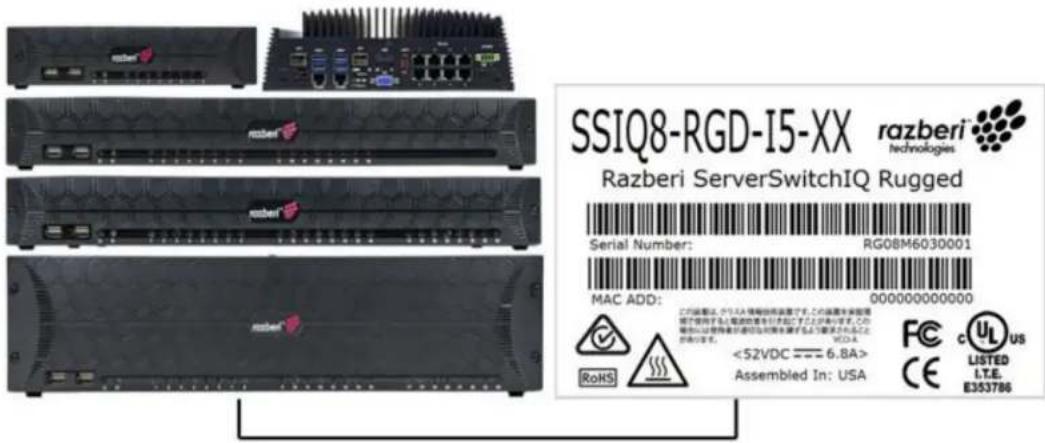
- ServerSwitchIQ Rugged - A ServerSwitchIQ with extended operating temperatures and solid-state storage.

natural_image
Black industrial heat exchanger with visible cooling fins and a brand logo (razberi Technologies) on the side panel.
natural_image
Close-up of a black electronic device rear panel with indicator lights and ports (no readable text or symbols)
natural_image
Close-up of a black electronic device with hexagonal patterns and red indicator lights (no readable text or symbols)
natural_image
Close-up of a black hexagonal grid device with red LED indicators and a small white object on the side (no visible text or symbols)Product Versions
Product versions covered by this user guide are ServerSwitchIQ, Pro, Enterprise, and Rugged versions. Please check the product specification sheets online at http://www.razberi.net for the latest information on these products.
1.2 Verify Package Contents
Upon receipt of your Razberi ServerSwitchIQ, make sure you have received all the contents as described below.
1.2.1 Package Contents
- Quick Start Guide (instruction sheet)
- Rack ears or rack mounting hardware (for 16 and 24 port units)
- Shelf or DIN rail mount hardware (for 8 and rugged units)
• ServerSwitchIQ device
• Power cord (for most countries)
- External power supply (8 port unit only). External power supplies for the rugged unit are sold separately.
1.2.2 Quick Start Guides
Each Razberi unit is packaged with a Quick Start Guide. An example of these guides is shown below.
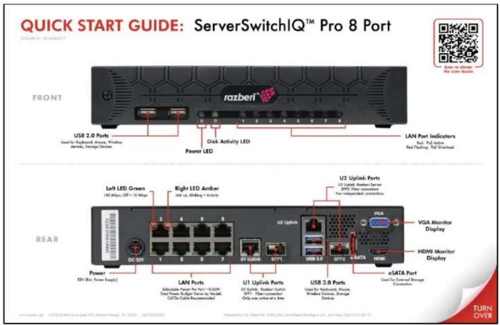
text_image
QUICK START GUIDE: ServerSwitchIQ™ Pro 8 Port FRONT razberi USB 2.0 Ports Used for Keyboard, Mouse, Windows Devices, Storage Devices. Disk Activity LED Power LED LAN Port Indicators Red Put Active Red Flashing Put Overload Left LED Green 100 Mbps, OFF + 10 Mbps Right LED Amber Link up, Bliding → Activity U2 Uplink Ports U2 Uplink: Random Server SP2: Fiber connection Two independent connections VGA Monitor Display HDMI Monitor Display Power 25V (Ex. Power Supply) LAN Ports Selectable Power For Port = 0.320V Total Power Budget Varies by Model CATTx Cable Recommended U1 Uplink SP1: Fiber connection Only one active at a line USB 3.0 SP2: eSATA Port Used for External Storage Connection eSATA Port USED by U.S. Wireless, WiFi, WiFi, and Power Pending in U.S. Ordering USB 10.0.10.19 TURN OVER1.3 Understanding Your Razberi™
The Razberi ServerSwitchIQ is the next generation of all-in-one, intelligent video surveillance appliances. Built for security, engineered for performance, open architected and optimized to
reduce impact on the IP network. The Razberi portfolio represents a complete suite of appliances that provide security leaders unmatched network video recording, scalability, and reliability, with cloud-based health monitoring and cyber security features.
• Patented, all-in-one appliances, much more than an NVR or general-purpose server
• Complete suite of scalable appliances that work enterprise-wide to the oil field
- Reduce megapixel camera impact on IP networks by up to 95%
• Intelligent, cloud-based features (VyneWatch) for health monitoring and cyber security
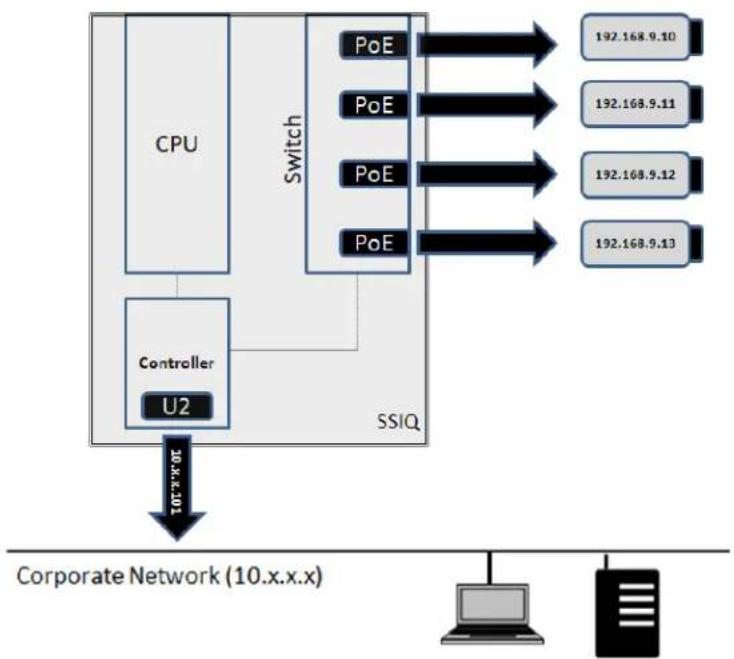
1.3.1 Embedded VLAN
Because of the ServerSwitchIQ's ability to segregate traffic on the switch from the network used to access the server, the ServerSwitchIQ acts as an embedded VLAN. Security cameras and related traffic managed by the switch (PoE ports and U1 network connections) are not shared with the U2 connection to the server. Users on the network accessing the server via U2 cannot directly access devices or data operating on the PoE ports or U1. Only the VMS or similar software can access devices connected to the switch via a client to server relationship.
flowchart
graph TD
    A["CPU"] --> B["Controller U2"]
    B --> C["SSIQ"]
    D["Switch"] --> E["192.168.9.10"]
    D --> F["192.168.9.11"]
    D --> G["192.168.9.12"]
    D --> H["192.168.9.13"]
    E --> I["Corporate Network (10.x.x.x)"]
    F --> I
    G --> I
    H --> I
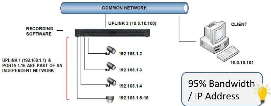
1.3.2 The 95% Rule (Reducing Bandwidth and IP Proliferation)
The embedded VLAN capability of the ServerSwitchIQ dramatically reduces the traffic of security applications on the corporate network, limiting it to live views and related VMS software activities.
The image below shows how security data and management of IP addresses are managed separately on an independent network, while providing the Video Management Software (VMS) exclusive access to security video. VMS clients can access the VMS recording software from a separate internal and independent network (shown as 192.168.1.X), thereby reducing network traffic and IP proliferation by as much as 95% when compared with traditional implementations where the VMS software must reside on the corporate network (shown as 10.0.10.X) and interact with video cameras.
flowchart
graph TD
    A["COMMON NETWORK"] --> B["UPLINK 2 (10.0.10.100)"]
    B --> C["192.168.1.2"]
    B --> D["192.168.1.3"]
    B --> E["192.168.1.4"]
    B --> F["192.168.1.5-16"]
    G["RECORDING SOFTWARE"] --> C
    H["CLIENT"] --> I["10.0.10.101"]
    J["95% Bandwidth / IP Address"] --> K["Lightbulb icon"]
1.3.3 Web-based Switch Interface
Your Razberi allows you to perform basic switch configurations using a web-based interface accessed directly from the unit or via an interconnected PC.
When you initially start your Razberi, the switch's IP address is set to a factory default of 192.168.50.1. Using the server's browser, you can open the web interface by simply typing in http://192.168.50.1. The factory default login is username: admin with password: system. Later sections of this manual provide more details regarding how to manage and monitor the switch using this interface. You will be asked to change this default password upon initial login. Save this in a safe place for future reference along with a back-up of the switch's configuration settings. If you lose the password to the switch interface, you can perform a "Reset Factory Default" of the switch by opening the Setup Wizard and selecting the Switch Configuration tab. Once you are back in the switch, you can restore its backup configuration settings.

flowchart
graph LR
    A["KVM"] --> B["Switch"]
    B --> C["Common Network"]
    D["Controller U2"] --> B
    E["CPU"] --> B
    F["Switch"] --> B
    G["192.168.50.1"] --> B
    H["PC"] --> I["192.168.50.x 255.255.255.0"]
1.3.4 LED Operational Information
The tables below describe the status conditions of the various light emitting diode (LED) lights on the front and back of your Razberi.
LAN RJ45 Connector LED Information - The image and table below shows the LED information for the LAN RJ45 connectors:
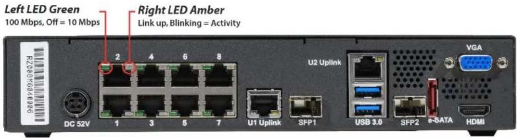
text_image
Left LED Green 100 Mbps, Off = 10 Mbps Right LED Amber Link up, Blinking = Activity 2 4 6 8 DC 52V 1 3 5 7 U2 Uplink U1 Uplink SFP1 USB 3.0 SFP2 e-SATA VGA HDMI| LED | STATUS |
| LEFT LED DATA RATE INDICATOR | OFF – 10 MBPS data rate selected |
| GREEN – 100 MBPS data rate selected | |
| ORANGE – 1000 MBPS data rate selected (U1 Only) | |
| RIGHT LED LINK STATUS INDICATOR | OFF – LAN link not established |
| AMBER ON – LAN link established | |
| AMBER BLINKING – LAN activity is occurring |
PoE Port LED Information:

text_image
1 2 3 4 5 6 7 8| LED | STATUS |
| PoE LED | OFF – PoE not provided |
| RED ON – PoE provided | |
| RED BLINKING – PoE overloaded |
The two LEDs on the left are the Power and Disk Activity lights. When the unit is powered, the Power LED will be on. Disk activity will be indicated by a flickering amber light.
1.3.5 Connecting to the Corporate Network (Edge Recording and U2)
The most common approach to using your Razberi is to connect cameras and other security devices to the PoE ports. This isolates and secures video traffic from your corporate network while providing access to the stored video via U2's connection.

flowchart
graph TD
    subgraph Top_1
        A["CPU"] --> B["Controller U2"]
        C["Switch"] --> B
        B --> D["SSIQ"]
    end
    subgraph Middle_1
        E["CPU"] --> F["Controller U2"]
        G["Switch"] --> F
        F --> H["SSIQ"]
    end
    subgraph Bottom_1
        I["CPU"] --> J["Controller U2"]
        K["Switch"] --> J
        J --> L["SSIQ"]
    end
SSIQ reduces unnecessary bandwidth usage while also limiting direct access to the internal camera network.
Corporate Network (10.x.x.x)
1.4 Initial Startup
The following sections will help you get started.
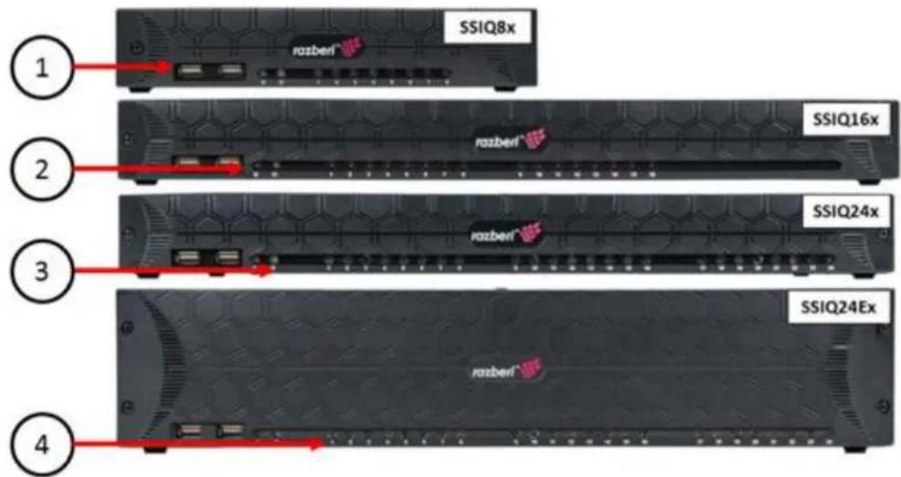
1.4.1 Identifying Your Product
Located at the bottom of every SSIQ appliance is serial / model label detailing all the information needed to identify SSIQ model.

FRONT VIEW
text_image
SSIQ8x 1 2 3 4 SSIQ16x SSIQ24x SSIQ24Ex- USB 2.0 Connectors
- System Power LED
- Disk Activity LED
- PoE Status LEDs
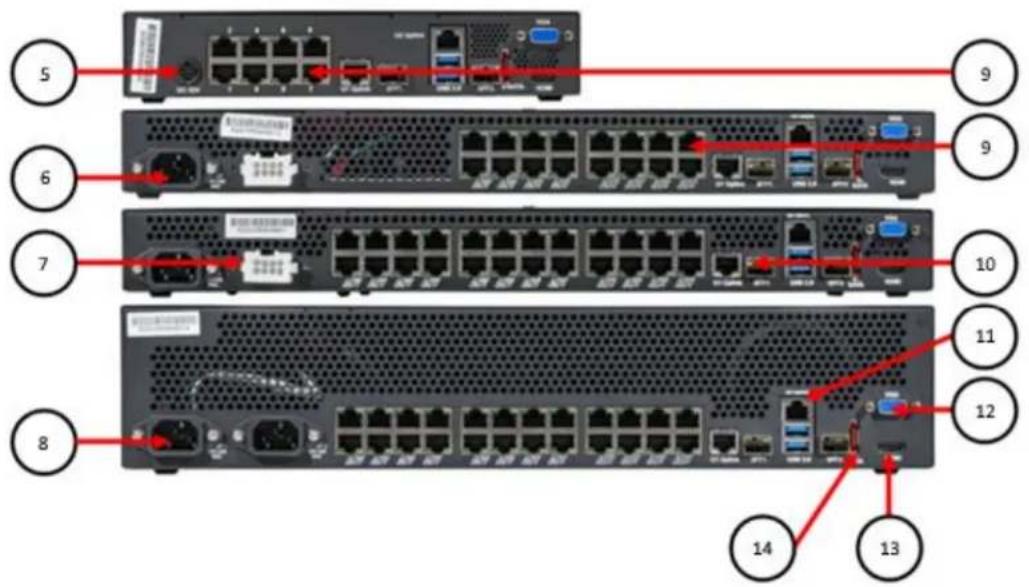
REAR VIEW
text_image
5 6 7 8 9 9 10 11 12 13 14-
DC Power Input Connector
-
AC Power Input Connector
-
External Redundant Power (SSIQ24E)
-
Internal Redundant Power (SSIQ24E2U)
-
PoE Ports
-
U1 Switch Uplink
-
U2 Server Network
-
VGA Monitor Connector
-
HDMI Monitor Connector
-
eSATA Connector
1.4.2 Securing the Appliance via Mounting Equipment
The Razberi appliance comes with rack and wall mounting hardware based on the model. As appropriate, mount your hardware according to the following instructions.
- 8 Port units come with two wall mount brackets for securing the 8 port unit to a wall, desk, or other structure. The brackets come with four screws that replace the two existing screws on each side of the unit. Simply align the brackets with the two mounting screws on the side of the unit, remove, replace, and tighten the screws, and mount the unit on the wall or similar structure.
- 16/24 port 1U (single height) units have two mounting options that use two rack ear mounts.
-
Front Mount Option: Begin by removing the five screws on the front of each side of the unit. Next, align the five holes of the unit with the holes in the rack ear mount and use the replacement screws to tighten the rack ear mounts to each side. Once both sides of the unit have rack ear mounts firmly attached using the ten screws provided in the kit, secure the unit to the rack using the rack's four standard rack mount screws (two on each side). The front of the unit is now flush with the rack.
-
Mid Mount Option: This option is for single-post, open-rack housing where devices are typically mounted in the center of the rack. In this case, remove three screws on each side of the unit. Next, align the three holes of the unit with holes in the rack ear mount, and use the replacement screws to tighten the rack ear mounts to each side. Once both sides of the unit have rack ear mounts attached, secure the unit to the center post of the rack using four standard rack mount screws (two on each side).
- 24 Port 2U (double height) units come with an adjustable sliding shelf mount kit that accommodates two post racks ranging from 24 to 36 inches in depth. The 2U shelf mount kit comes with a left and right-side adjustable shelf that is mounted inside the rack. It can be adjusted to fit various depths and mounting positions of the two end posts. Once installed, the 2U Razberi unit will sit on these shelf mounts and will be secured from sliding forward or back by two small rack ears mounted near the front of the unit. To mount the unit:
- Remove the three screws on each of the front sides of the 2U unit, align the holes of the small rack ears, and use the six replacement screws to secure the small rack ears to the unit.
- Once the rack ears are secured to the unit, screw them into the front post of the rack using standard rack mounting screws. This prevents the 2U unit from being removed from the shelf mounts.
1.4.3 Connecting Hardware (Keyboard, Monitor, Mouse)
Connect a keyboard, monitor, and mouse to the appliance. Apply power via the power cord or by connecting the power supply (depending on the model). Once you power the unit, Windows will ask you to login.
1.4.4 Creating User Logins and User Accounts (Admin, Service Personnel, etc.)
After connecting hardware to the appliance, you can now create a user login (Windows or Linux depending on the OS provided). Windows users should follow the prompts for creating a system administration login. Be certain to record and protect your user name and password following corporate policies.
As with any server, it is important to create various classes of user accounts, again following your corporate policies. Besides improving security, administrator privileges to the server also gives selected users special access to switch functionality. For example, the administrator of the server can reset the switch to its factory default and view its current network setting.
1.4.5 Configuring RAID (Select Models)
It is very important that you select the appropriate RAID configuration for your device prior to using it for storing video, otherwise you will lose video data if the RAID is reconfigured later. The
factory default setting is RAID 0. Depending on the model you purchase there are two different applications used to configure RAID.
16/24 Port 1U Models – These models use the Intel® Rapid Storage Technology driver application found on the Start Menu for configuring RAID. We recommend you review the latest documentation covering this tool from the http://www.intel.com web site.
24 Port 1U XE or 2U Models – The 1U XE model uses the High Point 27XX series hardware for controlling up to 4 hard disk drives and the 2U unit uses the High Point 45XX series hardware for controlling up to eight hard disk drives. We recommend you review the latest documentation covering these devices from the http://www.highpoint-tech.com web site.
1.4.6 NVIDIA GPU (Select Models)
Select models of ServerSwitchIQ include an NVIDIA Graphics Processing Unit. This enables a ServerSwitchIQ to perform video analytics and process significantly more video data. Your ServerSwitchIQ comes with the required drivers and configuration settings for optimizing video applications.
1.4.7 Switch (U1) and Server (U2) Network Configuration
The switch's Local Area Connection (switch – Uplink 1) is set to use 192.168.50.19 by default. The switch can sense if it connected to an external DHCP server upon reboot and disables its DHCP server to prevent the duplicate assignment of IP addresses. Therefore, if you enable the switch's DHCP Server and find it disabled after reboot, it means there is an active DHCP server connected to one of the switch's ports or to U1. The server's Local Area Connection (Uplink U2) uses DHCP by default. You may change this setting if needed for compatibility with your corporate network.
1.5 Connecting Cameras, VMS Selection and Installation
You can quickly install and activate cameras on the Razberi appliance after the camera cabling has been installed. You can also apply static IP addresses to the cameras or configure them to accept dynamic IP addresses via DHCP and enable the Razberi DHCP server to provide IP addresses within the isolated camera network.
Start the process of activating the VMS software of your choice by using the Razberi VMS Wizard or by installing the VMS software separately. Once VMS is installed, you can typically auto-detect the cameras on the switch, or you can manually enter the IP addresses assigned. The VMS software will provide options for recording, alerting, and viewing video.
Your Razberi does not come with licenses required by your VMS vendor.
1.6 CameraDefense
Razberi CameraDefense provides automated camera hardening at the edge to protect surveillance and other networked devices from cybersecurity threats. Proactively manage and deploy best practices on hundreds or thousands of cameras and IoT devices in minutes with an easy-to-use dashboard. CameraDefense:
- Blocks unauthorized IoT devices by binding camera and other IoT security devices to the network
- Automatically restricts camera access to whitelisted IP addresses, blocks camera traffic to the public internet, and flags weak passwords
- Denies un-needed and potentially dangerous network services with a next-generation firewall.
- CameraDefense proactively alerts via Razberi Monitor to MonitorCloud and select integration partners when these best practices are violated.
CameraDefense is an embedded OSI layer 2 feature within Razberi's switching fabric.
1.7 Razberi Monitor™ Health Monitoring
Razberi Monitor™ is a suite of health monitoring features on Razberi EndpointDefender, ServerSwitchIQ and Core appliances that monitors the performance and cybersecurity posture of the surveillance system - proactively protecting and alerting users of important system health and cybersecurity events. It reduces the risk of downtime, cybersecurity incidents, and lost video and evidence.
Razberi Monitor consists of solution components strategically located in three areas of your surveillance system:
Edge - EndpointDefender™ and CameraDefense™ secure endpoints (cameras, controllers, IoT devices) protecting them from internal and external threats while preventing endpoints from operating outside network and security policy guidelines at the access layer of the surveillance network. The ability to automate the lock-down, monitoring, and alerting of violations at the OSI layer 2 traffic level protects your endpoints and the edge of your network from unauthorized access and behavior. By automating the monitoring and security of your access layer, you now avoid the time, cost, and skill sets typically required to achieve the same results within the distribution layer of your network. By preventing threats from accessing and unauthorized traffic from operating within the distribution layer, you significantly improve the security posture of your entire system.
Core - Distributed and Centralized storage, processing, and monitoring within your surveillance system is now more reliable and secure with Razberi Monitor's agent residing on your ServerSwitchIQ or Core™ appliances. The Razberi Monitor™ agent monitors your appliance's disk storage / RAID operation, CPU, and network traffic while proactively protecting it from
cybersecurity threats and vulnerabilities. It is a sophisticated security monitoring tool - logging network and security policy changes; and, reporting and alerting to Video Management Systems, Razberi's MonitorCloud™, or the Security Information and Event (SEIM) system of your choice.
Cloud - For customers who need a way to monitor, inspect, and receive alerts on their surveillance system from anywhere, Razberi MonitorCloud™ provides a rich level of detail about systems, configuration, and current status. With sensors covering the CPU, memory, disk subsystem, network ports, and the PoE camera ports, you can securely access detailed information via the cloud without the need to travel to the unit. Key features include:
• Easy user interface to monitor system health and cybersecurity posture
- Instant notification that automatically sends an SMS and/or email whenever unauthorized activities or health event alerts are triggered 24×7
- Online monitoring that provides detailed information on the hardware, its performance, and audit trails for understanding your system's cybersecurity posture.
To set up Razberi Monitor follow these steps:
-
On the Razberi appliance desktop, click on the Razberi Monitor icon to open the agent application.
-
Select the EndpointDefender tab to add, manage, and monitor endpoint devices
-
Select the MonitorCloud tab to request a Razberi MonitorCloud account and register your Core or SSIQ Monitor agent with MonitorCloud
-
Select the appropriate integration tab (Milestone, etc.) to forward appliance and endpoint health and cybersecurity events to a third-party VMS or SEIM. See the EndpointDefender and Razberi Monitor User Guide for detailed instructions on these capabilities.
-
Contact customer support at salesinfo@razberi.net or call 1-469-828-3380 to obtain your Razberi Monitor license and activating your MonitorCloud account login for monitoring your system from anywhere.
2| Switch Management
This chapter covers switch features, functionality, and operations that are accessible via the switch's build-in web server. Simply point your browser to the switch IP address of 192.168.50.1 and login to access this functionality.
The switch function offers an easy-to-use interface that lets you configure and manage your ServerSwitchIQ and review current system conditions.
2.0.1 Navigation Bar

text_image
razberi Technologies Overview PoE VLAN HTTPS Network CameraDefense Admin EnglishSwitch user interface navigation bar.
Features of the navigation bar are:
- Tabs
- Five main tabs let you navigate directly to the pages you want:
Overview
■ PoE
■ Device Binding (when CameraDefense is not licensed)
■ VLAN
■ HTTPS
Network
- CameraDefense
- Admin
• Language selection
- Dropdown list displays language selections available on your product. When you select a language, all user interface screens will display in that language.
2.1 Overview Page
The overview page provides a dashboard snapshot of system information, resource utilization, and individual switch port status.
The Overview screen contains three panes:
• System Information
• Resource Usage
- Port Status

text_image
razberi Overview PoE VLAN HTTPS Network CameraDefense Admin English Overview System Information Model SSIQ16P-17-16T Serial Number RZ016Q100173 Firmware Version v1.7.0.619 (2018-05-14) Port Count 16 (100 Mbps) + uplink (1000 Mbps) Device Name Word 7 Edge Recorder : Serial RZ016Q100173 Device Location Third Floor : MDF 3012 = 10.0.20.109 Resource Usage PoE Usage 0 5.4 W (2%) 277 W PoE Status 16 of 16 ports Device Binding Status 0 of 16 ports Server Inbound Bandwidth 0 0.0001 Mbps 100 % Server Outbound Bandwidth 0 0.0068 Mbps 100 % Port Status Port # Link State Link Speed Transmit Rate Receive Rate Power Draw PoE Status Device Bound Port Enabled 1 Down Enabled Disabled 1○ 2 Down Enabled Disabled 1○ 3 Up 100 Mbps 0.0067 Mbps 0 Mbps 3.2 W Enabled Disabled 1○ 4 Up 100 Mbps 0.0067 Mbps 0 Mbps 3.2 W Enabled Disabled 1○ 5 Down Enabled Disabled 1○Switch Overview screen.
2.1.1 System Information
This pane provides basic identity information about your switch.
| System Information | |
| Model | SSIQ16P-I7-16T |
| Serial Number | RZ016Q100173 |
| Firmware Version | v1.7.0.619 (2018-05-14) |
| Port Count | 16 (100 Mbps) + uplink (1000 Mbps) |
| Device Name | Ward 7 Edge Recorder :: Serial RZ016Q100173 |
| Device Location | Third Floor :: MDF 3012 :: 10.0.20.109 |
You will typically refer to this area when wanting to know the appliances' identity information, determining whether you need to upgrade the switch firmware, or when determining the total power available for power over Ethernet (PoE) devices.
The system information section displays key system attributes such as the device's model name, its serial number (useful for maintenance or when tracking the individual device), the current switch firmware version installed and operating on the device, a count of the number of network ports the device supports, including a corporate uplink port, and the maximum power budget the switch will support for all the PoE devices used.
2.1.2 Resource Usage
This pane tells you how key switch resources (such as PoE, communications bandwidth, and the status of the Device Binding Access Control List/ACL security feature) are being used. You will refer to this area when wanting to know about your PoE budget, current total bandwidth of the switch, and whether Device Binding is being used.
Resource Usage
| PoE Usage | 0 | 7.2 W (3%) | 277 W |
| PoE Status | 24 of 24 ports | ||
| Device Binding Status | 2 of 24 ports | ||
| Server Inbound Bandwidth | 0 | 0.1242 Mbps | 100 % |
| Server Outbound Bandwidth | 0 | 0.0244 Mbps | 100 % |
- The Total PoE bar graph shows how much power (in watts) is being consumed by PoE devices attached to the switch. Once the maximum power has been achieved, the devices cannot provide any further power.
- PoE Status indicates whether PoE is enabled and how many ports have been enabled to support PoE.
- Device Bound indicates whether MAC binding is enabled and how many ports are enabled with this added security feature. MAC Binding restricts traffic to and from a specific MAC address to a port, preventing traffic (sent or received) from devices with other MAC addresses.
- Server Switch Traffic indicates the current percentage of total available transmit and receive traffic between the server and switch based on a full duplex gigabit link. Once the percentage exceeds 90% of the total available traffic, the graph will turn red to warn you of possible network capacity issues. Alerts will be generated in Razberi Monitor as well. This feature is helpful when EndpointDefenders are used to increase the camera count managed by the ServerSwitchIQ.
2.1.3 Port Status
Port Status displays operational details for each switch port and U1. This area is helpful when you want to know all the key operational parameters of each port. From this pane, you can totally disable individual switch ports, improving security for unused ports.
Port Status
| Port # | Link State | Link Speed | Transmit Rate | Receive Rate | Power Draw | PoE Status | Device Bound | Port Enabled |
| 1 | Down | Enabled | Disabled | |||||
| 2 | Up | 100 Mbps | 0 Mbps | 0 Mbps | 2.7 W | Enabled | Enabled | |
| 3 | Up | 100 Mbps | 0 Mbps | 0 Mbps | 2.8 W | Enabled | Enabled | |
| 4 | Down | Enabled | Disabled | |||||
| 5 | Down | Enabled | Disabled | |||||
| 6 | Up | 100 Mbps | 0 Mbps | 0 Mbps | 2.9 W | Enabled | Enabled |
Information available on this screen includes the following:
- Port #. The Razberi appliance port number to which the selected device is connected.
- Link State. "Up" indicates that a device is connected to this port; "Down" indicates that no device is connected.
- Link Speed. The maximum allowable link speed for this port.
- Transmit Rate/Receive Rate. An overview of traffic load on each port showing the average data rate in megabits per second for outbound and inbound data on the port.
- Power Draw. The average power (in watts) being drawn via PoE by the device attached to the port.
- PoE Enabled/Device Bound Enabled. Enabled/disabled status of each port. To improve security, it is recommended that PoE only be enabled for those ports with active PoE devices. MAC binding should be used to prevent unauthorized devices from being placed on the network.
- Port Enabled/Disabled. Allows you to view and change Enabled/Disabled port status (the port's ability to receive or send data). This is separate from the link status and PoE. A disabled port may or may not still be providing power to a PoE device, and it may still be electronically connected to device, but it cannot be used to send or receive data, even though its link status may still be "Up" and the attached device is still drawing power. Disabling the port prevents any device from accessing the switch or network. Ports that are not in use should be disabled for increased security.
- Uplink 1. If U1 contains an active connection it will display "Up"; otherwise, it will show "Down." The maximum link speed and average transmit/receive data in megabits per second help you understand traffic patterns and verify operational status of associated applications.
2.2 PoE Page
The PoE/Cable page displays detailed information about the setup and status of power over Ethernet for each port and the overall PoE budget. This data will be useful for setting, enabling, disabling, and managing the switch's power budget to devices.
The PoE/Cable page contains two panes:
- PoE Status
- PoE Administration

text_image
razberi PoE Overview Pol loclient Network Admin English PoE PoE Status Port # Link State PoE Mode PoE Class Power Draw Power Limit PoE Enabled 1 Down AT 0 32 W 1 Total PoE Usage 4.3 W (6%) PoE Ports Active 7 of 8 ports enabled Master PoE Double All 2 Up AT 3 4.3 W 32 W 1 3 Down AT 0 32 W 1 4 Down AT 0 32 W 1 5 Down AT 0 32 W 1 6 Down AT 0 32 W 1 7 Down AT 0 32 W 1 8 Down AT 0 32 W 1 PoE Administration 0 W 43 78 W Total PoE Usage 4.3 W (6%) PoE Ports Active 7 of 8 ports enabled Master PoE Double All2.2.1 PoE Status
This pane displays the appliance's power over Ethernet status parameters.
| PoE Status | ||||||
| Port # | Link State | PoE Mode | PoE Class | Power Draw | Power Limit | PoE Enabled |
| 1 | Down | AT | 0 | 32 W | ||
| 2 | Up | AT | 3 | 4.5 W | 32 W | |
| 3 | Down | AT | 0 | 32 W | ||
| 4 | Down | AT | 0 | 32 W | ||
| 5 | Down | AT | 0 | 32 W | ||
| 6 | Down | AT | 0 | 32 W | ||
| 7 | Down | AT | 0 | 32 W | ||
| 8 | Down | AT | 0 | 32 W | ||
- Port #. The Razberi appliance port number to which the selected device is connected.
- Link State. "Up" indicates that a device is connected to this port; "Down" indicates that no device is connected.
- PoE Mode/PoE Class. Type of device the switch has detected. This is not configurable, rather the values assigned by the switch based on its interaction and power draw of the attached device.
○ PoE Mode values will be either AT or AF referring to the IEEE 802.3at or IEEE 802.3af standards.
- PoE Class values range from 0 to 4 and correspond to the following properties as defined in the IEEE standard and as shown in the table below:
PoE Class Values
| Class | Usage | Classification Current (mA) | Power Range (watts) | Class Description |
| 0 | Default | 0-4 | 0.44-12.94 | Classification unimplemented |
| 1 | Optional | 9-12 | 0.44-3.84 | Very low power |
| 2 | Optional | 17-20 | 3.84-6.49 | Low power |
| 3 | Optional | 26-30 | 6.49-12.95 | Mid power |
| 4 | Valid for 802.3at (Type 2) devices; not allowed for 802.3af devices | 36-44 | 12.95-25.50 | High power |
• Power Draw. The average number of watts the attached device is consuming.
• Power Limit. This displays a default limit based on the PoE mode and class.
- PoE Enabled/Disabled. Allows you to view and change the PoE Enabled/Disabled status to turn the PoE to the device on or off for devices. Devices requiring PoE will be turned off when disabled and the link state will change to Down.
2.2.2 PoE Administration
This pane summarizes the switch's current total power consumption and power availability information. It also provides general PoE controls.

bar
PoE Administration | Category | Value (W) | |---|---| | 0 W | 4.2 | | 78 W | | | Total PoE Usage | 4.2 W (5%) | | PoE Ports Active | 8 of 8 ports enabled | | Master PoE | Disable All |- (Watts Scale) and Total PoE Usage. Shows the amount of power (in watts) being drawn by all devices currently attached to the switch along with the percentage of total
available power that is currently in use. This is helpful when installing devices and verifying your power budget.
- PoE Port Active. Shows the number of ports that are currently enabled for data providing power over Ethernet.
- Master PoE (Enable All / Disable All). Allows you to enable or disable PoE for all the ports in one command. You can toggle all PoE on or off for all ports.
2.3 Device Binding Page
The Device Binding page allows you to lock down specific MAC address' to a port so that only traffic coming from those MAC address' will be passed. This improves security, helping to prevent unauthorized users from attaching a laptop or other devices to the network. The Device Binding page will only appear when the Razberi appliance does not have a CameraDefense license. CameraDefense extends the Razberi appliance's overall security, intelligently integrating this feature with advanced cybersecurity capabilities.
The Device Binding page contains three panes:
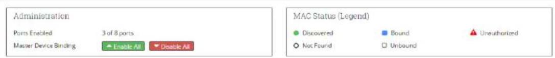
- Administration
• MAC Status (Legend) - Port Status

text_image
razberi Overview PoE Device Binding VLAN HTTPS Network CameraDefense Admin EnglishDevice Binding
text_image
Administration Ports Enabled 3 of 8 ports Master Device Binding Enable All Disable All MAC Status (Legend) ● Discovered ■ Bound ⚠ Unauthorized ○ Not Found □ Unbound
text_image
Port Status Port # Link State Discovered MACs Bound MACs Unauthorized MACs PoE Status Device Bound 1 Up 1 02:00:89:04:33:A5 ▼ Enabled 1 2 Down 02:00:89:04:40:C5 ▼ Enabled 1 3 Down 0 ▼ Enabled 10 4 Down 0 ▼ Enabled 10 5 Down 0 ▼ Enabled 10 6 Up 1 02:00:89:04:40:C5 ▼ Enabled 1 7 Down 0 ▼ Enabled 10 8 Down 0 ▼ Enabled 102.3.1 Device Binding Administration
This pane displays an overview of Device Binding status and allows you to enable or disable MAC level binding for all devices attached to the switch.
Administration
Ports Enabled
Master Device Binding
3 of 8 ports
Enable All
Disable All
• Device Binding Ports Enabled. The number of ports bound to a specific MAC address.
- Master Device Binding makes it easy, with a single button selection, for you to enable or disable all ports for using Device Binding. This is very helpful after initial installation when you have connected all the cameras to the switch.
When you select Enable All, each port with an active device will have its MAC address bound to this port, limiting traffic to this device. Ports without an active device attached will remain disabled.
When you select Disable All, all ports will stop enforcing MAC level device binding. All the values in the Bound MAC address column will be cleared.
2.3.2 MAC Status (Legend)
The legend below explains the various states of Device Binding:
MAC Status (Legend)
Discovered
O Not Found
Bound
□ Unbound
Unauthorized
Discovered (Green Circle). There is active traffic on this port and the MAC address of the device has been discovered. The MAC address discovered is updated whenever a new MAC source address is detected.
Not Found (Open Circle). There is a Bound MAC(s) designated for this port that has not been found meaning they are not transmitting traffic on this port.
Bound (Blue Square). The MAC address shown has been bound to this port and can transmit traffic.
Unbound (Open Square). The MAC address shown is actively transmitting but has not been selected to be bound. Its traffic is blocked.
Unauthorized (Red Alert Triangle). This notifies you that there is authorized MAC found on this port meaning there is a Discovered and Unbound MAC on a port enabled for Device Binding. This condition will generate alerts within CameraDefense (licensed offering) and as part of various VMS Integration solutions.
Device Binding Status features are:
• Port #. The Razberi appliance port number to which the selected device is connected.
- Link State. "Up" indicates that a device is connected to this port; "Down" indicates that no device is connected.
- Discovered MAC Address. This is the number of MAC address' of devices attached to the port and actively sending traffic within the last 90 seconds. The switch automatically detects the MAC address' of any device attached to the port and displays it here. It takes 90 seconds of no traffic from that device for it to be removed from the list.
- Bound MAC Address. This is the only MAC address' the switch will allow to generate or consume traffic on this port. When you enable Device Binding, the "Discovered MACs" will populate in the "Bound MAC Address" column, binding them to this port. If only one MAC is found, the MAC address will be displayed here. If two or more MACs are discovered on this port, the number of MAC bound will be displayed along with a drop-down menu for viewing them and their state.
• PoE Enabled/Disabled. Displays the current PoE Enabled/Disabled status.
- Device Binding Enabled/Disabled. When you enable Device Binding, if there are "Discovered MACs" they will move to the "Bound MACs" column, binding them to this port. Disabling Device Binding clears the "Bound MACs" so you may bind a different MACs on this port.
When you select Enable All, each port with an active device will have its MAC address bound to this port, limiting traffic to this device. Ports without an active device attached will remain disabled.
When you select Disable All, all ports will stop enforcing Device Binding. All the values in the Bound MAC address column will be cleared.
2.3.3 How to Activate Device Binding
Binding to one or more MAC addresses per port is a four-step process:
Step 1 – Attach the camera or authorized device to the port. Power the device via PoE as appropriate to ensure it is active. The Link State of the port must be "Up".
Step 2 – Activate your VMS or camera discovery tool to connect to the camera. Non-camera devices should also be forced to generate traffic through the switch (e.g., Ping command). Devices that generate traffic to the switch will be recognized and the Device Binding UI will provide their MAC addresses in the Discovered MACs column. This column will populate with the number of actively transmitting MAC addresses. The Discovered MACs column list contains the number of MACs seen on that port within the past 90 seconds. Devices that have not transmitted to the switch in 90 seconds will no longer show up on the list. Actively communicating with the cameras (or other devices) will ensure their MAC address is included in the Discovered MAC list.
Step 3 – Enable Device Binding and bind to the Discovered MAC addresses. The Discovered MACs column should now show the number of MACs transmitting per port. Enable Device Binding via the toggle switch. This will bind to up to 8 discovered MACs. The Bound MAC column will now become active. Any more than 8 will display an error message and not allow you to enable Device Binding.
Step 4 – Verify the bound MAC addresses. Once Device Binding is enabled, the Discovered MAC addresses will show up in the Bound MAC column. Select the down arrow to see the states of all discovered MACs. There are three states of MAC addresses within the Bound MAC address list:
- Discovered & Bound: These are MAC addresses that are currently showing up as discovered and are bound using Device Binding. Traffic is coming from these MACs and is being allowed to traverse the switch.
- Discovered & Unbound: These are MAC addresses that are not authorized to transmit and are not bound using Device Binding but they are generating traffic on this port. The MACs will also be show up as a count in the Unauthorized MAC list.
- Not Found & Bound: These are MAC addresses that are bound using Device Binding but are not currently transmitting over the port. These could be devices that have been removed or turned off but whose MAC has been previously bound using Device Binding.
2.3.4 How to Add New Devices / MACs to Device Binding
To add new MAC addresses to the Bound MAC list, disable Device Binding and add the device to the port repeating steps 1 through 4. The new discovered MAC will be bound using Device Binding. Depending on the device added, it may be necessary to connect an application with the device (e.g. VMS or camera discovery tool) to initiate traffic for discovering its MAC address.
2.3.5 How to Remove Devices / MACs from Device Binding
To remove MAC addresses from the Bound MAC list, simply remove the transmitting device (and therefore its MAC) for more than 90 seconds. This will remove the device from the Discovered MAC list. Disable and re-enable Device Binding to bind to those addresses that are discovered, thereby removing non-discovered MACs from the list.
2.3.6 How to Identify and Remove Unauthorized MAC Address'
Should an unauthorized camera or other network device attempt to send traffic over a Device Binding enabled port, it will show up as an Unauthorized MAC and its MAC will be listed in the Bound MAC column's drop down in the Discovered and Unbound state. While it is beyond the scope of this guide to instruction users on how to locate rogue devices, command prompt commands such as "tracert" and open source software such as Wire Shark can be used better understand where devices are connected when more than one network device is between the port and rogue device. Once the device is removed from the port for more than 90 seconds it will no longer show up on the list.
2.3.7 Examples of How Device Binding Works
For examples of how the Device Binding User Interface manages these features, see following image. Here the switch has discovered seven MAC addresses on port two. Six of those addresses are bound using Device Binding and one address appeared after Device Binding was enabled is not authorized. You can see the states of all the MAC addresses by selecting the drop-down arrow (v) within the Bound MAC column for port 2.

Port 4 shows one discovered MAC (see image below). When one and only one MAC is bound, it will show up in the Bound MACs column. You can always select the drop-down arrow within the Bound MAC column to confirm a MAC's state.

text_image
4 Up 1 00:18:85:07:AE:06 EnabledThe image shows the states of the seven discovered MACs by selecting the down arrow in the Bound MAC column. Note how the MAC at the end of the list is Discovered and Unbound – meaning it is the “Unauthorized MAC” displayed in the Unauthorized MACs list.
When you disable Device Binding, the list of Bound MACs is cleared and again ready to be bound from the discovered MACs list. Users may add or delete MACs by physically adding or removing devices showing up in the Discovered MAC column as previously described.
2.4 VLAN Page
ServerSwitchIQ managers should consider creating a separate VLAN for endpoints other than Video Cameras. For example, a second VLAN could be created for a Voice of IP phone, printers, or computers sharing the same ServerSwitchIQ switch – while the default VLAN (VLAN 1) would be used strictly by cameras and the VMS software. In this way, traffic from a separate network with a different purpose is prevented from mingling with or allowing access to security equipment or accessing security traffic and vice versa. The following VLAN page shows how the ServerSwitchIQ appliance could be configured to satisfy this use case.

text_image
razberi Technologies Overview PoE VLAN HTTPS Network CameraDefense Admin English VLAN Enable Trunk Mode VLAN ID VLAN Name 1 2 3 4 5 6 7 8 9 10 11 12 13 14 15 16 17 18 19 20 21 22 23 24 U1 CPU DHCP 1 default ✗ ✗ ✗ ✗ ✗ ✓ ✓ ✓ ✓ ✓ ✓ ✓ ✓ ✓ ✓ ✓ ✓ ✓ ✓ ✓ ✓ ✓ ✓ ✓ ✓ ✓ ✓ ✓ ✓ ✓ ✓ ✓ ✓ ✓ ✓ ✓ ✓ ✓ ✓ ✓ ✓ ✓ ✓ ✓ ✓ ✓ ✓ ✓ ✓ ✓ ✓ ✓ ✓ ✓ ✓ ✓ ✓ ✓ ✓ ✓ ✓ ✓ ✓ ✓ ✓ ✓ ✓ ✓ ✓ ✓ ✓ ✓ ✓ ✓ ✓ ✓ ✓ ✓ ✓ ✓ ✓ ✓ ✓ ✓ ✓ ✓ ✓ ✓ ✓ ✓ ✓ ✓ ✓ ✓ ✓ ✓ ✓ ✓ ✓ ✓ ✓ ✓ ✓ ✓ ✓✓✓✓✓✓✓✓✓✓✓✓✓✓✓✓✓✓✓✓✓✓✓✓✓✓✓✓✓✓✓✓✓✓✓✓✓✓✓✓✓✓✓✓✓✓✓✓✓✓✓✓✓✓✓✓✓✓✓✓✓✓✓✓✓✓✓✓✓✓✓✓✓✓✓✓✓✓✓✓✓✓✓✓✓✓✓✓✓✓✓✓✓✓✓✓✓✓✓✓✓√ 10 IP Telephony ✓ ✓ ✓ ✓ ✓ ✓ ✗ ✗ ✗ ✗ ✗ ✗ ✗ ✗ ✗ ✗ ✗ ✗ ✗ ✗ ✗ ✗ ✗ ✗ ✗ ✗ ✗ ✗ ✗ ✗ ✗ ✗ ✗ ✗ ✗ ✗ ✗ ✗ ✗ ✗ ✗ ✗ ✗ ✗ ✗ ✗ ✗ ✗ ✗ ✗ ✗ ✗ ✗ ✗ ✗ ✗ ✘ 20 Corporate LAN - PC ✓ ✓ ✓ ✓ ✓ ✓ ✗ ✗ ✗ ✗ ✗ ✗ ✗ ✗ ✗ ✗ ✗ ✗ ✗ ✗ ✗ ✗ ✗ ✗ ✗ ✗ ✗ ✗ ✗ ✗ ✗ ✗ ✗ ✗ ✗ ✗ ✗ ✗ × ✓ Included in VLAN ☒ Excluded from VLAN √ Feature Enabled ☒ Feature Disabled SaveCreating Tagged VLAN Example. Your ServerSwitchIQ switch (and every EndpointDefender) has the ability consume and provide IEEE 802.1Q compliant tagged VLANs. In the image above, we have a ServerSwitchIQ configured for three tagged VLANS (1, 10, 20) - VLAN 1 the default camera and administration VLAN; VLAN 10 an IP Telephony VLAN for providing VoIP traffic to ports 1-5; and, VLAN 20 the corporate VLAN for connecting compute nodes (laptops, servers, etc.) also on ports 1 – 5. VLAN Setup follows four steps.
First create two additional tagged VLANS 10 and 20 giving them a unique recognizable name.
Second designate U1 as capable of consuming an inbound trunk and ports 1 – 5 as providing trunks to IP Telephony devices. That is done by selecting Enable Trunk Mode for those ports.
Third, move ports 1 – 5 from the default camera VLAN adding them to both the IP Telephony and Corporate VLANS (10, 20). Trunked ports can share membership with multiple tagged VLANS, while device ports that are not enabled as trunks can only be a member of one tagged VLAN.
Forth, ensure U1 is included in VLANS 1, 10, and 20. Complete the configuration by selecting Save.
In this configuration, you have created three distinct tagged VLANS for three different data traffic purposes. Ports 1 – 5 will connect to IP phones capable of consuming tagged VLANs 10 and 20 for providing both VoIP and PC data. Laptops and similar devices could connect the data port of the IP phone. This is a common practice with Cisco, Polycom, and other IP phones. Device ports 6-24 contain cameras and isolate camera traffic from the other devices and networks. The CPU selected means the default VLAN could be connected a Video Management System running on the ServerSwitchIQ server (the CPU).
What follows are general instruction on how to add, delete, and update a VLAN.
Adding a VLAN. Users can add a new VLAN by selecting the Add VLAN button as shown in the image above. Immediately, a new row filled with red "X"s is displayed for all possible members, allowing you to select any port, uplink, or CPU connection to be added to the new VLAN.
Edit the VLAN ID. It is important to provide a VLAN ID, especially for tagged VLANs. The allows the switch to consume or provide tagged VLANs matching that ID.
Describing a VLAN. Users can provide each VLAN a unique, human readable name. For example, "Building 1202 - 3^rd Floor Cameras" might be helpful for identifying the function and location of endpoints. As shown in the image, users simply select the description field, make any edits.
Updating the Membership of a VLAN. As mentioned in the example, trunk ports should be members of more than one VLAN. Device ports can only be a member of one VLAN. Simply select the port (column) and VLAN (row) that you want update.
Deleting a VLAN. Users can delete a VLAN by selecting the Delete Icon at the end of the VLAN row. When you delete a VLAN, any members of that VLAN are immediately returned to the membership of VLAN 1 the default VLAN if not members of other VLANs.
Enabling the Switch's DHPC Server within a VLAN. Only VLAN 1 (the default VLAN) can employ the DHCP Server of the Razberi switch. If other VLANS require DHCP address assignment, then an external DHCP server must be provided and accessible within the networks of VLANs 2 or greater.
DHCP. The switch's DHCP server is currently only available on VLAN 1 (default). It will show as enabled once the switch's DHCP server is activated in the Network page of the switch of the ServerSwitchIQ.
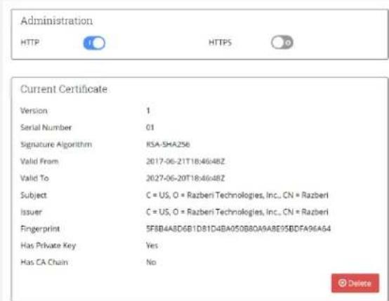
2.5 HTTPS
Users desiring transport layer encryption (TLS) of data being passed from the browser to the switch can implement HTTPS. This is particularly important when resetting the switch's password to prevent the potential of someone obtaining the switch's password from unencrypted traffic. Below is the screen used to manage HTTPS.

text_image
razberi Technologies Overview PoE VLAN HTTPS Network CameraDefense Admin EnglishHTTPS
text_image
Administration HTTP HTTPS Current Certificate Version 1 Serial Number 01 Signature Algorithm RSA-SHA256 Valid From 2017-06-21T18:46:48Z Valid To 2027-06-20T18:46:48Z Subject C = US, O = Razberi Technologies, Inc., CN = Razberi Issuer C = US, O = Razberi Technologies, Inc., CN = Razberi Fingerprint 5FBB4A8D6B1D81D4BA050B8DA6A8E95B0FA96A64 Has Private Key Yes Has CA Chain No Delete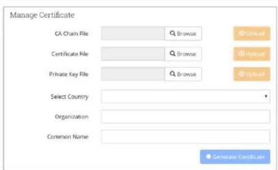
text_image
Manage Certificate CA Chain File Browse Certificate File Browse Private Key File Browse Select Country Organization Common Name Generate Certificate2.5.1 HTTPS Administration
ServerSwitchIQ supports three modes for implementing HTTPS using both self-signed and CA certificates. These modes are: 1) HTTP only, 2) HTTP or HTTPS (based on the URL selected), or 3) HTTPS Only. These modes are activated using the toggles as shown in the HTTPS Administration pane. For any of these modes to take affect after a change, the user must reboot the switch.
Note that the "HTTPS" enabled/disable toggle will not be selectable until you either 1) generate a self-signed certificate, or 2) you upload matching bundle, certificate, and key files. The switch checks to ensure these are valid, matching files before allowing you to activate HTTPS.
When transitioning from "HTTPS" to "HTTP only" mode, the browser cache must be cleared one time - typically requiring you to delete the browser history. A simple "CNTL + F5" may not work. Otherwise, the browser will timeout trying to connect via HTTPS.
2.5.2 Manage Certificate
ServerSwitchIQ allows users to use Certificate Authority (CA) generates bundle files, certificate files, and private keys and, enables the generation of random self-signed certificates.
To use a Third Party CA, one must upload the CA Bundle - a file that contains well known root CA certificates. Next, you will upload your certificate provided by the CA. Both files must end in either a “.crt” or “.cer” extension to be uploaded. Finally, upload the private key whose filename must end in a “.key” extension to be uploaded. Once all three of these files have been uploaded, you must reboot the switch for the third-party CA certificate to take effect.
To use a self-signed certificate simply select the country of the appliance, your organizations' name, and a "Common Name". Selecting the correct "Common Name" is important only if you are using a Domain Name Server (DNS) to resolve the name to the switch IP address. If you use the Common Name with your DNS resolution, it will prevent your browser from getting a warning that server name and certificate do not match. However, with self-signed certificates, you will still get a warning that this certificate is not a trusted signing authority. This warning typically only occurs the first time you use the browser for that site.
Once all three of these fields are complete the "Generate Certificate" button will become active. Once you select "Generate Certificate" a self-signed certificate will be created and the switch will automatically reboot. Once the reboot is complete, the switch now has valid self-signed certificate and the HTTPS mode can be activated.
2.5.3 Current Certificate Information
The information pertinent to the currently installed certificate (Third-Party or Self-Signed) is displayed here for users to review and verify. To update certificates or any of the information in this pane once new certificates or keys are provided one must reboot the switch. Once rebooted, the switch will display the most current certificate information.
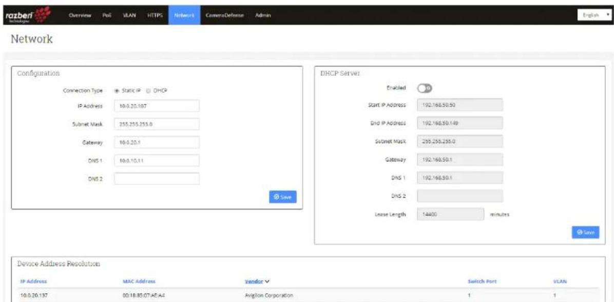
2.6 Network Page
The network page allows you to configure the IP address of the switch and to manage the built-in DHCP server controlling the assignment of IP addresses of cameras or other devices attached to the switch's ports.
The Network screen contains three panes:
- Switch Configuration
- Switch DHCP Server
• Device Address Resolution
text_image
ratberi Network Overview Poll VLAN HTTPS Network CameraDefense Admin English Network Configuration Connection Type Static IP DHCP IP Address 10.0.20.107 Subnet Mask 255,255,255.0 Gateway 10.0.20.1 DNS 1 10.0.10.11 DNS 2 DHCP Server Enabled 36 Start IP Address 192,168,50.50 End IP Address 192,168,50.149 Subnet Mask 255,255,255.0 Gateway 192,168,50.1 DNS 1 192,168,50.1 DNS 2 Lease Length 14400 minutes Device Address Resolution IP Address MAC Address Vendor Switch Port VLAN 10.0.20.137 00:18:85:07:EA:A4 Avigilon Corporation 1 12.6.1 Switch Configuration
This pane allows you to manage the IP assignment of the switch, its subnet mask, gateway, and DNS.

text_image
Configuration Connection Type Static IP DHCP IP Address 192.168.50.1 Subnet Mask 255.255.255.0 Gateway DNS 1 DNS 2 SaveThe factory default setting is a Static IP connection type with an address of 192.168.50.1 and a subnet mask of 255.255.255.0.
You can enter a different address through this pane; however, for most security camera implementations, we recommend the use of the default settings. The reason is that this network will normally be isolated from the corporate LAN and will only be used for managing and collecting camera and related security application data by the video management software (VMS) residing on the server.
If an installation requires that other applications, not residing on the Razberi server, be able to access devices on the switch, then that traffic must pass through a physical connection to the U1 port. However, in most instances this is undesirable, and not recommended, since it would introduce traffic from cameras to the corporate LAN.
If direct access to devices on the switch from external applications is required, then you should set the Gateway, DNS 1, and DNS 2 to allow traffic to pass from the switch to other subnets and to resolve domain names to IP addresses.
Features of this pane are:
- Connection Type. The default setting is Static IP. If you select the DHCP option, an external DHCP server that is accessible via the U1 connection will dynamically assign the switch's IP address, DNS, and Gateway.
- IP Address. The IP address of the U1 switch connection. It can be used by a web browser with proper authentication to access the switch's web-based interface.
- Subnet Mask. The subnet mask of the U1 switch connection.
• Gateway. The gateway for accessing the U1 switch connection.
• DNS 1. The primary domain name server used by the switch.
• DNS 2. An alternate domain name server used by the switch. - Save. Saves the changes made in any of the network settings. For these changes to take effect, you must reboot the switch. A reminder displays at the top of the page after your select "Save." as shown below:

text_image
razberi Technologies Overview PoE LocBeri Network Admin English Successfully set the network configuration. You need to restart the device for the changes to take effect. Reboot now LaterShould you decide to reboot the device later, another message in RED will persist across the top of the UI reminding you that your changes have not yet taken effect, as shown below:

text_image
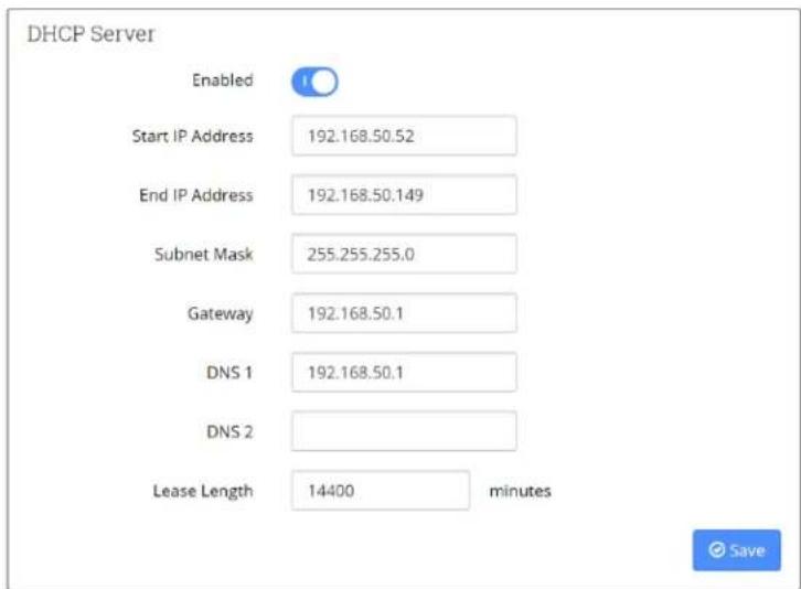
razberi™ technologics Overview PoE LocBeri Network Admin English You need to restart this device for the changes to take effect. Reboot now2.6.2 DHCP Server
From this pane, you can configure the switch to use its internal DHCP server for assigning IP addresses to attached devices. You can also set the dynamic IP address lease length for renewal with a minimum setting of 60 minutes.
In camera security use cases—where only the VMS on the Razberi server is accessing them and there is no external network connection to the switch via the U1 connection—there is no need to set the Gateway, DNS 1 or DNS2.
However, when using the U1 connection for allowing devices to access or be accessed by external applications you must define the gateway and DNS addresses.
Finally, the Razberi server's Intel I211 network connection to the switch must also be set to DHCP for it to receive an IP address on the switch.
WARNING: If the switch's DHCP is enabled and the Razberi is connected to an external network via the U1 network connector, no other DHCP hosts can be in use on the external network, otherwise there will be IP address conflicts. The switch's DHCP host should not be used when other external DHCP hosts are in use and accessible to the switch.
To help prevent you from accidentally enabling the switch's DHCP server (as outlined in the warning message above), when an external DHCP server is connected to one of the switch's ports or U1, the switch will check for the presence of an external DHCP server after rebooting, and will prevent you from enabling DHCP. Therefore, if you are trying to enable the switch's DHCP server and you notice that it will not enable after a reboot, it is the switch preventing network conflicts by automatically disabling the DHCP server.
text_image
DHCP Server Enabled Start IP Address 192.168.50.52 End IP Address 192.168.50.149 Subnet Mask 255.255.255.0 Gateway 192.168.50.1 DNS 1 192.168.50.1 DNS 2 Lease Length 14400 minutesThe features of this pane are:
- Status Enable/Disable. The default setting is to disable the switch's DHCP server. This means that you must manually assign IP addresses to cameras or use an external DHCP server accessible via the U1 network connection for IP assignment.
- Start/End IP Addresses. When DHCP is enabled, you can choose a Start and End IP address range for assignment of attached devices.
- Subnet Mask. The subnet mask of the U1 switch connection.
• Gateway. The gateway that could be used to access the U1 switch connection.
• DNS 1. The primary domain name server used by the switch.
• DNS 2. An alternate domain name server used by the switch. - Lease Length. The suggested length of time in minutes that the DHCP server will use for potentially reassigning its pool of dynamic IP addresses. A minimum of 60 minutes is enforced.
- Save. Saves the changes made in any of the network settings. For these changes to take effect, you must reboot the switch. A reminder displays at the top of the page after you select "Save," as shown below:

text_image
razberi Technologics Overview PoE LocBeri Network Admin English Successfully set the network configuration. You need to restart the device for the changes to take effect. Reboot now LaterShould you decide to reboot the device later, another message in RED will persist across the top of the UI reminding you that your changes have not yet taken effect.

text_image
razberi™ Technologies Overview PoE LocBeri Network Admin English You need to restart this device for the changes to take effect. Reboot now2.6.3 Device Address Resolution
This table displays IP traffic that is passing through the switch. This is dynamically updated as new traffic appears and old traffic fails to show up. There is 5-minute retention time on unique source and destination traffic. Each column is sortable. These columns are defined as follows:
IP address. The source IP address of traffic
MAC address. The MAC address of the traffic.
Vendor. A description of the vendor or owner of that MAC address.
Switch Port. This shows which port the traffic was observed coming from. There are generally three categories. U1 – the gigabit link on the outside of the ServerSwitchIQ; Internal – The internal Network Interface Connection on the server, and the switch port the traffic was
observer coming from. For example, traffic coming from a camera on Switch Port 1 would list the switch port, IP of the camera, MAC of the Camera and vendor or owner of that MAC address.
VLAN – The VLAN ID that the traffic was observed on. This can vary over time if traffic can exist on multiple VLANs.
2.7 CameraDefense™ Page
2.7.1 Introduction
To protect your surveillance systems and prevent infiltration into your network and critical data, Razberi provides CameraDefense™. CameraDefense automates camera hardening (and other connected devices) against cyber threats in five ways. First, it blocks unauthorized devices from using razberi ethernet ports, next it secures access to the cameras by restricting traffic to a whitelisted IP network or addresses and blocks camera traffic to the public internet. Third, it protects against cyberattacks by preventing unnecessary and potentially dangerous services with a next generation firewall. Forth, it inspects basic and digest authentication requests and alerts on common or default passwords when used. Finally, it integrates with various Video Management Systems for alerting security staff of security violations and possible cyberattacks to prevent surveillance system infiltration. You can use your existing VMS management consoles to receive real-time alarms (currently supporting Milestone Integration).
2.7.2 CameraDefense Included in Select Models
CameraDefense is a feature provided on some models of the ServerSwitchIQ. For those units that do not have CameraDefense, the tab will be "grayed-out" with a Device Binding Tab for allowing MAC Address binding.
2.7.3 CameraDefense Setup Wizard
CameraDefense includes an intuitive Setup Wizard that must be run the first time you start CameraDefense. The Setup Wizard helps ensure you follow the right steps for properly implementing best practices against cyberattacks. Most users should be able to complete setup of CameraDefense in less than 4 minutes if they do the following prior to running
CameraDefense:
- Cameras and all other devices are connected to the switch and generating traffic.
• The VMS is configured and running, and - You have the addresses of any networks you want to whitelist from the camera ports and U1.
Now, we'll go through each step of the CameraDefense setup wizard.
INTRODUCTION:
The introduction asks you that the previously mentioned prerequisites are complete prior to starting CameraDefense.
CameraDefense: Setup
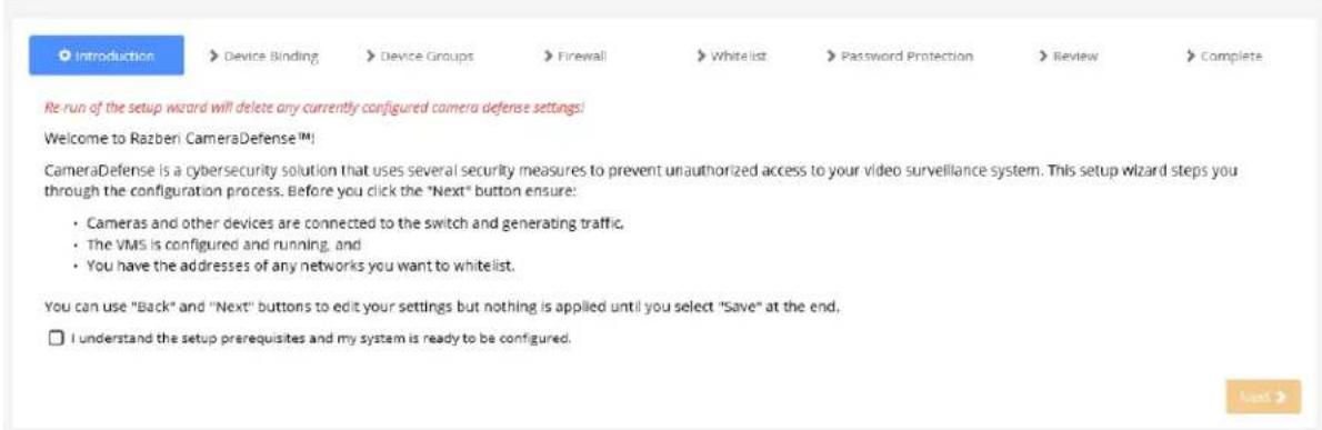
text_image
Introduction Device Binding Device Groups Firewall Whitelist Password Protection Review Complete Re-run of the setup wizard will delete any currently configured camera defense settings! Welcome to Razben! CameraDefense™! CameraDefense is a cybersecurity solution that uses several security measures to prevent unauthorized access to your video surveillance system. This setup wizard steps you through the configuration process. Before you click the "Next" button ensure: • Cameras and other devices are connected to the switch and generating traffic. • The VMS is configured and running, and • You have the addresses of any networks you want to whitelist. You can use "Back" and "Next" buttons to edit your settings but nothing is applied until you select "Save" at the end, I understand the setup prerequisites and my system is ready to be configured.After you have connected all devices to your razberi switch, have the VMS and any other access control or related device application software running, and you have a list of any IP networks or addresses you want to whitelist - select the prerequisites box to activate the "Next" button. Note that the once you complete a step in the Setup Wizard, you'll be able to go back to previous steps using the "Back" button or by selecting the highlighted blue sub-menu tabs. If you select any of the main menu tabs or refresh the page within the setup wizard, you will have to start over at the beginning.
DEVICE BINDING:
Device Binding secures traffic to known MAC addresses and disables unused ports to physically secure your razberi. Device Binding identifies any actively transmitting devices on each port (and can handle up to 8 MACs per port) and shows their MAC address and the name of its Organizationally Unique Identifier (OUI). The Result column tells you what changes Device Binding will make to your razberi to improve your security. On the right, you can select or deselect ports you want Device Binding to implement. For example, if you deselect port 1, then it will not bind the MAC address of the device connected to that port.
Below we have ports 1 and 6 with cameras. These ports will be bound to the MAC addresses found. Port 2 does not have a device and it is already disabled, therefore there are no changes required for that port. That is why the results for Port 2 is blank. Ports 3, 4, and 5 do not have devices connected but are active ports so the result column shows those ports will be disabled. In summary, in the result column “Bound” means that the MAC addresses shown for that port are the only MAC addresses allowed to originate or receive traffic upon saving the results at the end of the setup wizard process. “Disabled” means that port will be disabled and not allow any traffic for that port.
√ Introduction
Device Binding
Device Groups
Firewall
Whitelist
Password Protection
Review
Complete
Device binding limits traffic to the MAC addresses found on active ports and disables inactive ports. Before you hit "Next":
- Select the ports you wish to bind to devices or disable if inactive.
• Devices must be generating traffic to be bound to that port. - Ports without devices (Link State Down) will be disabled to prevent unauthorized access.
| ✓ Port # | Port Enabled | Link State | Devices | Result |
| ✓ 1 | Enabled | Up | Avigilon Corporation - 00:18:85:07:AE:fB | Bound |
| ✓ 2 | Disabled | Down | ||
| ✓ 3 | Enabled | Down | Disabled | |
| ✓ 4 | Enabled | Down | Disabled | |
| ✓ 5 | Enabled | Down | Disabled | |
| ✓ 6 | Enabled | Up | Avigilon Corporation - 00:18:85:07:AF:00 | Bound |
If a device is connected to a port but it is not generating any traffic, within the "Devices" column you will see a message that the connected device is not generating traffic and cannot be bound. To correct this, ensure the camera (or other device) is connected to application software that requires the device to generate traffic (VMS, Access Control Software, etc.). It can take a few minutes for the switch to discover new traffic. Once you are generating traffic for that port, immediately return to the Introduction page by selecting "Back" then hitting "Next" to refresh the results.
DEVICE GROUPS:
The next step allows you to assign uniform security policies to similar devices. By default, CameraDefense creates a Cameras device group for all active ports. Should you need to assign different Firewall or Whitelist settings to different devices, create a new device group by selecting the "Add" button. A green check mark means the device on the part is included in that group, a red "X" means that this active port is not assigned to that device group, and a gray X means that port is disabled and cannot be added to any device group.
To follow best practices and avoid warnings, ensure every active port is assigned to a device group. You can use the "Select All" feature if needed to ensure you have assigned all your units that group, otherwise by default all active ports are assigned to the "Cameras" device group. Hit "Next" to proceed to the next step.
√ introduction
√ Device Binding
Device Groups
Firewall
Whiteist
Password Protection
Review
Complete
A device group is a set of similar devices assigned the same security policies. By default, all active ports are assigned to the "Cameras" device group. If cameras are the only devices connected to the SSIQ then hit "Next", otherwise:
- Create a new device group for the non-camera devices giving it a unique name.
- Add the ports of the non-camera devices to the new device group.
- Review the port assignments by device type since devices can only be a member of one group.
Firewall and Whitelist features are disabled for device groups without any port assignments.
| Group Name | Select All | 1 | 2 | 3 | 4 | 5 | 6 | 7 | 8 | 9 | 10 | 11 | 12 | 13 | 14 | 15 | 16 | 17 | 18 | 19 | 20 | 21 | 22 | 23 | 24 | + Add |
| Cameras | √ | √ | ✕ | ✕ | ✕ | ✕ | ✕ | ✕ | ✕ | ✕ | ✕ | ✕ | ✕ | ✕ | ✕ | ✕ | ✕ | ✕ | ✕ | ✕ | ✕ | ✕ | ✕ | ✕ | ✕ |
√ Included in device group
✗ Excluded from device group
× Port disabled
B
Note
ACTIVATING THE EMBEDDED FIREWALL:
CameraDefense includes an embedded firewall that can be customized by device group. This feature restricts traffic to only specific service ports by protocol (UDP or TCP) for a specific camera group. By default, device groups are only enabled to support the most common video services of HTTP, HTTPS, and RTSP.
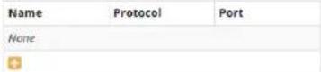
If needed, you may quickly enable common services such as Bonjour Telnet, SSH, FTP, etc. by selecting them from the Allowed Network Services section. You can also add custom services that need to be operational within the "Additional Custom Service" pane. Select the [ + ] add button, provide a unique name, protocol and port or port ranges. For example, Acme Camera Services, UDP, 5000-5500. Up to 4 UDP and 4 TCP custom services per device group can be created. NOTE: If you select Disable Firewall, no service restrictions will be put in place for devices in that device group and this will raise a warning in the CameraDefense Dashboard.
√ Introduction
√ Device Binding
√ Device Groups
Firewall
Whitelist
Password Protection
Review
Complete
Use the firewall feature to limit traffic to video services and to disable discovery services. For each device group:
- Select HTTP, HTTPS, and RTSP services for device groups with cameras.
- Disable discovery services to prevent cyber attackers from finding devices.
- Allow additional services as needed providing the name, protocol, and port.
Device Group: Cameras [ports 2.3.6.10]
□ Disable Firewall
Allowed Video Services:

Allowed Network Services:

Allowed Custom Services:
Most users and use cases will be served by using the default selection of HTTP, HTTPS, and RTSP for each device group. Once you have completed your firewall settings, select "Next" to move to the next step for enabling Internet Protection or Special Whitelists.
WHITELIST:
A whitelist restricts IP traffic for a specific device group. By default, each device group will be assigned Internet Protection which prevents cameras from communicating over routable IP addresses (the Internet). An even more restrictive approach is to provide a specific network mask using the Whitelist. Shown separately is Uplink 1 (U1). If U1 is not disabled, you can restrict traffic on it to a known network. This feature prevents unauthorized corporate traffic on U1 from reaching your Razberi's switch. Shown below, the Camera device group is preventing internet access and U1 is restricting traffic to the 10.0.10.X network.
√ Introduction
√ Device Binding
√ Device Groups
√ Firewall
Whirlist
Password Protection
Review
Complete
A whitelist limits traffic to specified networks by device group. The default option of Internet Protection prevents devices from communicating over routable networks such as the Internet. For each device group:
- Use Internet Protection to prevent devices from reaching routable networks, otherwise
- Specify the allowed networks using sub-masks and/or individual IP addresses.
- Enable alerts for devices that attempt to communicate outside of the whitelist.
Limit traffic on Uplink 1 (U1) to specific networks and/or IP addresses in the same way as device groups.
Device Group: Cameras (ports: 1,23)
Internet Protection
○ Whitelist
○ Disabled
Enable Alerts
Uplink 1 (U1)
● Whitelist
○ Disabled
Allowed Addresses:
IP Address or Mask
10.0.10.0/24


Whitelist alerts are raised whenever a device attempts to communicate outside the whitelist. Therefore, if a camera attempts to reach the internet an alert will be raised. Once you are done, hit next to proceed to Password Protection.
PASSWORD PROTECTION:
Password Protection involves deep packet inspection of unencrypted basic and digest authentication requests it devices on LAN ports. If a user or application attempts to authenticate using default or common passwords found on the NIST Bad Password list an alert will be raised. Most cameras and access control devices use these forms of authentication allowing you to monitor password selection regardless of the vendor or model of the device. By default, password protection is enabled.
√ Introduction
√ Device Binding
√ Device Groups
√ Firewall
√ Whitelist
Password Protection
Review
Complete
This feature monitors your devices to ensure they are not using default or common passwords found on the NIST Bad Password List. By default, Password Protection is enabled.
Enable Password Protection

Select next to review all your CameraDefense setting prior to saving them.
REVIEW:
A helpful feature is the review page. This allows you to confirm all CameraDefense settings and print them (or save them as a PDF using your browser) prior to saving and committing the changes.
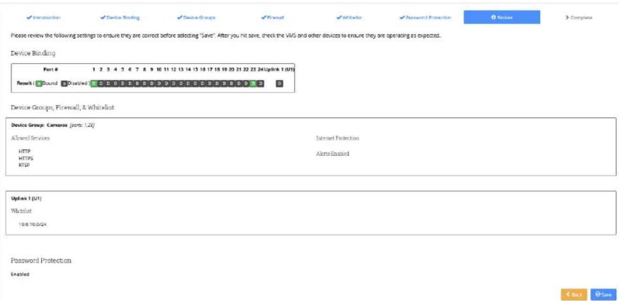
text_image
Introduction Device Binding Device Groups Result Withdraw Password Protection Finish Complete Please review the following settings to ensure they are correct before selecting "Save". After you hit save, check the VMS and other devices to ensure they are operating as expected. Device Binding Port # 1 2 3 4 5 6 7 8 9 10 11 12 13 14 15 16 17 18 19 20 21 22 23 24 UpLink 1 (UT) Result ( Bound Disabled ) C D E F G D H G I D E D D E D B D B D S D Device Groups, Firewall, & Whitelist Device Group: Camera (port: 1.29) Allowed Services Internet Protection HTTP Alerts Enabled HTTPS RTSP Uplink 1 (UT) Whitelist 19.0.10.0/24 Password Protection EnabledAll key settings are displayed for your review. If you see something that is wrong, you can jump directly to that section by selecting it in the blue submenu. Note that doing so means you must progress through some of the setup screens again, but if no changes are needed there, simply hit next to return to the Review page.
Once you hit save, the settings for CameraDefense will be committed to the Razberi appliance. After saving double check that there are no disruptions of video or lost connectivity of devices. The firewall feature is powerful. If you find unintended disruptions in traffic, go to the Dashboard to add services or correct / add additional network whitelists that could be causing the problem. You can temporarily disable the firewall setting for the device groups to verify the
firewall is blocking your traffic. In practice, if you have followed the defaults settings you should not have issues for typical VMS / Camera configurations.
2.7.3 CameraDefense Dashboard
Shown below we have the typical dashboard most users will find after completing the Setup Wizard:
CameraDefense: Dashboard
Re-run Setup
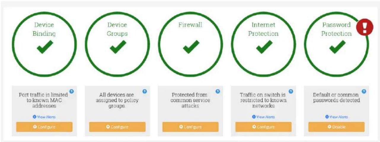
text_image
Device Binding Device Groups Firewall Internet Protection Password Protection Port traffic is limited to known MAC addresses View Alerts Configure All devices are assigned to policy groups Configure Protected from common service attacks Configure Traffic on switch is restricted to known networks View Alerts Configure Default or common passwords detected View Alerts DisableIn the example above, all recommended best practices have been successfully implemented. We also see there is one alert for Password Protection where a device is using a default or common password. Selecting the "View Alerts" link we see:
CameraDefense: Alerts

text_image
System alert interface showing timestamp, alert type, and description of a camera password with MAC address 00:18:85:07:AP:00.The camera on port 1 has a default password and this is generating an alert. This is a state-based alert meaning you cannot clear it until you change that camera's password to something that isn't the default. If you changed it to "123456" a common password, that would generate a common password alert.
CHANGING DEVICE CONFIGURATIONS:
For most changes, it is recommended that you select the Re-run Setup link on the top right of the Dashboard. Doing so clears the previous CameraDefense settings and starts over fresh. This helps you follow the recommended process and best practices. For more experienced users or
setups with custom firewall and whitelist settings you can jump directly to the configuration of any CameraDefense feature. After making your change, you must select "Save" to commit the change. An example is directly going to the Firewall or Whitelist configuration settings when you want to disable the firewall or whitelist for a device group as part of a test. Another example is when you want to review details involving a multiple MAC device binding configuration.
MEANINGS OF THE RED, YELLOW, GREEN AND ALERT DASHBOARD STATUS:
What follows is a brief description of the alert status' and what triggers them. These descriptions can also be found when selecting the information icon within a specific Dashboard feature.
Device Binding
- Green: All found MACs are bound. Traffic is limited to this MAC(s) per port.
- Yellow: One in a list of MACS are not bound. Also caused when one or more ports without an active device connected are enabled.
- Red: None of the devices attached are bound.
- Alert: A device whose MAC does not match the bound MAC has been found. This is an unauthorized MAC alert. The offending device will need to be removed or its MAC(s) bound to clear this alert.
Device Groups
- Green: One or more devices are assigned to one or more device groups. Some ports may not be assigned to a device group.
- Yellow: There are device groups without port assignments.
- Red: None of the devices are assigned to a device group.
Firewall
- Green: Only "Allowed Services" are selected.
- Yellow: Discovery Services are enabled. Also, one of two or more firewalls are disabled.
- Red: Firewall is disabled for all device groups.
Whitelist / Internet Protection
- Green: All devices groups have Internet Protection or Whitelists or a mix of Internet Protection and Whitelists.
- Yellow: One device group has a whitelist while another is disabled.
• Red Status: No whitelist (or Internet Protection) is enabled for any device group. - Internet Protection Displayed: Internet protection is the only option selected all device groups. protection
- Whitelist Displayed: If one whitelist is selected for any device group.
- Alerts: There is a whitelist violation from a device on a LAN port. Clearing history removes it if no more alerts are found.
Password Protection:
- Green Status: Password protection is enabled.
• Red Status: Password protection is disabled.
- Alerts: A device has a common or default password. The password of the offending device will need to be corrected to remove this alert.
2.8 Admin Page
From this page you can perform basic administrative functions. The Admin screen contains four operational panes:
- Security
- Maintenance
- Settings
- Firmware
- Firmware
- License
- Razberi Monitor
razberi

Overview
PoE
VLAN
HTTPS
Network
CameraDefense
Admin
Admin
Security
Settings
Firmware
Maintenance
a License
Razberi Monitor
Security
Username
admin
Password

New Password

Confirm New Password


2.8.1 Security
This pane allows you to set the password for the switch administrator. The appliance's switch only has one user named "admin" whose factory default password is "system". To change the administrator's password, you must enter the current password, the new password, and repeat the new password, then click Save.
If users forget their current password, they must contact the server administrator (if they do not have server administrator privileges) for resetting the server to its factory default of username: "admin" with password: "system" using the Setup Wizard application discussed within this guide.
2.8.2 Maintenance
You will use this pane to reset the switch to its factory default, to reboot after making network settings or other significant configuration changes, and when backing up or restoring the switch's configuration settings to a file.
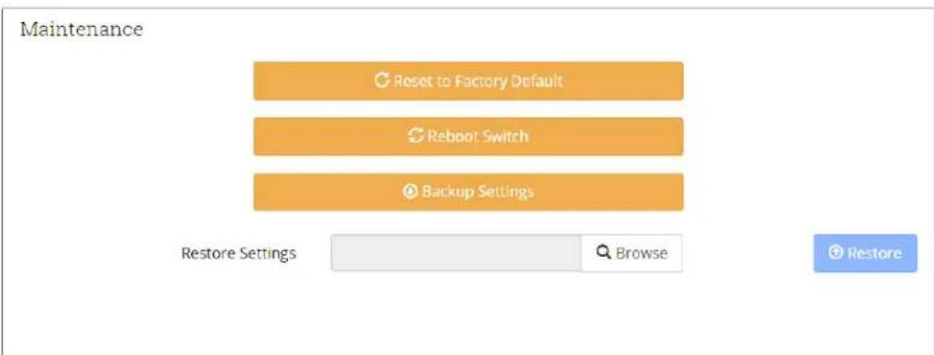
text_image
Maintenance Reset to Factory Default Reboot Switch Backup Settings Restore Settings Browse RestoreYou must reboot the switch to commit changes to the switch's IP address assignments or to enable/disable changes in DHCP/Static IP assignment behavior.
For example, if you change the switch's IP address, this will not take effect until the switch is rebooted. Rebooting the switch causes all devices to temporarily lose connectivity with the switch (including PoE).
When you select "Reset to Factory Default" or "Reboot Switch," you will see an alert message (below) that requires your confirmation to be sure you want to take this action and to help prevent an accidental reset/change in the switch.

text_image
razberi Technologix Overview PoE LocBeri Network Admin English Rebooting Switch. Are you sure? No YesWhen you select the "Backup Settings" button, a backup file will be stored in the Downloads folder of your browser. The name of the .gz tar file created includes the Model and Serial number of the unit to help accurately identify which Razberi the settings represent. It is recommended that once you complete your setup and installation save the configuration off the unit for future reference and replacement of units. All configuration related settings except username and password will be saved in this file.
To restore the settings, simply select the "Restore" button and choose the correct .gz tar file. Double check the file name (Model and Serial) and file extension (.gz) shown to ensure you have selected the correct file and file type to avoid any downtime of your unit. Once the settings are restored, the switch will automatically reboot to accept all restored changes. Note that the username and password is not included in the restore file. Users can access the switch UI using the same credentials prior to the restore event.
2.8.3 Settings
You can view and configure the switch's device name, where it is located in your system, its NTP server, view its current time, and if you want it to become an NTP proxy for endpoints connected to it.
Provide a custom device name and location for use in Razberi Monitor and MonitorCloud by updating and saving these field.
Having the correct local time for the switch is important when time stamping cybersecurity events and viewing the audit logs collected by Razberi Monitor. The switch will by default adopt its time from the server's time (via UDP port 124 of the server) unless you have a reason for not doing so. In that case, you can specify an external NTP server that uplink 1 (U1) will have access to. Simply enter the external NTP server address and save the configuration.
The NTP Proxy feature allows devices connected to the switch to use the switch address assigned on the switch's network page as an NTP proxy. Its time is derived from the operating system of the ServerSwitchIQ server. When selected, cameras or other endpoints needing accurate time simply point to the IP address assigned to the switch for obtaining the same time as the server. The Razberi Monitor agent service must be running on the server for the NTP proxy feature to work.
Settings
Device Name
ServerSwitchIQ 17
Device Location
10.0.20.112 / Building 12 / Room 1221 / Rack B7 / RU 38
Current Time
05/12/2018 11:57:24 AM
NTP Server
10.0.20.62:124
Enable NTP Proxy

Save
2.8.4 Firmware
This pane is used to change the firmware of the switch. It shows the current installed firmware version and allows you to browse on the host device of the browser to select the new firmware. Once you select the appropriate firmware file, and click Update, the switch will begin the upgrade process. This process will take several minutes.
Firmware
Version
v1.2.345 (2016-03-01)
Upgrade Firmware
Browse...
Update
It will take several minutes to upgrade the switch's firmware. Do not remove power or exercise other features of the switch during the upgrade process. All devices connected to the switch will temporarily lose connectivity with the switch as it reboots.
Changing the firmware does not change the settings of the switch, it only changes the firmware and any associated changes in behavior that come with the new version.
2.8.5 License
This pane displays information about the CameraDefense or other licenses (activated or expiry information). Use the upload license feature to activate advanced functionality.
2.8.6 Razberi Monitor
This pane displays information about the instance of Razberi Monitor managing this ServerSwitchIQ. Razberi Monitor allows you to monitor all the CameraDefense alerts, several cybersecurity alerts, and the device health of key components within your ServerSwitchIQ. Over a dozen alerts can be provided to various systems (Solarwinds, Milestone XProtect, Razberi MonitorCloud). Please visit the Razberi web site for more detailed information about Razberi Monitor.
Razberi Monitor
This device is currently managed by the following Razberi Monitor:
Machine Name RAZBERI-IMCNE55
IP Address 10.0.20.52
MAC 246081827FD9
2.9 Setup Wizard
This application requires the user to be the administrator of the server and enables that user to do the following:
- Register your ServerSwitchIQ activating for obtaining support and important updates
- Register your ServerSwitchIQ with MonitorCloud Health Monitoring System.
• View and update Uplink 1, Uplink 2, and SFP 2 IP addresses
• View and update the switch's network settings - Reboot the switch
- Reset the switch to its factory default settings
- Open the switch webpage
• Install industry leading VMS software.
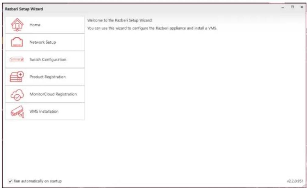
text_image
Razberi Setup Wizard Home Network Setup Switch Configuration Product Registration MonitorCloud Registration VMS Installation Welcome to the Razberi Setup Wizard: You can use this wizard to configure the Razberi appliance and install a VMS. ✓ Run automatically on startup v2.2.0.9512.9.1 U1, U2, and SFP 2 Network Setup
To change the devices IP addresses of Uplink 1, Uplink 2, or SFP2 using the Setup Wizard two conditions apply. First the NIC adapter must be enabled and second it must be connected to an active network. Otherwise, you must use the Windows Network Connections settings screens to make network changes. Provided the previous conditions apply, users may select the Network Setup tab and begin to change the settings of Uplink 1, Uplink 2, and SFP 2.

text_image
Razberi Setup Wizard Home Network Setup Switch Configuration Product Registration VMS Installation Note: The Uplink NIC adapters must be enabled in Windows and have an ethernet cable connected in order for the configuration to be applied properly. Uplink 1 IP configuration: Static IP Address: 192.168.50.19 Subnet Mask: 255.255.255.0 Gateway: 0.0.0.0 DNS Server 1: fec0:0:0:ffff:1%1 DNS Server 2: fec0:0:0:ffff:2%1 Uplink 2 IP configuration: Static IP Address: 10.0.10.98 Subnet Mask: 255.255.255.0 Gateway: 10.0.10.1 DNS Server 1: 10.0.10.11 DNS Server 2: 0.0.0.0 Refresh Apply Changes ✓ Run automatically on startup v1.2.1.5302.9.2 Switch Configuration
If the administrator of ServerSwitchIQ forgets the username, password, and/or network settings of the switch, an administrator of the server may view the network settings of the switch and reset the switch to its factory defaults – including the default username and password using the Setup Wizard.
Users simply select the Setup Wizard desktop icon, open the application and select the Switch Configuration Tab as shown below:

text_image
Razberi Setup Wizard Home Network Setup Switch Configuration Product Registration VMS Installation Switch IP configuration: Static IP Address: 192.168.50.1 Subnet Mask: 255.255.255.0 Gateway: DNS 1: DNS 2: Switch administration: Open Switch Webpage Reboot Switch Reset to Factory Defaults Refresh Apply Changes ✓ Run automatically on startup v1.2.1.5302.9.3 Product Registration
It is important to register your ServerSwitchIQ to obtain notification and access to product and firmware updates; obtain new documentation; and to reach you with important product information.
Note: Ensure that your device is connected to the Internet prior to submitting the registration information. Fill out the form below as shown and hit submit.

text_image
Razberi Setup Wizard Home Network Setup Switch Configuration Product Registration VMS Installation Thank you for purchasing a Razberi ServerSwitchIQ™ appliance. You are joining a great community and we appreciate your business. Benefits of registering the product: • Notification and access to product and firmware updates • User guide and documentation updates • Ability to reach you to share important information Ensure your Razberi ServerSwitchIQ™ is connected to the internet prior to submitting. Please enter the contact information of the party who should get notifications of firmware upgrades: *First Name: *Last Name: *Email: *Company: Country: United States User Type: End User ✓ Do you want to stay up to date on the latest Razberi news and offers? Submit Registration ✓ Run automatically on startup v1.2.1.5302.9.4 Razberi MonitorCloud™ Account Registration
Razberi MonitorCloud is a licensed cloud-based health monitoring feature available on all Razberi ServerSwitchIQ™ appliances. It monitors the performance and cybersecurity of the surveillance system and appliances. MonitorCloud™ reduces the risk of downtime, lost video, and cybersecurity threats. Users can set up alerts that proactively send SMS texts or email notifications when storage errors, network issues, malware, or cyber threats are detected. Ensure your Razberi has connectivity to the internet and select the “Register for MonitorCloud” button to request a user account within MonitorCloud. Once you have a company account within MonitorCloud you can add individual ServerSwitchIQ devices, EndpointDefenders, and Core™ devices and add other users for automated health monitoring.
Use your login credentials to register your Razberi within the Razberi Monitor service, MonitorCloud tab running on your Razberi or from your Monitor Account use the Razberi List page along with the model and serial number of your Razberi to add units to this secure service.
The Razberi Monitor agent service and MonitorCloud uses TLS v1.2 for transmission encryption that is done over TCP port 443 – an industry best practice for ensuring secure and safe
connectivity to the internet. All communications with the cloud are initiated by the Razberi Monitor service.
2.9.5 VMS Installation
ServerSwitchIQ supports a wide variety of world class video management software (VMS) solutions. The Setup Wizard is an application residing on the ServerSwitchIQ for helping user install the VMS of their choice. Start by selecting the VMS Installation tab on the right. This will open a screen with a list of VMS providers available. Simple select the vendor of your preference to begin the installation processes. Note that the Razberi ServerSwitchIQ does not come with the license key for these third-part VMS providers, so have that handy to activate the software. After installation is complete, please contact the VMS provider direction for the most up-to-date information of functionality and operation. Razberi endeavors to update the installer packages every four months however VMS providers may have released a patch or update during this time frame. Please consult the VMS providers web site for more details on activating and updating their software.
3| Server Management
Your ServerSwitchIQ includes a server running a Windows operating system (Linux is optional). It is beyond the scope of this document to detail how to best manage these servers, however, there are a few key points to consider.
- Follow corporate policies for assigning admin and user accounts.
- The server has its own U2 network connection for accessing the server and any software residing on it.
• The administrator of the server should also have administrator privileges on the switch.
- Server administrators can use the Setup Wizard to view basic network settings of the switch, reboot, and reset the switch to its factory defaults. Careful planning is required to avoid unnecessary loss of video data.
- Systems integrators should review the appendix of this document for examples of how the server and switch can be deployed to meet the needs of various scenarios.
• If your ServerSwitchIQ included Cylance Anti-Virus software read the next section.
3.1 Server Anti-Virus Software
If your model of ServerSwitchIQ includes the Cylance Anti-Virus software you will want to become familiar with its features and benefits. Key features and benefits include:
- Low CPU Utilization. Cylance PROTECT® only uses 1 to 3% of the CPU.
- Low Memory Footprint. Cylance PROTECT® typically uses 40 – 60 MB of memory.
- Low or No Internet Traffic. Cylance's Artificial Intelligence capability means it does not need an internet connection to detect threats, unlike signature-based products. When an internet connection is provided, updates from Razberi to the unit's profile are made for whitelisting new applications and updated versions of VMS software.
- Tuned to your VMS and its updates. Cylance PROTECT® has been tested with all the VMS' supported by the Razberi Setup Wizard. Razberi regularly conducts tests with each of the VMS' we provide on our device. Razberi performs updates as new versions of VMS' are released on regular basis.
- Tailored to your Locked Down Image. If you want to ensure Cylance PROTECT® is tuned to specialized software you want to add to your Razberi appliance, you may need to whitelist scripts or services. To do so, contact Razberi support and connect CylancePROTECT® to the Internet for receiving updates and to authorized software it may initially quarantine.
3.1.1 Validating Cylance Installation
Some models of the Razberi appliances come with Cylance preinstalled. You can verify Cylance is installed by looking for a small green shield in the Windows tool bar and right clicking on "About". This should launch the following screen:

text_image
About Cylance Protect CYLANCE PROTECT Version 2.0.1440.41 Policy AQT-MP-block SC alert (Online) Copyright (C) Cylance 2017 Cylance, Inc. Current as of: 6/26/2017 2:18:08 PM Policy last updated:: 6/22/2017 7:46:26 AM Serial Number:aa15ec4e-7d86-4521-9714-0ce683e86f03 OKOn this screen you'll see the version of CylancePROTECT®, the date when Cylance was last updated, the custom security policy Razberi applied, and when that policy CylancePROTECT® was last updated. Connecting CylancePROTECT® to the internet, while not required, does have benefits as outlined in the next section.
3.1.2 Receiving Cylance PROTECT® Updates
Cylance was designed to not require internet connectivity or updates on a regular basis. It's Artificial Intelligence and Machine Learning algorithms means your VMS server will remain protected without internet connectivity.
That said, there are several benefits for connecting Cylance to the internet such as 1) wanting to authorize quarantined files that are added over time, 2) updating all of your SSIQ to the same version of Cylance for consistency between units, 3) enjoy future integration with VyneWatch appliance health monitoring and alerting, and 4) to enjoy even better AI / Machine Learning capabilities that evolve over time.
Regardless of the reason, updates can be securely received within a few minutes by simply connecting the Razberi appliance to the internet and selecting “Check for Updates” and “Check for Policy Updates”. The CylancePROTECT agent uses SSL/TLS v1.2 for transmission encryption that is done over TCP port 443 – an industry best practice for ensuring secure and safe connectivity to the internet.
3.1.3 Receiving Cylance PROTECT® Malware Alerts
Cylance PROTECT® is integrated with Razberi Monitor™ providing you centralized, real-time notification of cyber threats to Razberi ServiceSwitchIQ™ and Core™ appliances.
3.1.4 Authorizing Quarantined Files, Scripts, Services
The security policy that is installed on your Razberi appliance was created by Razberi after validating it against all the VMS we provide for installation. Additionally, we check for the safe operation of services that the Windows operating system needs. In the event you want to install other software, run scripts, or run special services and they are quarantined by Cylance PROTECT® you must update your security policy for that appliance. To do so first contact Razberi support and request your Cylance PROTECT® Security Profile be updated. Your Razberi will need to be connected to the internet so Razberi can review, approve, and provide the new Security Profile for your devices.

text_image
PROTECT DESKTOP-T49IEJ4 Threats Exploits Events Scripts External Devices File Category Found ID [Quarantined:]\cloudberrybatchinstall.exe Quarantined 1 7A6574E21... [Quarantined:]\SetupVS.exe Quarantined 1 F15A0125F... Analyzed Files: 40787 Quarantined: 2Here we have two files that were quarantined. To authorize these, contact Razberi customer support at sakesinfo@razberi.net or call 1-469-828-3380 and ensure your Razberi is on the internet for scheduling a custom security profile update.
4| EndpointDefender
4.1 EndpointDefender Product Overview
Razberi EndpointDefender is a plug-and-play network appliance that delivers the award-winning Razberi CameraDefense™ solution to harden cameras and networks from cybersecurity threats. More than a PoE switch, EndpointDefender can be deployed in minutes to automate best practices for protecting cameras while providing PoE and a secure ethernet connection to any IoT device. By using Razberi Monitor™, security leaders receive alerts of issues providing assurance that cameras are healthy and secured.
The ServerSwitchIQ running Razberi Monitor is used to manage one or more EndpointDefenders and the switch of the ServerSwitchIQ. Currently, up to eight (8) EndpointDefenders can be managed by one instance of Razberi Monitor on a ServerSwitchIQ. However, please note the following:
While up to eight EndpointDefenders can be managed by one instance of Razberi Monitor running on a ServerSwitchIQ, you need to ensure video traffic does not exceed the internal 1Gb link between the switch and the server hosting the VMS in a ServerSwitchIQ. Use the Outbound and Inbound Server Traffic indicators on the Overview page of the ServerSwitchIQ Switch Web interface for knowing when you are about to exceed its limits.
4.1.1 Network Protocol and Port Requirements
The network connection between the EndpointDefender and managing ServerSwitchIQ must allow the following protocols and ports:
- HTTPS (TCP port 443) for secure alert and device health data collection to Razberi MonitorCloud (optional)
- HTTPS (TCP port 8443) for secure alert, device health, and audit log data collection
- HTTPS (TCP port 18128) for accessing Razberi Monitor web page remotely (optional)
- SSDP (UDP port 1900) for the initial discovery of EndpointDefenders by Razberi Monitor on its Add Devices page
Please see the EndpointDefender and Razberi Monitor User Guide for more details on how to setup, manage, and deploy these solution components.
5| APPENDIX
5.1 APPENDIX A: Frequently Asked Questions (FAQ)
5.1.1 General Questions
- Q Is Razberi™ a server or a switch?
A The Razberi™ is a purpose-built server with an embedded L2 managed PoE switch that runs on Windows providing flexibility in scale and application.
- Q Is Razberi™ an L3 switch?
A No, the embedded managed PoE switch found within Razberi ™ is an L2 device.
- Q Is Razberi™ a router?
A No, However, it does have certain common characteristics sometimes associated with L3 switches / routers such as VLAN and DHCP services.
- Q How much memory does Razberi™ ServerSwitchIQ™ come with?
A 4/8/16GB - based on model selection.
- Q What mounting options are available?
A Desktop, wall, and rack mounting options are available.
- Q What is a distributed architecture?
A It is a method of installation in which units are installed within IDF closets, floors, buildings or in some other spread-out method.
- Q What benefits exist in using a distributed architecture installation?
A 95% reduction in bandwidth and IP address usage compared to a centralized installation.
- Q Is CameraDefense and CylancePROTECT® installed on every Razberi?
A Professional and Enterprise versions of Razberi include CameraDefense and CylancePROTECT®.
5.1.2 Video Management Software (VMS)
- Q What video management software (VMS) systems are compatible with Razberi™ ServerSwitchIQ™?
A VMS software provided by 3VR, Avigilon, Axis, Digiop, Exacq, Genetec, Ipconfigure, ISS, Lenel, Milestone, OnSSI, Verint and many others. Check our support page for recent certifications and updates.
- Q Does the Razberi™ ServerSwitchIQ™ already come pre-loaded with these VMS options?
A No. However, a VMS wizard with these certified options are located on the desktop for installer selection.
- Q Does the Razberi™ ServerSwitchIQ™ come pre-licensed with these VMS options?
A No. Only the files necessary for installing the VMS through the VMS wizard. Licenses are acquired independently of your ServerSwitchIQ™ purchase.
- Q What if my VMS preference is not offered within the VMS wizard selections, can I install a different VMS?
A Yes. You are not limited to those selections offered through the VMS wizard. But care should be taken to ensure that software requirements are met by the ServerSwitchIQ™ model.
- Q I noticed that the versions of the VMS offered through the wizard are outdated; am I limited to these versions or can I install the latest versions from the VMS provider?
A No, you are not limited to the versions of video management software offered through the wizard.
- Q If I have any questions regarding VMS licensing or software related problems, who should I call for help?
A Software related questions regarding any of the VMS options offered should be directed to appropriate support channels from the software provider.
5.1.3 Operating System
- Q What operating systems does the Razberi™ ServerSwitchIQ™ come with?
A Windows 10 Enterprise LTSB (Default). Options Include: Windows 2008 r2, Linux (Ubuntu).
- Q Does the Razberi™ ServerSwitchIQ™ use 32b or 64b OS?
A 64b OS
- Q What processors does the Razberi™ ServerSwitchIQ™ use?
A Intel Haswell iCore3/5/7 - based on model selection.
5.1.4 Cameras and Video
- Q Can I connect a monitor to the Razberi™ ServerSwitchIQ™ and use it as a video client station?
A Yes, it's possible to view video directly off of the HDMI / VGA monitor output on the unit itself.
- Q Are there any restrictions or limitations on how many cameras I can view directly from the Razberi™ ServerSwitchIQ™?
A Yes. However, most major VMS providers allow you to create at least two profiles (viewing & recording), which can be used to lighten the load of displaying video. Others take advantage of Intel's Haswell Quick Sync Video technology that greatly enhances the unit's ability to display video directly from the HDMI output.
- Q What is Intel Quick Sync Video?
A It's the name given to Intel's hardware video encoding and decoding technology integrated into some of its CPUs, like those from the Haswell family of processors.
- Q How does Intel Quick Sync Video help?
A Intel® Quick Sync Video integrated into select Intel® processors provides fluid display of video at full HD (1920x1080 @ 30 frames per second), from as many as 25 cameras at the same time on a cost-effective, single-socket, four-core client power by a high-end Intel® Core™ i7 processor.
- Q How many cameras can I connect to a single Razberi™?
A The ServerSwitchIQ™ comes in different port configurations 8/16/24, but additional cameras can be "streamed" to it via network connections.
- Q How much storage do I need for video recording?
A Video storage calculations are best done using tools provided by the VMS providers and then compared to storage options offered by ServerSwitchIQ™ models.
- Q What is the maximum storage available?
A The ServerSwitchIQ™ Enterprise has a native storage capacity of 64TB. See model specifications for the storage capacity of each type of Razberi unit.
5.1.5 Redundant Array of Independent/Inexpensive Disks (RAID)
- Q Does Razberi™ support RAID configurations?
A Yes, RAID configurations are available on certain models; several offer RAID 0/1/5/6/10 as possible alternatives.
- Q How do I know which RAID configuration is best?
A RAID was designed to provide efficiencies, redundancies and fault tolerances based on selection, check with your VMS provider to determine best options.
- Q Is RAID5/6 recommended?
A RAID5/6 is not recommended by several HW/SW providers for "live" databases due to the mega pixel video stream size, frequency, and potential disk array rebuild time, which can significantly alter access time when playing back video. However, when applicable, it can be a viable solution for long-term storage like those used by archive servers.
- Q How much storage is available for video recording when using RAID?
A Sample calculation - ServerSwitchIQ™ Enterprise 2RU (8 HDD x 8TB) - RAID0=64TB, RAID1=32TB, RAID5=56TB, RAID6=48TB, RAID10=32TB. More details can be provided by contacting your Razberi™ support channel for further model specific discussion.
5.1.6 Power Supply
- Q Is there a redundant power supply option?
A Yes. Some ServerSwitchIQ™ models come with a "built in" redundant power supply, while others use an external power supply for redundancy.
- Q How many units can be connected to the external redundant power supply?
A Three. The Enterprise 1RU model has an external connector that can be wired directly to 1 of 3 ports on a single 1RU redundant power supply.
5.1.7 Power over Ethernet (PoE)
- Q Does Razberi™ support PoE Plus?
A Yes, all models support 802.AF and 802.AT specifications for PoE distribution.
- Q What is the maximum PoE output per port?
A 30W
- Q What is the maximum PoE budgeted power?
A Model specific. For example, the ServerSwitchIQ™ Enterprise models can go as high as 650W, while the ServerSwitchIQ™ Rugged can reach up to 200W.
- Q Are the PoE ports 10/100 or 10/100/1000?
A 10/100
- Q What happens when you exceed the PoE power budget with new devices?
A New PoE devices can still be connected, but they will not be given power from the PSE Controller. It would be best to disable PoE on that port and consider using a PoE injector near the switch or near the end point.
- Q How does the switch behave adding new PoE devices when the load is getting close to the total power budget?
A Once the remaining power budget is below 32 watts and a new device that is identified as a Class 4 device is connected, the switch will not power the device. The corresponding LED for that port will flash to indicate the device is not being provided PoE. The same goes for Class 1(4w), Class 2 (7w) and Class 3(15.4w) devices. Unidentified class devices may register as a class 0 (15.4w). The full class definition is required to bring a new device online, even if that device uses less than its class specification (a class 3 device may only ever use 9Watts, 15.4 are still required to connect it as a new device.
- Q What happens if all ports are being used for PoE, the wattage of existing PoE devices fall within the power budget, then suddenly the usage increases beyond the total power budget (e.g., due to adding additional peripherals)? How will the ServerSwitchIQ manage this scenario.
A When all the ports of the device are in use for PoE, the device will sense that the power budget has been exceeded and will turn of PoE Port with the highest number port. For example, port 8 on an 8 port device, port 16 on a 16 port device.
- Q What happens if only some of the ports are being used for PoE, the wattage of the existing PoE devices falls within the power budget, and suddenly the usage from one port increases beyond the total power budget?
A For example, if 13 ports of a 16 port device are in use, and any one of those 13 ports causes the PoE Budget to be exceeded the device will bring the power usage back within the PoE budget. This is done by turning off power to the highest numbered port. In this scenario Port 13 will be turned off.
5.1.8 Uplink Ports
- Q Are the uplink ports 10/100 or 10/100/1000?
A 10/100/1000
- Q Does the uplink ports support fiber connections?
A Yes, all models have two 1G uplink ports that support multi-mode and single-mode SFP modules. The SFP1 is a combo port such that either it or U1 can be active, but not both at the same time. SFP2 and U2 can both be active at the same time.
- Q Do I need to purchase specific SFP modules, are the ports locked or "keyed" to certain manufacturers?
A No. However, special care should always be taken to determine your fiber installation needs and proper accommodation taken.
- Q Can I connect 2 or more appliances like a daisy chain using the uplink ports?
A This is not recommended and is likely not practical. Razberi™ is best used when installed within a distributed architecture. (See 4.1.1 General questions.)
- Q How can I determine how much power is being consumed by a particular PoE port?
A Information regarding PoE power consumption can be obtained by accessing the switch web interface.
- Q How do I secure individual PoE ports for cyber security?
A Device Binding is the access control feature that is available through the switch web interface to lock down ports to specific MAC IDs.
- Q How do I set the power restriction by port?
A By accessing the PoE/Cable section within the switch web interface, power consumption can either be auto-negotiated or manually set, as you prefer. Take care not to limit power below PoE device power requirement; failure to do so may cause adverse effects in the device's functionality.
- Q Can a particular port or the entire switch be reset without rebooting Windows?
A Yes, the ServerSwitchIQ appliances were design to provide independent functionality to introduce robustness to their operations. Although resetting ports, or the entire switch, has no impact on Windows, it will cause interruptions in video recording.
- Q Where do I go to determine the amount of bandwidth being consumed by particular ports?
A The ServerSwitchIQ web interface under the initial status screen provides an overview of power and bandwidth consumption.
- Q Do I need to create a VLAN in order to isolate the camera traffic?
A No. All ServerSwitchIQ appliances were design with an internal VLAN (U1 & PoE Ports), this provides segmentation of traffic and eliminate direct accessibility of devices (cameras, encoders, etc.).
5.1.9 Razberi MonitorCloud
- Q How do I acquire a Razberi MonitorCloud user account?
A You can request on from the Razberi web site, from the Setup Wizard, you can contact customer support at +1 469-828-3380, or send a request to salesinfo@razberi.net to obtain your Razberi MonitorCloud account.
- Q What is the process for registering a Razberi™ to my Razberi MonitorCloud™ account?
A On the Razberi appliance desktop, click on the Razberi Monitor icon to open the application. Select "Razberi MonitorCloud" and complete the requested information to register the Razberi and begin using MonitorCloud to proactively monitor the health of your surveillance system. A second method is to access your MonitorCloud user account, go to the Razberi List page and add the unit. If your ServerSwitchIQ device has access to the internet and if you did not disable the MonitorCloud feature simply select "Register Razberi" from the Razberi list page. Complete the information below from your SSIQ:
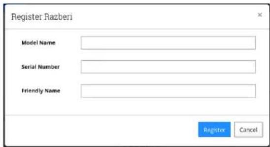
text_image
Register Razberi Model Name Serial Number Friendly Name Register Cancel- Q What is the port, bandwidth usage, and update frequencies used by MonitorCloud?
A 443 is the port used by Razberi Monitor and MonitorCloud using Transport Layer Security encryption 1.2. The typical bandwidth is only 10 KB every 5 minutes. Razberi Monitor update frequency is every 5 minutes.
- Q What alerts can I create within MonitorCloud™?
A There are 12 alerts: Hard drive failure, RAID failure, CPU Temperature, Excessive Switch Traffic, EndpointDefender Offline, ServerSwitchIQ offline, Switch Offline, Malware Protection, Unauthorized Device, Default Password, Common Password, and Whitelist Violation.
5.1.9 CameraDefense and Cylance
- Q I am installing an application on my Razberi SSIQ and Cylance has quarantined it as an Exploit, Threat, or Script. What do I need to do so I can install my application software?
A First, determine that the software or application you are trying to install is from a reputable source. You will need to contact Razberi Technical Support at either technicalsupport@razberi.net or call 1-469-828-3380, Option 4. Provide the file name in which you want to be allowed to run. The Razberi appliance you are installing the software or application on will need to be connected to the internet so the Cylance Security profile can be updated to waive the file.
- Q The CameraDefense Dashboard, Device Binding show a yellow/warning state. After checking the Device Binding configuration, all known MAC addresses are bound correctly. Why am I getting this warning?
A This may be due to ports that are active but are not in use and need to be disabled. Click on the Overview tab, and ensure any inactive ports are disabled. Enabling a port with no device attached (link is in a down state) will cause this yellow warning state.
- Q I completed the CameraDefense wizard and is now running. After saving my cameras are no longer streaming to the VMS, no live or recorded video.
A This may be due to your firewall or whitelist configuration. RTSP needs to be enabled for most cameras to steam video. To verify, go to the Dashboard, click on Configure under the Firewall and disable, save. Do the same for Whitelist, disable and save. Check to see if video is now streaming.
- Q I ordered an SSIQ Standard model and it does not have CameraDefense or CylancePROTECT® installed on it. How can I get this added to my SSIQ Standard Product?
A Contact your Dealer or Integrator, or you can contact Razberi Technologies at 1-469-828-3380 or email salesinfo@razberi.net
- Q I have added a new camera or device, correctly bound the new device with Device Binding but my camera discovery software is unable to see the camera.
A The discovery protocol for finding the device may be blocked by the firewall in CameraDefense. Open CameraDefense, click on the Firewall configuration and add the Bonjour discovery service to the device group where the new device resides. Another way is to disable the Firewall completely for a brief time and complete your discovery and then enable the Firewall back, save. If you add Bonjour, make sure you disable it after finding the device to reduce that as an attack vector for cyberattacks.
5.1.9 EndpointDefender
- Q How many EndpointDefenders can be managed by one Razberi?
A Up to eight (8) EndpointDefenders can be managed by one instance of Razberi Monitor running on a Razberi ServerSwitchIQ or Core appliance. Take care to ensure the camera traffic from the EndpointDefender does not exceed the 1Gb internal traffic limit between the server and switch of the ServerSwitchIQ. The Core appliance has a much higher traffic limit (10Gb per NIC).
- Q How do I manage my EndpointDefender from a ServerSwitchIQ or Core appliance?
A You can manage individual EndpointDefenders by browsing to their web interface, however Razberi Monitor is an application that runs on ServerSwitchIQ and Core allowing
you to manage and monitor up to eight EndpointDefenders and must be used to receive proactive alerts and audit log reports.
- Q How do I configure and manage the EndpointDefender?
A EndpointDefenders can be configured via their web interface and behave like the switch within the ServerSwitchIQ.
- Q Does MonitorCloud and VMS Integrated Alerting work with the EndpointDefender?
A Yes. If your EndpointDefender is registered with the Razberi Monitor agent it will report CameraDefense alerts to both MonitorCloud and any selected VMS.
- Q What are the limitations when connecting cameras to the EndpointDefender?
A The number of ports and PoE it provides depends on the model. The maximum bandwidth is 1 gigabit / second.
- Q What are the PoE budgets for the EndpointDefender?
A The 8 port supports up to 140W and the 16 port EndpointDefender supports up to 277W.
- Q Are the EndpointDefender management and alerting communications encrypted between the Razberi Monitor and EndpointDefender?
A The configuration, management, alerting, and audit log communications between the SSIQ and EndpointDefender are encrypted using industry standards HTTPS / TLS 1.2 / AES-256.
5.2 APPENDIX B: Network Configuration Types
There several ways to configure your network. The following are some examples of common configurations.
5.2.0.1 DISTRIBUTED VS. GENERALIZED INSTALLATIONS - OVERVIEW
Distributed installations spread the processing burden across many devices in the field, which can enhance overall reliability and minimize system vulnerability. A generalized or centralized installation connects all related devices to a single processing/control point.
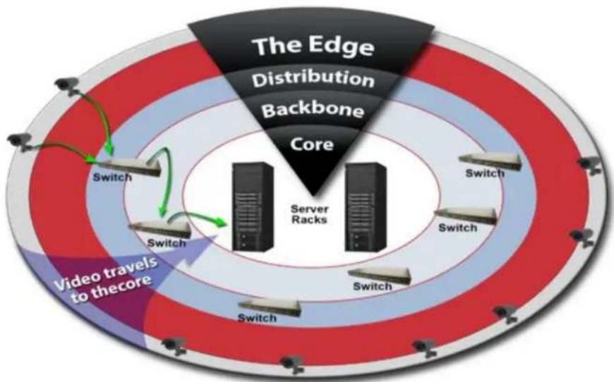
flowchart
graph TD
    A["Server Racks"] --> B["Switch"]
    A --> C["Switch"]
    A --> D["Switch"]
    A --> E["Switch"]
    A --> F["Switch"]
    A --> G["Switch"]
    style A fill:#f9f,stroke:#333
    style B fill:#ccf,stroke:#333
    style C fill:#ccf,stroke:#333
    style D fill:#ccf,stroke:#333
    style E fill:#ccf,stroke:#333
    style F fill:#ccf,stroke:#333
    style G fill:#ccf,stroke:#333
    subgraph Core
        H["The Edge Distribution Backbone"]
        I["Video travels to thecore"]
    end
5.2.1 Centralized Configuration
A centralized configuration...
- Is bandwidth intensive
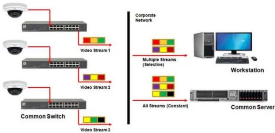
flowchart
graph TD
    A["Security Camera"] --> B["Video Stream 1"]
    C["Security Camera"] --> D["Video Stream 2"]
    E["Security Camera"] --> F["Video Stream 3"]
    G["Common Switch"] --> H["Video Stream 3"]
    B --> I["Corporate Network"]
    D --> I
    F --> I
    I --> J["Multiple Streams (Selective)"]
    I --> K["All Streams (Constant)"]
    J --> L["Workstation"]
    K --> M["Common Server"]
- Requires a lot of IP addresses (1:1 ratio)
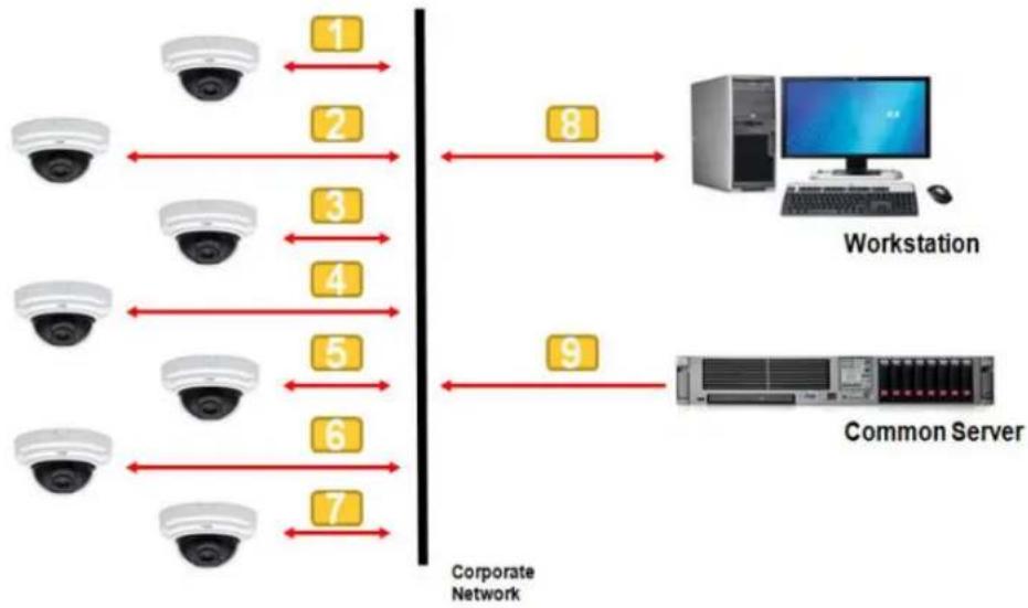
flowchart
graph LR
    A["Camera 1"] --> B["Workstation"]
    C["Camera 2"] --> B
    D["Camera 3"] --> B
    E["Camera 4"] --> B
    F["Camera 5"] --> B
    G["Camera 6"] --> B
    H["Camera 7"] --> B
    I["Workstation Server"] --> J["Common Server"]
    style A fill:#f9f,stroke:#333
    style C fill:#f9f,stroke:#333
    style D fill:#f9f,stroke:#333
    style E fill:#f9f,stroke:#333
    style F fill:#f9f,stroke:#333
    style G fill:#f9f,stroke:#333
    style H fill:#f9f,stroke:#333
    style I fill:#ccf,stroke:#333
    style J fill:#ccf,stroke:#333
- Often has a single point of failure
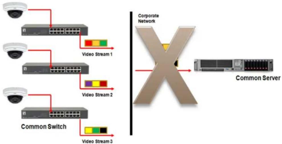
flowchart
graph TD
    A["Security Camera"] --> B["Server 1"]
    C["Security Camera"] --> D["Server 2"]
    E["Security Camera"] --> F["Server 3"]
    G["Common Switch"] --> H["Video Stream 1"]
    I["Common Switch"] --> J["Video Stream 2"]
    K["Common Switch"] --> L["Video Stream 3"]
    B --> M["Corporate Network"]
    D --> M
    F --> M
    H --> M
    J --> M
    L --> M
    M --> N["Common Server"]
5.2.2 Distributed Configuration
A distributed configuration is ideal for systems of any size, especially large systems.
A distributed method of configuration...
1. Reduces bandwidth consumption
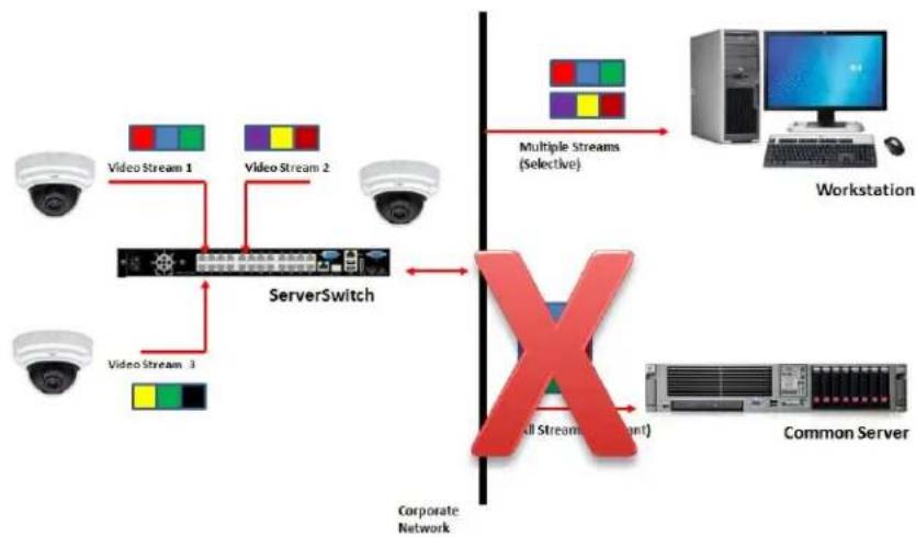
flowchart
graph TD
    A["ServerSwitch"] --> B["Workstation"]
    A --> C["Common Server"]
    D["Video Stream 1"] --> E["ServerSwitch"]
    F["Video Stream 2"] --> E
    G["Video Stream 3"] --> E
    H["Multi Streams (Selective)"] --> I["Workstation"]
    J["All Streams (Target)"] --> K["Common Server"]
    L["Corporate Network"] --> M["X"]
    style A fill:#f9f,stroke:#333
    style B fill:#ccf,stroke:#333
    style C fill:#cfc,stroke:#333
    style D fill:#fcc,stroke:#333
    style E fill:#cff,stroke:#333
    style F fill:#ffc,stroke:#333
    style G fill:#fcc,stroke:#333
    style H fill:#fcc,stroke:#333
    style I fill:#ffc,stroke:#333
    style J fill:#fcc,stroke:#333
    style K fill:#ffc,stroke:#333
    style L fill:#fcc,stroke:#333
2. Reduces the number of IP addresses needed (1:24)
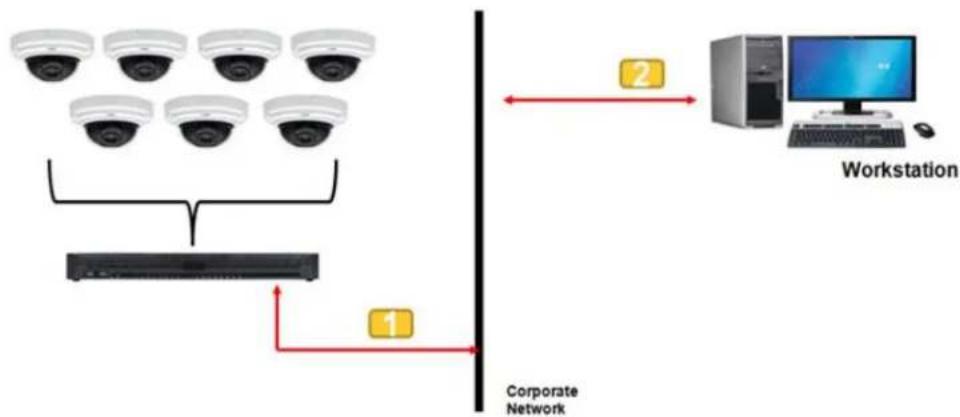
flowchart
graph TD
    A[" surveillance cameras"] --> B[" computer"]
    C[" surveillance cameras"] --> B
    D[" surveillance cameras"] --> B
    E[" surveillance cameras"] --> B
    F[" surveillance cameras"] --> B
    G[" surveillance cameras"] --> B
    H[" surveillance cameras"] --> B
    I[" surveillance cameras"] --> B
    J[" surveillance cameras"] --> B
    K[" surveillance cameras"] --> B
    L[" surveillance cameras"] --> B
    M[" surveillance cameras"] --> B
    N[" surveillance cameras"] --> B
    O[" surveillance cameras"] --> B
    P[" surveillance cameras"] --> B
    Q[" surveillance cameras"] --> B
    R[" surveillance cameras"] --> B
    S[" surveillance cameras"] --> B
    T[" surveillance cameras"] --> B
    U[" surveillance cameras"] --> B
    V[" surveillance cameras"] --> B
    W[" surveillance cameras"] --> B
    X[" surveillance cameras"] --> B
    Y[" surveillance cameras"] --> B
    Z[" surveillance cameras"] --> B
    AA[" surveillance cameras"] --> B
    AB[" surveillance cameras"] --> B
    AC[" surveillance cameras"] --> B
    AD[" surveillance cameras"] --> B
    AE[" surveillance cameras"] --> B
    AF[" surveillance cameras"] --> B
    AG[" surveillance cameras"] --> B
    AH[" surveillance cameras"] --> B
    AI[" surveillance cameras"] --> B
    AJ[" surveillance cameras"] --> B
    AK[" surveillance cameras"] --> B
    AL[" surveillance cameras"] --> B
    AM[" surveillance cameras"] --> B
    AN[" surveillance cameras"] --> B
    AO[" surveillance cameras"] --> B
    AP[" surveillance cameras"] --> B
    AQ[" surveillance cameras"] --> B
    AR[" surveillance cameras"] --> B
    AS[" surveillance cameras"] --> B
    AT[" surveillance cameras"] --> B
    AU[" surveillance cameras"] --> B
    AV[" surveillance cameras"] --> B
    AW[" surveillance cameras"] --> B
    AX[" surveillance cameras"] --> B
    AY[" Workstation "]
- Distributes risk and scales better

text_image
Switch & Windows function independently of one another, avoids bottle necks and potential loss of all video by not requiring centralized recording.5.2.2.1 EXAMPLES OF DISTRIBUTED CONFIGURATIONS
- Single Unit Installation – Separate Camera Network
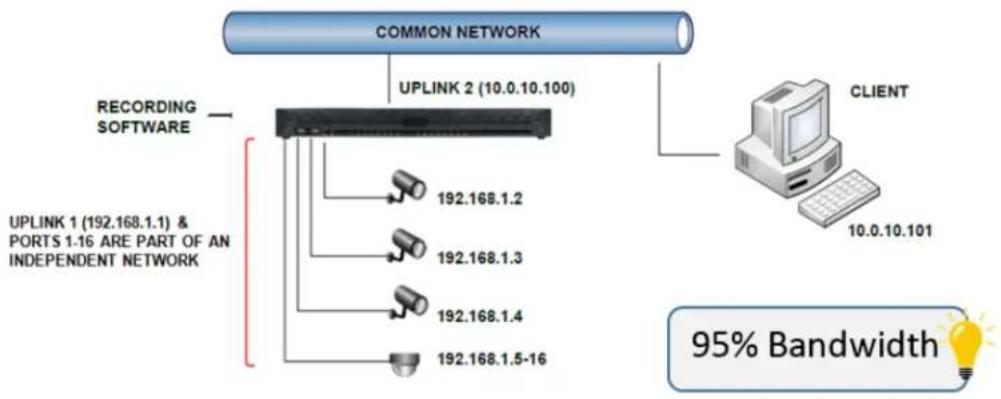
flowchart
graph TD
    A["COMMON NETWORK"] --> B["UPLINK 2 (10.0.10.100)"]
    B --> C["192.168.1.2"]
    B --> D["192.168.1.3"]
    B --> E["192.168.1.4"]
    B --> F["192.168.1.5-16"]
    G["RECORDING SOFTWARE"] --> B
    H["CLIENT"] --> I["10.0.10.101"]
    I --> J["95% Bandwidth"]
    style A fill:#f9f,stroke:#333
    style G fill:#ccf,stroke:#333
    style H fill:#cfc,stroke:#333
- Single Unit Installation – Flat Network

flowchart
graph TD
    A["COMMON NETWORK"] --> B["UPLINK 1 (192.168.1.1)"]
    A --> C["POE SWITCH 192.168.1.17-18"]
    A --> D["RECORDING SOFTWARE"]
    D --> E["192.168.1.2"]
    D --> F["192.168.1.3"]
    D --> G["192.168.1.4"]
    D --> H["192.168.1.5-16"]
    A --> I["CLIENT 192.168.1.19"]
    style A fill:#cce5ff,stroke:#333
    style B fill:#cce5ff,stroke:#333
    style C fill:#cce5ff,stroke:#333
    style D fill:#e6f3ff,stroke:#333
    style E fill:#fff2cc,stroke:#333
    style F fill:#fff2cc,stroke:#333
    style G fill:#fff2cc,stroke:#333
    style H fill:#fff2cc,stroke:#333
    style I fill:#fff2cc,stroke:#333
- Multiple Units – Separate Camera Network

flowchart
graph TD
    A["VMS CLIENT STATIONS"] --> B["COMMON NETWORK 10.6.10.X"]
    B --> C["UPLINK 2 (10.6.10.180)"]
    B --> D["UPLINK 2 (10.6.10.131)"]
    B --> E["UPLINK 2 (10.6.10.102)"]
    C --> F["INTERNAL INDEPENDENT CAMERA NETWORK"]
    D --> G["UPLINK 1 & PORTS 1-16 192.163.1.X STATICALLY ASSIGN"]
    D --> H["UPLINK 1 & PORTS 1-16 192.163.2.X STATICALLY ASSIGN"]
    D --> I["UPLINK 1 & PORTS 1-16 192.163.3.X STATICALLY ASSIGN"]
    style A fill:#f9f,stroke:#333
    style B fill:#ccf,stroke:#333
    style C fill:#cfc,stroke:#333
    style D fill:#cfc,stroke:#333
    style E fill:#cfc,stroke:#333
    style F fill:#ffc,stroke:#333
    style G fill:#ffc,stroke:#333
    style H fill:#ffc,stroke:#333
    style I fill:#ffc,stroke:#333
- Advanced Considerations – Port Forwarding
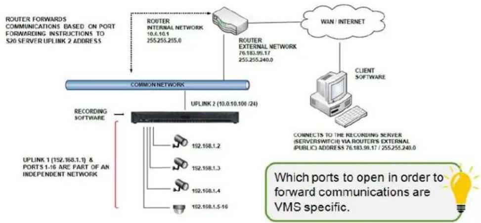
flowchart
graph TD
    A["ROUTER FORwards Communications Based on Port Forwarding Instructions to S20 SERVER UPLINK 2 ADDRESS"] --> B["ROUTER INTERNAL NETWORK 10.0.10.1 255.255.255.0"]
    B --> C["ROUTER EXTERNAL NETWORK 76.183.99.17 255.255.240.0"]
    C --> D["WAN / INTERNET"]
    D --> E["CLIENT SOFTWARE"]
    E --> F["CONNECTS TO THE RECORDING SERVER (SERVERSWITCH) VIA ROUTER'S EXTERNAL (PUBLIC) ADDRESS 76.183.99.17 / 255.255.240.0"]
    F --> G["UPLINK 2 (10.0.10.106/24)"]
    G --> H["RECORDING SOFTWARE"]
    H --> I["UPLINK 1 (152.168.1.1) & PORTS 1.16 ARE PART OF AN INDEPENDENT NETWORK"]
    I --> J["192.168.1.2"]
    I --> K["192.168.1.3"]
    I --> L["192.168.1.4"]
    I --> M["192.168.1.5-16"]
    J --> N["Which ports to open in order to forward communications are VMS specific."]