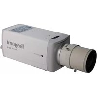
ISD-A21 - Security Camera Ikegami - Free user manual and instructions
Find the device manual for free ISD-A21 Ikegami in PDF.


| Product Type | Security Camera |
| Brand | Ikegami |
| Model | ISD-A21 |
| Image Sensor | 1/3-inch CCD |
| Resolution | 650 TVL |
| Minimum Illumination | 0.01 lux (F1.2) |
| Lens Type | Varifocal 2.8-12mm |
| Day/Night | Yes (IR cut filter) |
| Infrared Range | Up to 30 meters |
| Video Output | BNC (CVBS) |
| Power Supply | 12V DC, 500 mA |
| Power Consumption | 6 W |
| Dimensions (W x H x D) | 120 x 70 x 70 mm |
| Weight | 400 g |
| Housing Material | Aluminum die-cast |
| Weatherproof Rating | IP66 |
| Operating Temperature | -10°C to +50°C |
| Synchronization | Internal / Line lock |
| White Balance | ATW / Manual |
| Maintenance | Clean lens with soft cloth; check connections |
| Safety Precautions | Use only specified power adapter; avoid moisture |
| Spare Parts Available | Lens, IR board, power cable |
| Repairability | Modular design; replaceable components |
| Included Accessories | Mounting bracket, screws, power adapter |
Frequently Asked Questions - ISD-A21 Ikegami
User questions about ISD-A21 Ikegami
0 question about this device. Answer the ones you know or ask your own.
Ask a new question about this device
Download the instructions for your Security Camera in PDF format for free! Find your manual ISD-A21 - Ikegami and take your electronic device back in hand. On this page are published all the documents necessary for the use of your device. ISD-A21 by Ikegami.
USER MANUAL ISD-A21 Ikegami
OUTDOOR USE WARNING
WARNING - TO PREVENT FIRE OR ELECTRIC SHOCK, DO NOT
EXPOSE THIS APPLIANCE TO
RAIN OR MOISTURE.
Ikegami
Ikegami Tsushinki Co., Ltd.
Thank you very much for your wise choice of the Ikegami DPS Camera. Please carefully read this Instruction Manual to keep your camera at full capacity. This DPS camera is equipped with a 1/3" DPS CMOS sensor.
Contents
Page
- Handling precautions ...... E-1
- General E-1
- Features ...... E-2
- Names of parts and their functions ...... E-3
- Operation E-5
5-1.User setup E-5
5-2. SETUP switches and their functions ...... E-6
5-3. Entering the setup mode and its basics ...... E-6
5-4. Setup procedures ...... E-7
- Warranty and after-sale service E-15
- Specifications ...... E-16
- Appearance View
- Setup Menu

The exclamation point within an equilateral triangle is intended to alert the user to the presence of important operating and maintenance (servicing) instructions in the literature accompanying the appliance.
NOTE:
This equipment has been tested and found to comply with the limits for a Class A digital device, pursuant to Part 15 of the FCC Rules. These limits are designed to provide reasonable protection against harmful interference when the equipment is operated in a commercial environment. This equipment generates, uses and can radiate radio frequency energy and, if not installed and used in accordance with the instruction manual, may cause harmful interference to radio communications. Operation of this equipment in a residential area is likely to cause harmful interference in which case the user will be required to correct the interference at his own expense.
CAUTION;
ANY CHANGES OR MODIFICATIONS NOT EXPRESSLY APPROVED BY THE PART RESPONSIBLE FOR COMPLIANCE COULD VOID THE USERS AUTHORITY TO OPERATE THE EQUIPMENT.
Instructions for Disposal of Electric and Electronic Equipment in Private Household

Disposal of used Electric and Electronic Equipment
(Applicable in the European Union and other European countries with separate collection systems)
This symbol on the product, or in the related documents in the package, indicates that this product shall not be treated as normal household waste. Instead, it should be taken to a proper applicable collection point or depot for the recycling of electric and electronic equipment.
By ensuring this product is disposed of correctly, you will help prevent possible negative consequences for the environment and human health, which could otherwise be caused by inappropriate waste handling of this product. The recycling of materials will help to conserve natural resources.
For more detailed information about recycling of this product, please contact your local city authority, your household waste disposal service or the place where you purchased the product.
1. Handling precautions
- Do not install the camera in a water-splashed or highly humid place.
- Do not use the camera where the ambient temperature drops below -10°C or rises above +50°C . The images and component parts may be adversely affected or the camera may get in trouble.
- Never open the case of the camera because there are precision parts inside. Otherwise a trouble or accident may result.
- Do not put anything metallic and other foreign substances through the vent. A trouble, fire or electric shock may result.
- Be sure to turn off the power before installing or making connections.
- Do not install the camera in places exposed to vibrations and shocks.
- Be very careful not to drop or shock the camera while carrying it in.
- Do not touch the imaging device
- Do not orient the camera to the sun.
- Some types of lenses may cause hunting, light amount drop or other problems. In such case, readjust the lenses.
* Because of the digital image device characteristics, images may look rugged at high temperatures. This does not mean the camera is in trouble.
2. General
This color camera is provided with a 1/3-inch DPS CMOS sensor. The CCTV camera features wide dynamic range, high sensitivity and high resolution, and is equipped with the color/black-and-white switching, back-light compensation, automatic iris control, line lock and other functions. The unit is best suited for general surveillance.
Also equipped with the RS-485 communication function, the unit can be used to build an advanced surveillance system.
3. Features
(1) Wide dynamic range (WDR)
The WDR function provides for backlight compensation in a wide dynamic range. Being shot even in wide-illumination-fluctuating spots, bright-and-dark subjects can be captured clearly and in a natural look.
(2)Day/night switching function
High-quality color images are captured by day, whereas high-sensitivity monochrome pictures are taken at night. This automatic switching provides for crisp pictures without afterimage around the clock. Combined with an external sensor or the like, the switching pattern can also be controlled.
(3)Automatic white balance
Thanks to the automatic follow-up white balance control (ATW), the white balance adjusts itself no matter how greatly the subject's color temperature fluctuates.
(4)High-quality picture and high resolution
The camera is designed for smear-free imaging and low noise. The DSP (Digital Signal Processor) effectively enhances details, which achieves crisp and sharp images with high signal-to-noise ratio. The high resolution is backed up by a horizontal resolution of 520 TV lines and a vertical resolution of 400 TV lines.
(5)High sensitivity
Various modes of automatic gain control (AGC) are available to finely adjust the camera settings depending on the subject's illumination conditions. With the AGC and slow shutter in combination, high sensitivities of up to 0.03 lux/F1.4 are achieved.
(6)Camera setup function
The control buttons on the back of the camera enable to change and save the camera's settings.
(7) Two-way automatic iris control
This function is available to switch between video type iris lens and DC type iris lens. In other words, almost all types of CCTV automatic iris lenses can be employed.
(8) Flange focal distance adjusting mechanism
This mechanism makes it easy to readjust the focus tracking when a zoom lens is used.
(9)RS-485 communication function
The RS-485 communication function lets an external PC or the like control the camera, which helps configure an advanced surveillance system.
(10) Monitor selection function
The optimum picture quality can be selected according to the monitor used (CRT or LCD).
4. Names of parts and their functions

① Lens mount (CS mount)
This is used to mount the lens on the camera. Many types of CS mountlens can be attached.
② Flange focal distance adjuster
Used to readjust the flange focal distance (distance between lens mounting face and imaging area), if the camera fails to come into focus with the lens' focus ring.
③ Focus lock screw
Used to lock the camera's flange focal distance after is has been readjusted.
④ Holder mounting screw holes
These holes are used to fix the camera on the camera holder. They are also applicable to general tripods.
Note
To attach the camera on a tripod or a camera holder, be sure to use mounting screws. (1/4" -20UNC) that are shorter than 5.5 mm.
⑤ Lens selector switch
The switch has two positions, for a video iris lens and a DC iris lens.
⑥ Auto iris lens connector
Specifically used to connect the auto iris lens.
- For the video type auto iris lens
Set the lens selector switch to VIDEO position.
— Connector cable leads —
- Red (power)
- Not used
- White (video)
- Black (shielded)

* Dress the tip of the green lead to prevent a short-circuit.
- For the DC type auto iris lens
Set the lens selector switch to DC position.
— Connector cable leads —
- Damping coil (-)
- Damping coil (+)
- Driving coil (+)
- Driving coil (-)

* Connect the leads as shown above.
Refer also to the instructions of the lens.

Numbers of connector pins
⑦ - ⑪ Camera setup function switches
Refer to the Operation chapter.
⑫ Video output terminal (VIDEO OUT)
Used to give out the video signal. Connect this to the video input terminal of a monitor, switcher etc. (To be terminated with 75-ohm impedance.)
⑬ Power indicator (POWER)
The LED indicator stays on in green while the camera power is on.
⑭ Terminal switch for RS-485
In RS-485 communication control, turn this switch to ON side for one-to-one control, and turn it to OFF side for daisy-chain connection. (For use in daisy-chain connection, turn ON the terminal switch by terminal connection equipment.)
⑮ RS-485 connection terminal block
Used for RS-485 connection.
⑯ DC12V/AC24V power input terminal
Keep the input power at DC10.5-15.0 V or AC24V±10%.
* This installation should be made by a qualified service person and should conform to all local codes.
5. Operation
5-1. User setup
This camera can be user-preset for picture quality, synchronization, ID code and others. The SETUP MENU is displayed in a tree view style, and the settings can be made using onscreen characters.
5-2. SETUP switches and their functions
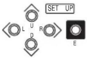
The pushbuttons and their markings at left are provided on the back of the camera.
Up Switch (U) Used to select SETUP items (up and down).
Down Switch (D)
Right Switch (R) Used to modify the settings.
Left Switch (L)
Enter Switch (E) Used to enter and quit the setup mode and to save the settings.
* To enter the setup mode, hold down the E button longer than 2 seconds.
5-3. Entering the setup mode and its basics
5-3-1. SETUP MENU (Main menu)

Hold down the E button longer than 2 seconds, and the menu at left appears onscreen. A highlighted item is now selected.
(1)CAMERA ID Up to 24 characters can be displayed onscreen.
(2)DAY/NIGHT The day (color) or night (B/W) mode is selected.
(3)LIGHT CONTROL The backlight compensation and spot photometry modes are selected. The wide dynamic level and DC type iris lens are adjusted.
(4)GAIN The gain control and electronic sensitivity up modes are selected.
The electronic sensitivity multiplying factor is also selected.
(5)WHITE BALANCE The white balance mode is selected. The manual white balance settings are made.
(6)SYNC The sync systems (INT and LL) are selected and set up.
(7)MENU LOCK The saved settings can be locked.
(8) SETUP The EXIT, CANCEL or RESET action is selected and executed.
① EXIT: Used to save the settings and to quit the menu.
② CANCEL: Used to return the settings to the previously saved ones.
③ RESET: Used to return the settings to the factory ones.
* New settings are not saved if EXIT is selected to quit the menu.
5-3-2. SPECIAL MENU

Highlight EXIT on the SETUP MENU screen. Hold down the L and R buttons together, and the screen at left appears onscreen.
(Page 1/2 shown at left)
(1) PAGE Selection of page 1/2 or 2/2.
(2) CHROMA Used to adjust the chroma level.
(3) DETAIL Used to adjust the details.
(4) SETUP Used to select the setup levels (0 IRE and 7.5 IRE).
(5) MONITOR Selection of monitor CRT or LCD
(6) RESOLUTION Used to select the NORMAL or HIGH resolution mode.
(7) DNR Switching on and off of noise reduction.
(8) VIDEO STANDARD Used to switch between the video signal systems (NTSC/PAL).
(9) COLOR BAR Used to turn on and off the color bars.
(10)PROGRES.SCAN Used to select the Interlace or Progressive mode.
(11) RS-485ID Used to preset an ID number (1 thru 207) for RS-485 communication.
(12) RET Used to go back to the main menu screen.
5-4. Setup procedures
5-4-1. CAMERA ID
(1) CAMERA ID ON/OFF setting Highlight CAMERA ID. Using the E, L or R button, access the ON/OFF setting. Decide the ON or OFF setting with the L or R button.
| SETUP MENU | |
| →CAMERA ID | OFF |
| DAY/NIGHT | AUTO |
| LIGHT CONTROL | |
| GAIN | |
| WHITE BALANCE | ATW |
| SYNC | INT |
| MENU LOCK | OFF |
| SETUP | EXIT |
(2) ID characters setting
Keep CAMERA ID highlighted and press the E button. The screen at right shows up.
① ID
Press the E button on ID, and the cursor appears. With the L or R button, select a character. Press the E button to save it, and the character box advances to the next one. To
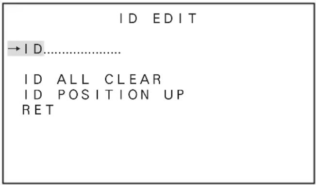
delete a character, press the E button to go through the code and place the cursor in the character to delete. Press the L or R button to get the box blank.
② ID ALL CLEAR
Highlight this item and press the E button. The ID code is cleared.
③ ID POSITION
Highlight this item and press the L or R button. In this way, the ID code can be positioned up or down.
④ RET
Press the E button to go back to the main menu screen.
5-4-2. DAY/NIGHT
(1) With the L and R buttons, make the AUTO, COLOR or B/W setting.
① AUTO
Automatic switching is made: high-quality color images during the day, and high-sensitivity monochrome pictures at night. Press the E button, and the screen at right shows up.
• B/W BURST
DAY/NIGHT AUTO
→B/W BURST ON
SWITCHED LEVEL DARK
LIGHT NORMAL
RET
The burst signal for black-and-white pictures can be selected ON or OFF.
- SWITCHED LEVEL
The brightness level for switching to the day or night mode can be preset. With the L and R buttons, the levels are selected in the order of BRIGHT, MID and DARK.
• LIGHT
Select “IR” when an infrared illumination or the like is used. Select “NORMAL” in other cases.
② COLOR
The color mode is fixed.
③ B/W
The black-and-white mode is fixed. Press the E button in this mode, and the menu opens up and the "B/W BURST" setting can be made like in ① above.
5-4-3. LIGHT CONTROL
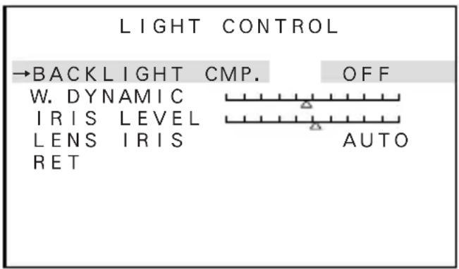
(1) Select LIGHT CONTROL on the main menu screen. Press the E button, and the screen at right shows up.
* The IRIS LEVEL item appears only when the lens selector switch at the camera's back is set at DC.
(2) BACKLIGHT CMP.
Highlight this item and the backlight compensation modes can be selected (ON, 1SPOT, 2SPOT and OFF).
① ON
Usual backlight compensation is made.
② 1SPOT
Select "ISPOT" and press the "E" button, and the screen shown at right appears. Highlight "ADJUST ZONE" and press the "E" button, and the photometric range setting screen shows up.
Each time the E button is pressed, the photometric frame color turns blue, green and red in this order.
- Blue Using the U, D, L or R button, the field can be moved wherever you like.
- Green Using the U, D, L or R button, the field can be enlarged.
- Red
Using the U, D, L or R button, the field can be reduced.


* To quit the field setting screen, hold down the E button longer than 2 seconds. Once the 1SPOT ZONE screen appears, select RET and press the E button. The previous menu shows up.
③ 2SPOT
As with the 1SPOT mode, two photometric fields can be preset. Take the same procedure as for the 1SPOT mode.
④ OFF
The backlight compensation function is off.
(3)W. DYNAMIC
The wide dynamic level can be varied with the L and R buttons. The intermediate level is initially set. In shooting scenes with greatly fluctuating light quantities, move the marker to the right to get a higher effect. Position the marker while watching an actual scene.
(4)IRIS LEVEL
This item appears when the DC type iris lens is in use. Move the marker to the right, and the lens aperture gets opener (Brightness enhanced). Position the marker while watching an actual scene.
(5)LENS IRIS
Select the lens' iris control system. (AUTO, MANUAL)
① AUTO
The automatic iris lens control function is enabled.
②MANUAL
This is selected with a manual iris lens in use. White saturation at high illumination is suppressed. In other words, too bright a subject can be reproduced rather clearly than usual.
(6)RET
Press the E button to go back to the main menu screen.
5-4-4. GAIN
(1)Select GAIN on the main menu screen. Press the E button, and the screen at right shows up.
(2)GAIN
With the L and R buttons, the gain control modes can be selected.
① AGC
This is an automatic sensitivity adjustment mode. Select AGC and press the E button, and maximum gain setting can be achieved. To suppress the noise lower than at the HIGH (initial) setting, select MID or LOW.
| GAIN | ||
| →GAIN | AGC | |
| SENS | UP | OFF |
| SLOW | SHUTTER | x 2 |
| RET | ||
② HYP-AGC
This mode is higher in sensitivity than AGC. But images may look rugged at higher sensitivities.
③ LOW : This fixed-gain mode keeps the sensitivity low for brighter spots.
④ MID : This fixed-gain mode keeps the sensitivity middle between HIGH and LOW.
⑤ HIGH : The fixed-gain mode keeps the sensitivity high for darker spots.
(3)SENS UP
The electronic sensitivity up modes can be selected with the L and R buttons. At all the positions but OFF, the automatic gain control function turns on itself.
The HYP-AGC mode can also be switched on.
① OFF (initial setting)
② S/N
The signal-to-noise ratio priority mode is used in shooting subjects that vary in brightness and move slightly.
③ STD
The standard mode is used in shooting subjects in brightness-changing spots to suppress both blurry images and rugged looks.
④ MOVE
The motion priority mode is used in shooting subjects that vary in brightness and move greatly like on the street and in parking lots.
* Note: With the sensitivity multiplying factor at maximum, the motion-dependent blurriness and ruggedness look the same in all the 3 modes.
* Note: In the S/N, STD or MOVE mode, the gain control levels LOW, MID and HIGH cannot be selected.
(4)SLOW SHUTTER
The electronic sensitivity multiplying factor can be adjusted with the L and R buttons. x2, x4, x8, x16, x32
The higher the factor, the higher the sensitivity, but motions at maximum factor look unnatural.
5-4-5. WHITE BALANCE
The white balance mode is selected. The manual white balance settings are made.
(1) The white balance modes can be switched with the L and R buttons.
① ATW (initial setting)
White balance is automatically followed up.
② ATW Ex
White balance is automatically followed up, but the color temperature range gets higher than the ATW mode. Compared with the ATW mode, color fading may be caused under usual light sources.
③ AWC
This is the so-called one-push automatic white balance control. Shoot a target white subject and press the E button, and the white balance will be adjusted.
④ MANUAL
Select MANUAL, press the E button and the screen at left appears onscreen.
R GAIN is used to adjust the reddish shades.
B GAIN is used to adjust the bluish shades.

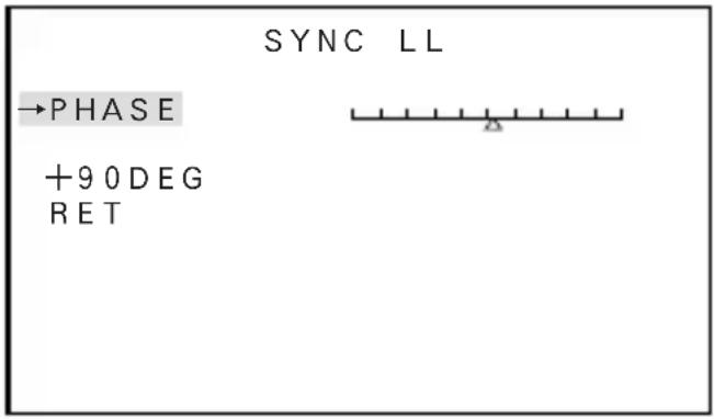
5-4-6. SYNC
(1) The INT and LL modes can be selected with the L and R buttons.
(2)INT
The internal sync mode is selected.
(3)LL
The line lock mode is selected. Press the E button, and the screen at right shows up.
① PHASE
With the L or R button, move the marker to finely adjust the phase.
② +90DEG
With the E button, the phase angle can be adjusted to 0° , 90° , 180° or 270° in the increment of 90° .
③ RET
Used to go back to the main menu screen.
5-4-7. MENU LOCK
The menu lock function protects saved settings against accidental modifications.
(1)Locking
Get the saved settings locked with the L and R buttons.
(2)Operation
When locked, EXIT alone is effective and all the other actions are inoperative.
(3) Unlocking
Press the U, R, D, L, U, D and E buttons in this order. If a wrong button is pressed halfway, start all over again.
5-4-8. SPECIAL MENU
(1) Highlight SETUP on the main menu screen and hold down the L and R buttons together. The SPECIAL MENU screen at right shows up.
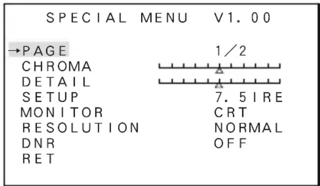
(2)PAGE
Pages can be selected with the "L" and "R" buttons.
| SPECIAL MENU | V1.00 |
| →PAGE | 2/2 |
| VIDEO STANDARD | |
| COLOR BAR | |
| PROGRES. SCAN | OFF |
| RS-485ID | 1 |
| RET |
(3)CHROMA
With the L and R buttons, the chroma level can be adjusted. Make the adjustment to your desired level while watching an image on screen.
(4)DETAIL
With the L and R buttons, the details can be adjusted. Make the adjustment to your taste while watching an image on screen.
(5)SETUP
With the L and R buttons, the setup level can be selected: 0 IRE and 7.5 IRE.
(6)MONITOR
The optimum picture quality can be selected according to the monitor used (CRT or LCD).
① CRT
Used when the camera is connected with a CRT (cathode ray tube) monitor.
② LCD
Used when the camera is connected with an LCD monitor.
(7)RESOLUTION
With the L and R buttons, the resolution can be selected.
• NORMAL
Natural-looking images are captured. (recommended)
• HIGH
High-resolution images are captured. They may look glaring depending on the types of subjects.
(8)DNR
The noise reduction function can be switched on and off.
(9)VIDEO STANDARD
The video signal systems (NTSC/PAL) are switched here. Select VIDEO STANDARD, press thee button and the warning screen at right shows up.
* Note: Select a video signal system according to your TV system. If the selection is wrong, no or distorted images may result. This does not mean the camera is in trouble.
① CANCEL
Used to go back to the SPECIAL MENU screen.
② OK
Used to go to the SELECT VIDEO STANDARD screen. (See at right.) Highlight VIDEO STANDARD. With the L or R button, the NTSC and PAL systems can be switched each other.


* Each time another system is selected, the current settings will be back to their factory.
Select RET, and the SPECIAL MENU screen reappears.
(10) COLOR BAR
Press the E button to get the color bars displayed. Press the E button again to go back to the SPECIAL MENU screen.
(11)PROGRES.SCAN
① OFF
Interlace mode output. Normal operation should be use at OFF.
② ON
Progressive scan mode output. When it connects to Frame Recording DVR, it should be use at ON. It will be reduced blurring of moving subject when it plays recorded images by DVR. However it will be shutter speed of 1/30 seconds, output video images from camera will be unnaturalness images with quick moving subject.
(12)RS-485ID
With the L and R buttons, an ID number (1 thru 207) can be preset.
(13)RET
Used to go back to the main menu screen.
5-4-9. Communication with control device (RS-485)
The camera can be controlled from a control terminal (PC, for example). For details, refer to the Communications Specifications.
6. Warranty and after-sale service
A warranty accompanies this product. Read and fill out the warranty card that you have received at your dealer. Keep this card in a safe place.
- Please consult Ikegami Electronics (U.S.A.) Inc. or Ikegami Electronics (Europe) GmbH or your dealer for full warranty information. Your dealer will repair or replace free of charge within the warranty period according to the warranty coverage.
- For repairs after the expiration of the warranty period, consult your dealer or sales representative. It will first be judged whether the trouble is repairable or not. Charged servicing will then be made upon request of the user.
- Before you ask for servicing, take trouble of reading the Instruction Manual. If the unit still fails, take note of the model number, date of purchase, problem, etc. in detail, and inform your dealer or sales representative.
- If you have questions about the after-sale service, contact your dealer or sales representative.
* We suggest you ask for preventive inspection earlier.
7. Specifications
(1) Imaging device: 1/3-inch DPS CMOS sensor
(2) No. of effective pixels: Approx. 390,000 pixels, 720(H) x 540 (V)
(3) Scanning system: NTSC: 525 TV lines/59.94 Hz (60 Hz with Line-Lock ON),
2 : 1 interlace
(4) Sync system: INT/LINE-LOCK (phase adjustable) (Line-lock not usable
where the power frequency and the camera's vertical frequency are different from each other or when the camera is DC-driven)
(5) Video output: VBS 1.0 Vp-p/75 ohms
(6) Resolution: Horizontal; 520 TV lines
(in high-resolution mode, at rated illumination)
(7) S/N ratio: Over 50 dB/rms (in normal mode, AGC OFF, Detail OFF
and Weighting ON )
(8) Minimum subject illumination: In color mode;
1.0 lux/F1.4 (video output 50%, HYPER-AGC)
In B/W mode;
0.2 lux/F1.4 (video output 50%, HYPER-AGC)
0.1 lux/F1.4 (video output 25%, HYPER-AGC)
(9) WDR function: Variable at 36 levels
(10) AGC: ON (AGC, HYPER-AGC)/OFF (LOW, MID, HIGH) selectable
(11) Electronic sensitivity up: Automatic (up to 32 times: interlocked with AGC mode)
(12) White balance: ATW/ATWex/AWC/MANU selectable
(13) Noise reduction: ON/OFF switchable
(14) Monitor selection: CRT/LCD switchable
(15) Day/night switching: Automatic/Manual switchable
(16) Auto iris function: Compatible with VIDEO iris and DC iris
(switchable, with DC iris level adjuster)
(17) Camera ID: Up to 24 characters (alphanumeric and symbols)
(18) Local setup: Selectable and adjustable with on-screen display using
pushbuttons; camera ID, AGC ON/OFF, ATW/AWC/MANU selection and adjustment, LL/INT switching, phase adjustment, wide dynamic range level, iris level, spot area setting, electronic sensitivity up ON/OFF, DNR ON/OFF, monitor selection CRT/LCD, detail level, chroma level, day/night mode switching and level
(19) Remote setup: Possible (control with RCU-701/RCU-801 or RS-485)
Same presettable items as with the local setup
(20) Lens mount: CS mount
(21) Flange focal distance Provided adjusting mechanism:
(22) Power supply: AC 24 V ±10%, 50/60 Hz, DC 12 V (10.5 – 15 V)
(23) Power consumption/current: AC 24 V; Approx. 280 mA DC 12 V; Approx. 275 mA
(24) Ambient operating temperature/humidity: -10 to +50°C, 30 to 90%RH (no dew condensation)
(25) Camera mount: 1/4" -20UNC (top and bottom mountable)
(26) Outer dimensions: 62(W) x 55(H) x 122(D) mm (no projections included)
(27) Weight: AC 24 V/DC12 V; Approx. 420 g
(28) Input/output connectors: • VIDEO OUT; BNC
- LENS; 4P (applicable plug E4-191J-150 or equivalent)
• DC 12V/AC 24V input; 2-pin terminal block
• RS-485 input/output; 5-pin terminal block
(29) Accessories: Instruction Manual, 1 copy
* Specifications and design are subject to change for product improvements without notice.
Highlight CAMERA ID. Using the E, L or R button, access the ON/OFF setting. Decide the ON or OFF setting with the L or R button.
| SETUP MENU | |
| →CAMERA ID | OFF |
| DAY/NIGHT | AUTO |
| LIGHT CONTROL | |
| GAIN | |
| WHITE BALANCE | ATW |
| SYNC | INT |
| MENU LOCK | OFF |
| SETUP | EXIT |
① CANCEL
37 Brook Avenue, Maywood, New Jersey 07607, U.S.A.
Phone: (201) 368-9171, FAX 201-569-1626
Ikegami Electronics (Europe) GmbH
Ikegami Strasse 1, 41460 Neuss 1, F.R. Germany
TEL. 02131-123-0/FAX 02131-102820
■ Ikegami Electronics (Europe) GmbH U.K. Branch
Unit E1 Cologne Court Brooklands Close,
Windmill Road Sunbury-on-Thames Middlesex TW16 7EB, UK
TEL. 01932-769700/FAX 01-92-769710
- Ikegami
- Contents
- NOTE:
- CAUTION;
- Instructions for Disposal of Electric and Electronic Equipment in Private Household
- Disposal of used Electric and Electronic Equipment
- (Applicable in the European Union and other European countries with separate collection systems)
- Handling precautions
- General
- Features
- Names of parts and their functions
- ① Lens mount (CS mount)
- ② Flange focal distance adjuster
- ③ Focus lock screw
- ④ Holder mounting screw holes
- Note
- ⑤ Lens selector switch
- ⑥ Auto iris lens connector
- - For the video type auto iris lens
- - For the DC type auto iris lens
- Operation
- 5-1. User setup
- 5-2. SETUP switches and their functions
- 5-3. Entering the setup mode and its basics
- 5-3-1. SETUP MENU (Main menu)
- 5-3-2. SPECIAL MENU
- 5-4. Setup procedures
- 5-4-1. CAMERA ID
- ID characters setting
- 5-4-2. DAY/NIGHT
- 5-4-3. LIGHT CONTROL
- (3)W. DYNAMIC
- (4)IRIS LEVEL
- (5)LENS IRIS
- 5-4-4. GAIN
- (3)SENS UP
- 5-4-5. WHITE BALANCE
- 5-4-6. SYNC
- 5-4-7. MENU LOCK
- 5-4-8. SPECIAL MENU
- (2)PAGE
- (3)CHROMA
- (4)DETAIL
- (5)SETUP
- (6)MONITOR
- (7)RESOLUTION
- (8)DNR
- (9)VIDEO STANDARD
- 5-4-9. Communication with control device (RS-485)
- Warranty and after-sale service
- Specifications
Brand : Ikegami
Model : ISD-A21
Category : Security Camera