High Performance IPD-DM100 - Security Camera Ikegami - Free user manual and instructions
Find the device manual for free High Performance IPD-DM100 Ikegami in PDF.

| Product Type | IP Network Dome Camera |
| Brand | Ikegami |
| Model | IPD-DM100 |
| Image Sensor | 1/3-type CMOS, approx. 1.4 megapixels (1329 x 1049) |
| Minimum Illumination (Color, Hyper-AGC, Sens Up Off) | 1.1 Lx (smoke dome), 0.55 Lx (clear dome) |
| Video Compression | H.264 and JPEG |
| Max Resolution | 1280 x 1024 |
| Frame Rate | Up to 30 fps |
| Day/Night Switching | Auto (with ACK), Manual (Color/B/W) |
| Built-in Lens | Varifocal, 3-axis adjustment, field angle 90.0° (W) to 31.8° (T) horizontal |
| Power Supply | DC12V (10.5-15V) / AC24V (±10%) / PoE (IEEE 802.3af Class 0) |
| Power Consumption | Approx. 7 W |
| Dimensions (Diameter x Height) | ø138 x 145 mm |
| Weight | 840 g |
| Operating Temperature | -10 to +50 °C |
| Operating Humidity | 30 to 90% RH (non-condensing) |
| Storage Media | MiniSD card (supports SDHC) |
| Audio | Built-in high-sensitivity internal microphone, ADPCM compression |
| Alarm I/O | 3 inputs/outputs (dry contact / open collector) |
| Security Features | Privacy mask (up to 8 zones), motion detection, camera ID, IP address filtering |
| Installation | Indoor use, ceiling or wall mount (may use trim ring) |
| Maintenance | Periodic checks recommended; clean dome cover gently with soft cloth |
| Warranty and Spare Parts | Contact dealer; performance parts available for 7 years after production stop |
Frequently Asked Questions - High Performance IPD-DM100 Ikegami
User questions about High Performance IPD-DM100 Ikegami
0 question about this device. Answer the ones you know or ask your own.
Ask a new question about this device
Download the instructions for your Security Camera in PDF format for free! Find your manual High Performance IPD-DM100 - Ikegami and take your electronic device back in hand. On this page are published all the documents necessary for the use of your device. High Performance IPD-DM100 by Ikegami.
USER MANUAL High Performance IPD-DM100 Ikegami
OUTDOOR USE WARNING
WARNING — TO PREVENT FIRE OR ELECTRIC SHOCK, DO NOT EXPOSE THIS APPLIANCE TO RAIN OR MOISTURE.
Ikegami
Ikegami Tsushinki Co., Ltd.
Thank you much for choosing this Ikegami mega-pixel IP netword dome camera. Please read this Instruction Manual carefully to keep your Ikegami camera at peak performance for longer service duration. All Ikegami cameras are designed and manufactured with utmost care and craftsmanship to provide long life and high quality performance, if it is properly used and maintained as outlined in this manual.
The Instruction Manuals for this device are composed of three sections: this manual, Installation Manual, and Instruction Manual (Application Instructions). This manual describes operation and settings of the device. Refer to the Installation Manual for installation and to the User's Manual for network connections and settings.
●The User's Manual can be downloaded here:
http://www.ikegami.co.jp/en/products/security/download/index.html
●Software for displays: A special viewer is required for displaying images via the network. Consult with your dealer on how to obtain a viewer.
This Ikegami product is made of ECO friendly components based upon the companies policy and corporate social responsibility to contribute towards the Global Environmental Solution for energy conservation and environmental sustainability, all the components used in this product are Non-hazardous, Non-Toxic, Lead-Free and conform with Japan's Green Product regulations(*), the EU's RoHS directive and other regulations and laws relating to Environmental and Hazardous Chemical Substances.
Contents of IPD-BX110 Instruction Manual
Page
- Introduction ...... 1
1-1. Handling precautions .... 1
1-2. Disclaimer 2
1-3. Protection of personal information 2
1-4. Cautions Concerning Network Connections .... 3
1-5. Limitations on Equipment Use 3
1-6. License for third party software 4
-
General 5
-
Features 5
-
Names of parts and their functions .... 7
4-1. Terminal Block 9
- Installation 11
5-1. Removing the dome cover 11
5-2. Attaching the dome cover 11
5-3. Attachment method when not using trimmed ring 12
5-4. Attachment method when using trimmed ring 14
- Setup 16
6-1. Setup Switches and functions 16
6-2. Setup 1 17
6-3. Setup 2 25
6-4. Setup 3 26
-
FOCUS EZ function 30
-
Troubleshooting 32
-
Warranty and after-sale service 33
-
Specifications 34
-
External Appearance 37

The exclamation point within an equilateral triangle is intended to alert the user to the presence of important operating and maintenance (servicing) instructions in the literature accompanying the appliance.
NOTE:
This equipment has been tested and found to comply with the limits for a Class B digital device, pursuant to Part 15 of the FCC Rules. These limits are designed to provide reasonable protection against harmful interference in a residential installation. This equipment generates, uses and can radiate radio frequency energy and, if not installed and used in accordance with the instructions, may cause harmful interference to radio communications. However, there is no guarantee that interference will not occur in a particular installation. If this equipment does cause harmful interference to radio or television reception, which can be determined by turning the equipment off and on, the user is encouraged to try to correct the interference by one or more of the following measures.
CAUTION;
ANY CHANGES OR MODIFICATIONS NOT EXPRESSLY APPROVED BY THE PART RESPONSIBLE FOR COMPLIANCE COULD VOID THE USERS AUTHORITY TO OPERATE THE EQUIPMENT.
Instructions for Disposal of Electrical and Electronic Equipment in Private Households

Disposal of used Electric and Electronic Equipment
(Applicable in the European Union and other European countries with waste recycling, disposal and collection regulations)
This symbol on the product, or in the related documents in the package, indicates that this product shall not be treated as normal household waste. Instead, it should be taken to a proper applicable collection point or depot for the recycling of electrical and electronic equipment.
By ensuring this product is disposed of correctly, you will help prevent possible negative consequences for the environment and human health which could otherwise caused by inappropriate handling of this product. The correct recycling of materials will help to conserve natural resources.
For more detailed information about recycling of this product, please contact your local city authority, your household waste disposal service or the place where you purchased the product.
1. Introduction
1-1. Handling precautions
- Do not install the camera in a water-splashed or highly humid environment.
- Do not use the camera where the ambient temperature drops below -10^ or rises above +50^ . The images and component parts may be adversely affected or the camera may not function correctly.
- When housing in a camera housing, pay attention to the temperature inside the housing. The temperature inside the housing becomes the camera ambient temperature.
- Never open the camera case because there are precision electrical and electronic components inside and an accident may result.
- Be sure to turn off the power before installing or making connections.
- Be careful not to drop or give a strong shock to the camera while transporting it.
- Do not insert hands or fingers in the interior of the lens mount.
- Do not orientate the camera directly towards the sun.
- In case of an auto-iris lens, the focus may be unstable (hunting) due to insufficient adjustment and lead to such phenomena as insufficient light. In such a case, carry out readjustment of the Iris Level with setup.
- To use the lens focus function in the ideal conditions, carry out adjustment of the flange focus (distance from the lens attachment surface to the surface to be photographed).
- T o obtain maximum benefits from the features of this product, use lenses especially designed for mega-pixel cameras.
- U se only the recommended SD card.
SD cards other than the recommended card may not operate normally or result in a reduction in performance.
* The recommended SD card is listed in the Application Section.
1-2. Disclaimer
(1) This equipment is used to take images as a surveillance camera. It is not to be used for the purpose of crime prevention.
(2) Ikegami assumes no responsibility for the following matters.
① System impediment, malfunction or breakdown as a result of connecting with equipment from other companies.
② Accidents or breakdowns due to mistaken usage or negligence.
③ Disassembly or repair of equipment that is not recognized by Ikegami.
④ Improper use by a third party of the surveillance images produced by this equipment, or damages resulting from such use.
⑤ Loss of the setting contents.
⑥ In addition, all damages resulting directly or indirectly in connection with this device.
(3) SD Card
- Please be aware that this company assumes no responsibility regarding guarantees in cases where images were not recorded due to problems with this device or the SD card.
-
The following cases may involve destruction (loss) of recorded data. Please be aware that this company cannot assume any responsibility regarding damages due to destruction of data.
-
Mistaken usage method of SD card.
- If the SD card was not correctly inserted in the device.
- If the SD card has undergone electrical or mechanical shock or force.
- If the SD card was removed or the device power was turned off during access to the SD card.
1-3. Protection of personal information
If it is possible to identify individuals with the image information obtained with this device, this amounts to personal information as determined in the Act on the Protection of Personal Information. Image information of this sort should be handled properly in accordance with the law.
The contents of information recorded on the SD memory card used with this device may correspond in some cases to private information. If this device is given to a third party due to disposal, transfer or repairs, please be especially careful about handling.
1-4. Cautions Concerning Network Connections
This equipment is connected to a network for use. To protect the system from damage unique to network connections, the customer should act on personal responsibility to carry out security measures.
Damage unique to networks includes leaking/outflow of information obtained with this device, damages due to illegal access and system stoppage.
Countermeasures include the following. The customer should additionally take personal responsibility to insure sufficient countermeasures.
- Do not install in locations where cables can be easily exchanged.
- Insure network security (firewalls, etc.)
- Carry out periodic virus checks on computers connected to the system.
- Computers connected to the system should have limitations on users (password setting).
- The system should be managed to insure that there is no leaking of authentication information.
1-5. Limitations on Equipment Use
This equipment has its usage regulated by the VC-1 and AVC/H.264 Patent Portfolio Licenses Concerning Personal and Non-Commercial Use. This license should be observed in limiting use of this equipment to private use or uses that are non-profit.
For details consult the following:
http://www.mpegla.com
Reference: Actions permitted by VC-1 and AVC/H.264 images for private and non-commercial uses.
(1) Only encoding of images to the VC-1 and AVC/H.264 for private uses or uses not having profit for purposes.
(2) To be used for encoding for private applications or applicant that do not have profit as a goal, and for decoding of VC-1 and AVC/H.264 images from a supplier who has obtained a patent.
1-6. License for third party software
We are licensed to use the software made by third parties for this product. The license for each software shall be applicable to the software in question respectively and not to the whole software of this product.
Certain software used in this product and made by third parties are used based on the following licenses:
* GNU General Public License Version 2 (GPL)
http://www.gnu.org/licenses/old-licenses/gpl-2.0.html
* GNU Lesser General Public License Version 2.1 (LGPL)
http://www.gnu.org/licenses/old-licenses/lgpl-2.1.html
* OpenSSL License
http://www.openssl.org/source/license.html
This product includes software developed by the OpenSSL Project
for use in the OpenSSL Toolkit. (http://www.openssl.org/)
* Original SSLeary License
http://www.openssl.org/source/license.html
This product includes cryptographic software written by Eric Young
(eay@cryptsoft.com)
The text of the license is included in the Instruction manual (Application Instructions).
Distribution of source code of free software
If you would like to purchase the GPL/LGPL software used in this product, please contact our sales division. In accordance with the licence terms, we will provide this at cost.
2. General
This equipment is a surveillance-use mega-pixel IP network dome camera featuring Web server functions for connection to a network.
The image compression makes use of the H.264 method to supply high-quality images. Because it is used with PoE, it is possible to connect it to an Ethernet to easily create a surveillance camera network system.
The camera section makes use of a 1.4 million pixel 1/3-type single plate CMOS sensor to offer high resolution, high sensitivity, and high picture quality in addition to backlight compensation and auto iris functions, etc. This is a CCTV camera suited to all general surveillance purposes.
The exterior makes use of a compact dome housing, making it ideal as an indoor surveillance camera with emphasis on interior qualities.
3. Features
(1) High picture quality, high resolution
Newly developed high sensitivity 1.4 million pixel 1/3-type CMOS RGB sensor and digital process circuit for high precision and azimuth and low noise to create sharply defined images.
(2) High image quality image compression
Features latest H.264 compression engine for delivery of high-quality images even at high compression rates.
(3) PoE, Power over Ethernet:
The PoE provision is built-in this unit, so that no need to apply an external power if there is no power outlet nearby. This provision makes this unit and associate system units useful to make an operationally effective system without power supply problems.
(4) Full range of image quality adjustment functions
Includes automatic-trace type white balance control (ATW), backlight compensation, flickerless function, etc. to match to the ideal image quality in a variety of scenes.
(5) Compact dome configuration
The camera and lens are housed in a stylish, compact dome configuration to allow surveillance with images but with no awareness that a camera is there.
(6) Varifocal lens integrated structure for adjustment on three axes.
Integrated design includes three-power varifocal lens.
Adjustment possible on three axes to allow adjustment to an arbitrary imaging range even when attached on a wall.
(7) FOCUS EZ function
Uses focus adjustment auxiliary function to confirm the focus condition with a focus indicator displayed on the screen.
When using the auto-iris lens, it is possible to forcibly open the lens focus for easy focus adjustment without worrying about the depth of field.
(8) Audio function
Features highly sensitive internal microphone for audio/video surveillance.
(9) Monitor-use analog image output (for image confirmation)
Features an analog image output for display on NTSC monitors, etc. This simplifies field angle adjustment during installation (the analog image output is only for field angle confirmation).
(10) Motion Detection Function
A motion detection function with Ikegami's original algorithms and resistant to reaction has been adopted for use outdoors, etc. for reduction in error detection caused by shaking leaves on trees, etc.
(11) Alarm Function
Equipped with a pre-alarm function to record images prior to generation of an alarm if an alarm is generated.
4. Names of parts and their functions
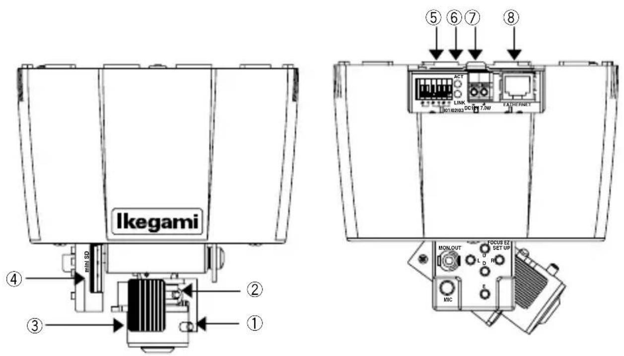
① Zoom ring retention screw
Screw for aligning zoom magnification and retaining it.
② Focus ring retention screw
Screw to align focus and retain it.
③ Angle adjustment clip
Clip that is held when attaching the monitor to ⑨ and carrying out field angle adjustment of image.
* Do not adjust while holding other sections.
④ MiniSD card slot
Insertion slot for miniSD card.
Compatible with SDHC.
⑤ Alarm input/output
Used for remote control of alarm input/output.
For details, see Section 4-1. Terminal Block.
⑥ LED
LINK Green lamp lights when connection with other instruments has been established.
ACT Orange lamp blinks during transfer and reception of data with other instruments.
⑦ DC12V/AC24V Input Connector
Power source input connector when not supplying power from PoE.
Input a power source of DC10.5V - 15V or AC24V±10%
* This installation should be made by a qualified service person and should conform to all local cades.
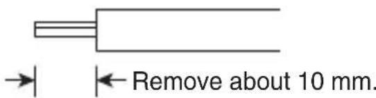
The thickness of the cable for connection is 0.4 - 1.2SQ (AWG24-12).
⑧ Ethernet connector (RJ45)
To be used with Ethernet 10Base-T/100Base-TX. For connection to other devices, use a cable of category 5 or higher.
Used with PoE (IEEE 802.3af) CLASS 0.
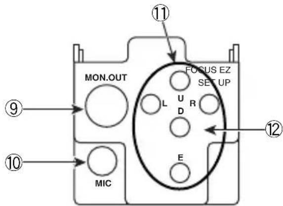
⑨ Monitor image output terminal (RCA pin jack)
Outputs analog images (NTSC) (terminate with 75Ω)
⑩ Internal microphone
High sensitivity microphone housed inside.
⑪ FOCUS EZ function switch
FOCUS EZ is a function that supports focus adjustment.
For details, see Section 7: FOCUS EZ Function.
⑫ Setup function switch
See Section 6: Setup
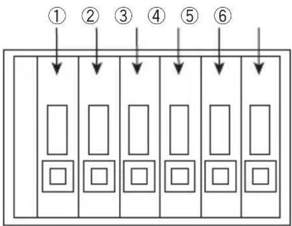
4-1. Terminal Block
These terminals are used as input or output terminals.
Only connect after first confirming that no power is being supplied to the equipment.
4-1-1. Terminals
flowchart
graph TD
    A["①"] --> B[" "]
    C["②"] --> D[" "]
    E["③"] --> F[" "]
    G["④"] --> H[" "]
    I["⑤"] --> J[" "]
    K["⑥"] --> L[" "]
| No. | Name Function | |
| 12 | IO1 Alarm input | output terminalNormally open no-voltage contact input or open collector output.Terminal 2 is grounded. |
| 34 | IO2 Same as | IO1.Terminal 4 is grounded. |
| 56 | IO3 Same as | IO1.Terminal 6 is grounded. |
4-1-2. When using as input terminal. (IO1/IO2/REMOTE)
■ Connection example
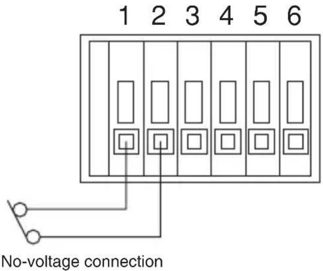
Operation
Operates with function set with input/output setting screen.
4-1-3. When using as output terminal. (IO1/IO2)
■ Connection example
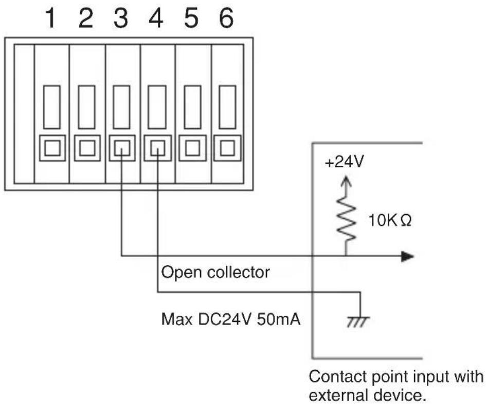
Operation
Operates with function set with input/output setting screen.
5. Installation
5-1. Removing the dome cover

Step 1: Turn the dome cover in the direction shown in ① (counterclockwise).
Step 2: While pressing down in the vicinity of catches B and D on the dome cover (or near A and C), lift up catches A and B to allow removal of dome cover.
5-2. Attaching the dome cover
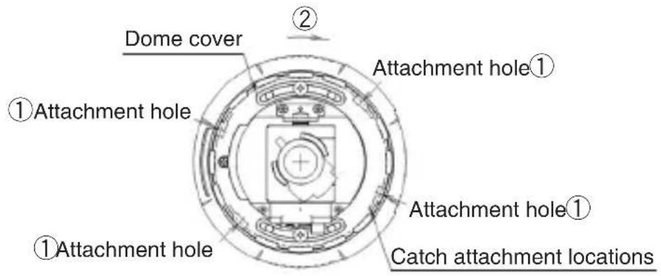
Step 1: Align the catches (4 locations) on the dome cover with the attachment holes ① on the main unit and then push down to attach the dome cover.
Step 2: Turn the dome cover in direction ② (clockwise) to attach the dome cover.
Note:
After attaching the dome cover, confirm that the catches have completely rotated to the catch attachment locations on the main unit.
5-3. Attachment method when not using trimmed ring
Attachment processing measurements chart
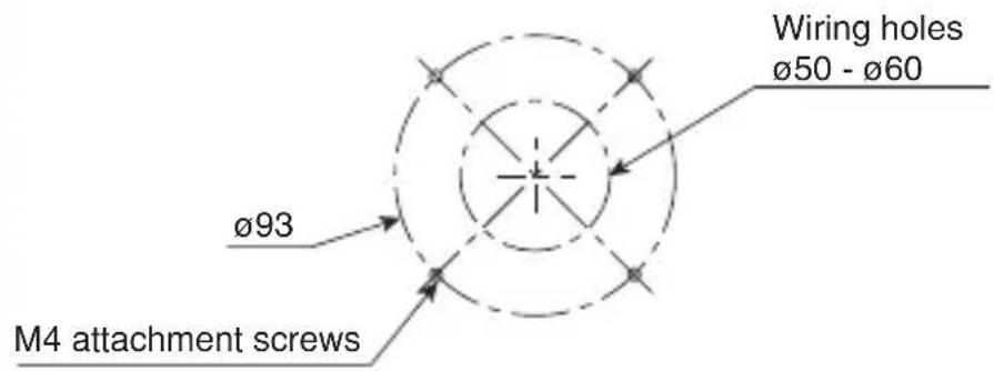
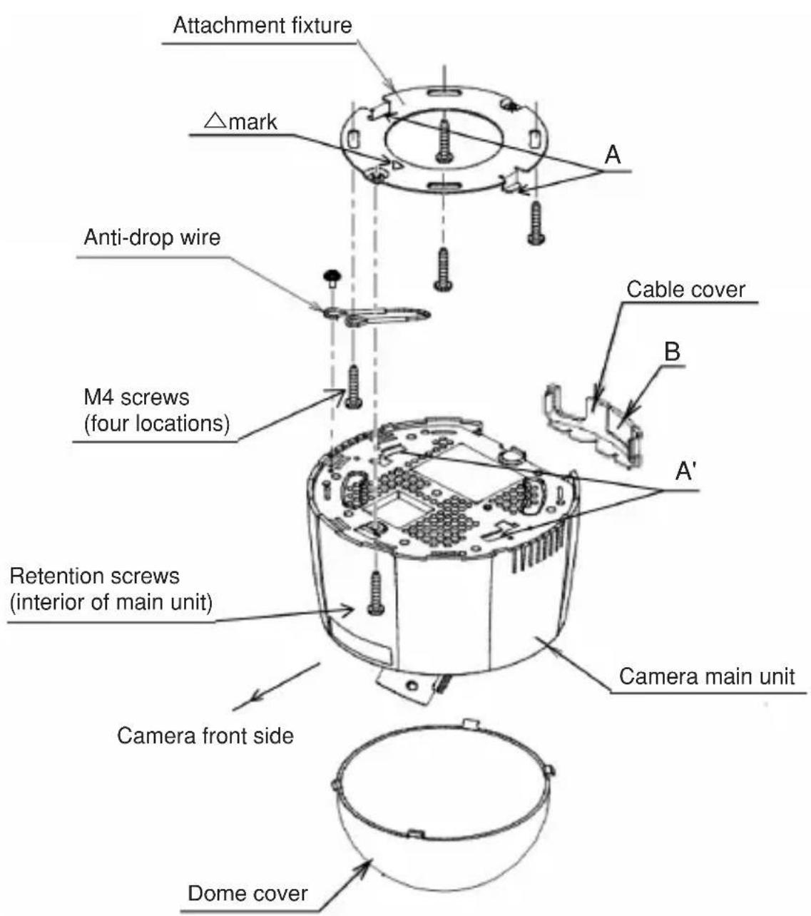
Step 1: Create a lower hole on the installation site for the M4 attachment screws. When necessary, create wiring holes (diameter: 50-60 mm).
Step 2: Following the steps in Section 5-1 (Removing the dome cover), remove the dome cover from the camera main unit.
Step 3: Attach the accessory attachment fixtures with the M4 screws. Also secure at this time together with the M4 screws the anti-drop wire in the position shown in the figure. The direction of the △ mark appearing on the attachment fixture should be the front when attaching the camera.
Step 4: Attach the anti-drop wire with a screw to the camera main unit side.
Step 5: Insert section A on the attachment fixture in holes A' (2 locations) on the camera main unit and turn the camera unit as far as possible in a counterclockwise direction.
Step 6: Use a screwdriver to tighten the retention screws on the camera main unit interior and attach the camera to the retention fixture.
Step 7: After lens adjustment and user setup, attach the dome cover in the order shown in Section 5-2 (Attaching the dome cover).
Notes
1) After installation, turn the dome cover in a clockwise direction and confirm that it is securely attached.
2) When attaching the cable, remove section B when necessary for use.
5-4. Attachment method when using trimmed ring
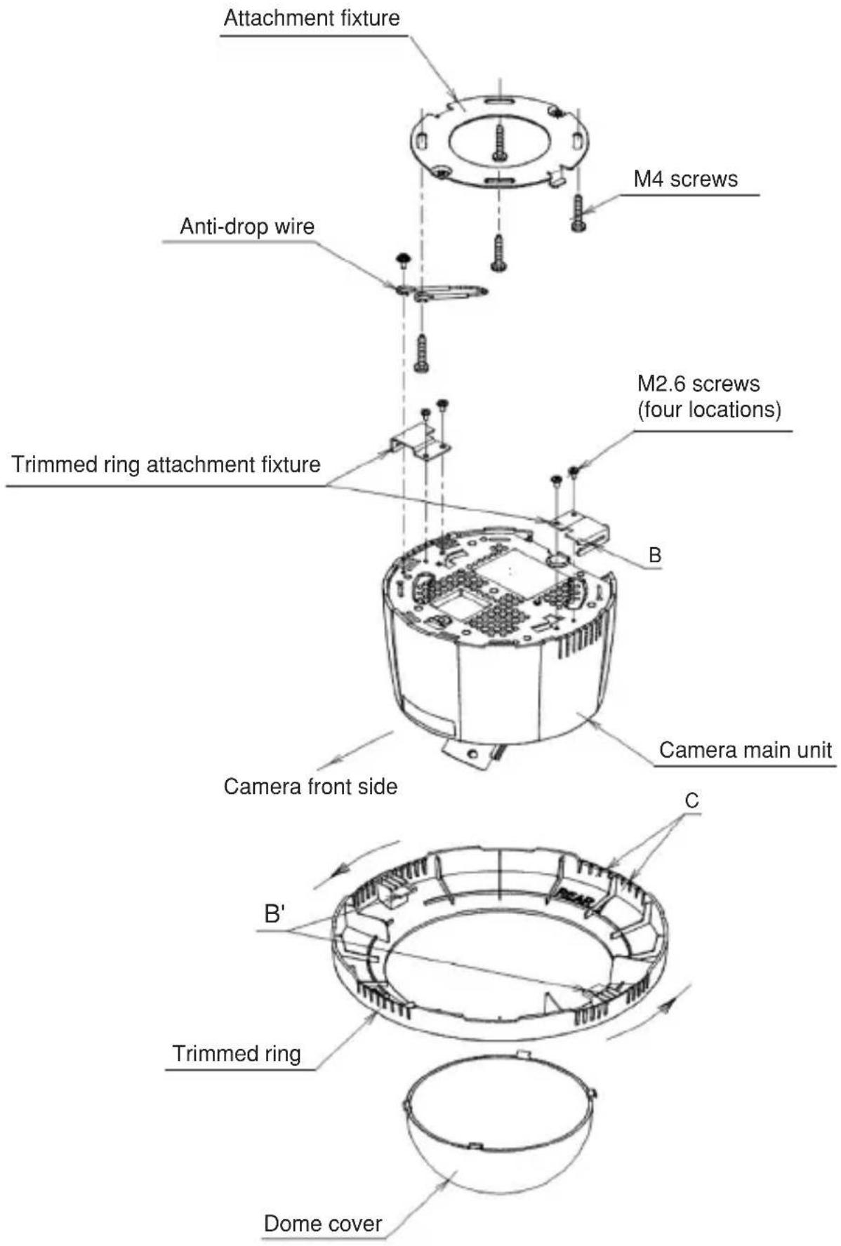
Step 1: When using the trimmed ring, use the screws to attach the trimmed ring attachment fixtures (2) to the main unit.
Step 2: Follow the same procedure as in steps 1-6 in Section 5-3 (Attachment method when not using trimmed ring) to attach the camera main unit to the attachment fixture.
Step 3: Rotate the trimmed rings so that slit B on the trimmed ring attachment fixture and slit B' on the trimmed ring match and then secure.
Step 4: After completing lens adjustment and user setup, follow the steps in Section 5-2 (Attaching the dome cover) to attach the dome cover.
Notes
1) After installation, turn the dome cover and the trimmed ring in a clockwise direction and confirm that they are securely attached.
2) When pulling the cable from the side of the trimmed ringg, first remove section C for use.
6. Setup
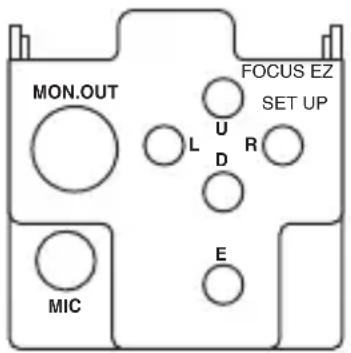
6-1. Setup Switches and functions
Setup involves making camera settings from the menu display on the screen.
Setup is controlled with the push switch on the back of the camera.
See Section 6-2 and the following sections regarding menus.

flowchart
graph TD
    A["FOCUS EZ"] --> B["SET UP"]
    B --> C["L U D R R E"]
    C --> D["SETUP MENU"]
    D --> E["PAGE 1/3"]
    E --> F["DAY/NIGHT OFF"]
    F --> G["SENS UP STD"]
    G --> H["SHUTTER X32 X1"]
    H --> I["LIGHT CONT. LENS. ."]
    I --> J["GAIN AGC"]
    J --> K["WHITE BAL. ATW1"]
    K --> L["MENU LOCK OFF"]
    L --> M["EXIT CANCEL RESET"]
    M --> N["Setting change [L"] button["R"] button]
    N --> O["Press [E"] button to go to submenu.]
| E | (Enter) | Press the button for 2 seconds to go to the set up mode. The setup menu is displayed on the screen.The setup mode is used to decide on and carry out settings and to move to the submenus. |
| U (Up) Select the menu item (up/down). | ||
| D (Down) | Also used for the FOCUS EZ ON(U) and OFF (D) functions. | |
| L (Left) Change setting values. | ||
| R (Right) | ||
* If a condition continues for more than 3 minutes with no switch operation, the system returns to the normal screen.
6-2. Setup 1
6-2-1. Main Menu 1/3
| SETUP MENU |
| PAGE 1/3DAY/NIGHT OFFSENS UP STDSHUTTER X32 X1LIGHT CONT. LENS..GAIN AGCWHITE BAL. ATW1MENU LOCK OFFEXIT CANCEL RESET |
(Condition on shipment from factory)
| PAGE Menu page number. Changes in order: 1/3, 2/3, 3/3. | |
| DAY/NIGHT AUTO Automatic switching to high quality color imagesACK function during the day and high-sensitivity black-white(Note 4) images at night. Press the [E] button to displaythe DAY/NIGHT submenu. Possible to set the brightness level for day or night.COLOR Color mode fixed.B/W Black/white mode fixed. | |
| SENS UP | If STD, MOVE, S/N mode has been selected, the GAIN automatically goes to AGC. It is also possible to switch to HYP-AGC.OFF There is no function for increasing the electronic sensitivity.S/N The S/N priority mode. Used to take pictures of objects for which the brightness changes and there is little movement.STD Standard mode. Used to take pictures at locations where the brightness changes and it is necessary to prevent object blurring and screen roughness.MOVE Mode giving priority to motion. Used to take pictures of images where brightness changes and there is movement, such as roads or parking lots, etc.MANUAL Setting of fixed magnification. The magnification can be set with the Shutter item. |
| SHUTTER If the electronic sensitivity increase mode is OFF (SENS UP = OFF), it is possible to select the high-speed shutter.If set to FL, flicker (resulting from fluorescent lamps, etc.) is eliminated.If the electronic sensitivity mode is ON (SENS UP = ON), it is possible to set the magnification for electronic sensitivity UP. | |
| LIGHT CONT. | If the [E] button is pressed, the submenu LIGHT CONTROL is displayed, and it is possible to adjust the auto-iris lens aperture and the backlight compensation (Note 1).For details, See Section 6-2-3. |
| GAIN Possible | to set image brightness.LOW Fixed sensitivity for bright locations.MID Fixed sensitivity between LOW and HIGH.HIGH Fixed setting for dark locations.AGC Standard automatic sensitivity adjustment.HYP-AGC High-sensitivity automatic sensitivity adjustment. |
| WHITE BAL. F | for adjusting difference in color tone due to light source differences (white balance).ATW1 Automatic tracking toward light source (Note 2).ATW2 Used when the color temperature adjustment range is wider than ATW1 and with a sodium lighting.AWC Automatic adjustmentFocus on the white object that is the target and press the [E] button.Before adjustment: AWC PUSH is displayed.During adjustment: AWC - - - - is displayed.When adjustment is finished:AWC SET is displayed.Following that: AWC PUSH is displayed.If AWC NG is displayed, see Note 3.MANUAL Press the [E] button to display the WHITE BALANCE submenu and carry out manual adjustment.For details, See Section 6-2-4. |
| MENU LOCK | Possible to prevent changes in settings in menu.Press the [E] button to set to ON. In the ON state, no controls other than EXIT are possible.To release: Press the buttons in the following order: [U] [R] [D] [L] [U] [D] [E] |
| Select the item with the [L], [R] buttons and then press the [E] button.EXIT Save the setting and return to the normal screen.CANCEL Return the setup to the final save state.RESET Return setup to the condition at time of factory shipment. | |
Note 1: For objects with a large light volume difference, the target object may be too dark and subdued (backlight condition). Backlight correction is the function used at this time to make the target object appear more brightly.
Note 2: For some objects, even if the white balance is set to ATW, tracking is not possible. In this case, carry out adjustment either with AWC or with MANUAL.
Note 3: For some objects, automatic adjustment (AWC) of white balance is not possible (AWC NG is displayed). In this case, carry out AWC again. If AWC NG appears again, carry out white balance adjustment with MANUAL.
Note 4: If the ACK (Automatic Chroma Killer) function is low illumination level, the system goes automatically to black-and-white images if the AGC gain increases. In addition, because the AGC gain is increased compared to color images, it is possible to use the camera as a high sensitivity camera.
6-2-2. Submenu [DAY/NIGHT] (AUTO)
| DAY/NIGHT | |
| SW LEVEL | MANUAL |
| COL→B/W | L··· |··· ·H |
| B/W→COL | L··· |··· ·H |
| RET | EXIT |
(Condition on shipment from factory)
| SW LEVEL Possible to set the day/night switching brightness level.The switching level becomes brighter in the order of DARK,MID, BRIGHT.If MANUAL is chosen and then press the [E] button, it ispossible to set the switching brightness. | |
| COL → B/W | Possible to set the brightness for changing from color to black/white. |
| B/W → COL | Possible to change the brightness for changing from black/white to color. |
| Select the item with the [L], [R] buttons and then press the [E]button.RET Returns to Main Menu (page 1/3).EXIT Save the setting and return to the normal screen. | |
6-2-3. Submenu [LIGHT CONTROL]
Backlight compensation OFF Backlight compensation ON
![Ikegami High Performance IPD-DM100 - 6-2-3. Submenu [LIGHT CONTROL] - 1](/content/2026/06/1148021/images/1c9304497674d65205a9064379ce31d90873399f8659252670aacaeac9704609.jpg)
flowchart
graph TD
    A["Light CONTROL"] --> B["BACKLIGHT CMP. OFF"]
    B --> C["IRIS LEVEL *L··· |···H"]
    C --> D["RET EXIT"]
    E["Light CONTROL"] --> F["BACKLIGHT CMP. ON"]
    F --> G["BLC LEVEL L··· |···H"]
    G --> H["IRIS LEVEL L··· |···H"]
    H --> I["RET EXIT"]
    J["Condition on shipment from factory"] --> K["Backlight compensation SPOT"]
    K --> L["Light CONTROL"]
    L --> M["BACKLIGHT CMP. SPOT"]
    M --> N["BLC LEVEL L··· |···H"]
    N --> O["IRIS LEVEL L··· |···H"]
    O --> P["RET EXIT"]
| BACKLIGHT CMP. | If set to ON or SPOT, the backlight compensation function is operating.The SPOT setting is used to optimize the brightness of the image for the indicated range. See Section 6-2-4 for setting methods.If backlight compensation is functioning, the item BLC (BACKLIGHT CMP.) LEVEL appears in the screen. |
| IRIS LEVEL Di | displayed when the auto-iris lens is being used.Used to adjust the lens aperture.The aperture opens in direction H to produce a bright image. |
| BLC LEVEL Used to adjust the effect of backlight compensation. The effect becomes large in direction H.Adjust according to the purpose. | |
| Select the item with the [L], [R] buttons and then press the [E] button.RET Returns to Main Menu (page 1/3).EXIT Save the setting and return to the normal screen. | |
6-2-4. Submenu [SPOT SET]
![Ikegami High Performance IPD-DM100 - 6-2-4. Submenu [SPOT SET] - 1](/content/2026/06/1148021/images/4986dbe3bc762b30a63e26a5b5c83f8787f2caf0ebbf63cdbc4f2ea1971724ce.jpg)
flowchart
graph TD
    A["Initial condition"] --> B["Setting range"]
    B --> C["Left end adjustment of setting range (example)."]
    C --> D["SPOT SETSPOT SET"]
    style A fill:#f9f,stroke:#333
    style B fill:#ccf,stroke:#333
    style C fill:#cfc,stroke:#333
    style D fill:#fcc,stroke:#333
    note right of B: Setting range becomes wider.
    note right of C: Left end adjustment of setting range (example).
| [Setting order] | 1 Use the [U], [D], [L] and [R] buttons to select the setting direction (blinking display).2 After determining the direction, press the [E] button (inverted blinking display).3 Use the [U], [D] buttons for adjusting the setting range in an up-down direction and the [L], [R] buttons for adjustment to the left and right.4 Press the [E] button. |
| RET | Returns to LIGHT CONTROL submenu. |
6-2-5. Submenu [WHITE BALANCE]
| R GAIN Carries out adjustment only of red. | |
| B GAIN Carries out adjustment only of blue. | |
| Select the item with the [L], [R] buttons and then press the [E] button.RET Returns to Main Menu (page 1/3).EXIT Save the setting and return to the normal screen. | |
6-3. Setup 2
6-3-1. Main Menu 2/3
| PAGE Menu page number. Changes in order: 1/3, 2/3, 3/3. | |
| CHROMA Possible to adjust contrasting density of image color. Color becomes denser in direction H. | |
| DETAIL Possible to adjust amount of image edge enhancement. Image becomes sharper in direction H. | |
| PEDESTAL Possible to adjust brightness of dark (low brightness) section of image. Image becomes brighter in direction H. | |
| VIDEO LEVEL Possible to adjust brightness of bright section of image. Image becomes brighter in direction H. | |
| EXIT CANCEL RESET Save the setting and return to the normal screen. Return the setup to the final save state. Return setup to the condition at time of factory shipment. |
6-4. Setup 3
6-4-1. Main Menu 3/3
| SETUP MENU |
| PAGE 3/3IP ADDRESS ENTER..CAMERA ID OFFPRIVACY MASK OFF |
| EIXT CANCEL RESET |
(Condition on shipment from factory)
| PAGE Menu page number. Changes in order: 1/3, 2/3, 3/3. | |
| IP ADDRESS | Press the [E] button to display the IP ADDRESS submenu.For details, See Section 6-4-2. |
| CAMERA ID If set to ON, the camera ID (character display on screen) becomes activated.If the [E] button is pressed, the ID EDIT submenu is displayed.It is possible to set the characters to be displayed (max. 24 characters).For details, See Section 6-4-3. | |
| PRIVACY MASK | Possible to set the privacy mask.Press the [L], [R] buttons to switch ON/OFF. When ON, press the [E] button to enter the privacy mask (hereinafter: mask) setting mode.For details, See Section 6-4-4. |
| EXIT CANCEL RESET | Select the item with the [L], [R] buttons and then press the [E] button.Save the setting and return to the normal screen.Return the setup to the final save state.Return setup to the condition at time of factory shipment. |
6-4-2. Submenu [IP ADDRESS]
IP ADDRESS
IP ADDRESS
-
-
- 100
-
SUBNET MASK
-
-
- 000
-
RET
EXIT
(Condition on shipment from factory)
| IP ADDRESSSUBNET MASK | Press the [U]/[D] buttons to select the address.192.168.001.100←[U] button [D] button →Moving to ID ADDRESS and SUBNET MASK is also done with the [U]/[D] buttons. |
| The [L]/[R/ buttons are used to change the address value.Press [R] to increase the value.Press [L] to decrease the value. | |
| RETEXIT | Press the [L], [R] buttons to select the item and then press the [E] button.Returns to Main Menu (page 3/3).Save the setting and return to the normal screen.If RET/EXIT are selected when the IP address has been changed, a message appears on the screen to remind the user to confirm.Do you changethe IP ADDRESS ?OK CANCELIf it is OK to change, select OK. To cancel select CANCEL and then press the [E] button. |
6-4-3. Submenu [ID EDIT]
![ID EDIT ABCDEFGHIJKLMNOPQRSTUVWXYZ↑ ↗→↘↓↙← 0123456789 :+-*/. . ID→ SPACE CLEAR RET EXIT POS Characters that can be used. Move with [U][D] buttons. Operation](/content/2026/06/1148021/images/d9127c46559666107857770d5db2d3b791221481e4d35d2dfc770bba6ad902f0.jpg)
| ← → | Determine the ID display start position.Use the [L], [R] buttons to move 1 character to the left or right. (Character selection).Use the [U], [D], [L], [R] buttons to select characters and then press the [E] button. |
| SPACE Press | the [E] button to enter a space. |
| CLEAR Use the [E] button to erase the ID that was set. | |
| RET EXIT POS | Select the item with the [L], [R] buttons and then press the [E] button.Returns to Main Menu (page 3/3).Save the setting and return to the normal screen.Moves to ID display position setting screen.ID display position setting screen[Possible to move _CAMERA ID within a determined range at the top of the screen by using the [U],[D],[L],[R] buttons. Press the [E] button to return to the ID EDIT screen. |
6-4-4. Submenu [PRIVACY MASK]
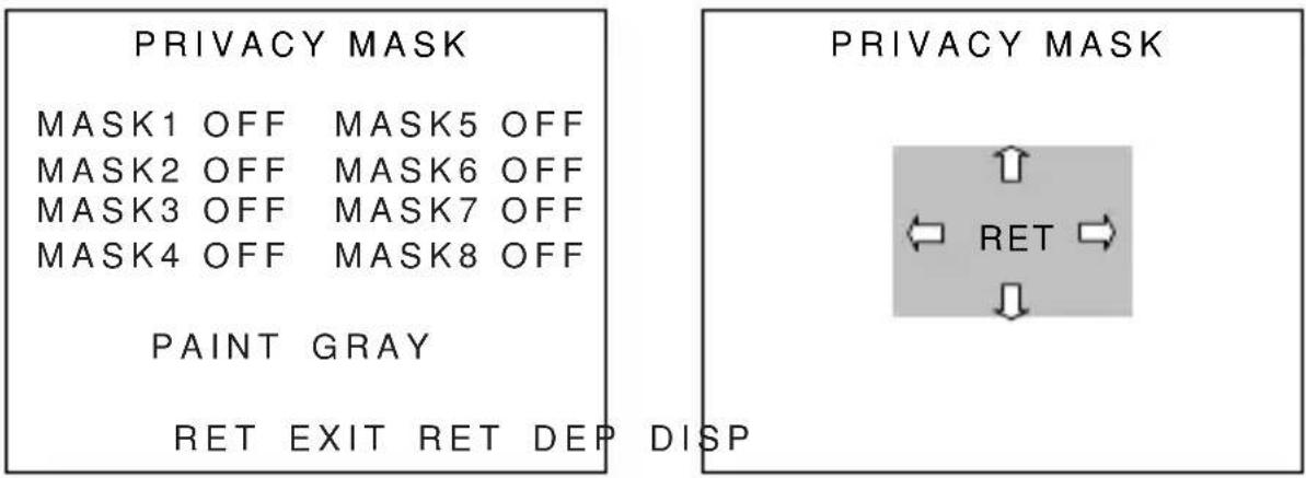
| MASK Possible to set up to 8 masks.Use the [U], [D] buttons to select the mask for setting and then use the [L]. [R] buttons to switch ON or OFF.If set to ON and the [E] button is pressed, domain setting is possible. | |
| PAINT Use the [L], [R] buttons to set the mask color.(BLACK, WHITE, GRAY, MOSAIC) | |
| [Setting order] | 1 Use the [U], [D], [L], [R] buttons to set the domain.Move the cursor near the arrow and press the [U] [D] buttons for above and below and the [L], [R] buttons for left and right to change the domain.2 Move the cursor to MOV and press the [E] button to move the entire mask. After deciding on movement, press the [E] button to return to the mask domain setting screen. |
| DEF Carry out | initialization of mask size and position. |
| DISP Displays | the mask for which setting is finished. |
| Select the item with the [L], [R] buttons and then press the [E] button.RET Returns to Main Menu (page 3/3).EXIT Save the setting and return to the normal screen. | |
![Ikegami High Performance IPD-DM100 - 6-4-4. Submenu [PRIVACY MASK] - 2](/content/2026/06/1148021/images/dc63880cbc3f886e504abf877e18584ff1259ae455b11256199a1c31b0ead89a.jpg)
7. FOCUS EZ function
FOCUS EZ is a function to support focus adjustment. A focus indicator displayed on the screen can be used to confirm the focus conditions. In case of auto-iris, it is possible to open the lens aperture forcibly for a set time period to carry out focus adjustment without worrying about field of depth even in a bright environment during the day. (The camera sensitivity is adjusted automatically, and there is no influence on the displayed image).
Press the FOCUS EZ (U) button for two seconds to start FOCUS EZ and go to the focus adjustment screen.
FOCUS EZ cannot be started in the setup mode.

After starting FOCUS EZ, the function continues for 1 minute. After that, by pushing the FOCUS EZ [U] button briefly it is possible to extend the period for 30 seconds.
While viewing the focus indicator on the focus adjustment screen, it is possible to adjust the focus. Displayed on the focus indicator are the focus ideal point (blue) and the present focus condition (light blue). Adjust the focus so that the focus condition reaches the ideal point.
Pressing the [D] button once during FOCUS EZ operation terminates FOCUS EZ (automatic release with time elapse, so there is no worry about forgetting to return after operations).
Note
There are delays in image distribution with Ethernet. When adjusting the focus, we recommend monitoring with the VIDEO OUT analog image. In the following cases, the focus indicator does not obtain sufficient accuracy.
- Movement • Unstable illumination
- Even surface such as solid color wall.
- Dark • Extremely bright
- Few lines in vertical direction. • Lens is dirty.
8. Troubleshooting
In case of possible malfunction, carry out the following checks according to the symptoms. If the symptoms do not disappear or in case of other symptoms, consult with your dealer.
| Problem | Check Point |
| The image doesn’t show up. | Are the IP address and subnet mask correct? |
| Power supply by PoE | |
| Are the HUB (and the port you are using) available for PoE? | |
| Is the HUB powered on? | |
| Is the LAN cable connected firmly? | |
| Power supply | |
| Is the power-supply voltage DC10.5 to 15V or AC24V±10%? | |
| Is the handling at the end of the power cable correct? | |
| Is the diameter of the power cable between 0.2 and 1.0SQ (AWG24 - 18)? | |
| The image is blurred. | Please check as described in “7. FOCUS EZ Function” and “Note” and re-adjust focus. |
| Is the lens dirty? | |
| The image is bright/dark | Please adjust the aperture of the lens. |
| Isn’t there a bright portion in the shooting area? Please setup BACKLIGHT CMP. (6-2-3). | |
| The setting can’t be changed. | Is the MENU LOCK (6-2-1) ON? |
9. Warranty and after-sale service
The Guarantee for this product is attached to this manual. Read the contents carefully and fill in the required items. Keep the Guarantee in a safe place.
- Please consult Ikegami Electronics (U.S.A.) Inc. or Ikegami Electronics (Europe) GmbH or your dealer for full warranty information. Your dealer will repair or replace free of charge within the warranty period according to the warranty coverage.
- For repairs after the expiration of the warranty period, consult your dealer or sales representative. It will first be judged whether the fault is repairable or not. Charged servicing will then be made upon request of the user.
- Before you ask for servicing, please ensure you read the Instruction Manual. If the unit still fails, take note of the model number, date of purchase, problem, etc. in detail, and inform your dealer or sales representative.
- For long use of this equipment, we recommend regular maintenance and checks. Consult with your dealer or sales representative.
- If you have questions about the after-sale service, contact your dealer or sales representative.
Holding period of performance parts requiring maintenance. Ikegami holds performance parts requiring maintenance for 7 years following production stop.
* Performance parts means parts required for maintaining the function of the product.
10. Specifications
(1) Image Sensor 1/3 type, CMOS sensor
Effective pixel count 1329(H) x 1049(V),
Approx. 1,400,000 pixels
Color filter: RGB method
(2) Scanning system Progressive scan
(3) Sync system Internal synchronization: Crystal-lock
(4) MONITOR OUT VBS 1.0Vp-p/75Ω (Field angle
adjustment: NTSC compliant)
(5) Minimum object illumination In case of smoke dome (standard)
1.1Lx (HYPER-AGC, Output 50%, Electronic sensitivity increase OFF, Color)
0.035Lx (HYPER-AGC, Output 50%,
Electronic sensitivity increase 32 power, Color)
0.017Lx (HYPER-AGC, Output 50%,
Electronic sensitivity increase 32 power, B/W)
In case of clear dome (optional)
0.55Lx (HYPER-AGC, Output 50%,
Electronic sensitivity increase OFF, Color)
0.017Lx (HYPER-AGC, Output 50%,
Electronic sensitivity increase 32 power, Color)
0.008Lx (HYPER-AGC, Output 50%,
Electronic sensitivity increase 32 power, B/W)
(6) Electronic sensitivity up Up to 32 times
Automatic (S/N, STD, MOVE)/MANUAL selectable
(7) Day/night switching With ACK function, Automatic/MANUAL
selectable
(8) AGC ON (AGC,HYPER-AGC)/
OFF (LOW,MID,HIGH) selectable
(9) White balance ATW1/ATW2/AWC/MANUAL
(10) Details correction Provided (Level adjustment possible)
(11) AES ON/OFF selectable (Cannot be used in
areas where the power source frequency is 50 Hz)
(12) Auto iris function Compatible with DC iris
(13) Electronic Shutter 1/30 (OFF) to 1/30,000, FL (Flickerless) Variable setting possible
(14) Back Light Compensation Provided (OFF/ON/SPOT, Level function adjustment possible)
(15) Focus assist FOCUS EZ function (With focus indicator)
(16) Built-in lens
- focal distance/maximum focal ratio
- Angle of field
| Zoom position hor | zontal vertical field angle field angle | |
| Wide terminal 90.0° | 66.2° | |
| Telephoto terminal | 31.8° | 23.9° |
- Angle adjustment Rotation 0^ - 360^
(during attachment), ±30^ (fine adjustment)
Lens up/down ±80° Lens rotation ±90°
(17) Privacy masking function
(18) Motion detection function
(19) Camera ID function
(20) Camera setup
Provided (Possible to set in max. 8 locations)
Provided (Mask setting possible)
Provided (1 line, max. 24 characters)
Possible
Switch operation with menu screen or remote control from client PC.
(21) Video compression system
(22) Image setting
- Compression system
- Image size
- Frame rate
- Bit rate (H.264 only)
• Picture Quality (JPEG only) - Transfer mode
(23) Audio function
(24) Audio compression system
(25) Image storage function
(26) Alarm input/output
(27) Network
H.264 and JPEG
3 pattern settings possible
H.264 or JPEG
1280 x 1024/640 x 480
7 levels (Maximum 30 fps)
512kbps to 8Mbps
5 levels
VBR/CBR
Provided (Internal microphone)
ADPCM 32kbps
Can be stored on SD memory card
Input: Dry contact (100 mS or higher)
Output: Open collector (Max. 24V 50 mA)
Ethernet 10Base-T/100Base-TX
(28) Protocol IPv4 :
TCP, UDP, RTP/RTCP, RTSP,
HTTP, FTP, NTP
Multicast possible
IPv6 : TCP, UDP, RTP/RTCP, RTSP,
HTTP, FTP
Multicast possible
(29) Monitoring Special viewer software or Special
recorder (HVR)
(30) Power Requirement DC12V (10.5V to 15V)/AC24V±10%
PoE (IEEE 802.3af) CLASS 0
(31) Power consumption/current Approx. 7 watts
(32) Operating temperature and -10 to +50°C/Within +30 to +90%RH
relative humidity (No Condensation)
(33) Dome cover Smoke type (clear type optional)
(34) Outer dimensions ø138 x H 145 mm
(35) Weight 840g
(36) Input/output connectors • LAN :RJ-45(Auto-MDI/MDIX)
- DC12V/AC24V input
:2P push-in terminal
- Alarm input/output
:6P push-in terminal
• MONITOR OUT
:pin jack (in dome)
- miniSD memory card slot
:Full size
(37) Accessories
Installation Procedure, Instruction Manual
* Specifications and design are subject to change for product improvements without notice.
11. External Appearance

Ikegami
■ Ikegami Electronics (U.S.A.), Inc.
37 Brook Avenue, Maywood, N.J. 07607, U.S.A.
Phone: (201) 368-9171, FAX (201) 569-1626
www.lkegami.com
or
■ Ikegami Electronics (U.S.A.), Inc, West Coast Office
2631 Manhattan Beach Blvd., Redondo Beach, C.A. 90278
Phone: (310) 297-1900, FAX (310) 536-9550
www.lkegami.com
■ Ikegami Electronics (Europe) GmbH
Ikegami Strasse 1, D-41460 Neuss, Germany
Phone : 02131-123-0, FAX 02131-102820
www.lkegami.de
■ Ikegami Electronics U.K. Office:
Unit E1, Cologne Court, Brooklands Close,
Windmill Road, Sunbury-on-Thames,
Middlesex, TW16 7EB, U.K.
Phone:01932-769700 FAX 01-92-769710
www.lkegami.co.uk

- Ikegami
- Contents of IPD-BX110 Instruction Manual
- NOTE:
- CAUTION;
- Instructions for Disposal of Electrical and Electronic Equipment in Private Households
- Disposal of used Electric and Electronic Equipment
- Introduction
- 1-1. Handling precautions
- 1-2. Disclaimer
- 1-3. Protection of personal information
- 1-4. Cautions Concerning Network Connections
- 1-5. Limitations on Equipment Use
- 1-6. License for third party software
- Distribution of source code of free software
- General
- Features
- Names of parts and their functions
- ⑦ DC12V/AC24V Input Connector
- ⑧ Ethernet connector (RJ45)
- ⑨ Monitor image output terminal (RCA pin jack)
- ⑩ Internal microphone
- ⑪ FOCUS EZ function switch
- ⑫ Setup function switch
- 4-1. Terminal Block
- 4-1-1. Terminals
- 4-1-2. When using as input terminal. (IO1/IO2/REMOTE)
- ■ Connection example
- Operation
- 4-1-3. When using as output terminal. (IO1/IO2)
- Installation
- 5-1. Removing the dome cover
- 5-2. Attaching the dome cover
- 5-3. Attachment method when not using trimmed ring
- Notes
- Setup
- 6-1. Setup Switches and functions
- 6-2. Setup 1
- 6-2-1. Main Menu 1/3
- 6-2-2. Submenu [DAY/NIGHT] (AUTO)
- 6-2-3. Submenu [LIGHT CONTROL]
- 6-2-4. Submenu [SPOT SET]
- 6-2-5. Submenu [WHITE BALANCE]
- 6-3. Setup 2
- 6-3-1. Main Menu 2/3
- 6-4. Setup 3
- 6-4-1. Main Menu 3/3
- 6-4-2. Submenu [IP ADDRESS]
- 6-4-4. Submenu [PRIVACY MASK]
- FOCUS EZ function
- Note
- Troubleshooting
- Warranty and after-sale service
- Specifications
- External Appearance
Brand : Ikegami
Model : High Performance IPD-DM100
Category : Security Camera