
Performance HD273XD2 - Security Camera HONEYWELL - Free user manual and instructions
Find the device manual for free Performance HD273XD2 HONEYWELL in PDF.

| Product Type | Security Camera (Bullet) |
| Resolution | 1080p (Full HD) |
| Image Sensor | 2 MP CMOS |
| Lens Type | 2.8mm Fixed Lens |
| Field of View | 90° |
| Night Vision | IR LEDs up to 30m |
| Power Supply | 12V DC or PoE (IEEE 802.3af) |
| Power Consumption | 6W max |
| Dimensions (W x H x D) | 70 x 60 x 120 mm |
| Weight | 0.4 kg |
| Protection Rating | IP66 |
| Mounting | Wall mount bracket included |
| Video Compression | H.264 |
| Frame Rate | 30 fps at 1080p |
| Audio | No built-in microphone |
| Storage | NVR or microSD card (not included) |
| Operating Temperature | -20°C to 50°C |
| Connections | BNC, RJ45, power input |
| Installation | Indoor/Outdoor use |
| Maintenance | Clean lens with soft dry cloth; check cables periodically |
| Safety | Disconnect power before cleaning; use only supplied power adapter |
| Spare Parts & Repairability | Contact Honeywell support for replacements; not user-serviceable |
Frequently Asked Questions - Performance HD273XD2 HONEYWELL
User questions about Performance HD273XD2 HONEYWELL
0 question about this device. Answer the ones you know or ask your own.
Ask a new question about this device
Download the instructions for your Security Camera in PDF format for free! Find your manual Performance HD273XD2 - HONEYWELL and take your electronic device back in hand. On this page are published all the documents necessary for the use of your device. Performance HD273XD2 by HONEYWELL.
USER MANUAL Performance HD273XD2 HONEYWELL
natural_image
Close-up of a Honeywell security camera with visible lens and control buttons (no text or symbols on the device itself)Performance Series
HD273XD2
1080P HQA Rugged Dome Camera
User Guide
Thank you for purchasing our product. If there are any questions, or requests, please do not hesitate to contact the dealer.
The information in this publication is believed to be accurate in all respects. However, Honeywell cannot assume responsibility for any consequences resulting from the use thereof. The information contained herein is subject to change without notice. Revisions or new editions to this publication may be issued to incorporate such changes.
Regulatory Information FCC compliance
This equipment has been tested and found to comply with the limits for a Class A digital device, pursuant to part 15 of the FCC Rules. These limits are designed to provide reasonable protection against harmful interference when the equipment is operated in a commercial environment. This equipment generates, uses, and can radiate radio frequency energy and, if not installed and used in accordance with the instruction manual, may cause harmful interference to radio communications. Operation of this equipment in a residential area is likely to cause harmful interference in which case the user will be required to correct the interference at his own expense.
Changes or modifications not expressly approved by the party responsible for compliance could void the user's authority to operate the equipment.
This Class A digital apparatus complies with Canadian ICES-003.
Manufacturer's Declaration of Conformance
North America The equipment supplied with this guide conforms to UL 60950-1 and CSA C22.2 No. 60950-1.
Europe The manufacturer declares that the equipment supplied is compliant with the European Parliament and Council Directive on the restriction of the use of certain hazardous substances in electrical and electronic equipment (2011/65/EU), General Product Safety Directive (2001/95/EC), and the essential requirements of the EMC directive (2014/30/EU), conforming to the requirements of standards EN 55032 for emissions, EN 50130-4 for immunity, and EN 62368-1 for electrical equipment safety.
CAUTION This is a Class A product. In a domestic environment, this product may cause radio interference in which case the user may be required to take adequate measures.
WEEE (Waste Electrical and Electronic Equipment)
Correct disposal of this product (applicable in the European Union and other European countries with separate collection systems). This product should be disposed of, at the end of its useful life, as per applicable local laws, regulations, and procedures.
Safety Instructions
These instructions are intended to ensure that users can use the product correctly to avoid danger or property loss.
The precautions are divided into "Warnings" and "Cautions".
Warnings: Serious injury or death may occur if any of the warnings are neglected.
Cautions: Injury or equipment damage may occur if any of the cautions are neglected.
| CAUTIONRISK OF ELECTRICSHOCKDO NOT OPEN | THIS SYMBOL INDIC ATES THATDANGEROUS VOLTAGECONSTITUTING A RISK OFELECTRIC SHOCK IS PRESENTWITHIN THE UNIT. | ||
| CAUTION: TO REDUCE THE RISK OF ELECTRICSHOCK, DO NOT REMOVE THE COVER.NO USER-SERVICEABLE PARTS INSIDE.REFER SERVICING TO QUALIFIED SERVICEPERSONNEL. | THIS SYMBOL INDIC ATES THATIMPO RTANT OPERATING ANDMAINTENANCE INSTRUCTIONSACCOMPANY THIS UNIT. | ||
| WARNING | This device is configured for 12 V DC or 24 V AC operation. Do not connect to a higher voltage. Use only with NRTL-approved Class 2 power supplies. |
| CAUTION | IR emitted from this product. Do not view directly with optical instruments. Do not stare directly into the lamp at a distance of less than 3.3 ft (1 m). |
| CAUTION | Class 1 LED product. Invisible LED radiation (850 nm). Avoid exposure to beam. |
Important Safety Instructions
- Read and keep these instructions.
-
Ensure that your installation area can safely support 3 times the weight of the camera.
-
Do not install the camera in extreme temperature conditions. Only use the camera where temperatures are within the limits shown in the camera specifications. Be especially careful to provide ventilation when operating under high temperatures.
- To prevent damage to the imager, do not aim the camera toward an extreme light source.
- Do not touch the camera lens, dome or bezel (front glass plate).
- Do not drop the camera or subject it to physical shock.
- Do not use strong or abrasive cleaners, clean only with a soft cloth and mild detergent or alcohol.
- Do not open the camera or attempt to service it yourself. Refer all service issues to your dealer.
List of Symbols
The following is a list of symbols that may appear on the camera:
Symbol Explanation
The WEEE symbol.
This symbol indicates that when the end-user wishes to discard this product, it must be sent to separate collection facilities for recovery and recycling. By separating this product from other household-type waste, the volume of waste sent to incinerators or landfills will be reduced, and thus natural resources will be conserved.

The UL compliance logo.
This logo indicates that the product has been tested and is listed by UL (formerly Underwriters Laboratories).
 | The FCC compliance logo. This logo indicates that the product conforms to Federal Communications Commission compliance standards. |
 | The direct current symbol. This symbol indicates that the power input/output for the product is direct current. |
 | The alternating current symbol. This symbol indicates that the power input/output for the product is alternating current. |
 | The RCM compliance logo. This logo indicates that the product conforms with Australian RCM guidelines. |
 | The CE compliance logo. This logo indicates that the product conforms to the relevant guidelines/standards for the European Union harmonization legislation. |
 | The caution symbol. This symbol indicates important information. |
 | The protective earth (ground) symbol. This symbol indicates that the marked terminal is intended for connection to the protective earth/grounding conductor. |
Table of Contents
1 Introduction....1
Product Features .... 1
Overview 2
2 Installation....4
Before You Start....4
Surface Mounting the Camera on a Ceiling/Wall......5
Steps....5
In-ceiling Mounting the Camera 9
Steps....9
In-ceiling Mounting the Camera with a Gang Box...... 11
Steps....11
Adjusting the Image and Focus 14
Steps....14
3 Menu Description 17
FORMAT 18
LANGUAGE....18
AE (Auto Exposure)....18
BRIGHTNESS....19
EXPOSURE MODE....19
AGC 19
DWDR....20
DAY & NIGHT 20
INFRARED....20
SMART IR....20
VIDEO SETTING 21
CONTRAST 21
SHARPNESS....21
COLOR GAIN 21
DNR 21
RETURN....22
RESET 22
EXIT 22
SAVE-EXIT 22
1 Introduction
Product Features
This series of camera adopts a high performance imaging sensor and advanced circuit board design technology.
Featuring high resolution, low distortion, and low noise, it is ideal for surveillance systems and image processing systems.
The main features are as follows:
- High performance CMOS sensor supplies high resolution high-quality images
- Low illumination, 0.1 Lux @ F1.2 (AGC ON), 0 Lux with IR LEDs on
• IR cut filter with automatic switching
- OSD menu, parameters are configurable
- Auto white balance, auto gain control, electronic shutter control and internal synchronization
- Advanced Engineering Design and patented universal adjustable structure provides convenient adjustment and high reliability
- SMART IR mode
- Advanced 3-axis design meets different installation requirements
• Ingress protection: IP66-rated
1080P HQA Rugged Dome Camera User Guide
Overview
Figure 1-1 Overview of Camera
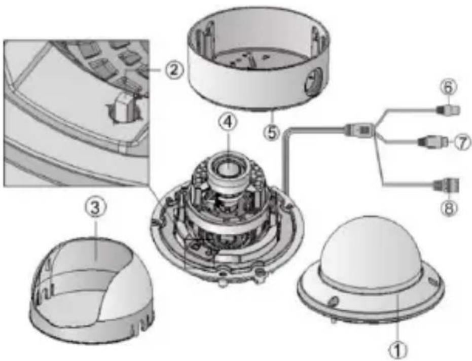
Table 1-1 Description
| No. | Description |
| 1 | Bubble |
| 2 | Menu Button (Joystick)Press this button to call out the on-screen menu. |
| 3 | Black Liner |
| 4 | Lens |
| 5 | Back Box |
| 6 | Power Cable ( 12 V DC or 24 V AC ) |
| 7 | Video Cable |
| 8 | Switch ButtonPress and hold this button for 5 seconds to switch the output from one mode to another among CVI (default mode) / TVI / AHD /CVBS. |
2 Installation
Before You Start
- Please make sure that the camera is in good condition and all of the assembly parts are included.
- Make sure that all related equipment is powered-off during the installation.
- Check that the camera specification agrees with the installation environment.
- To avoid damage, ensure the power supply voltage matches your camera requirements.
- Please make sure the installation surface is strong enough to withstand three times the weight of the camera and the mounting.
- If the installation surface is concrete, you need to insert expansion screws before you install the camera. If the installation surface is wood, you can use self-tapping screws to secure the camera.
- If the product does not function properly, please contact your dealer or the nearest service center. Do not disassemble the camera for repair or maintenance by yourself.
Note
For the camera that supports IR, you are required to pay attention to the following precautions to prevent IR reflection:
- Dust or grease on the dome cover will cause IR reflection. Please do not remove the dome cover film until the
Installation
installation is finished. If there is dust or grease on the dome cover, clean the dome cover with clean soft cloth and isopropyl alcohol.
- Make sure that there is no reflective surface too close to the camera lens. The IR light from the camera may reflect back into the lens and obscure the image.
- The foam ring around the lens must be seated flush against the inner surface of the bubble to isolate the lens from the IR LEDs. Fasten the dome cover to the camera body so that the foam ring and the dome cover are seamlessly connected.
Surface Mounting the Camera on a
Ceiling/Wall
Steps
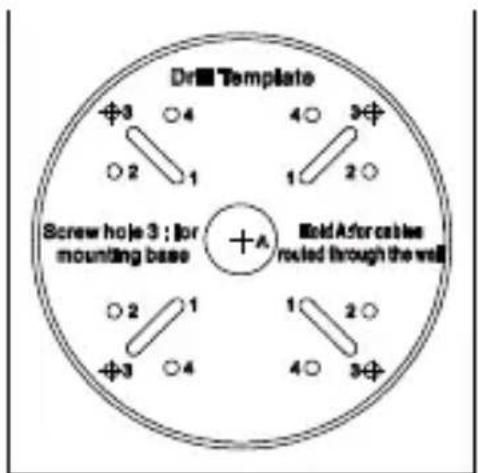
- Attach the mounting template (supplied) to the place where you want to install the camera, and then drill the screw holes and cable hole (if needed) in the ceiling/wall according to the mounting template.
Figure 2-1 HD273XD2 Mounting Template
1080P HQA Rugged Dome Camera User Guide
-
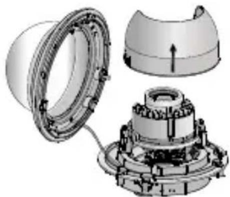
Loosen the three screws on the edge of the bubble with the supplied screwdriver to remove the bubble and the black liner.
-
Remove the camera from the back box.
Figure 2-2 Removing the Camera from the Back Box
natural_image
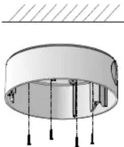
Exploded view diagram of a mechanical assembly showing internal components and housing (no text or labels)- Attach the back box to the ceiling/wall by aligning the holes of the back box with the holes drilled in step 1 and secure it to the ceiling/wall with the supplied screws.
Figure 2-3 Securing the Back Box
natural_image
Technical diagram of a cylindrical mechanical component with mounting holes and internal structure (no text or symbols)-
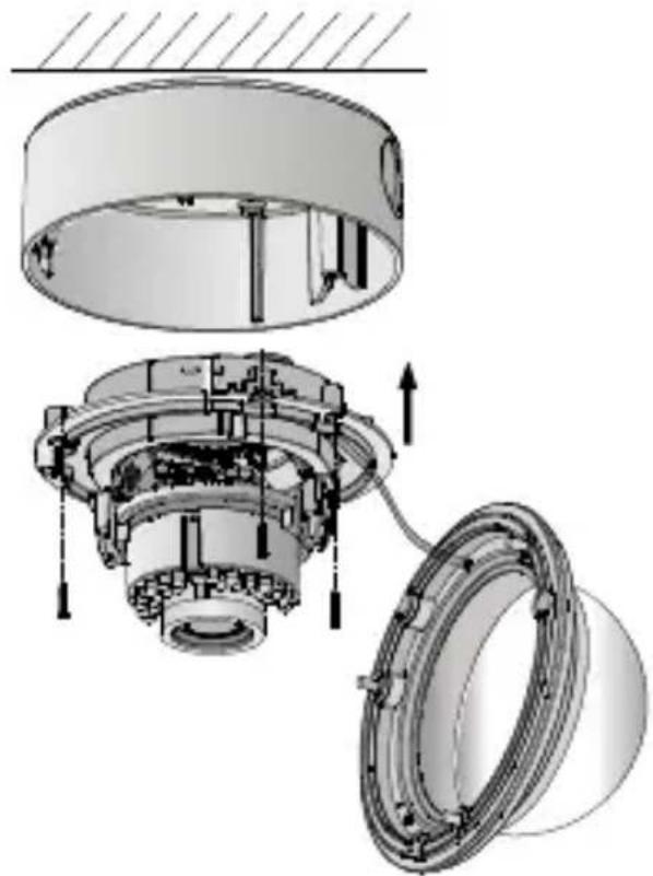
Route the cables through the cable hole.
-
Align the camera with the back box, and tighten the set screws to secure the camera with the back box.
Figure 2-4 Aligning the Camera
natural_image
Exploded view diagram of a mechanical assembly showing internal components and assembly (no text or labels)-
Connect the video output (BNC) connector to the monitor. Connect the power connector to the power supply.
-
Adjust the image and focus. See Adjusting the Image and Focus for details.
-
Fit the black liner back onto the camera
1080P HQA Rugged Dome Camera User Guide
Figure 2-5 Fitting the Black Liner
natural_image
Exploded view diagram of a mechanical assembly showing internal components and housing (no text or labels)- Tighten the screws to secure the bubble with the back box.
Figure 2-6 Securing the Bubble
natural_image
Technical diagram of a mechanical assembly with two views of a cylindrical component (no text or symbols)| Note | Remove the protection film softly after the installation is complete. Leaving the film on the bubble during installation will protect it from scratches during the installation process. |
In-ceiling Mounting the Camera
| Note | You need to purchase an in-ceiling mount separately if your installation requires an in-ceiling mounting. |
Steps
- Attach the mounting template (supplied) to the place where you want to install the camera, and then drill the screw holes and cable hole in the ceiling according to the mounting template.
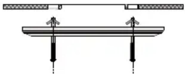
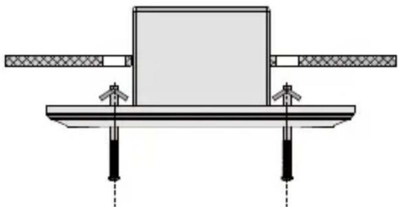
- Secure the in-ceiling mount with two mounting screws as shown in figure below:
Figure 2-7 Securing the In-ceiling Mount
natural_image
Pure mechanical assembly diagram showing two vertical supports and a horizontal beam with arrows indicating force or motion (no text or symbols)- Route the cables through the hole in the center of the in-ceiling mount.
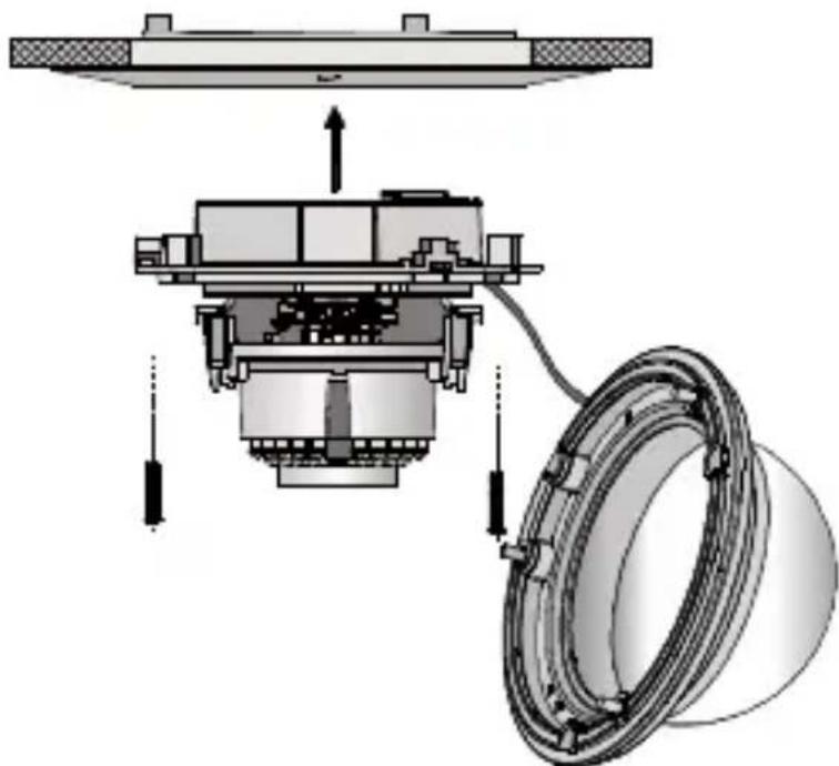
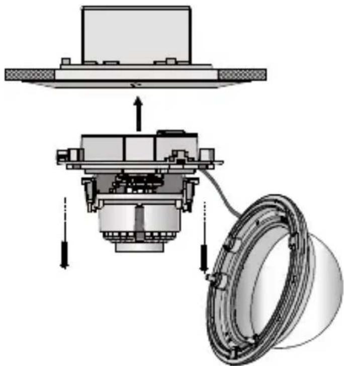
- Align the camera with the in-ceiling mount, and tighten the set screws to secure the camera with the in-ceiling mount.
1080P HQA Rugged Dome Camera User Guide
Figure 2-8 Securing the Camera
natural_image
Mechanical assembly diagram showing a bearing housing and mechanical components (no text or labels)- Connect the video output (BNC) connector to the monitor. Connect the power connector to the power supply.
- Adjust the image and focus. See Adjusting the Image and Focus for details.
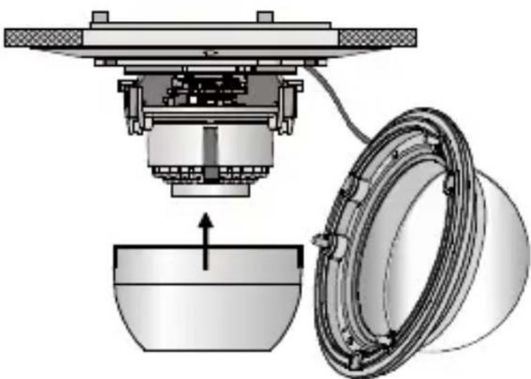
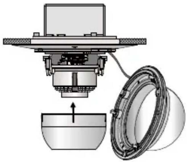
- Fit the black liner back onto the camera.
Figure 2-9 Fitting the Black Liner
natural_image
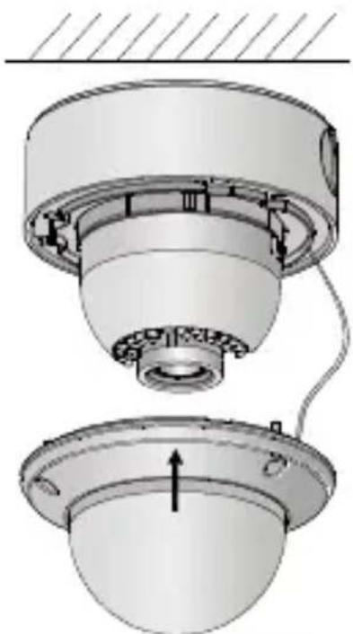
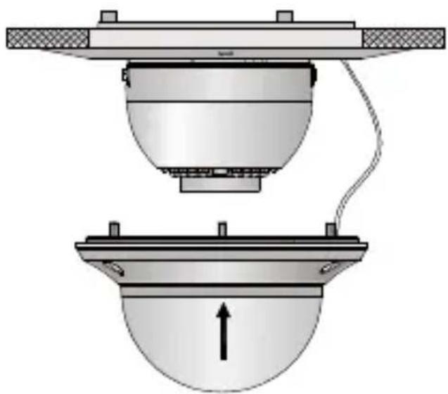
Mechanical assembly diagram showing a presser lifting a bowl, with a circular component partially visible (no text or symbols)Installation
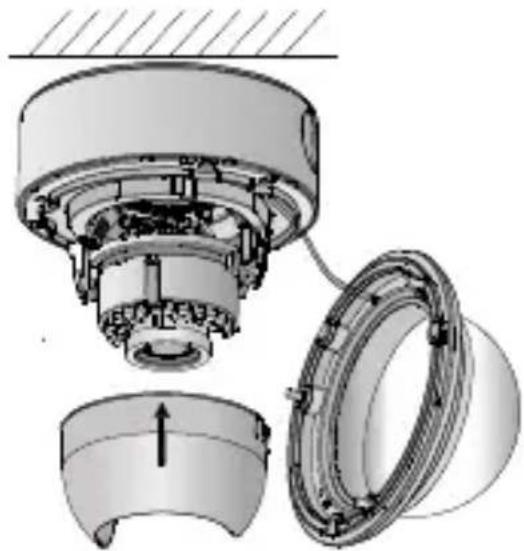
- Align the bubble with the in-ceiling mount, and then tighten the screws to secure the bubble to the in-ceiling mount.
Figure 2-10 Aligning the Bubble
natural_image
Diagram of a mechanical or electrical component with two views: top shows a dome-like structure, bottom shows a dome-shaped component with an upward arrow (no text or symbols)| Note | Remove the protection film softly after the installation is complete. Leaving the film on the bubble during installation will protect it from scratches during the installation process. |
In-ceiling Mounting the Camera with a Gang Box
Steps
- Secure the in-ceiling mount (supplied) to the gang box with two screws.
Figure 2-11 Securing the In-ceiling Mount to the Gang Box
natural_image
Technical diagram of a mechanical assembly with two vertical supports and a central block (no text or symbols)- Route the cables through the hole in the center of the in-ceiling mount.
- Align the camera with the gang box, and tighten the screws to secure the camera with the gang box.
Figure 2-12 Securing the Camera
natural_image
Mechanical assembly diagram showing a housing, gear mechanism, and bearing assembly (no text or labels)- Connect the video output (BNC) connector to the monitor. Connect the power connector to the power supply.
Installation
- Adjust the image and focus. See Adjusting the Image and Focus for details.
- Fit the black liner back onto the camera.
Figure 2-13 Fitting the Black Liner
natural_image
Technical diagram of a mechanical assembly with a component inserted into a bowl and a ring-like housing (no text or symbols)- Align the bubble with the in-ceiling mount, and tighten the screws to secure the bubble to the in-ceiling mount.
Figure 2-14 Securing the Bubble
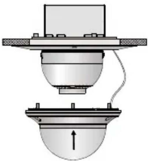
natural_image
Technical diagram of a mechanical assembly with a component and base, showing no text or symbols.| Note | Remove the protection film softly after the installation is complete. Leaving the film on the bubble during installation will protect it from scratches during the installation process. |
Adjusting the Image and Focus
Steps
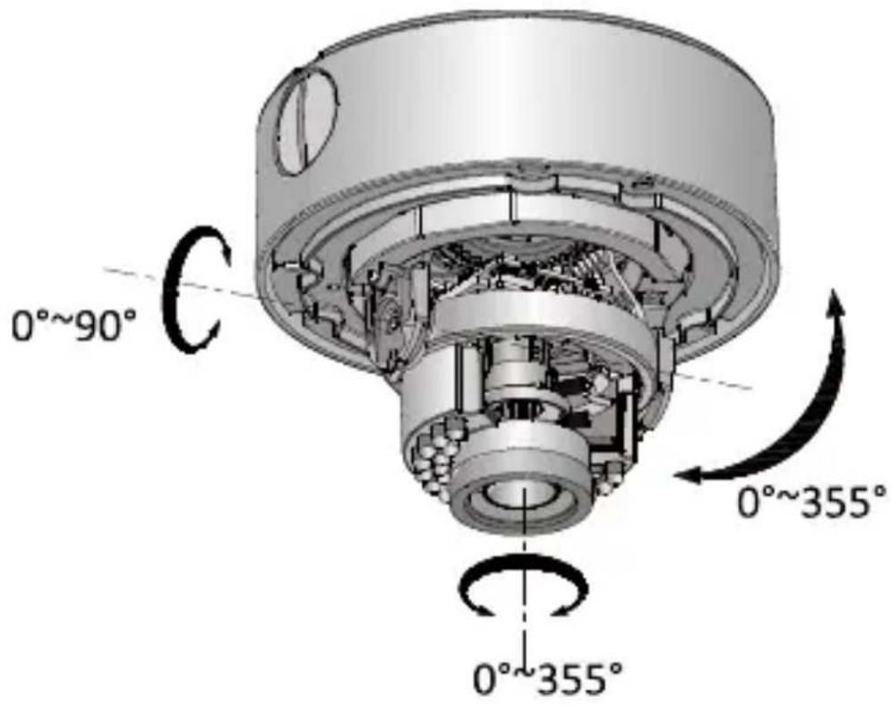
3-axis surveillance angle adjustment (see Figure 2-15 while adjusting the angle):
• View the camera image with the connected monitor.
- Rotate the panning table to adjust the pan direction [0°\~355°].
- Loosen the tilting lock screw.
- Rotate the tilting table to adjust the tilt direction [0°\~90°].
- Tighten the tilting lock screw.
- Rotate the camera [0°\~355°] to adjust the lens to the optimum surveillance angle.
Figure 2-15 3-axis Angle Adjustment
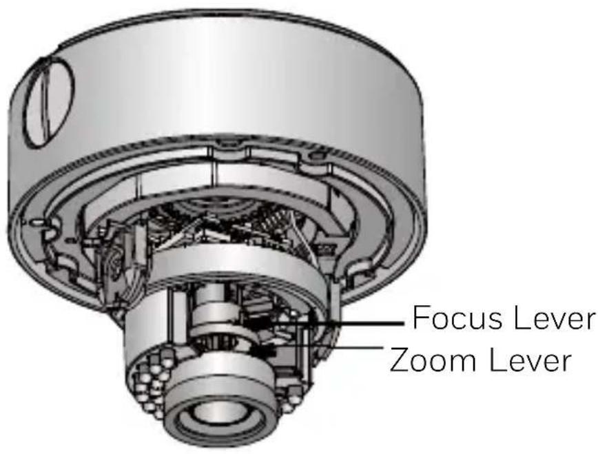
Zoom and focus adjustment:
• View the camera image with the connected monitor.
- Loosen the zoom lever and move the screw between T (Tele) and W (Wide) to obtain the optimum zoom setting.
• Tighten the zoom lever.
- Loosen the focus lever and move the screw between F (Far) and N (Near) to obtain the optimum focus setting.
• Tighten the focus lever.
1080P HQA Rugged Dome Camera User Guide
Figure 2-16 Zoom and Focus Adjustment
3 Menu Description
Figure 3-1 Main Menu Overview
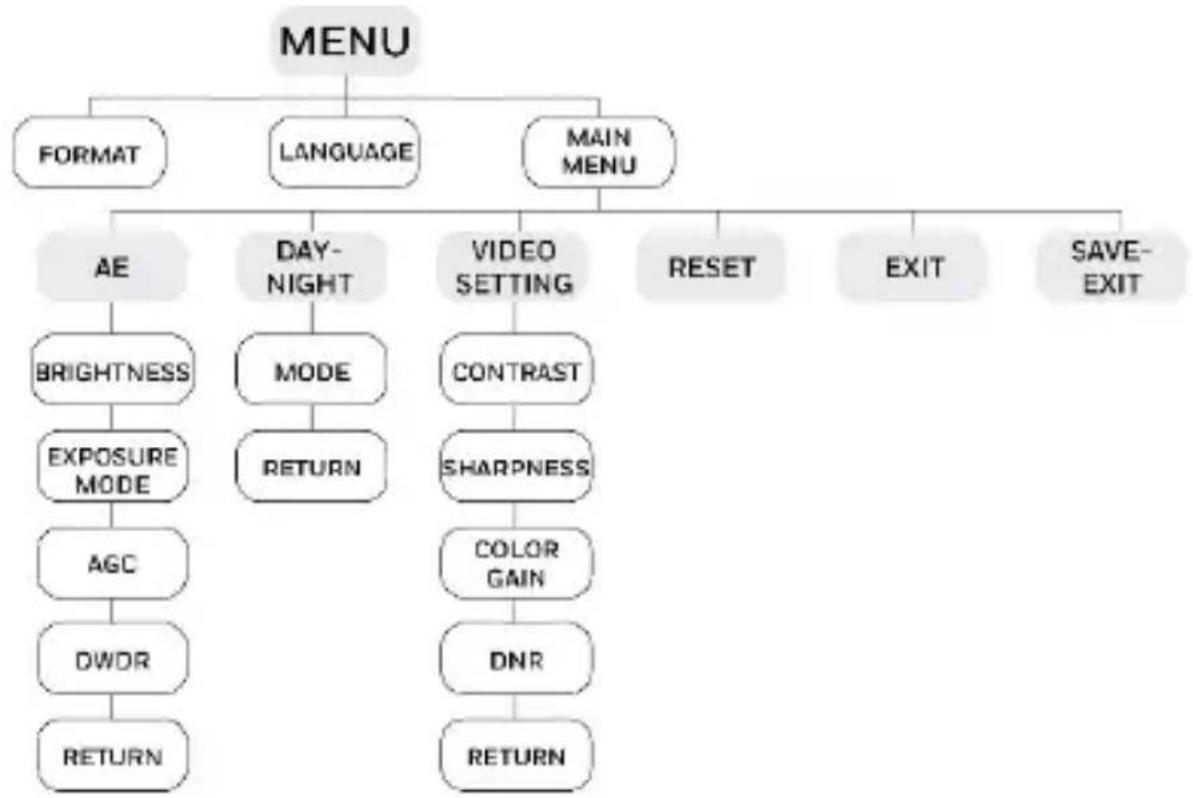
flowchart
graph TD
    A["MENU"] --> B["FORMAT"]
    A --> C["LANGUAGE"]
    A --> D["MAIN MENU"]
    D --> E["AE"]
    E --> F["BRIGHTNESS"]
    F --> G["EXPOSURE MODE"]
    G --> H["AGC"]
    H --> I["DWOR"]
    I --> J["RETURN"]
    E --> K["DAY-NIGHT"]
    K --> L["MODE"]
    L --> M["RETURN"]
    K --> N["VIDEO SETTING"]
    N --> O["CONTRAST"]
    O --> P["SHARPNESS"]
    P --> Q["COLOR GAIN"]
    Q --> R["DNR"]
    R --> S["RETURN"]
    N --> T["RESET"]
    T --> U["EXIT"]
    U --> V["SAVE-EXIT"]
Note
- This camera uses a joystick to select the menu and confirm a selection (see Figure 1-1 for the joystick location).
- Move the joystick up/down to select a menu item.
- Move the joystick left/right to adjust the value of the selected item.
- Press down on the joystick to confirm a selection. The menu button mentioned in the chapter below refers to the joystick.
FORMAT
You can set the video format as 1080P25 (PAL) or 1080P30 (NTSC).
LANGUAGE
You can set the language as Chinese or English.
AE (Auto Exposure)
AE describes the brightness-related camera parameters. You can adjust the image brightness by changing the BRIGHTNESS, EXPOSURE MODE, AGC, and DWDR values in different light conditions.
Figure 3-2 AE Menu
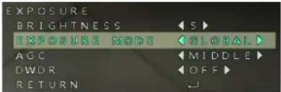
BRIGHTNESS
Brightness refers to the brightness of the image. The value ranges from 1 to 10. The higher the value is, the brighter the image will be.
EXPOSURE MODE
- GLOBAL
GLOBAL refers to the normal exposure mode for situations such as unusual lighting distribution, variations, non-standard processing, or other conditions.
- BLC
BLC refers to the back-light compensation. This technology is designed to optimize the brightness of images through using digital signal processing. The value ranges from 0 to 8.
AGC
AGC optimizes the clarity of an image in a poorly light scene. The AGC level can be set as HIGH, MIDDLE, or LOW. Select OFF to disable AGC.
Note
The noise will be amplified if the AGC is on.
DWDR
The digital wide dynamic range (DWDR) function helps the camera provide clear images even under back light circumstances. When there are both very bright and very dark areas simultaneously in the field of view, DWDR balances the brightness level of the whole image and provides clear images with visible details
DAY & NIGHT
Figure 3-3 Day-Night Menu
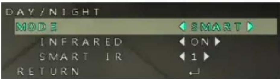
INFRARED
You can select to turn the infrared lamp ON/OFF to respond to the requirements of different circumstances.
SMART IR
The SMART IR function is used to adjust the light to its most suitable intensity and to prevent the image from over exposure. The value ranges from 0 to 5. The higher the value is, the more obvious the SMART IR effect will be. SMART IR is disabled when the value is 0.
VIDEO SETTING
Figure 3-4 Video Setting Menu
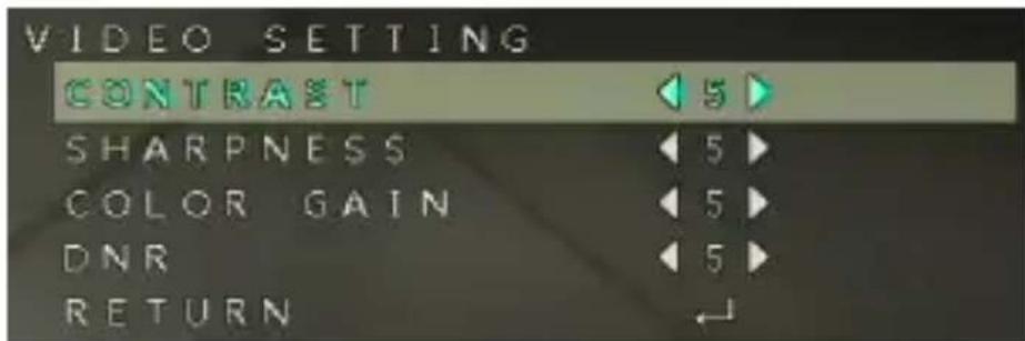
CONTRAST
Contrast enhances the difference in color and light between parts of an image. The value ranges from 1 to 10.
SHARPNESS
Sharpness determines the amount of detail an imaging system can reproduce. And you can adjust the EDGE/DETAIL sharpness value by entering the SHARPNESS submenu. The value ranges from 1 to 10. A higher sharpness value results in a clearer and sharper image.
COLOR GAIN
Adjust this feature to change the saturation of the color. The value ranges from 1 to 10.
DNR
DNR decreases the noise effect, especially when capturing moving images in low-light conditions and delivering more
1080P HQA Rugged Dome Camera User Guide
accurate and sharp image quality. The value ranges from 1 to 10.
RETURN
Return to the previous menu.
RESET
Reset all the settings to their default settings.
EXIT
Exit the menu without saving the settings.
SAVE-EXIT
Save the settings and exit the menu.
Honeywell Security Products Americas (Head Office)
2700 Blankenbaker Pkwy, Suite 150
Louisville, KY 40299, USA
www.honeywell.com/security
+1 800 323 4576
Honeywell Security Europe/South Africa
Aston Fields Road, Whitehouse Industrial Estate
Runcorn, WA7 3DL, United Kingdom
www.honeywell.com/security/uk
+44 (0) 1928 754 028
Honeywell Security Products Americas Caribbean/Latin America
9315 NW 112th Ave. Miami, FL 33178, USA
www.honeywell.com/security/clar
+1 305 805 8188
Honeywell Security Asia Pacific
Building #1, 555 Huanke Road, Zhang Jiang Hi-Tech Park,
Pudong New Area, Shanghai, 201203, China
www.asia.security.honeywell.com
+86 400 840 2233
Honeywell Security Middle East/N. Africa
Emaar Business Park, Sheikh Zayed Road Building No. 2, Office No. 301
Post Office Box 232362
Dubai, United Arab Emirates
www.honeywell.com/security/me
+971 (0) 4 450 5800
Honeywell Security Northern Europe
Ampèrestraat 41
1446 TR Purmerend, The Netherlands
www.honeywell.com/security/nl
+31 (0) 299 410 200
72458 Albstadt, Germany
www.honeywell.com/security/de
+49 (0) 7431 801-0
Honeywell Security France
Immeuble Lavoisier
92160 Antony, France
www.honeywell.com/security/fr
+33 (0) 1 40 96 20 50
Honeywell Security Italia SpA
Via Achille Grandi 22, 20097 San Donato
Milanese (MI), Italy
www.security.honeywell.com/it
Honeywell Security España
Avenida de Italia, n° 7, 2 ^a planta C.T.
Coslada
28821 Coslada, Madrid, Spain
www.honeywell.com/security/es
+34 902 667 800
www.honeywell.com/security/ru
+7 (495) 797-93-71
Honeywell
www.honeywellvideo.com
+1.800.323.4576 (North America only)
https://www.honeywellsystems.com/ss/techsupp/index.html
Document 800-24685 - Rev A - 11/2018
© 2018 Honeywell International Inc. All rights reserved. No part of this publication may be reproduced by any means without written permission from Honeywell. The information in this publication is believed to be accurate in all respects. However, Honeywell cannot assume responsibility for any consequences resulting from the use thereof. The information contained herein is subject to change without notice. Revisions or new editions to this publication may be issued to incorporate such changes.