HN30080216 - Security Camera HONEYWELL - Free user manual and instructions
Find the device manual for free HN30080216 HONEYWELL in PDF.

| Product Type | Security Camera |
| Model | HN30080216 |
| Brand | Honeywell |
| Dimensions | 6.5 x 6.5 x 9.5 cm |
| Weight | 0.5 kg |
| Power Supply | DC 12V, 1A adapter included |
| Resolution | 1080p (1920 x 1080) Full HD |
| Night Vision | Yes, IR LEDs up to 10 meters |
| Field of View | 130° diagonal |
| Connectivity | Wi-Fi 802.11 b/g/n (2.4 GHz), Ethernet port |
| Storage | microSD card up to 128 GB (not included) |
| Weatherproof Rating | IP65 (outdoor use) |
| Motion Detection | Yes, adjustable sensitivity and zones |
| Two-Way Audio | Built-in microphone and speaker |
| Mobile App | Honeywell Home app (iOS & Android) |
| Audio Alert | Siren (85 dB) |
| Mounting | Wall or ceiling mount (hardware included) |
| Operating Temperature | -20°C to 50°C (-4°F to 122°F) |
| Security Features | Encrypted video, password protection, two-factor authentication |
| Cleaning | Wipe with dry, soft cloth; do not use harsh chemicals |
| Maintenance | Check connections and update firmware regularly |
| Spare Parts | Power adapter, mounting bracket, screws available from Honeywell support |
| Repairability | User-replaceable microSD and power adapter; professional repair for other issues |
Frequently Asked Questions - HN30080216 HONEYWELL
User questions about HN30080216 HONEYWELL
0 question about this device. Answer the ones you know or ask your own.
Ask a new question about this device
Download the instructions for your Security Camera in PDF format for free! Find your manual HN30080216 - HONEYWELL and take your electronic device back in hand. On this page are published all the documents necessary for the use of your device. HN30080216 by HONEYWELL.
USER MANUAL HN30080216 HONEYWELL
Honeywell 30 Series Network Video Recorder
HN300802xxx
HN301602xxx
(X: may be any alphanumeric character for HDD information)
User Guide
Cautions and Warnings


CAUTION: TO REDUCE THE RISK OF ELECTRIC SHOCK, DO NOT REMOVE THE COVER. NO USER-SERVICEABLE PARTS INSIDE. REFER SERVICING TO QUALIFIED SERVICE PERSONNEL.
THIS SYMBOL INDICATES THAT DANGEROUS VOLTAGE CONSTITUTING A RISK OF ELECTRIC SHOCK IS PRESENT WITHIN THE UNIT.

THIS SYMBOL INDICATES THAT IMPORTANT OPERATING AND MAINTENANCE INSTRUCTIONS ACCOMPANY THIS UNIT.

WARNING Installation and servicing should be performed only by qualified and experienced technicians to conform to all local codes and to maintain your warranty.
WARNING Use only with the supplied power cable. Power output: 120W for 8 channels / 200W for 16 channels (1-8 channels cannot be exceeded 100W and 9-16 channels cannot be exceeded 100W) PoE 802.3at in total.
CAUTION The Honeywell product uses a 3.0V CR1220 lithium battery as the power supply for its internal real-time clock (RTC). Low battery power affects the operation of the RTC, causing it to reset at every power-up.
Risk of explosion if the battery is incorrectly replaced.
Dispose of used batteries according to local regulations or the battery manufacturer's instructions.
Replace only with an identical battery or a battery which is recommended by Honeywell.
Regulatory Statements
FCC Compliance Statement
Information to the User: This equipment has been tested and found to comply with the limits for a Class A digital device, pursuant to part 15 of the FCC Rules. These limits are designed to provide reasonable protection against harmful interference when the equipment is operated in a commercial environment. This equipment generates, uses, and can radiate radio frequency energy and, if not installed and used in accordance with the instruction manual, may cause harmful interference to radio communications. Operation of this equipment in a residential area is likely to cause harmful interference in which case the user will be required to correct the interference at his own expense. Changes or modifications not expressly approved by the party responsible for compliance could void the user's authority to operate the equipment.
CAUTION: This is a Class A product. In a domestic environment, this product may cause radio interference in which case the user may be required to take adequate measures.
This Class A digital apparatus complies with Canadian ICES-003.
Please visit https://mywebtech.honeywell.com/Home to check the complete FCC documents.
Manufacturer's Declaration of Conformance
North America
The equipment supplied with this guide conforms to UL 62368-1 and CSA C22.2 No. 62368-1.
Europe
The manufacturer declares that the equipment supplied is compliant with the European Parliament and Council Directive on the restriction of the use of certain hazardous substances in electrical and electronic equipment (2015/863/EU), the Low Voltage Directive (2014/35/EU) and the essential requirements of the EMC directive (2014/30/EU), conforming to the requirements of standards EN 55032 for emissions, EN 50130-4 for immunity, and EN 62368-1 for electrical equipment safety.
Waste Electrical and Electronic Equipment (WEEE)

Correct Disposal of this Product (applicable in the European Union and other European countries with separate collection systems).
This product should be disposed of, at the end of its useful life, as per applicable local laws, regulations, and procedures.
Eurasian Conformity (EAC) RoHS
EAC
General Data Protection Regulation
Please be aware that this product can store personal data.
Personal data is protected by the General Data Protection Regulation (2016/679) in Europe and therefore the owners of personal data have obtained certain rights thanks to this regulation.
We strongly advise you to be fully aware of these owner (“data subjects”) rights as well as which limitations you have to obey regarding the use and distribution of this data.
Further details can be found on the GDPR website of the EU: https://ec.europa.eu/commission/priorities/justice-and-fundamental-rights/data-protection/2018-reform-eu-data-protection-rules_en
Important Safeguards
Read and keep these instructions.
- Please ensure that your installation area can safely support the weight of the unit.
- Do not drop the unit or subject it to physical shock.
- Avoid operating or storing the unit in extremely humid, dusty, hot/cold environments, where the operating temperature is outside the recommended range of 14°F to 131°F (-10°C to 55°C). HN300802xxE/HN301602xxE: 14°F to 113°F (-10°C to 45°C).
- Avoid operating the unit close to sources of powerful electromagnetic radiation, such as radio or TV transmitters.
- Ensure to connect the power cord to a socket-outlet with earthing connection, or equivalent.
• The product is only to be connected to PoE network without routing to outside plant.
Safety Instructions
Before installing or operating the unit, read and follow all instructions. After installation, retain the safety and operating instructions for future reference.
- HEED WARNINGS - Adhere to all warnings on the unit and in the operating instructions.
- INSTALLATION
• Install in accordance with the manufacturer's instructions.
- Installation and servicing should be performed only by qualified and experienced technicians to conform to all local codes and to maintain your warranty.
- Any wall or ceiling mounting of the product should follow the manufacturer's instructions and use a mounting kit approved or recommended by the manufacturer.
- POWER SOURCES - This product should be operated only from the type of power source indicated on the marking label. If you are not sure of the type of power supplied to your facility, consult your product dealer or local power company.
- MOUNTING SYSTEM - Use only with a mounting system recommended by the manufacturer or sold with the product.
- ATTACHMENTS/ACCESSORIES - Do not use attachments/accessories not recommended by the product manufacturer as they may result in the risk of fire, electric shock, or injury to persons.
- CLEANING - Do not use liquid cleaners or aerosol cleaners. Use a damp cloth for cleaning.
- SERVICING - Do not attempt to service this unit yourself. Refer all servicing to qualified service personnel.
- REPLACEMENT PARTS - When replacement parts are required, be sure the service technician has used replacement parts specified by the manufacturer or have the same characteristics as the original part. Unauthorized substitutions may result in fire, electric shock or other hazards. Using replacement parts or accessories other than the original manufacturers may invalidate the warranty.
Warranty and Service
Subject to the terms and conditions listed on the product warranty, during the warranty period Honeywell will repair or replace, at its sole option, free of charge, any defective products returned prepaid.
In the event you have a problem with any Honeywell product, please call Customer Service for assistance or to request a Return Merchandise Authorization (RMA) number.
Be sure to have the model number, serial number, and the nature of the problem available for the technical service representative.
Prior authorization must be obtained for all returns, exchanges, or credits. Items shipped to Honeywell without a clearly identified Return Merchandise Authorization (RMA) number may be refused.
List of Symbols
The following is a list of symbols that might appear on the NVR.
Symbol Explanation
 | The WEEE symbol.This symbol indicates that when the end-user wishes to discard this product, it must be sent to separate collection facilities for recovery and recycling. By separating this product from other household-type waste, the volume of waste sent to incinerators or landfills will be reduced, and thus natural resources will be conserved. |
 | The UL compliance logo.This logo indicates that the product has been tested and is listed by the Underwriters Laboratories. |
 | The FCC compliance logo.This logo indicates that the product conforms to Federal Communication's Commission compliance standards. |
 | The direct current symbol.This symbol indicates that the power input/output for the product is direct current. |
 | The alternating current symbol.This symbol indicates that the power input/output for the product is alternating current. |
 | The LDPE symbol.This symbol indicates that this product is made of Low-Density Polyethylene (LDPE). |
 | The Direct Current symbol.This symbol indicates that the product operates from a 12 V direct current. |


The Lead-free symbol. This symbol indicates that the product does not contain lead (Pb).
The CCC compliance logo. This logo indicates that the product conforms with the China Compulsory Certification guidelines.
The Environment Friendly Use-period symbol. This symbol indicates the length of time that this electronic product can used without harming the environment.
The RCM Compliance symbol. This symbol indicates that the product conforms with the Australian RCM guidelines.
The TVU Lab symbol. This symbol indicates that the product has been safety tested by the TUV Lab.
The Direct Current symbol. This Direct Current symbol indicates that the product operates direct current.
This symbol indicates that the product is to be used indoors.
The CE Compliance logo. This logo indicates that the product conforms to the relevant guidelines/standards for the European Union harmonization legislation.
The Protective Earth symbol. This symbol indicates that the marked terminal is intended for connection to the protective earth/grounding conductor.
This symbol is used to direct attention to important information.
This symbol warns that the corresponding action could result in an electric shock.
This symbol indicates On/Standby functionality of the corresponding control/button/switch.
Eurasian Conformity (EAC) RoHS
Regulatory Information
The regulatory information herein might vary according to the model you purchased. Some information is only applicable for the country or region where the product is sold.
FCC Information

CAUTION
Changes or modifications not expressly approved by the party responsible for compliance could void the user's authority to operate the equipment.
FCC conditions
This device complies with part 15 of the FCC Rules. Operation is subject to the following two conditions:
• This device may not cause harmful interference.
- This device must accept any interference received, including interference that may cause undesired operation.
FCC compliance
This equipment has been tested and found to comply with the limits for a digital device, pursuant to part 15 of the FCC Rules. This equipment generates, uses, and can radiate radio frequency energy and, if not installed and used in accordance with the instructions, may cause harmful interference to radio communication.
- For class A device, these limits are designed to provide reasonable protection against harmful interference in a commercial environment. Operation of this equipment in a residential area is likely to cause harmful interference in which case the user will be required to correct the interference at his own expense.
- For class B device, these limits are designed to provide reasonable protection against harmful interference in a residential installation. However, there is no guarantee that interference will not occur in a particular installation. If this equipment does cause harmful interference to radio or television reception, which can be determined by turning the equipment off and on, the user is encouraged to try to correct the interference by one or more of the following measures:
• Reorient or relocate the receiving antenna.
- Increase the separation between the equipment and receiver.
- Connect the equipment into an outlet on a circuit different from that to which the receiver is connected.
- Consult the dealer or an experienced radio / TV technician for help.
Privacy Protection Notice
As the device user or the data controller, you might collect personal data or others such as face, fingerprints, car plate number, Email address, phone number and GPS and so on. You need to be in compliance with the local privacy protection laws and regulations to protect the legitimate right and interest of other people by implementing measures include but not limited to: providing clear and visible identification to inform data subject the existence of surveillance area and providing related contact.
Table of Contents
About This Document ....x
Overview of Contents ....x
Special Fonts and Symbols....x
How to Use This Document ....x
1 Introduction....1
Overview of the Network Video Recorder....1
Features of the Network Video Recorder....1
Network Video Recorder Components 2
Using the On-screen Keyboard....4
2 Getting Started....5
Connecting External Devices 5
Devices Connection 6
Starting and Shutting Down the NVR 6
Starting the NVR 6
Shutting Down/Reboot the NVR....6
Device Initialization....7
3 Viewing Live Video 12
About Live View 12
Live View Window....13
Toolbars....13
Shortcut Menu 15
Working with the PTZ Control Panel (If applicable) 16
Configuring PTZ Settings....17
4 Recording Video....18
Manual Recording....18
Scheduled Recording....18
5 Playing Back and Search Videos....20
Playing Recording Clips....20
Searching Videos 21
Timeline Bar....23
Backing Up Video....24
To Back Up Using the Playback Timeline Bar 24
To Back Up Using the Main Tool Bar 25
6 Settings....27
Setting-Camera-Management 27
Change Password 27
Adding a Camera 29
Removing a Camera....29
Network 30
Camera Position....31
Setting-Camera-Media 32
Stream Management....32
Video 34
Audio 35
Setting-Camera-Schedule 35
Recording Options 35
Schedule 36
Setting-Camera-Image 38
Display 38
Image Adjustment....38
Setting-Camera-Motion Detection 39
Setting-Camera-PTZ settings....40
Setting-Event-Event....41
Creating an Event....41
Removing an Event....46
Setting-Event-Email 46
Creating a Volume....54
Verify 57
Settings-Network-IP 57
Settings-Network-Service....58
Settings-Network-P2P 59
7 Management over a Web Console....60
Before Getting Started....60
Login 61
Live View Screen....62
Camera List 63
Layout....64
Layout Contents 64
Time & Log out....65
Live View Window 65
PTZ Panel....66
Event Panel....67
Search Recording Clips Screen 68
Camera List....69
Layout 70
Playback Panel 70
Event Panel....71
Settings Screen 72
About This Document
This document introduces the Honeywell 30 Series Network Video Recorder. It explains how to operate the Network Video Recorder.
This document is intended for installers and users.
Overview of Contents
This document contains the following chapters:
• Chapter 1, Introduction, describes the features, front and rear panel layout of the NVR.
- Chapter 2, Getting Started, describes how to connect the NVR and log on to its user interface.
- Chapter 3, Viewing Live Video, describes the NVR's real-time monitoring mode and associated NVR operations, including controlling a PTZ camera (if connected).
- Chapter 4, Recording Video, describes how to manually record a video clip and how to set up automatic recording.
- Chapter 5, Playing Back and Search Videos, describes how to search for and play back recorded video, and how to save recorded files to an external storage device.
• Chapter 6, Settings, describes how to configure NVR settings.
- Chapter 7, Management over a Web Console, describes how to operate the NVR's through web client.
Special Fonts and Symbols
| Italic | Indicates referenced chapter, figure number, page number, etc. In the electronic version, click on italicized text to switch to the corresponding page. |
| Bold | Indicates a button, or menu item. |
| Note | Alerts the user to the presence of important operating and maintenance (servicing) instructions in the literature accompanying the product. |
How to Use This Document
• Pictures in this manual are for reference only, please see the actual items for details.
• This product is subject to updates or changes without prior notice.
- Please familiarize yourself with this manual before operation and ensure its accessibility for future use.
- The manual has been reviewed and its accuracy is guaranteed. If there is any uncertainty or controversy, please refer to the final explanation of Honeywell. Honeywell does not take any responsibility for any consequences caused by the misunderstanding of the manual or incorrect operations by the user.
1 Introduction
This chapter contains the following sections:
• Overview of the Network Video Recorder on page 1.
• Features of the Network Video Recorder on page 1.
• Network Video Recorder Components on page 2.
Overview of the Network Video Recorder
The 30 Series Network Video Recorder is a high-performance network video recorder. It supports:
- Local Live View
• Multiple-window display - Local recorded file storage
- Mouse shortcut menu operation
The 30 Series Network Video Recorder also features multiple storage options:
- USB storage
- Front-end storage: The NVR's HDD storage
Because of the flexibility of its design, the 30 Series Network Video Recorder can be used in a variety of applications, such as public security, water conservancy, transportation, and education.
Features of the Network Video Recorder
User Management
• Different user rights for each group; each user belongs to a specific group.
• User rights cannot exceed Group rights.
Storage
- Supports central server backup that follows your configuration and setup in Alarm or Schedule settings.
• Supports recording through the Internet. The recorded files are stored on the client's PC.
Alarm
- Responds to external alarms almost instantly, based on your pre-defined relay setup. You can also configure a buzzer prompt upon alarm detection.
Network Monitor
- The NVR supports the transmission of audio/video data that is compressed by an IP camera, which is then decoded for display. The delay time is more than 500 ms (sufficient network bandwidth support is required).
- Compatible to broadcast audio/video with the following transmission protocols: HTTP, HTTPS, TCP, RTP/RTCP.
• Transmits some alarm data or alarm information through SMTP.
• Supports Internet access through the WAN.
Window Split
Video compression plus a digital process allows the NVR to split the monitor screen to show up to 8 video channels (HN300802xxx)/16 video channels(HN301602xxx) at the same time.
Recording
Supports a schedule for recording. The recorded files can be saved in the HDD. You can search and view the recorded video that is stored locally or through the Internet connection.
Backup
Supports backing up video to a USB device on local side or to PC client on web side.
Network Management
• Supports NVR configuration and management through the Internet.
• Supports device management through the Internet.
Auxiliary
• Supports viewing real-time system resources information and running statistics display.
- Supports log file.
- Supports local GUI output and shortcut menu operation with a computer mouse and keyboard.
• Supports setting up the configuration of a camera.
Network Video Recorder Components
Figure 1-1 NVR Front Panel
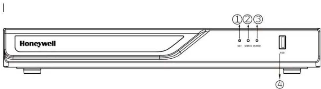
Table 1-1 NVR Front Panel Description
| Name | Behavior | Definitions |
| 1. Network uplink status/activity LED | Blinking Green | Data is being transmitted or received. |
| OFF The Ethernet uplink is disconnected. | ||
| 2. System status LED | Constant Green System ready. | |
| Blinking Green every 1 second | Updating firmware or device pack. | |
| Constant Red | 1. S.M.A.R.T.-related disk errors.2. A configured HDD is missing.3. HDD is full. Buzzer will also be sounded. When buzzer is turned off, LED will return normal. | |
| 3. Power status LED | Solid Green The NVR is powered on. | |
| OFF The NVR is powered off. | ||
| 4. USB port | ||
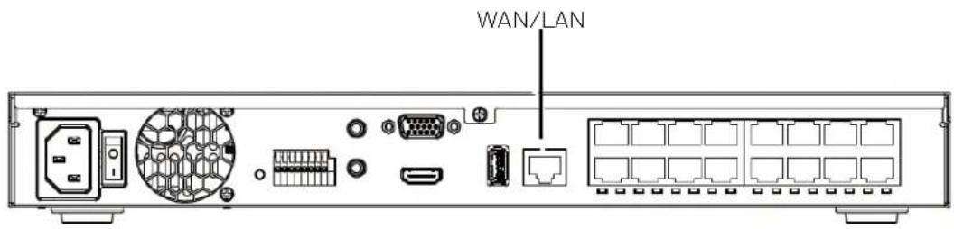
Figure 1-2 NVR Back Panel
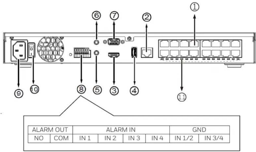
Table 1-2 NVR Back Panel Description
| 1 | HN300802xxx: PoE ports # 1 to #8 for connecting to cameras directly. | 7 VGA | |
| HN301602xxx: PoE ports # 1 to #16 for connecting to cameras directly. | |||
| 2 | RJ45 port - GbE uplink | 8 | Alarm In/Alarm Out terminal block |
| 3 | HDMI 9 Power socket (110/240V AC) | ||
| 4 | USB port 10 Power Switch | ||
| 5 | Audio IN (Reserved) 11 | Channel LED: 1 to 8 / 16 (from left to right) | |
| 6 | Audio OUT |
Using the On-screen Keyboard
- To display the on-screen keyboard, click 📋 on the main toolbar (see Figure 3-3 Main Toolbar) in live view screen to go to the settings screen.
- Click 📄 on the menu to expand the on-screen keyboard.
Figure 1-3 On-screen Keyboard
![1 2 3 4 5 6 7 8 9 0 q w e r t y u i o p [ ] \ a s d f g h j k l ; ' - Enter z x c v b n m @ . . / ↺ ↑](/content/2026/05/1059361/images/550cbb49ee755cd3ca8912ee1ed768df0efe30dafa87a6deefa604f10c60c7ea.jpg)
• To switch between lowercase and uppercase letters, click
• To delete the previous character, click
- To insert a space, click

- Click Enter or ✗ to close the on-screen keyboard.
2 Getting Started
This chapter contains the following sections:
• Connecting External Devices on page 5.
• Starting and Shutting Down the NVR on page 6.
• Device Initialization on page 7.
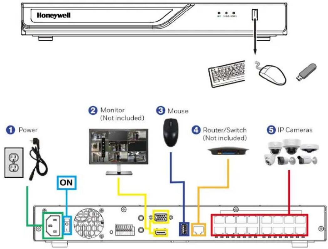
Connecting External Devices
- Connect the cameras
Connect the RJ45 network cables from the cameras to PoE ports.
- Connect the monitor
Connect a VGA cable (not supplied) to the VGA interface and/or an HDMI cable (not supplied) to the HDMI interface. Connect the other end to a monitor (do not use a TV). Simultaneous VGA and HDMI output is supported.
- Connect the mouse
Connect the supplied USB mouse to the USB port.
- Connect the Ethernet cable
Connect the supplied CAT5e Ethernet cable to the network port. Connect the other end to a router on your network.
- Connect audio devices (if applicable)
To record audio, connect the audio sources to the AUDIO IN connectors. To play audio, connect an audio output device (low-impedance headphones, speaker, or amplifier) to the AUDIO OUT connector (200 mV / 1 kilohm).
- Connect alarm devices (if applicable)
Connect alarm devices to the alarm in/out interface. If the alarm inputs use external power, the device must have the same ground as the NVR.
- Connect a PTZ camera (if applicable)
Your embedded NVR communicates with PTZ cameras through the Network. Ensure that your camera is correctly connected to the Network.
- Connect the power cable
Use only with the supplied power cable. Power output: 120W for 8 channels / 200W for 16 channels. PoE 802.3at in total. Use of an uninterruptible power supply (UPS) is strongly recommended.
Devices Connection
The following diagram shows a typical NVR connection:
Figure 2-1 Devices Connection
Starting and Shutting Down the NVR
Starting the NVR
- Verify that the NVR is connected to an appropriate power source.
- Turn on the power switch (See No. 11 in Figure 1-2) on the back panel to start the NVR.
Shutting Down/Reboot the NVR
To prevent damage to the hard drive, follow these steps to shut down the NVR:
- In live view screen, click (Main Menu) on the main toolbar (see Figure 3-3 Main Toolbar).
Figure 2-2 Main Menu
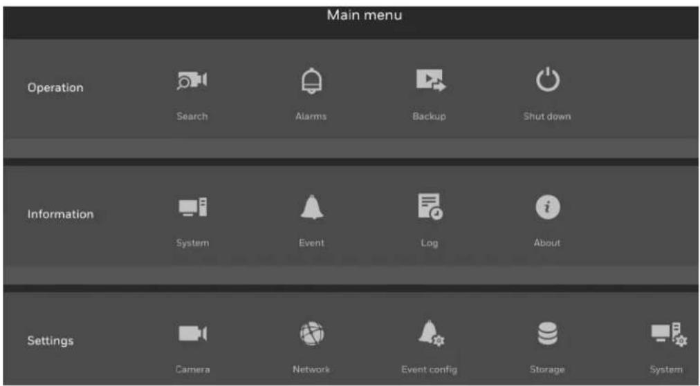
- In the Main Menu window, click 📄 Shut down.
Figure 2-3 Shutdown
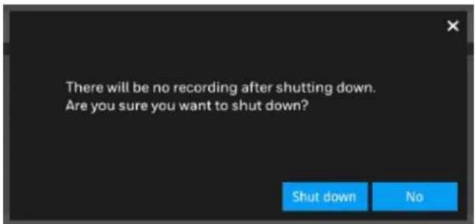
- Click Shut down button.
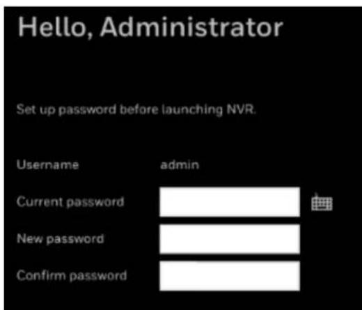
Device Initialization
When the NVR has booted up, set password before launching NVR.
Figure 2-4 Device Initialization –Password Setup
Password must:
Be following characters: A-Z, a-z, 0-9, and 1%-.@^\~
√ Be between 8-64 characters with no space
√ Be at least 1 numeric, 1 uppercase, 1 lowercase and 1 special character
√ Not begin with a special character
- Enter the current password "1234" and set the new password according to the password requirements. The default username is admin.
You can use the USB mouse to input the password. Click 📄 to expand the on-screen keyboard to switch the input mode between numbers and English letters; click ↑ to change between lowercase and uppercase.
- When the password setup is completed, click Apply and the following window is displayed:
Figure 2-5 Device Initialization-Language and Time Zone
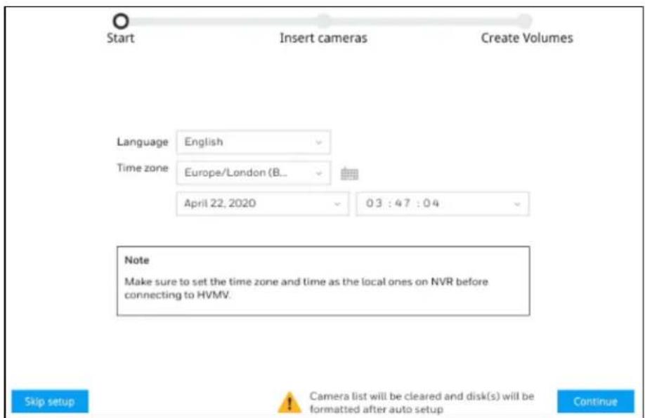
Select the language and time zone from the dropdown list and set date and time.
| Note | See Creating a Volume on page 54 to manually create the volume if you click Skip setup to skip this auto setup.After the hardware is reset, skipping setup is required to ensure the hard disk is not formatted. |
- Click Continue and cameras that have been searched within the LAN will be listed:
Figure 2-6 Device Initialization-Search for Cameras
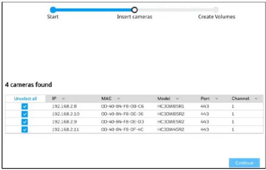
Note
-
This step will not be stayed for long if the cameras are accessed by default password.
• 30 series Camera FW version is V19.12.13 or later. -
Click Continue and the following windows is displayed:
Figure 2-7 Device Initialization-Insert Cameras
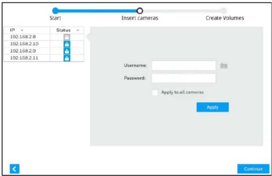
Enter the username and password of the camera.
- Click Continue and the following window is displayed:
Figure 2-8 Device Initialization-Creating Disks
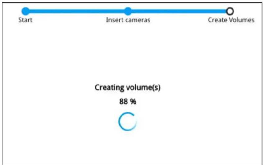
flowchart
graph LR
    A["Start"] --> B["Insert cameras"]
    B --> C["Create Volumes"]
    D["Creating volume(s)"] --> E["88 %"]
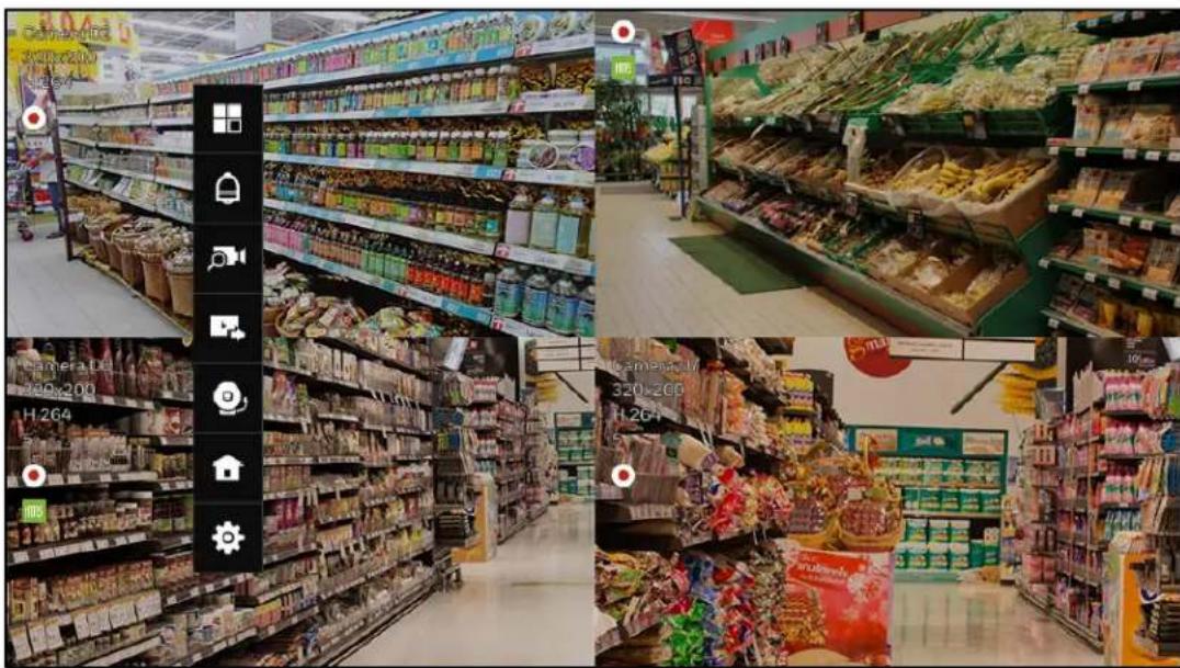
When the initialization is completed, the live view screen is displayed:
Figure 2-9 Live View Screen

3 Viewing Live Video
This chapter contains the following sections:
• About Live View on page 12.
• Live View Window on page 13.
- Toolbars on page 13.
- Shortcut Menu on page 15.
• Working with the PTZ Control Panel on page 16.
- Configuring PTZ Settings on page 17.
About Live View
Live view screen is the NVR's default screen. When the NVR is started, live video from the connected cameras is displayed on the screen. Change the window layout via 📄 on the main toolbar.
Figure 3-1 Live View Screen
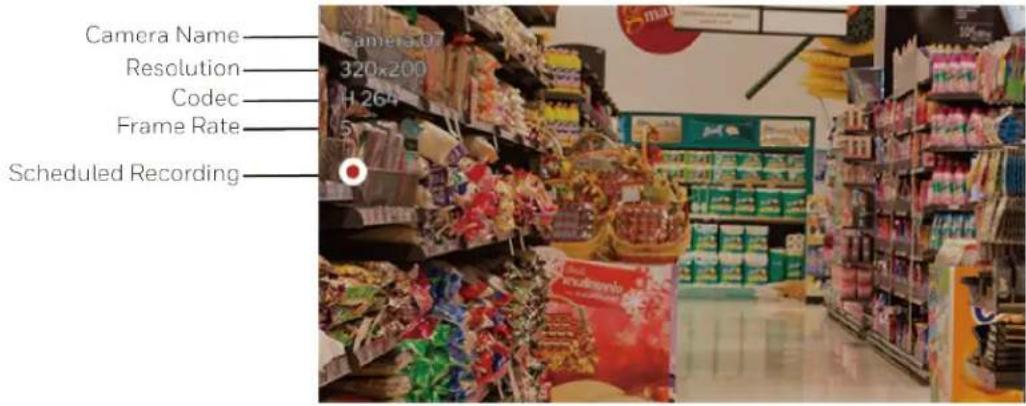
Live View Window
Figure 3-2
Toolbars
There are two toolbars (the main toolbar and the camera toolbar) that appear in front of the live view screen. Make sure a mouse is attached to your NVR. Move your mouse cursor on live view screen, and the Main Toolbar will appear. Click to select a view window, the Camera Toolbar will appear. Toolbars can be dragged to desirable place using mouse.
To hide the toolbar, right click the mouse on the window and deselect "Show toolbar".
Figure 3-3 Main Toolbar
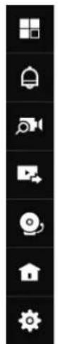
natural_image
Vertical toolbar with eight white icons on black background, no text or symbolsTable 3-1 Main Toolbar
| Icon | Name | Function |
| Layout | Select screen layout format and rotation. |


Alarm In/ Out Set the Alarm in /out.
Search Search for the recording clips.
Backup Export recordings.
Stop buzzer Stop buzzer.
Main Menu Open the main menu window.
Settings Open the settings interface.
Figure 3-4 Camera Toolbar

Table 3-2 Camera Toolbar
| Icon | Name | Function |
| Fisheye | Expand the fisheye display mode. | |
| PTZ | Expand the PTZ control panel. It is only activated with a camera that supports mechanical PTZ. | |
| Digital zoom | This applies when a camera is displaying the full of its field of view. Click it to zoom in on the field of view. | |
| Play recording clip | Search for the recording clips. | |
| Audio | Adjust the volume or mute the audio. | |
| Alarm In/ Out | Set the Alarm in /out. | |
| Snapshot | Click to take a snapshot from the camera currently selected.Note: this function only saves the snapshot (in JPEG) to a USB thumb drive. | |
| Manual recording | Click to start a manual recording from a selected camera. Click again to stop the recording. | |
| Deselect camera | Click to return to the Live View window. | |
| Note | Live view: if no management activities occur for a period, the tool bars disappear from screen. When in the idle mode, mouse cursor and tool bars will disappear. Moving the mouse cursor will re-activate the screen.Settings page: If left unattended for a period, system will automatically log out. The system will prompt for user credentials if a user tries to access the Settings page again.Search recording clips window: If currently there is a video playback, the system will not enter the idle mode. | |
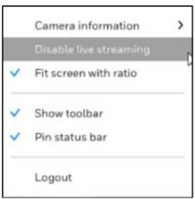
Shortcut Menu
The shortcut menu is displayed by right-clicking on the selected window.
Figure 3-5 Shortcut Menu
Working with the PTZ Control Panel (If applicable)
You can control a PTZ camera connected to the NVR through a network connection using the on-screen PTZ control panel on the camera tool bar.
PTZ Control Panel
Figure 3-6 PTZ Control Panel
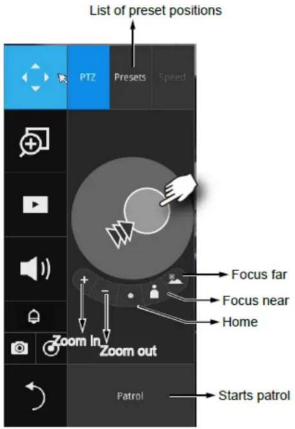
Table 3-3 PTZ Controls
| Name Function | |
| PTZ control | Click and drag the circle in the center towards the direction you wish to move to. |
| Focus | Click the Focus near and Focus far buttons to adjust camera focus. |
| Home | Click to move the camera lens towards the default home position. |
| Zoom | Use the Zoom in and Zoom out buttons to adjust the camera's zoom ratio. |
| Preset | If you configured preset positions, click this button, a list of preset positions will appear. |
| Patrol | If you configured preset positions into a patrolling tour, click this button and the camera will proceed with patrolling through preset points. |
Configuring PTZ Settings
You can configure presets, tours, patterns, and borders using the PTZ control panel.
Configuring PTZ Presets

Figure 3-7 PTZ Settings
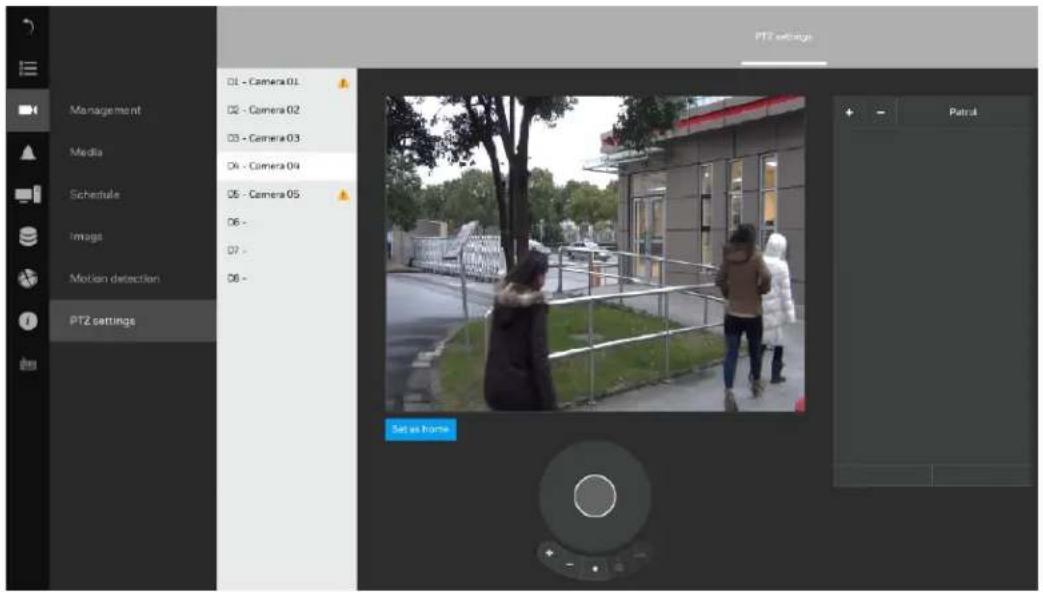
- Select a PTZ camera.
- Use the PTZ panel to move to a field of view where you want to designate as a preset position.
- Click +, and enter a name for the position. Press Enter to proceed.
- Repeat the configuration to create more positions.
- Click Apply for the configuration to take effect.
Note The PTZ panel can vary with different PTZ cameras.
4 Recording Video
This chapter contains the following sections:
• Manual Recording on page 18.
• Scheduled Recording on page 18.
Manual Recording
In live view window, select a window and click 📄 on the camera tool bar to start a manual recording. The manual recording icon 📋REC will appear on the window. Click 📄 again to stop the manual recording.
Scheduled Recording
By default, all video feeds from cameras are recorded at all time with the icon appeared on the window. You can modify the recording task using the schedule tool:
Go to → Schedule.
Figure 4-1 Scheduled Recording
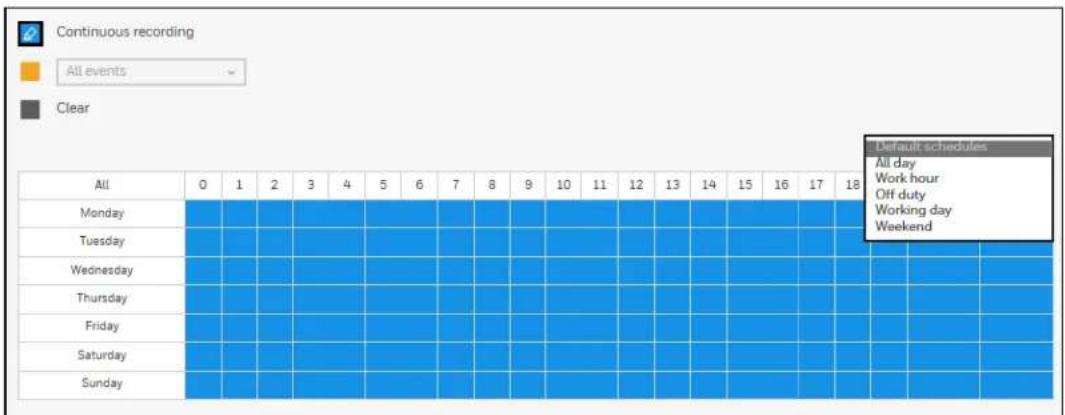
- Select a camera and click to select a recording condition's checkbox—Continuous recording, Event recording and Clear (no recording).
- Click and drag on the cells on the time table. For example, to stop the recording during a period, select the Clear checkbox and move the cursor across the time table. The minimum unit on the table is half an hour.
- You may also use the scheduler tool on the right to facilitate the process.
Figure 4-2 Scheduled Recording
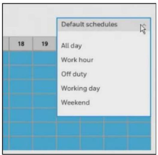
a) Select a condition checkbox, and then select the All day, Work hour, Off duty, Working day, Weekend options to apply a time selection.
| Note | Make sure to deselect the “All day” option before selecting the “Work hour”, “Off duty”, “Working day” and “Weekend” options. |
b) Repeat the process on individual cameras or click Apply to all cameras at the right bottom if the schedule can apply to all cameras.
- When the configuration is completed, click Apply.
5 Playing Back and Search Videos
This chapter contains the following sections:
- Playing Recording Clips on page 20.
• Searching Videos on page 21.
• Timeline Bar on page 23.
• Backing Up Video on page 24.
Playing Recording Clips
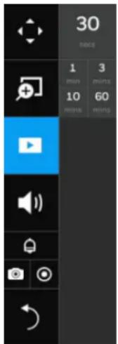
The Play Recording Clips function provides a shortcut to the latest recordings on the system. You can select 30 secs, 1 min, 3 mins, 10 mins, and 60 mins for an immediate playback.
- Select a camera and click 📋 on the camera toolbar and select a period you want to playback for.
Figure 5-1 Camera Toolbar-Playing Recording Clips
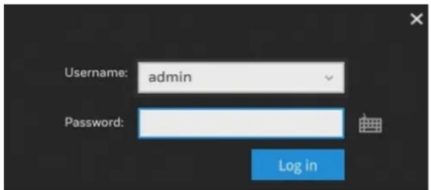
- A confirm window is displayed: (If left unattended for a period, system will automatically log out)
Figure 5-2 Credentials

- Enter the username and password. Click Log in and the playback interface is displayed:
Figure 5-3 Playback Interface
The playback begins from the point in time you selected, e.g., 30 seconds ago. This function allows you to quickly review what has just happened.
Searching Videos
- Click 📄 on the main toolbar and a confirm window is displayed: (If left unattended for a period, system will automatically log out)
Figure 5-4 Credentials
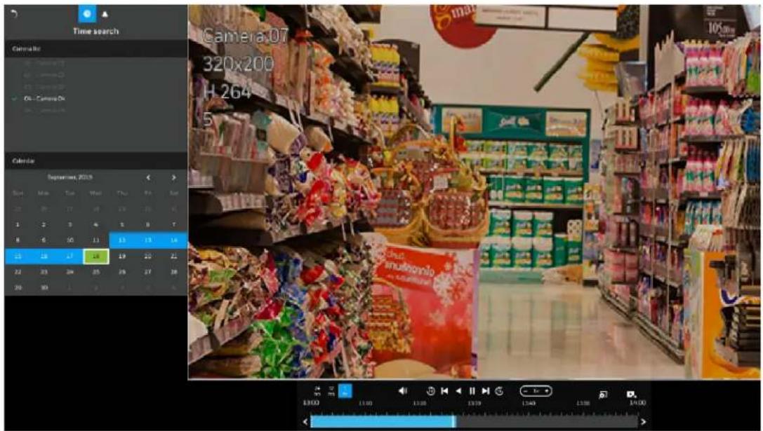
- Enter the username and password. Click Log in and the search interface is displayed:
Figure 5-5 Search
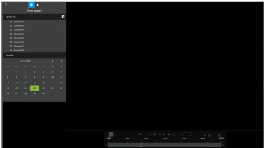
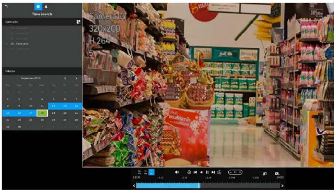
- Select cameras (up to 4 cameras) in the camera list and the days with recorded clips will be highlighted in blue. The date highlighted in green indicates today.
- Click to set up the layout when more than one cameras are played back simultaneously.
- Double-click on a day to begin playback and search.
Figure 5-6 Search and Playback
- Click the camera again to deselect it and select another one to playback if needed.
Note
- If a camera is deleted from the NVR, the recorded videos cannot be searched until it is added to the NVR.
- In case of four cameras playback simultaneously, the maximum resolution of each camera is 1080P.
Timeline Bar
By default, the playback starts from the beginning of a day's recording. While playing the recorded video, click on the timeline to replay a point in time in the video.
Figure 5-7

Table 5-1 Timeline Bar
Buttons Description
| 24hrs | Time scale selector. Use the buttons to select the span of time displayed on the tool bar. |
| Audio volume tuner. | |
| Play back from 10 seconds ago. (Suggest disabling the Dynamic Intra Frame period (DIF) setting (→→Media→Video) when perform this function as the time interval may not be 10 seconds while Dynamic Intra Frame period (DIF) is enabled.) | |
| Play back from 10 seconds after. (Suggest disabling the Dynamic Intra Frame period (DIF) setting (→→Media→Video) when perform this function as the time interval may not be 10 seconds while Dynamic Intra Frame period (DIF) is enabled.) | |
| Previous frame. (I-frame only) | |
| Next frame. (I-frame only) After you paused a playback, use this button to browse video frame by frame. | |
| Play backwards. | |
| Play. This button is available after you paused a playback. | |
| Pause | |
| Each click on it speeds down by 1/2. The slowest speed is 1/16. | |
| Each click on it speeds up by 2x. The fastest speed is 16 times. The current playback status is indicated on the screen. | |
| Digital zoom. This applies when a camera is displaying the full of its field of view. You can use the Digital zoom function to zoom in on the field of view. | |
| Export clips. Use this function to select a span of time you want to export to other medias. |
Backing Up Video
To Back Up Using the Playback Timeline Bar
Maximum 10 minutes of clips length for export via this method.
- Insert a USB storage device (such as a USB flash drive) into one of the USB ports on the NVR.
Figure 5-8 Backup Clips
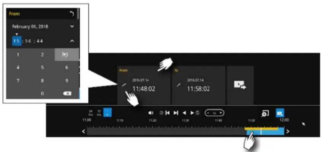
- Click on timeline bar.
- Select the "From time" by clicking on the timeline. You can also manually enter the "From time" and the "To time."
- Click the "From time" tab using a single click.
- Repeat steps 3 and 4 to configure the "To time".
- Click .
To Back Up Using the Main Tool Bar
The Export recordings button allows users to directly select a piece of recordings by a specific camera, and export that to a USB thumb drive. Users can select one or multiple cameras, select a period in which the recording took place, and then click Export.
The maximum length of recording export is 24 hours.
- Insert a USB storage device (such as a USB flash drive) into one of the USB ports on the NVR.
- Click 📋 on main tool bar and the following window is displayed:
Figure 5-9 Backup Video
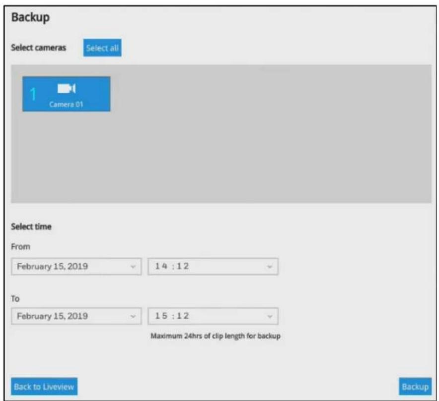
- Select one or multiple cameras from the camera list.
- Select the start time of the period of recording time and the end time of the period of recoding time.
- Click Backup.
6 Settings
This chapter contains the following sections:
• Setting-Camera-Management on page 27.
• Setting-Camera- on page 35
• Setting-Camera-Media on page 32.
- Setting-Camera-Image on page 38.
- Setting-Camera-Motion Detection on page 39.
• Setting-Camera-PTZ settings on page 40.
- Setting-Event-Event on page 41.
• Setting-Event-Email on page 46.
• Setting-System-Information on page 47.
• Setting-System-Maintenance on page 48.
• Setting-System-Display on page 50.
• Setting-System-Log on page 51.
• Setting-User on page 51.
- Setting-Storage on page 54.
- Settings-Network-IP on page 57.
- Settings-Network-Service on page 58.
• Settings-Network-P2P on page 59.
Setting-Camera-Management
Change Password
Go to → Management→Add/edit.
Figure 6-1 Management
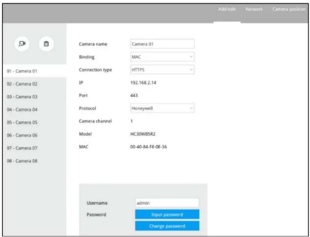
1. Click Change Password.
Figure 6-2 Set New Password
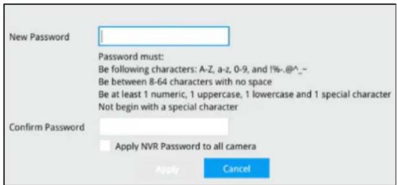
- Input the new password and confirm it.
- Click Apply.
Note
Camera's password can only be changed at local client, not available at web client.
Adding a Camera

- Click and a list of cameras in the same subnet will appear:
Figure 6-3 Adding a Camera
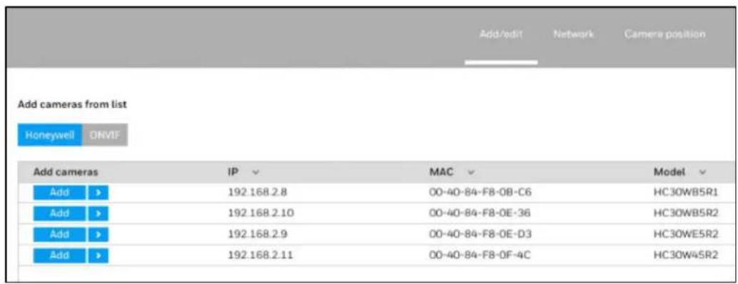
- Click Honeywell or ONVIF to select the camera protocol.
| Note | 30 series cameras that support the Honeywell protocol: | |||
| HC30W42R3 | HC30W45R3 | HC30W45R2 | HC30WB2R1 HC30WB5R1 | |
| HC30WB5R2 | HC30WE2R3 | HC30WE5R3 | HC30WE5R2 HC30WF5R1 | |
| HC60W35R2 | HC60W35R4 | HC60W45R2 | HC60W45R4 HC60WB5R2 | |
| HC60WB5R5 | HC60WZ2E30 | |||
- Click Add and the camera will be placed at an unoccupied position. You may also expand the menu on the side of the Add button to select a position number.
- When a camera is added, it should appear on the graphical placement below.
- Click Apply after you added cameras.
- You may click to return to the previous window.
Removing a Camera

- Click and the remove button will turn yellow.
Figure 6-4 Removing a Camera
- Mouse over to the camera you want to remove, and its entry will display the Remove message.
- Click the Remove message and a confirm window prompted:
Figure 6-5 Confirm Message
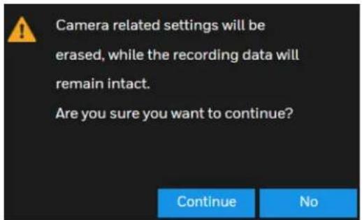
- Click Continue to remove the camera.
Network
Go to → → Management→Network.
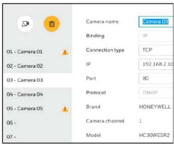
Here you can configure the network type, IP address, and the connection ports for video streaming.
Figure 6-6 Camera Network
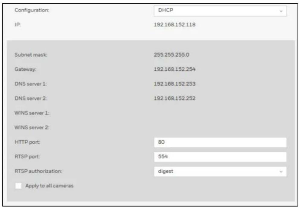
You can select DHCP as the method for cameras to acquire IP addresses, or you can manually configure static IPs for a single or all cameras.
It is usually not necessary to change port numbers for the HTTP and RTSP ports unless there is a conflict in your network environment.
Camera Position
Go to → → Management→Camera position.
Figure 6-7 Edit Camera Position
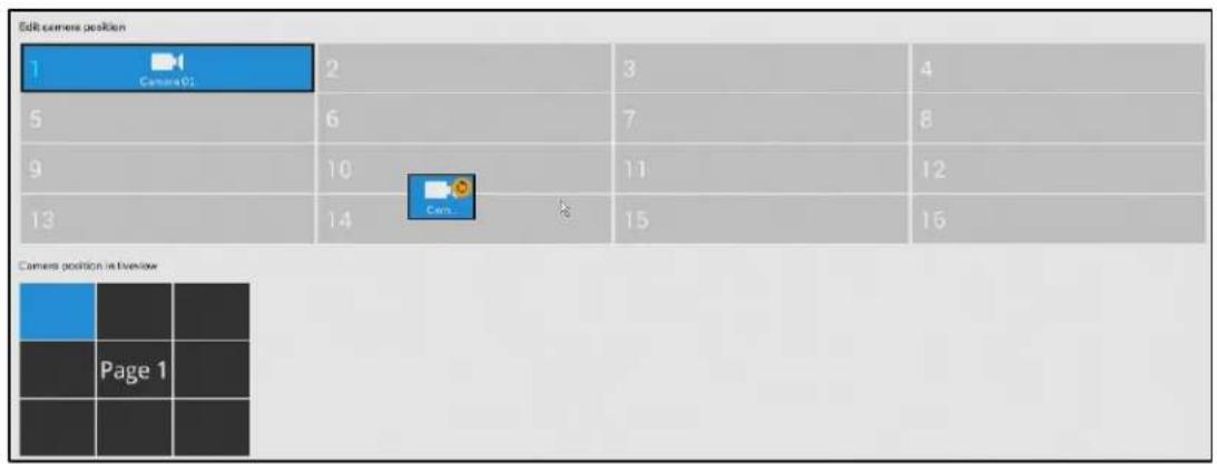
To change a camera's position on the Liveview layout, click and drag a camera to a desired position. Click Apply for the configuration change to take effect. The position screen displays the current layout on the Liveview screen.
Setting-Camera-Media
Stream Management

flowchart
graph LR
    A["Go to"] --> B["→"]
    B --> C["→Media→Stream management"]
Figure 6-8 Media-Stream Management-Live
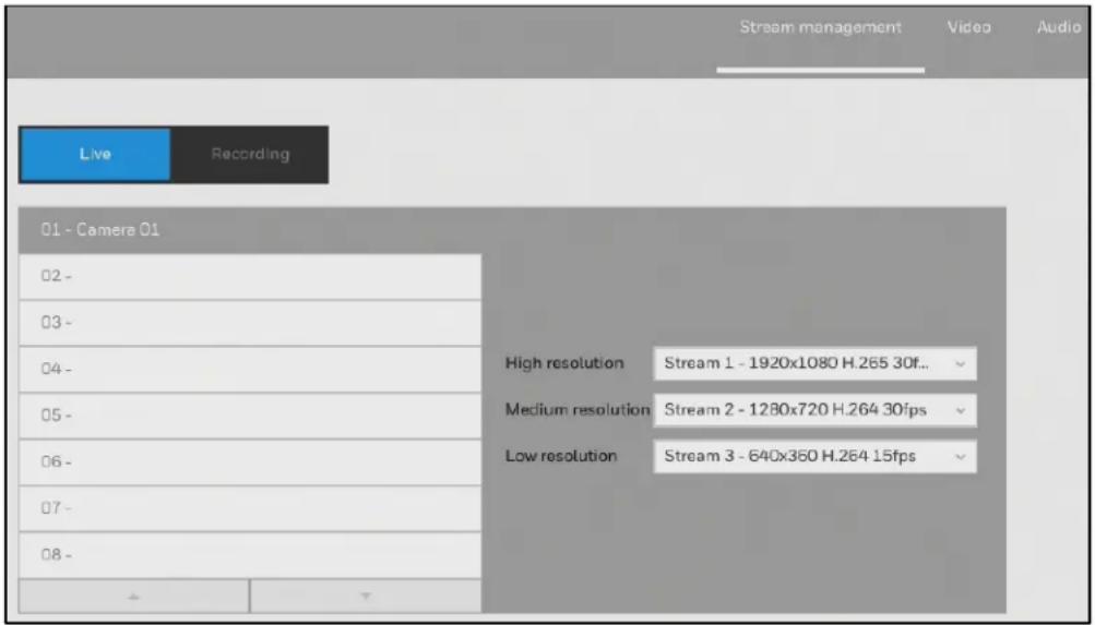
Click Live and you can manually select High, Medium, or Low resolution streams from the pre-configured video streams of a camera for live view.
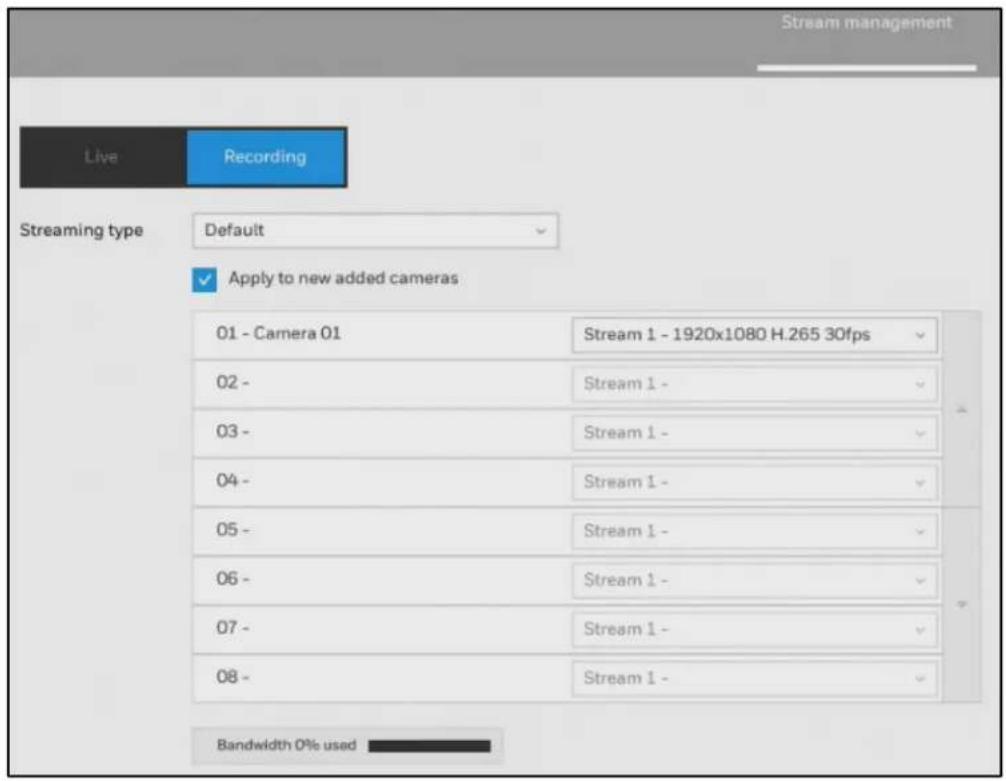
Figure 6-9 Media-Stream Management-Recording
Note
Select MJPEG as codec and the maximum size of the frame size is 1920*1920.
Click Recording and you can use these preset conditions to configure the resolution, image quality, frame rate, and the bandwidth consumption of the recording stream on this window.
Figure 6-10 Streaming Type
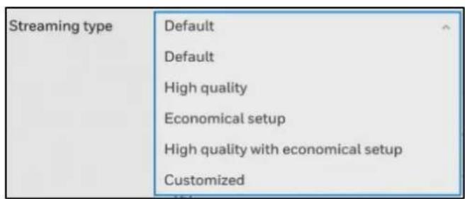
Table 6-1 Recording Stream Type
| Recommended setting | Configuration |
| Default | Medium resolution; full frame rate. |
| High Quality | Guaranteed video quality set as Good; full frame rate. |
| Economical setup | Medium to low resolution; frame rate at 5fps. |
| High quality with economical setup | High resolution, Good image quality; frame rate at 5fps. |
With each recommended configuration applied, the estimated bandwidth consumption value is immediately calculated and displayed at the lower screen.
Click Apply for the configuration change to take effect.
Video

Figure 6-11 Media-Video
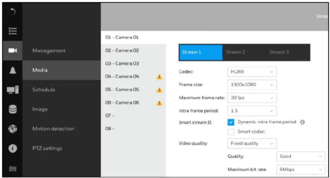
The Video window allows you to configure all video streams (the no. of stream available can be different for different models). You can configure the following:
Codec: video compression codec in H.264, H265 or MJPEG.
Frame size: video resolution.
Maximum frame rate: the highest frame rate.
Intra frame period: how often an I-frame will be inserted into the video stream.
Smart Stream II: some newer camera models come with Smart Stream features. Please refer to the next page for detailed information.
Video quality: you may either select Constant bit rate or Fixed quality as the defining rules for video transmission:
Table 6-2 Video Quality
| Constant bit rate | Places a packet size threshold on video frames; This guarantees the frame rate per second performance, yet image quality can be compromised if bandwidth is not sufficient in your network environment. |
| Fixed quality | Guaranteed video quality, and to ensure image quality, some frames may be dropped when bandwidth is not sufficient. |
When the configuration is completed, click Apply.
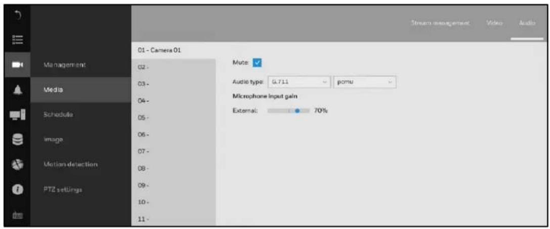
Audio

The Audio window allows you to configure all audio codec, sampling rate, and Microphone input gains. Depending on design of the camera models, some codecs may not be available. Also, there are cameras that come without embedded microphones.
Figure 6-12 Audio
Setting-Camera-Schedule
Recording Options
Go to → Schedule→Recording options.
Figure 6-13 Recording Options
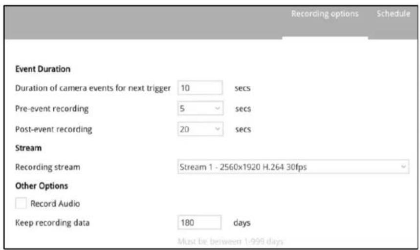
On the Recording options page, you can configure the following:
Event Duration: Configure the duration of camera events, for the concern that camera can be too frequently triggered.
Pre-event recording/ Post-event recording: Enter the Pre-and Post-event recording time. The triggering events can be DI, DO, Motion detection, PIR, or Tampering detection. A recording length of 10 seconds of pre-event and up to 300 seconds of post-event can be configured.
Stream: The default recording stream is Stream 1, and the system automatically adjusts the frame rate, resolution, etc. for optimum performance. However, you can still change the streaming characteristics. Note that you cannot assign the recording task to other video stream.
Other options: Enable or disable audio recording. Note that audio transmission through HDMI cable is currently not available. Change the life expectancy of the recording data.
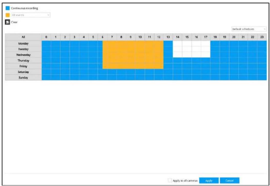
Schedule

Figure 6-14 Schedule
bar
| Day | Continuous recording | All events | |---|---|---| | All | 0 | 1 | | Monday | 0 | 0 | | Tuesday | 0 | 0 | | Wednesday | 0 | 0 | | Thursday | 0 | 0 | | Friday | 0 | 0 | | Saturday | 0 | 0 | | Sunday | 0 | 0 |Note
By default, all video feeds from cameras are recorded at all time (highlighted in blue).
You can modify the recording task using the schedule tool:
- Select a camera and click to select a recording condition's checkbox—Continuous recording, Event recording and Clear (no recording).
- Click and drag on the cells on the time table. For example, to stop the recording during a period, select the Clear checkbox and move the cursor across the time table. The minimum unit on the table is half an hour.
-
You may also use the scheduler tool on the right to facilitate the process.
a. Select a condition checkbox, and then select the All day, Work hour, Off duty, Working day, Weekend options to apply a time selection.
b. Repeat the process on individual cameras or select the Apply to all cameras if the schedule can apply to all cameras. -
When the configuration is completed, click Apply.
Note
Event-triggered recording and continuous recording cannot be taking place at the same time.
Setting-Camera-Image
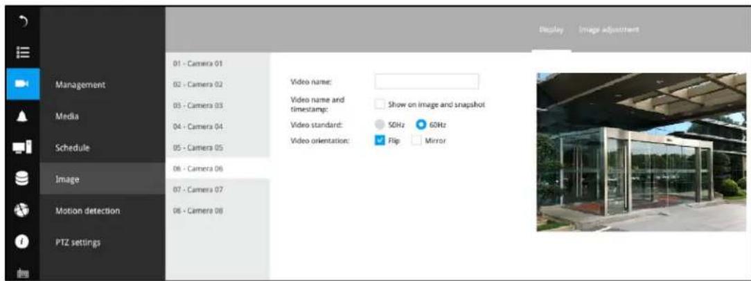
Display

Figure 6-15 Image-Display
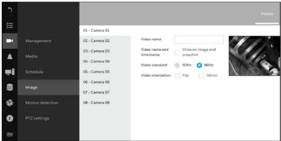
The Display window allows users to tune the image display options:
Video name: The video name is displayed on the title bar that is displayed on each view cell. The screen shot below shows a name as "Speed dome."
Video name and timestamp: Default is enabled. If enabled, the video name and time is displayed on the view cell.
Video Standard: Depending on power line frequency of your country, select a matching option, NTSC 60Hz or PAL 50Hz, to avoid image flickering due to unmatched electricity.
Video orientation: Select these options if the image from camera needs to be vertically or horizontally flipped.
Click Restore to poll for the original settings or click Apply to finish the process.
Image Adjustment

flowchart
graph LR
    A["Go to"] --> B["→ Image"]
    B --> C["→ Image Adjustment"]
Figure 6-16 Image-Adjustment
The Image adjustment window allows users to tune the basics about image display options:
- Color
- Brightness
- Saturation
- Contrast
- Sharpness
High TV line, Gamma curve, low light compensation, etc. The rest of the options depend on the lens and image sensor type of each individual camera. Therefore, the options here can vary. For unique options coming with each individual camera, please refer to their User Manuals for more information.
Click Restore to poll for the original settings or click Apply to finish the process. For features common among cameras, you may select the Apply to all cameras checkbox.
Setting-Camera-Motion Detection
The Motion detection page allows you to set up a motion detection area.

Figure 6-17 Motion Detection

Note Up to 5 ROI windows can be created for a camera.
To set up a detection window:
- Select a camera by a single click in the camera list.
- Click and drag to draw a rectangular detection window.
- Pull the detection area level up to a preferred position. An object must be larger than the detection area to trigger an alarm.
- Select a Sensitivity level using the slide bar.
- Click Apply for the configuration to take effect.
Setting-Camera-PTZ settings
Please see Configuring PTZ Settings on page 17.
Setting-Event-Event
The events reported from individual cameras' alarm in /alarm out, and motion detection can be accommodated in the NVR system's alarm settings. These events will then be reported or trigger corresponding actions as follows:
• Record the video by the time the event is triggered.
• Reporting events via Email with snapshots attached.
• Sound the onboard buzzer.
- Triggering video snapshot and text message by the occurrences of events to an FTP site.
- Triggering a camera's alarm out.
- Triggering a PTZ camera(s) for its lens to move to a preset position.
- Sending notification to the HVMV for MS Window software.
- Sending a full screen live view on the connected monitor.
When an alarm is triggered, a message prompt will appear on the Liveview or any configuration window.
Figure 6-18 Event

Creating an Event

1. Click + and the following window is displayed:
Figure 6-19 Create a New Event-Status
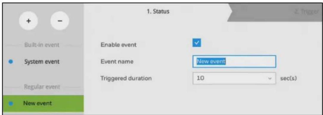
- Manually enter a name. Up to 16 numeric or alphabetic characters is supported for the name, including symbols such as [0-9] [a-z] [A-Z] [_]. And then designate the interval
between one alarm and the next triggered alarm to avoid the situation that the alarms can be too frequently triggered. Click ▶ and the following window is displayed:
Figure 6-20 Create a New Event-Trigger
| Built-in event | Select triggers | |
| ✓ System ✓ 01 - Camera 01 ✓ 02 - Camera 02 03 - Camera 03 04 - Camera 04 05 - Camera 05 06 - Camera 06 07 - Camera 07 ✓ 08 - Camera 08 | ✓ Camera Alarm In ✓ Camera Alarm Out ✓ Motion detection ✓ People detection ✓ Intrusion detection ✓ Tampering detection ✓ Camera disconnected | |
| • System event | ||
| Regular event | ||
| • New event | ||
| Selected | ||
| System | System Alarm In, System Alarm Out, Disk failure, Disk full | |
| 01 - Camera 01 | Motion detection, People detection, Intrusion detection, Tampering detection, Camera disconnected | |
| 02 - Camera 02 | Motion detection, People detection, Intrusion detection, Tampering detection, Camera disconnected | |
| 08 - Camera 08 | Motion detection, People detection, Intrusion detection, Tampering detection, Camera disconnected | |
- Select system triggering conditions, or one or more cameras by selecting their checkboxes. Click ▶ and the following window is displayed:
Figure 6-21 Create a New Event-Action
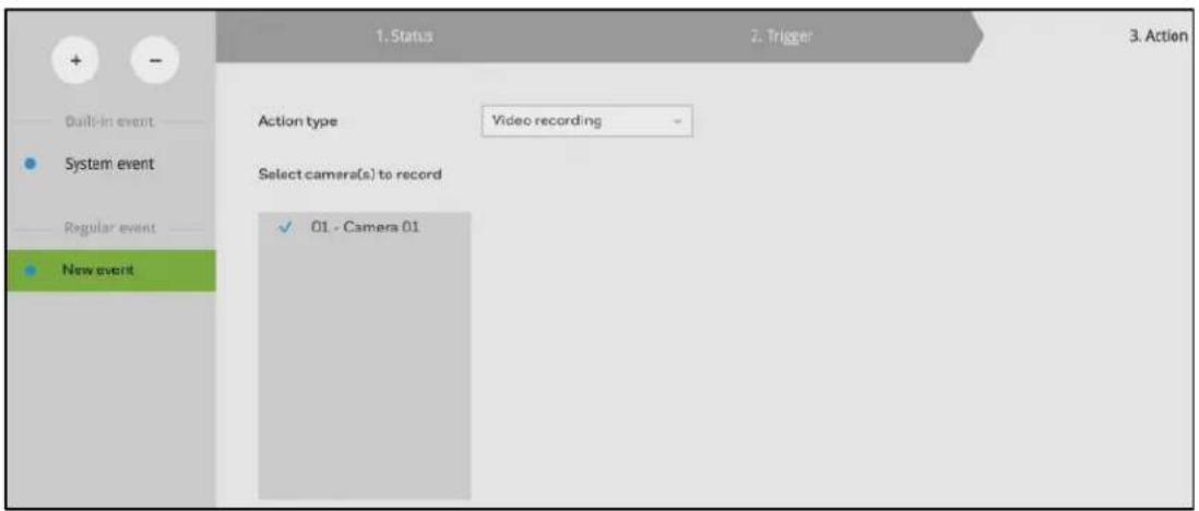
- Select the Action type from a drop-down menu which includes:
Video recording - When an event is triggered, the selected camera will record a video footage of the length defined by the pre-/post-event setting, to the NVR system.
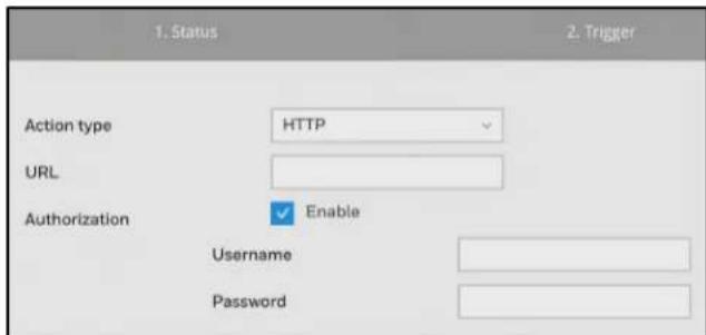
Send email – When an event is triggered, it sends an Email to the administrator along with a snapshot of the event.
Figure 6-22 Email Setup
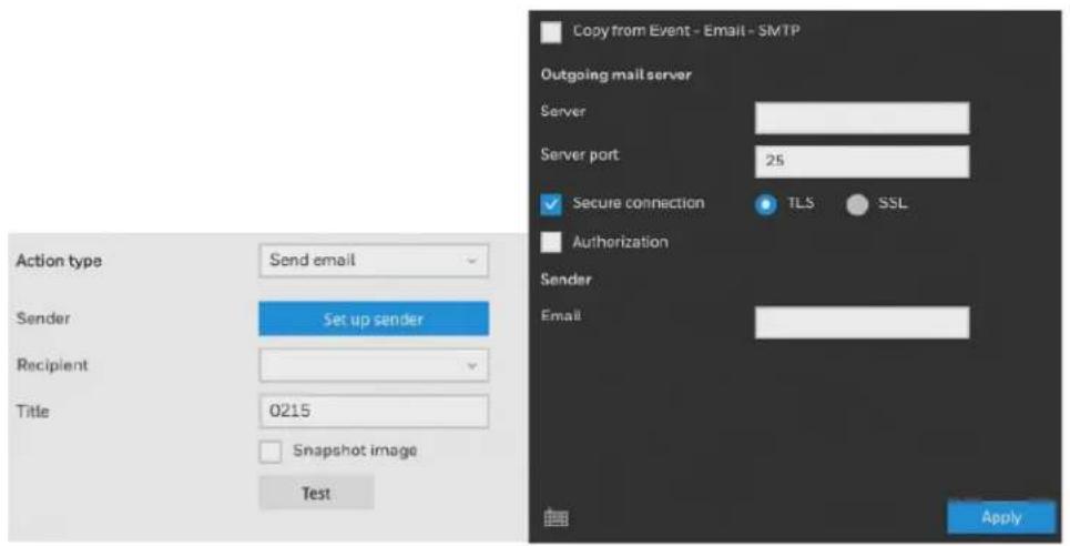
To configure Email notification, enter valid Email addresses as the Sender and Recipient addresses, an Email subject, and the SMTP server address through which the Email will be delivered. If you need to log in to SMTP server to deliver an Email, enter the User name and password for access to that account.
| Note | The Email subject and addresses can be composed of 254 characters in numeric or alphabetic characters including: [0-9] [a-z] [A-Z] [_][ ][-][.][.][@]. You can enter the addresses of multiple recipients. Use semicolons, (;), to separate the addresses of multiple recipients. |
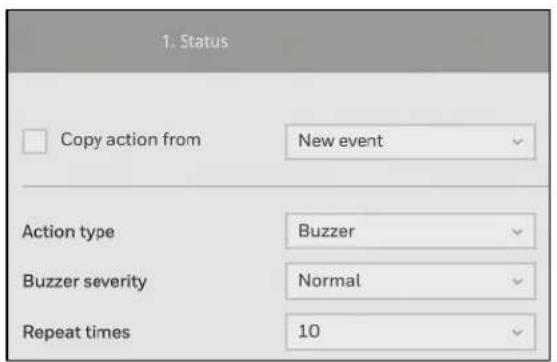
Buzzer - The buzzer is sounded on the occurrence of the event. The buzzer tones are categorized into: Critical (1 long, 1 sec interval) Major (1 long 2 shorts, 1 sec interval), Normal (3 shorts, 2 sec interval), Minor (2 shorts, 2 sec interval), and Notify (2 very shorts) depending on the importance of an event. Select a Buzzer modulation from the drop-down list.
A long tone has a duration of 1 second, while a short tone 0.5 second. A very short tone lasts only for 0.1 second.
Select how many times the buzzer tones will be repeated on the occurrence of an event.
Figure 6-23 Buzzer Options
If events of different importance are issued at the same time, e.g., one major and one minor event, system will ignore the minor event and sound the buzzer tone for the major
event only. The buzzer can be sounded either by the Alarm actions or the system events. If Alarm actions and system service events occur at the time, Alarm actions have the higher priority.
If multiple Alarm actions occur, the currently-sounded events can be depleted by the new event.
There are conditions that the system will sound the buzzer, and the conditions are not configurable.
- Disk failure - missing drives or SMART detected failures.
- Disk full – the free space is too small for recording tasks.
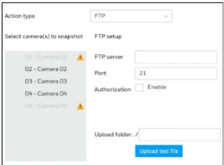
FTP-Snapshots from specified cameras can be uploaded to an FTP site on the occurrence of an event. Enter the FTP site address in the dotted-decimal notation, e.g., 159.22.151.20. Enter the login name and password for the user account. You can enter a directory name you prefer on the FTP site. The server port default is 21, a different number between 1025 and 65535 can also be assigned.
The snapshot thus delivered has a size of 320x240 pixels. If authentication is not applied, login will proceed using the [anonymous] account. The file names of the snapshot jpeg. files will look like this: [MAC]_[DATE]_[TIME]_[CAMERA_INDEX].jpg - If similar files already exist, an additional index number will be added to the end of file name.
Figure 6-24 FTP Setup
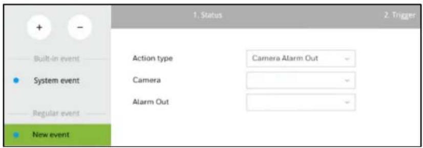
Camera Alarm Out - A triggered alarm triggers a camera's alarm out, e.g., an alarm siren.
Figure 6-25 Camera Alarm Out Setup
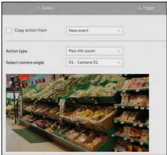
Pan-tilt-zoom - A PTZ capable camera can move its lens to the preset position in case of a triggered alarm. For example, a triggered sensor may indicate an area of interest has been intruded, and a camera's field of view should be moved to cover that area. The precondition is that you properly set up preset positions on your PTZ cameras using a local or a web console.
Figure 6-26 Pan-tilt-zoom setup
HTTP - Select to send the media files to an HTTP server when a trigger is activated.
Figure 6-27 HTTP Setup
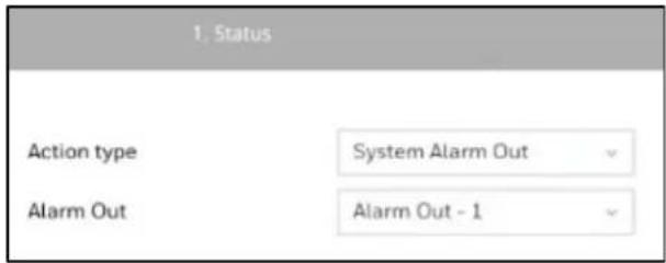
System Alarm Out - A triggered alarm can be used to toggle the NVR's alarm out, e.g., to sound an alarm siren.
Figure 6-28 System Alarm Out
Send to HVMV—An event message will display on your HVMV software. (An event should be first setup in HVMV and select Sound the event as action.)
- Click ▶ and the following window is displayed:
Figure 6-29 Event Schedule
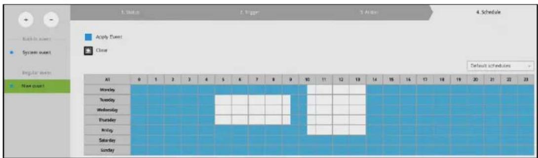
- Click and drag the mouse to activate or de-activate alarm triggers throughout a specific timeline.
- Click Finish to end the configuration.
- Repeat the process above to create more alarms according to the needs in your surveillance deployment.
Removing an Event
- Click - in and the remove button will turn yellow -
- Mouse over to the event you want to remove, and its entry will display the Remove message.
- Click the Remove message.
Setting-Event-Email
This page provides an interface where you can configure the connection to a Mail server. via the Mail server, the system can deliver Emails containing system alarm messages to multiple
receivers. A reachable Mail server and Email accounts must be provided before you can apply the settings.

The configuration options are identical to those found in the Email configuration in Settings - Event window. See Email Setup on page 43.
On this window, you can configure the following:
- Change the system name. Using a name in different languages is supported via a web console.
- Select the UI text language.
- Configure system time, time zone, and if you are connected to a DNS server where Auto Daylight Saving time can be applied, you can acquire the associated setting from a server
within your network. You can use the Auto Setup button to automatically update the daylight-saving configuration. A system reboot is required.
- Manually update the daylight-saving profile in the GZ format using the Import file button below.
Click Apply for the configuration to take effect.
| Note | If the NTP time server configuration (Auto) is preferred, the system will automatically configure all cameras to be listening to the system, and therefore to the same time server. |
Setting-System-Maintenance

Figure 6-31 Maintenance
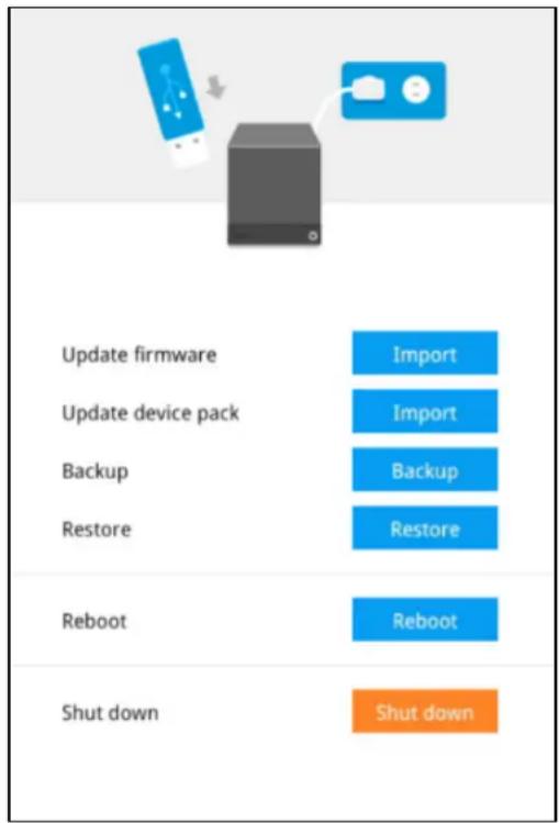
On this window, you can perform 4 maintenance tasks:
- Update firmware –Download firmware and save it to a USB drive in the FAT format, attach the USB device to the NVR for firmware upgrade.
- Update device pack-A device pack allows you to import associated configurations and parameters for new camera models so that these cameras can be integrated into your NVR configuration. The information in the device pack is related to some tunable parameters.
- Backup – You can back up your system configuration using the Backup function. Click Backup, a message window will prompt. Click Save to preserve your system configurations.
Select a location for your backup file, then click Save to complete the process. If you back up to a USB thumb drive, that thumb drive must be formatted using the FAT format.
Note
The backup action does not involve the following:
- Recorded videos and database.
- Alarm records
- Restore—If you have a previously-saved profile, you can restore your previous configuration. Click Restore. A file location window will prompt. Locate the backup file and click Open. The Restore process will take several minutes to complete, and system operation will be interrupted during the process.
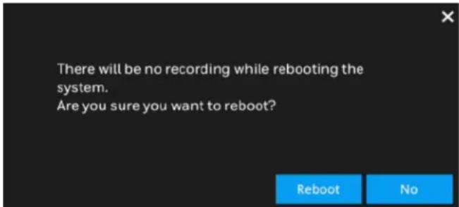
- Reboot – Click the button to reboot NVR.
Figure 6-32 Reboot
- Shutdown – Click the button to shutdown NVR.
Figure 6-33 Shutdown

Refer to the following table for detailed information on compatible USBs.
Table 6-3 Compatible USB Table
| Brand Specification | |
| Transcend | TS8GJF370 8GB, USB2.0, Pen Drive, Classic, White |
| SanDisk | SDCZ73-032G-G46, SanDisk Ultra Flair USB 3.0 32GB |
| SDCZ600-032G-G35, SanDisk Cruzer Glide 3.0 32GB | |
| Sony | USM16GL, microvault USB2.0 16GB |
On this page, you can configure the system to consecutively display (rotate) cameras' view cells on the Liveview window. For example, if you have 8 cameras in 2 2x2 layouts, the rotation can let you see the live views of all cameras by every few seconds.
To enable the rotate function, click on the layout panel.
Figure 6-35 Layout
Setting-System-Log
Go to → → Log.
System logs are categorized as System, Recording, User, and Error. You can search for past logs in each category window by selecting a range of time and clicking Search
Figure 6-36 Log

Setting-User
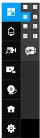
Go to → →User.
Figure 6-37 User
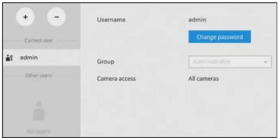
The User page allows you to create more users, to change user password, and place limitations on users' privileges and administration rights. Up to 16 users can be created, including the default administrator.
By default, there are two user groups: Administrator and Regular user.
- The administrator users can access all cameras recruited in the configuration; while the regular users can be configured to have access to some or all cameras.
- The regular users cannot access the Settings window, meaning that regular users cannot add or remove cameras, make changes to alarm, network, and all other system settings. When users try to access the Settings window, the login window prohibits regular users to log in.
The system blocks out the video feeds from users who are denied of the access to particular cameras. The alarms and the alarm-triggered recordings from those cameras will also be inaccessible for unauthorized users.
| Note | The default name and password for administrator group are admin and admin. It is highly recommended to change the default password to prevent unauthorized access to the system. |
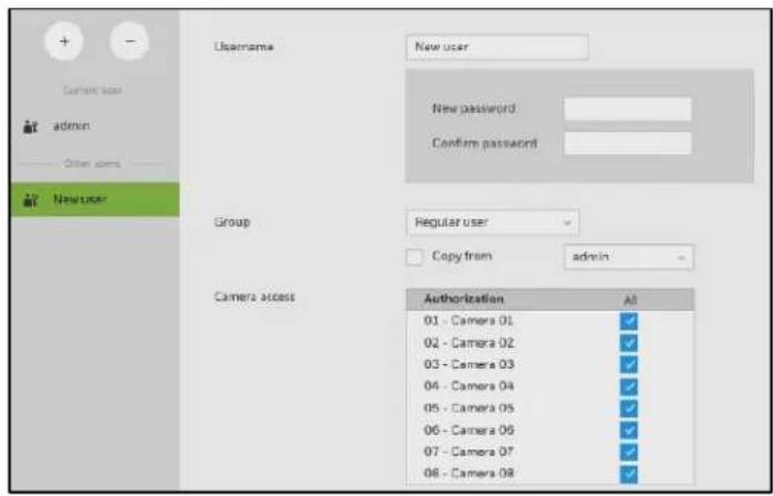
Creating a User
- Click + in Figure 6-36 and the following window is displayed:
Figure 6-38 Create a User
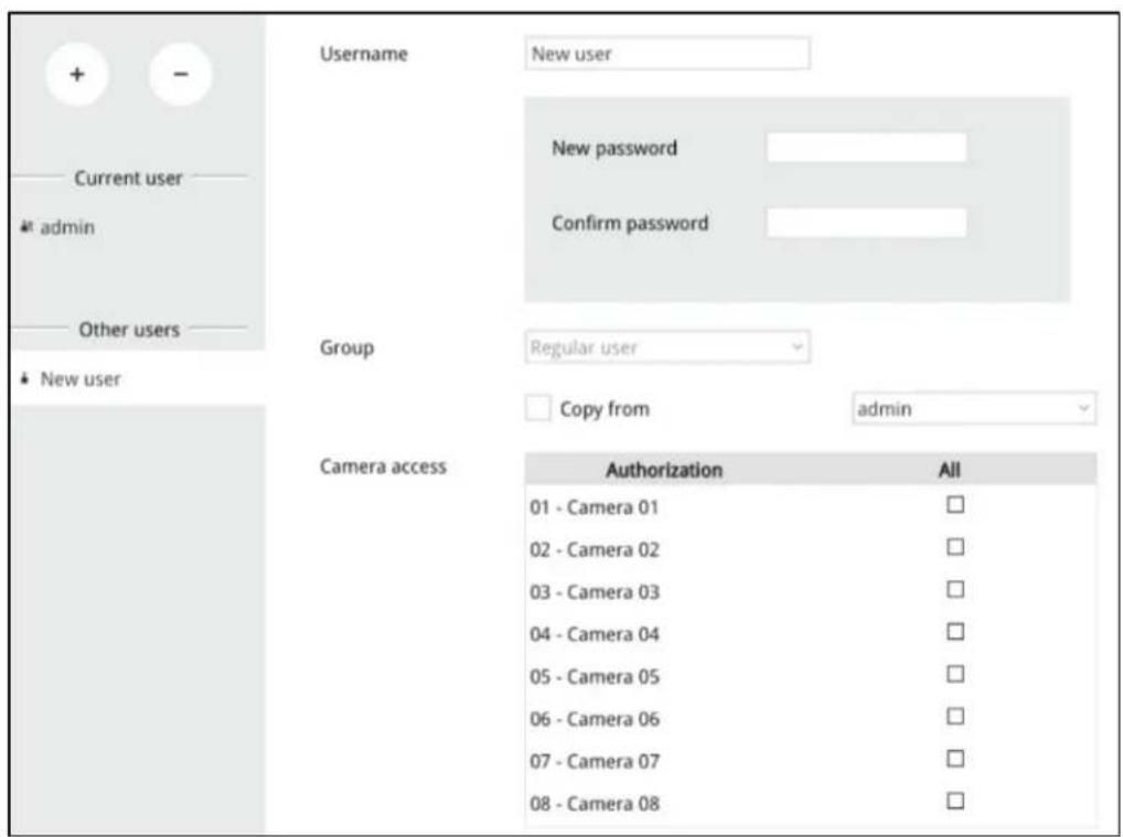
-
Enter user name, password and select a group from the dropdown menu.
-
The maximum number of characters for a user name is 64, with alphabetic and numeric characters including [0-9] [a-z] [A-Z] [_] [ ] [-] [,][@]. The maximum number for password is also 64.
- If you are creating a regular user with limited access to cameras, deselect the checkboxes by the cameras to deny the user access.
Note
- Click Apply to close the configuration window. Repeat the process to create more users.
Removing a User
- Click - in Figure 6-36 and the remove button will turn yellow
- Mouse over to the user you want to remove, and its entry will display the Remove message.
- Click on the Remove message.
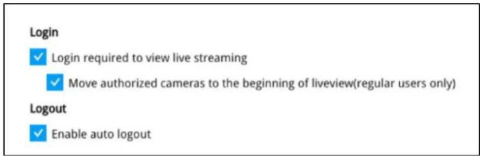
Setting-Login/Logout
Go to →→User.
Select related settings of login/logout.
Figure 6-39 Login/Logout
Setting-Storage
Creating a Volume
Before creating the volume, make sure the HDDs have been properly installed.
Go to → Storage.
Figure 6-40 Setting-Storage
- Click 📄+ and the following window is displayed:
Figure 6-41 Select Disk
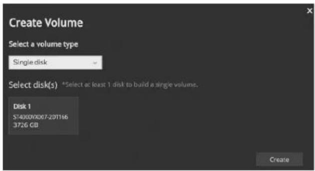
- Click a disk that you want to use and click Create. A confirm message prompted as below:
Figure 6-42 Confirm
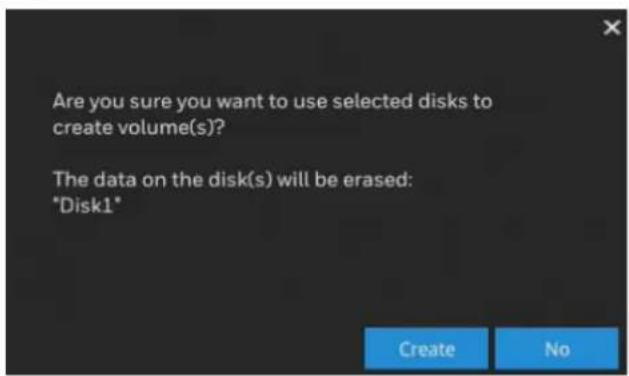
- Click Create to proceed.
Figure 6-43 Creating Volume
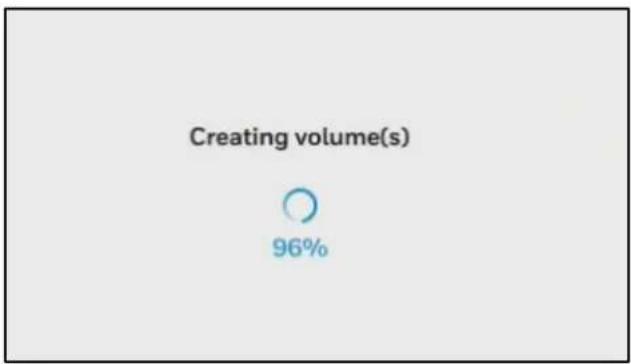
pie
Creating volume(s) | Category | Volume (s) (%) | | :--- | :--- | | Selected | 96 |When the creating is completed, the following window is displayed:
Figure 6-44 Volume
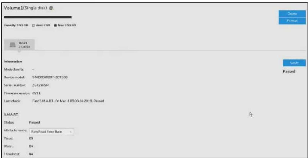
Repeat the above steps to create a new volume when you installed another disk.
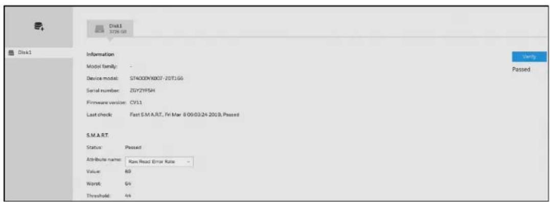
The storage page displays the volume information including physical position, total capacity, used and free space, and associated commands such as Format and Delete. Since each volume contains only 1 hard drive, detailed information about the hard drive is also displayed on this page.
You can format an existing storage volume in situations such as when you need to re-deploy the system elsewhere.
Disk Information
Model family: The brand name of the HDD manufacturer.
Device model: The disk model name.
Serial number: Serial number assigned to the disk drive.
Firmware version: The version of firmware running on this disk drive.
Last check: The bad block check or S.M.A.R.T. test previously executed on this drive.
Status: S.M.A.R.T. status polled from the disk drive. This is not the results from a manually-executed S.M.A.R.T. test.
Attribute name: The various attributes can vary from different HDD manufacturers. Value: Value for the currently selected attribute.
Worst: Worst value acquired for that attribute.
Threshold: A predefined threshold or triggering value. The threshold below which the normalized value will be considered exceeding specifications.
Raw value: The detected parameters for that attribute.
Status: The judgement made to deem the current reading as OK or failed.
Verify
Click Verify on Figure 6-42 to check the disk status. Three types of check disk actions can be initiated through this button.
Bad block: Performs read/write test to drive sectors to locate bad blocks. This action may take several hours to complete.
Fast S.M.A.R.T.: Tests the electronic and mechanical performance and disk read performance, including those on disk buffer, read head, seek time, and integrity of drive sectors. The short test is performed on a small section of disk platters, and takes about 2 minutes to complete.
S.M.A.R.T.: The long test is more thoroughly and is performed to all drive sectors. The actual completion time depends on drive sizes and the attributes put to test.
The Check disk functions mentioned above, when performed during active I/Os, can consume system resources and cause dropped frames with the recording tasks.
| Note | Disk verify function requires a volume to be temporarily disabled; namely, the video recording will be stopped before disk verify can be performed. |
Settings-Network-IP

Figure 6-45 IP
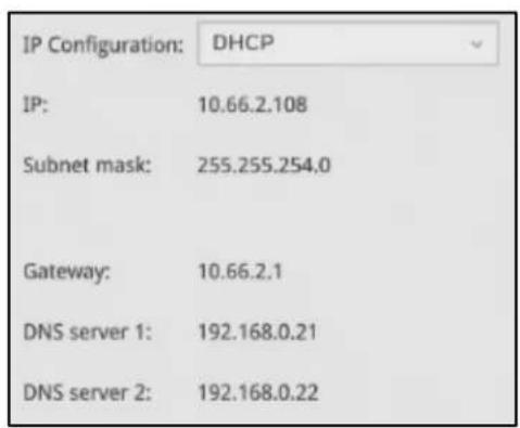
DHCP: Default is selected, the server obtains an available dynamic IP address assigned by the DHCP server each time the system is connected to the LAN.
Manual setup: Select this option to manually assign a static IP address to the NVR. Enter the Static IP, Subnet mask, Default router, and Primary DNS provided by your ISP.
Subnet mask: This is used to determine if the destination is in the same subnet. The default value is "255.255.255.0".
Default router: This is the gateway used to forward frames to destinations in a different subnet. Invalid router setting will fail the transmission to destinations in different subnet.
Primary DNS: The primary domain name server that translates hostnames into IP addresses.
Secondary DNS: Secondary domain name server that backups the Primary DNS.
When finished with the network settings, click Apply.
Settings-Network-Service

Figure 6-46 Service
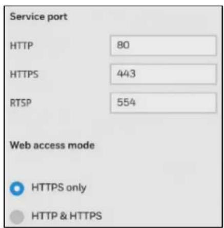
By default, the NVR service and video streaming are accessed via HTTP port 80 and RTSP port 554. You can designate a different port number if the need arises. Usually it is not necessary to change these ports. HTTPS encrypted connection is enabled by default.
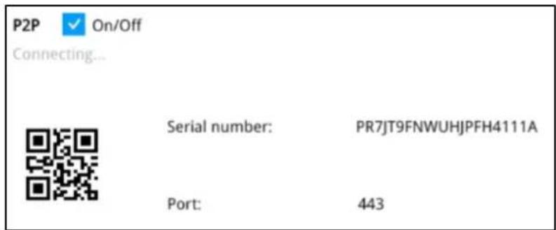
Settings-Network-P2P
You can easily connect to the unit using a mobile device with the HVMV APP using the P2P screen. To use this option, you will need the HVMV APP downloaded, installed, and have registered/created an account. When the APP is setup, go to Device Management→P2P and use the camera to view the QR code on the P2P screen. The device's information and connection will automatically be downloaded to the APP and you can now connect to the NVR using your mobile device.

Click to enable this option.
Figure 6-47 P2P Setting
7 Management over a Web Console
This chapter contains the following sections:
• Before Getting Started on page 60.
- Login on page 61.
• Live View Screen on page 62.
• Search Recording Clips Screen on page 68.
- Settings on page 72.
There are two different interfaces on the system:
- One is connecting mouse and keyboard, and an HDMI cable to a TV screen or monitor. The local management thus made is described in Section One of this manual.
- The other is accessed through the Ethernet connection. Management via a web console will be described in this chapter of this manual.
Note
When accessed over the network, the total streaming throughput is 128Mbps.
Before Getting Started
- Before operating the NVR, make sure you have properly installed hard drives and configured the storage volumes. Otherwise, you will not be able to operate some of the system's functionality.
- When you log in to the Liveview or Playback interface to stream a live or recorded video, install the ActiveX plug-ins. If it does not prompt when you log in, install plug-ins when you try to playback a recorded video. You may then need to re-start the IE browser console.
Note
- Chrome doesn't require plug-ins.
• Chrome only supports streaming with H.264.
Login
- Enter the IP address of NVR in the address field of a web browser and click search, the following screen is displayed:
Figure 7-1 Web Client Log in
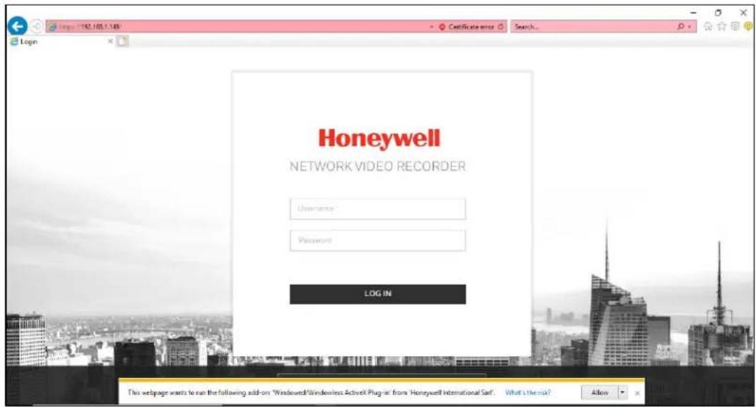
- Click Install in the ActiveX plug-ins window at the bottom of the screen and the following window is displayed:
Figure 7-2 Plugin Install
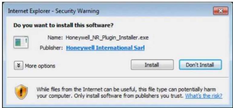
- Click Install and wait till the login window shows again. For the first login, the default username is "admin" and the password is "1234".
- Enter the username and the password and click LOG IN to enter the live view screen.
Live View Screen
Figure 7-3 Live View Screen
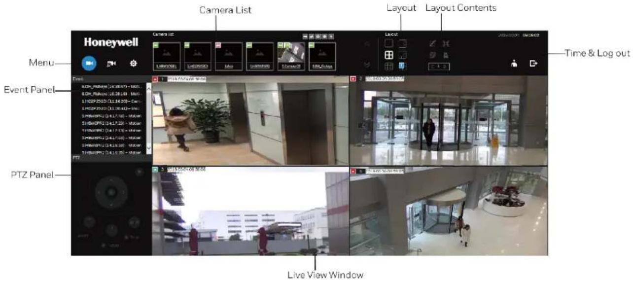
Once you log in, the system defaults to the Liveview screen, which provides access to other configuration entry. The screen elements are described as follows:
Table 7-1 Web Live View Screen
| Name Description | |
| Camera List | Provides a glimpse of all cameras inserted into your configuration. Basic information is also provided along with a screenshot. |
| Layout | Provides access to various layouts. |
| Layout contents | Provides functions to extend, rotate, and redo the layout. System Alarm In /Alarm Out are also shown in here. |
| Time & Log out | Shows the time and logout function. |
| Live View Window | Displays video streams from one or multiple cameras. Snapshot, streaming, bookmark, and audio control functions are also available on individual view cells. |
| PTZ Panel | Exerts Pan/Tilt control on a selected view cell if the camera comes with mechanical PTZ mechanism. |
| Event panel | Reports events transmitted via cameras' Alarm In connections or those by the Motion Detection, Tampering, etc. |
Camera List
The camera list displays the recruited cameras by the sequential numbering order you configured in the System Settings utility.
To arrange a view window layout, click and drag a camera from the camera list to a view window.
Figure 7-4 Camera List
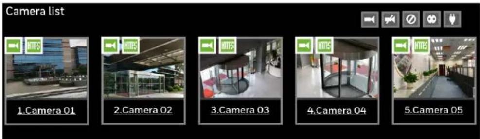
Depending on the size and screen resolution of your monitor, the snapshots of 6 cameras are displayed in this panel. If a user logged in using a credential of a limited access, he may only see cameras that he can access instead of all the cameras.
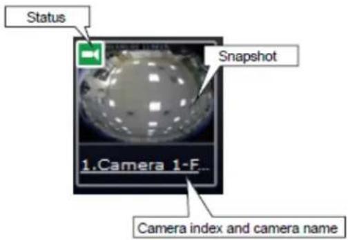
- Snapshot: the camera's image snapshot is replenished every 5 minutes. If a camera is disconnected, the last image taken will be used to represent a camera.
- Camera index & Camera name: Placing the mouse cursor on top of a camera text displays the camera index number and the camera name. Click on the camera index to display the information box.
- Status:

Online: the online status can be accompanied by the Alarm In/Alarm Out icon

Offline: camera is disconnected.

An unconfigured camera instance.

Alarm input is triggered.

Connected and recording video to system storage.

Connected with live streaming.
Disconnected or trying to establish a connection.
Layout

Figure 7-5 Layout
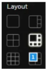
Each functional button on the screen is activated by a mouse hover. For example, the below states designate user's operation on a button:
• : not selected.
• : moused over and is ready for selection.
• : selected and is taking effects.
There are another 4 user layouts that can be individually configured. An administrator can insert camera views into these layouts and save the configuration. These user layouts can be seen by all users.
If you click the Rotate button before the configuration changes can be saved, your configuration changes will be lost.
Layout Contents
A few functional buttons are available on the Layout contents page.
Table 7-2 Layout Contents
| Clears all view cells on the current layout. | |
| Full view: extends the view cells on the current layout to the full of the screen. | |
| Exit full view. It is showed at the left side of the full view window. | |
| Rotate: the rotate function lets system display successive layout pages by the intervals of 10 seconds. The layout page that does not contain camera views will be skipped. |

Click to display the NVR's Alarm In/Alarm Out statuses.
Time & Log out
The system date and time refers to the date and time kept on the NVR system's real time clock.
Due to the limited space for the user name, user name may be partially displayed until you hover your mouse cursor.
To Log out, click

Live View Window
Figure 7-6 Live View Window
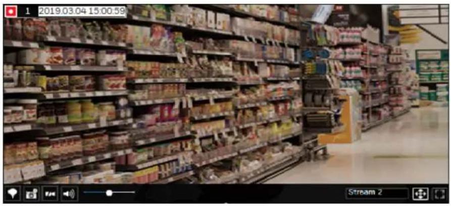
Information Bar
Figure 7-7 Information Bar

Table 7-3 Information Bar
| Connected with live streaming; a single click on this icon can trigger a manual recording. | |
| Connected and recording video to system storage. | |
| Disconnected or trying to establish a connection. | |
| 15:00:59 Video time | |
| 2019.03.04 Date | |
Tool Bar
Figure 7-8 Tool Bar

Table 7-4 Tool Bar
| Add a Bookmark (that saves a short description and a one-minute footage from the current feed). | |
| Take a snapshot. | |
| Remove camera from the view cell. | |
| Mute (if there is audio input from the camera.) | |
| Unmute | |
| Stream 2 | Stream selector. |
| Fit screen with ratio. | |
| Maximize the size of current view cell. | |
| Restore the size of current view cell. | |
| Disable digital zoom. | |
| Enable digital zoom. | |
| Volume controller. |
PTZ Panel
Figure 7-9 PTZ Panel
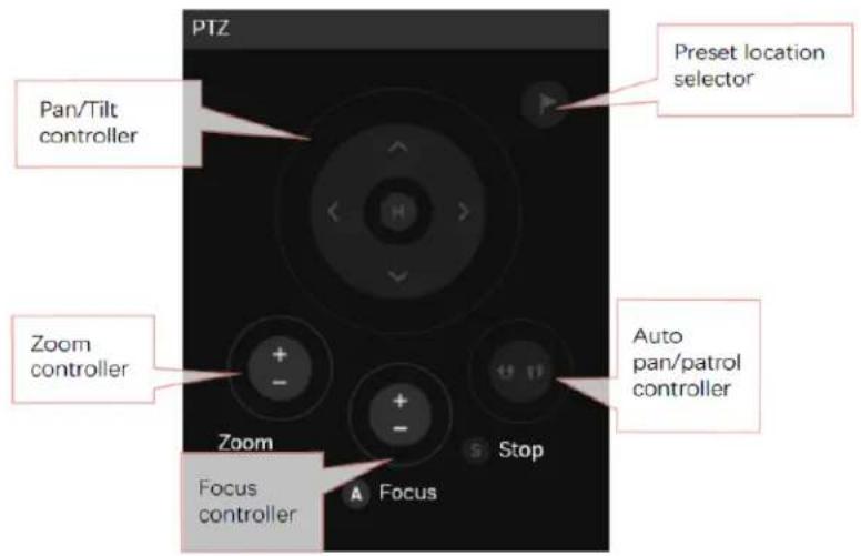
The PTZ panel takes effect for cameras that come with mechanical PTZ functions. It does not support digital PTZ functions. To utilize its functions, select a view cell populated by a PTZ camera, such as a speed dome.
Depending on the individual functions that come with PTZ cameras, some functions will not be available for every camera. For example, the zoom controller will not apply for a PTZ camera that comes without a mechanized zoom module
Event Panel
The event panel keeps up to 200 events and displays the latest 10 event entries with the latest alarm on top of the list. Older events will be erased if the number exceeds 200.
It is polled every 10 seconds. A mouse hover on an alarm entry displays full information of the event.
Note that multiple alarms can be triggered by one incident. See Setting-Event-Event on page 41 for how to configure the event settings.
If an event is configured with a recording action, there will be a play button ▶ to the left of the alarm message.
Figure 7-10 Event Panel 2
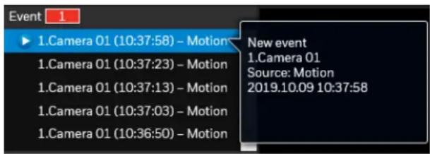
Click ▶ and the event playback window will begin playback of a footage taken 10 seconds before the occurrence of an alarm. The playback of an alarm-triggered recording will normally last for one minute. If, however, you configured a shorter pre- and post-alarm recording time, your alarm recording may be slightly shorter. The default for pre- and post-alarm buffer time are 5 seconds and 20 seconds.
Figure 7-11 Event Clips
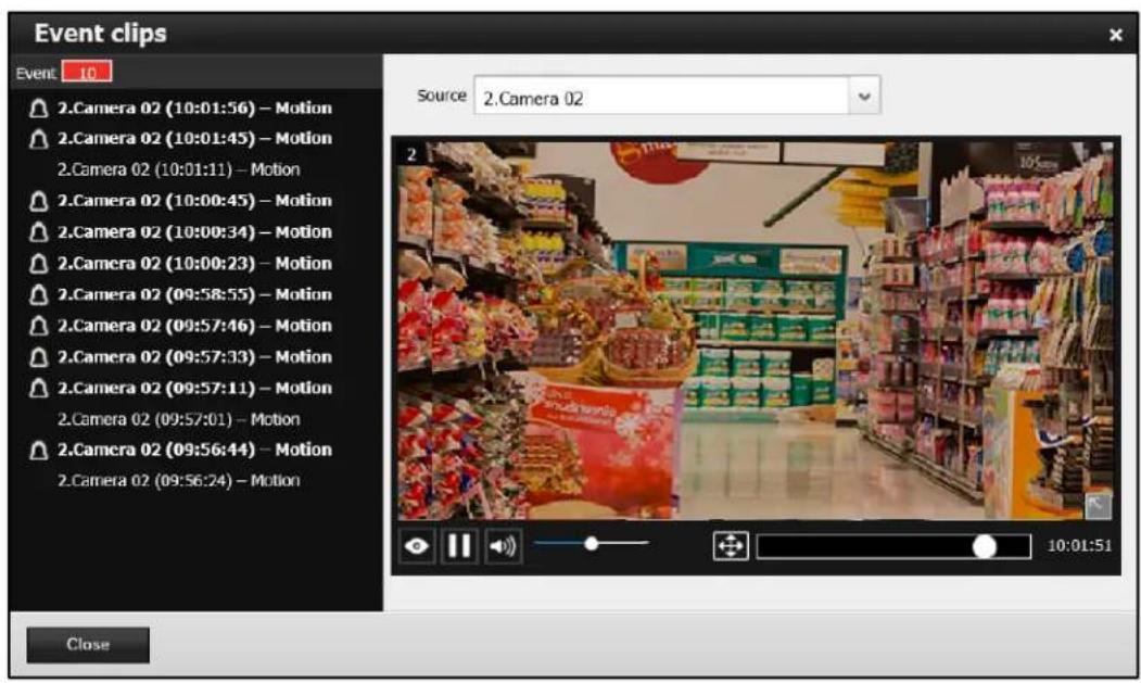
| View live video: displays the live view streaming instead of the alarm recording. | |
| Begin the event playback. | |
| Pause the current playback. | |
| Mute or unmute the audio with the current playback. Drag the controller to change the audio volume level. | |
| Fit screen with ratio. | |
| Click to enable the digital zoom function. |
Search Recording Clips Screen
Click 📋 on Figure 7-3 and the following screen is displayed:
Figure 7-12 Search Recording Clips Screen
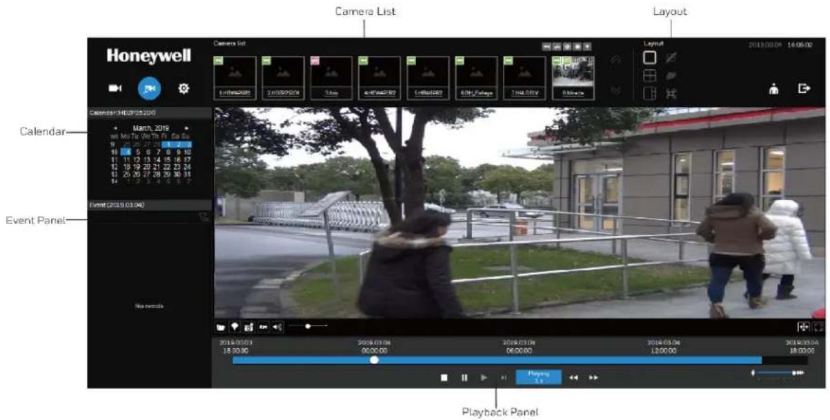
Table 7-5 Search Recording Clips Screen
| Name Description | |
| Camera List | Provides a glimpse of all cameras that have recorded data. Basic information is also provided along with a screenshot. |
| Layout | Provides functions to extend, rotate, redo the layout, and the synchronous playback. |
| Playback panel | Displays the playback functions. Snapshot, bookmark, and export functions are also available on individual view cells. |
| Event panel | Reports events transmitted via cameras' DI connections or those by the Motion Detection, etc. |
| Calendar | Shows when the recording took place, and thus enables users to quickly locate a specific part of recording in history. |
Camera List
The camera list displays the 8 added cameras by the sequential numbering order you configured in the System Settings window. The elements in the Camera list on a Search recording clips window are identical to those on a Liveview window.
To begin playback and search for past recordings:
- Double-click on a camera in the camera list. The Calendar panel will display the days video recording actually took place. And those days will be highlighted by a blue background.
Figure 7-13 Calendar
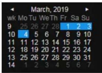
- Click the date that marked in blue.
Layout
3 types of layouts are provided for the Search recording clips window: 1x1, 2x2, and 1+3. Users can simultaneously playback up to 4 recorded videos.
Figure 7-14 Layout
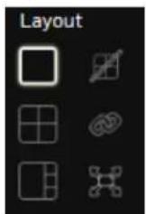
Table 7-6 Layout
| Clears layout content. | |
| Starts or stops the Synchronous playback. | |
| Full view: extends the view cells on the current layout to the full of the screen. | |
| Exit full view. It is showed at the left side of the full view window. |
Playback Panel
Figure 7-15 Playback Panel

Table 7-7 Playback Panel
II | PausePlay. This button is available after you manually pause a playback. |
 | Stop the current playback. |
 | Speed down by 1/2. The slowest speed is 1/8. |
 | Speed up. Increases the playback speed, to 2x, 4x, 8x, 16x, and then to a maximum of 32x. |
 | Display the current playback status, such as Playing, Pause, play speed, or Stop. |
 | Timeline zoomer. Use the zoomer to zoom in for more precise skimming. |
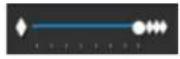 | You can use the timeline zoomer to scale down the span of time. For example, if the time span is reduced to 1 hour, then each section on the time line represents 15 minutes of recording. The total time span of a timeline starts from the minimal of 4 minutes, 20 minutes, 40 minutes, 1 hour, and up to a maximum of 24 hours. |
 | Timeline slider thumb. Click and drag this thumb button to move along and reach a specific point in time. A click on the time line will also work. |
| Note | In the Synchronous play mode, a change to the zoomer will be reflected by all synchronously playing view cells. |
Event Panel
The event panel displays the events or bookmarks recorded by the day of recording. Two additional buttons are available: Page selector and Event filter. See Creating an Event on page 41 for how to create an event.
Figure 7-16 Event Panel
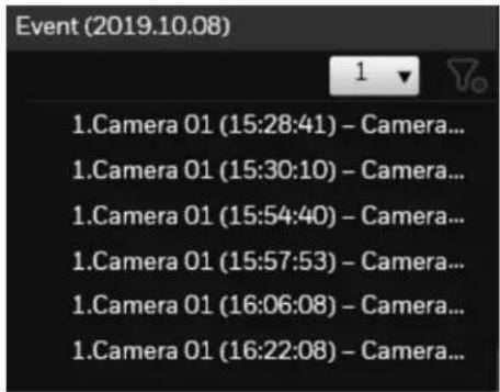
- A playback button will be available with an event-triggered recording. The event panel in the Playback window also supports the List mode and Icon mode that are similar to that in the Liveview window.
- There can be numerous alarms occurring in a day. Use the page selector to display different pages of event entries. Up to 200 entries can appear on one page. Note that the
new events that occurred seconds or minutes ago may not be instantaneously listed on the page.
Event Filter
Use the event filter to find out specific events. Use the check circles below to narrow down your search criteria by event name or event type by Motion detection, Alarm input, Alarm output, Tampering, PIR, or those manually marked down as Bookmarks.
Figure 7-17 Event Filter
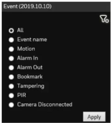
Settings Screen
The settings screen is identical to those found in the local settings. See Settings on page 27 for more information.
Honeywell Building Technologies – Security Americas (Head Office)
Honeywell Commercial Security
715 Peachtree St. NE
Atlanta, GA 30308
www.security.honeywell.com/
+1 800 323 4576
Honeywell Building Technologies - Security Mexico
Mexico: Av. Santa Fe 94, Torre A, Piso 1, Col. Zedec,
CP 0121, CDMX, Mexico.
clarsupport@honeywell.com
www.honeywell.com
01.800.083.59.25
Honeywell Colombia SAS
Honeywell Building Technologies – Security Middle East/N. Africa
Emaar Business Park, Sheikh Zayed Road
Building No. 2, 2nd floor, 201
Post Office Box 232362
Dubai, United Arab Emirates
www.honeywell.com/security/me
+971 44541704
Honeywell Building Technologies – Security Europe/South Africa
Aston Fields Road, Whitehouse Industrial Estate
Runcorn, WA7 3DL, United Kingdom
www.honeywell.com/security/uk
08448 000 235
Honeywell Building Technologies – Security Northern Europe
Stationsplein Z-W 961, 1117 CE Schiphol-Oost, The Netherlands
www.security.honeywell.com/nl
+31(0)299410200
Honeywell Building Technologies – Security
Deutschland
Honeywell Building Technologies – Security France
Immeuble Lavoisier
92160 Antony, France
www.security.honeywell.com/fr
+33(0)140962050
Honeywell Building Technologies – Security Italia SpA
Via Achille Grandi 22, 20097 San Donato Milanese (MI),
ITALY
www.security.honeywell.com/it
Honeywell Building Technologies – Security España
Josefa Valcárcel, 2428027 – Madrid, España
www.honeywell.com
+34 902 667 800
Honeywell Building Technologies – Security Россия и СНГ
121059 Moscow, Ul, Kiev 7 Russia
www.security.honeywell.com/ru
+7 (495) 797-93-71
Honeywell Building Technologies – Security Asia Pacific
Building #1, 555 Huanke Road, Zhang Jiang Hi-Tech Park
Pudong New Area, Shanghai, 201203, China
www.asia.security.honeywell.com
400 840 2233
Honeywell Building Technologies – Security and Fire (ASEAN)
Honeywell International Sdn Bhd
Level 25, UOA Corp Tower, Lobby B, Avenue 10, The Vertical,
Bangsar South City, 59200, Kuala Lumpur, Malaysia
Visit Partner Connect: www.partnerconnect.honeywell.com
Email: buildings.asean@honeywell.com
Technical support (Small & Medium
Business):
Vietnam:+84 4 4458 3369
Thailand: +66 2 0182439
Indonesia: +62 21 2188 9000
Malaysia: +60 3 7624 1530
Singapore: +65 3158 6830
Philippines: +63 2 231 3380
Honeywell Home and Building Technologies (India)
HBT India Buildings
Unitech Trade Centre, 5th Floor,
Sector - 43, Block C, Sushant Lok Phase - 1,
Gurgaon - 122002, Haryana, India
Visit Partner Connect: www.partnerconnect.honeywell.com
Email: HBT-IndiaBuildings@honeywell.com
Toll Free No: 1-800-103-0339
+91 124 4975000
Honeywell Building Technologies – Security and Fire (Korea)
Honeywell Co., Ltd. (Korea)
5F SangAm IT Tower,
434, Worldcup Buk-ro, Mapo-gu,
Seoul 03922, Korea
Visit: http://www.honeywell.com
Email: info.security@honeywell.com
Customer support: HSG-CS-KR@honeywell.com; +82 1522-8779
+82-2-799-6114
Honeywell Building Technologies – Security & Fire (Pacific)
Honeywell Ltd
9 Columbia Way
BAULKHAM HILLS NSW 2153
Visit: www.honeywellsecurity.com.au
Email: hsf.comms.pacific@Honeywell.com
Technical support:
Australia: 1300 220 345
New Zealand: +64 9 623 5050
Honeywell
www.honeywell.com/security
+1 800 323 4576 (North America only)
https://www.honeywellsystems.com/ss/techsupp/index.html
Document 800-25988 - Rev C - 05/2020
© 2019 Honeywell International Inc. All rights reserved. No part of this publication may be reproduced by any means without written permission from Honeywell. The information in this publication is believed to be accurate in all respects. However, Honeywell cannot assume responsibility for any consequences resulting from the use thereof. The information contained herein is subject to change without notice. Revisions or new editions to this publication may be issued to incorporate such changes. For patent information, see www.honeywell.com/patents.