
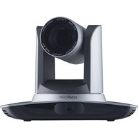
BG-UPTZ-12XHSU - Security Camera BZBGear - Free user manual and instructions
Find the device manual for free BG-UPTZ-12XHSU BZBGear in PDF.


| Product Type | PTZ Security Camera |
| Model | BG-UPTZ-12XHSU |
| Brand | BZBGear |
| Sensor | 1/2.8-inch CMOS, 2.07 Megapixels |
| Video Resolution | Up to 1920x1080 @ 60 fps |
| Optical Zoom | 12X (f=3.9-46.8mm) |
| Digital Zoom | 10X |
| View Angle | 55.8° (Wide) - 3.2° (Tele) |
| Pan Range | ±170° |
| Tilt Range | -30° to +90° |
| Preset Positions | 255 (10 via remote) |
| Video Output Interfaces | HDMI, 3G-SDI, USB3.0, LAN |
| Control Interfaces | RS232 (in/out), RS422/RS485 |
| Control Protocols | VISCA, Pelco-D, Pelco-P |
| Network Protocols | ONVIF, GB/T28181, RTSP, RTMP, RTP multicast |
| Audio Compression | AAC, MP3, G.711A |
| Video Compression | H.264, H.265 |
| Dimensions | 178 x 115.5 x 150.9 mm |
| Weight | 1.38 kg |
| Power Supply | DC 12V ±10%, Max 1A (12W) |
| Warranty | 3-Year Stress-Free Warranty |
| Maintenance & Cleaning | Clean lens with soft dry cloth; use mild detergent if needed; avoid corrosive cleaners |
| Safety | Do not expose to rain/moisture; installation by qualified technician; do not open case |
Frequently Asked Questions - BG-UPTZ-12XHSU BZBGear
User questions about BG-UPTZ-12XHSU BZBGear
0 question about this device. Answer the ones you know or ask your own.
Ask a new question about this device
Download the instructions for your Security Camera in PDF format for free! Find your manual BG-UPTZ-12XHSU - BZBGear and take your electronic device back in hand. On this page are published all the documents necessary for the use of your device. BG-UPTZ-12XHSU by BZBGear.
USER MANUAL BG-UPTZ-12XHSU BZBGear
Attention
Improper operations may damage the product structure and result in mechanical failure. Please note the following tips:

Do not move the camera by grabbing the head.
Move the camera by holding the bottom with one or both hands.
Please do not rotate the lens and holder manually regardless of camera being powered on or off; any damage to the camera structure will result in failure of the camera's self-check and self-start operations.

This manual introduces functionality, proper installation and operations for this PTZ camera in details. Please read this manual carefully before installation and use.
1. Cautions
1.1 Avoid product damage caused by heavy pressure, strong vibration or immersion during transportation, storage and installation.
1.2 Housing of this product is made of organic materials. Do not expose it to any liquid, gas or solids which may corrode the shell.
1.3 Do not expose the product to rain or moisture.
1.4 To prevent the risk of electric shock, do not open the case. Installation and maintenance should only be carried out by qualified technicians.
1.5 Do not use the product beyond the specified temperature, humidity, or power supply specifications.
1.6 Wipe it with a soft, dry cloth when cleaning the camera lens. Wipe it gently with a mild detergent if needed. Do not use strong or corrosive detergents to avoid scratching the lens and affecting the image.
1.7 This product contains no parts which can be maintained by users themselves. Any damage caused by dismantling the product by user without permission is not covered by warranty.
2. Electrical Safety
Installation and use of this product must strictly comply with local electrical safety standards.
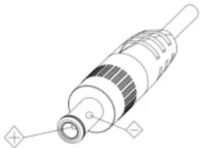
The power supply of the product is ±12V, the max electrical current is 2A.
3. Install
1.1 Do not rotate the camera head aggressively, otherwise it may cause mechanical failure.
1.2 This product should be placed on a stable desktop or on a horizontal surface. Do not install the product obliquely, otherwise it may display an inclined image.
1.3 Ensure there are no obstacles within the rotation circumference of the holder.
1.4 Do not power on until cabling installation is complete for proper operation and synchronizing.
4. Magnetic Interference
Electromagnetic fields at specific frequencies may affect the video image. This product is Class A. It may cause radio interference in household application. Appropriate measure is required.
Content
1. Camera Installation 2
1.1 Camera Introduction....2
1.2 Interfaces and Connection .... 3
1.3 Mounting Brackets....3
2. Product Overview 7
2.1 Dimensions 7
2.2 Accessories....8
2.3 RS-232 Interface 8
2.5 Rotary DIP Switch....9
2.6 Main Features.... 10
2.6 Specifications....10
3. Remote Control....12
3.1 Match Code for Wireless Remote Control.... 12
3.2 Keys Introduction for IR Remote Control 13
3.3 Menu Introduction....15
4. Network Configuration 17
- Network Connection.... 17
4.1 Connection Mode 17
4.2 Web Browser Login....18
4.2.1 Web client.... 18
4.3 Streaming....19
5. Serial port communication and control 20
5.1 VISCA Protocol Return Command 20
5.2 VISCA Protocol Control Command 21
5.3 VISCA Protocol Inquiry Command 24
5.4 Pelco-D protocol command list.... 26
5.5 Pelco-P protocol command list 26
6. Maintenance and Troubleshooting.... 27
6.1 Maintenance....27
6.2 Troubleshooting....27
7. Warranty 28
8. Mission Statement.... 28
9. Copyright 28
1. Camera Installation
1.1 Camera Introduction
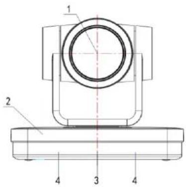


Figure 1.1
- Camera Lens
- Camera Base
- Remote Control Receiving Indicator
- Infrared Receiver
- Tripod Screw Hole
- Screw Hole for Tripod
- HDM Output
- USB3.0 Output
-
SDI Output
-
Audio Input Interface (Line-in)
- Rotary DIP Switch
- RS232 Control Interface (input)
- RS232 Control Interface (output)
- RS422 Interface (Compatible with RS485)
- Network Interface (LAN)
- DC12V Input Power Supply Socket
- Power Switch
1.2 Interfaces and Connection

Figure 1.3 Wiring Diagram
1) After powering on and self-starting, the camera will automatically return to the preset (0) position once it's pre-set.
2) The default address for the IR remote control is 1#.
If restored to factory defaults, note that the remote control default address will be restored to 1#.
1.3 Mounting Brackets
Notes:
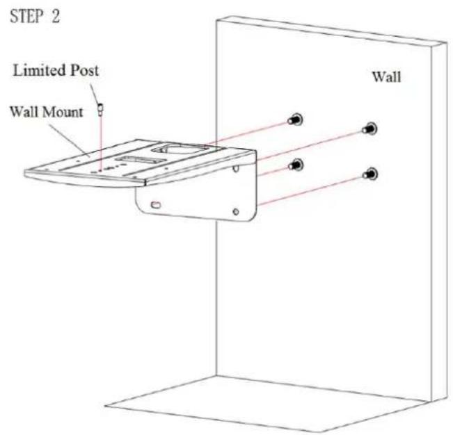
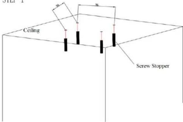
Ceiling or wall mounting brackets should only be installed on sturdy walls rated to support mounted objects.
For safety reason, plasterboard is not recommended.
1) Wall Mounting:




2) Ceiling Mounting

STEP 1
STEP 2


2. Product Overview
2.1 Dimensions


Figure 2.2 Product Dimension
2.2 Accessories
| Standard Accessories | Optional Accessories |
| Power adapter | Ceiling Mount |
| IR Remote Control | Wall Mount |
| RS232 Cable | |
| User Manual | |
| USB3.0 Cable |
2.3 RS-232 Interface
1) RS-232 Interface Definition

Connection to PC or Camera Controller
![graph TD A["Camera"] --> B["1.DTR"] A --> C["2.DSR"] A --> D["3.TXD"] A --> E["4.GND"] A --> F["5.RXD"] A --> G["6.GND"] A --> H["7.IR OUT"] A --> I["8.NC"] J["WindowsDB-9"] --> K["1.DCD"] J --> L["2.RXD"] J --> M["3.TXD"] J --> N["4.DTR"] J --> O["5.GND"] J --> P["6.DSR"] Q["WindowsDB-9"] --> R["7.…](/content/2026/05/1059324/images/2c3f5a35dbce4efd10bde056b222e2e62d2f8e38255b9ab5d32dc3b2d59eae56.jpg)

2) RS232 Mini-DIN 8-pin: Port Definition

| NO. | Port | Definition |
| 1 | DTR | Data Terminal Ready |
| 2 | DSR | Data Set Ready |
| 3 | TXD | Transmit Data |
| 4 | GND | Signal Ground |
| 5 | RXD | Receive Data |
| 6 | GND | Signal Ground |
| 7 | IR OUT | IR Commander Signal |
| 8 | NC | No Connection |
3) RS232 (DB9) Port Definition
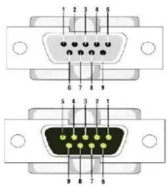
| NO. | Port | Definition |
| 1 | DCD | Data Carrier Detect |
| 2 | RXD | Receive Data |
| 3 | TXD | Transmit Data |
| 4 | DTR | Data Terminal Ready |
| 5 | GND | System Ground |
| 6 | DSR | Data Set Ready |
| 7 | RTS | Request to Send |
| 8 | CTS | Clear to Send |
| 9 | RI | Ring Indicator |
4) VISCA networking as shown below:
![graph TD A["VISCA Controller"] --> B["VISCA Equipment"] B --> C["IN OUT"] B --> D["IN OUT"] B --> E["IN OUT"] C --> F["Computer"] D --> F E --> F](/content/2026/05/1059324/images/2199c240554ca03ee534bda08f02540ee636a4e21cb05a4a4058a5ffab028441.jpg)
![graph TD A["1.DTR"] --> B["2.DSR"] C["3.TXD"] --> D["4.GND"] E["5.RXD"] --> F["6.GND"] G["7.IR OUT"] --> H["8.NC"] I["1.DTR"] --> J["2.DSR"] K["3.TXD"] --> L["4.GND"] M["5.RXD"] --> N["6.GND"] O["7.OPEN"] --> P["8.OPEN"]](/content/2026/05/1059324/images/bd45c2c38b91155a328f98d42ca2a7e36a1cf20cefc6d9bcab2a35d9be19445a.jpg)
2.5 Rotary DIP Switch
| Dial-up | video format | Dial-up | video format |
| 0 | 1080P60 | 8 | 720P30 |
| 1 | 1080P50 | 9 | 720P25 |
| 2 | 1080I60 | A | 1080P59.94 |
| 3 | 1080I50 | B | 1080I59.94 |
| 4 | 720P60 | C | 720P59.94 |
| 5 | 720P50 | D | 1080P29.97 |
| 6 | 1080P30 | E | 720P29.97 |
| 7 | 1080P25 | F | video format to be set on the menu |

Note: 1. Please remember to reboot the camera to take effect when video format is switched.
- If switch to F, please power off and reboot to take effect.
2.6 Main Features
This model series is packed with functions, superior performance, and rich video output interfaces. Featuring advanced ISP processing algorithms, offering vivid and high-resolution video with a strong sense of depth and fantastic color rendition. It supports H.264/H.265 encoding which makes motion video more fluent and clearer under low bandwidth conditions.
● Full HD Resolution: 1/2.8-inch-high quality CMOS sensor. Resolution is up to 1920x1080 with frame rate up to 60 fps.
● Multiple Optical Zoom Lens: 10X/12X/20X/30X optical zoom lens.
● Leading Auto Focus Technology: Fast, accurate and stable auto focusing technology.
- Low Noise and High SNR: Super high SNR image is achieved with low noise CMOS. Advanced 2D/3D noise reduction technology further reduces the noise while ensuring high image clarity.
- Multiple video output interfaces: HDMI, 3G-SDI, CVBS, LAN. Simultaneously output audio and video signal via HDMI, SDI and LAN. SDI output capable of sending signals up to 100M supportive of 1080P@60fps
- Multiple Audio/Video Compression Standards: Support H.264/H.265 video compression, up to 1920×1080 resolution 60 fps; support AAC, MP3 and G.711A audio compression, 8000,16000,32000,44100,48000 sampling frequency
● Built-in Gravity Sensor: supports PTZ auto-flip functionality and simple installation.
- Multiple Network Protocols: ONVIF, GB/T28181, RTSP, RTMP / RTMP(s) protocols; Supports RTMP push mode, connectable to streaming servers (Wowza / FMS); Supports RTP multicast mode; Supports full command VISCA / VISCA IP control protocol.
● Control Interface: RS485, RS232 (cascade connection)
- Multiple Control Protocol: Support VISCA, PELCO-D, PELCO-P protocols; Supports automatic identification protocols.
- Quiet Pan / Tilt Movement: Designed with high accuracy step driving motor, camera pans and tilts quietly and smoothly.
● Auto sleep function: Auto sleep/wake up function with low power consumption, less than 400mw.
● Multiple presets: Up to 255 presets (10 presets via remote control).
- IR / Wireless Remote Control: Users can choose IR remote control or wireless remote control according to different conditions. (Sold Separately) The 2.4G wireless remote control is unaffected by angles, distance or infrared interference. Far-end-control is also available.
- Multiple Application: Online-education, Lecture Capture, Webcasting, Video conferencing, Tele-medicine, Unified Communication, Emergency command and control systems, etc.
2.6 Specifications
| Model | 5X | 10X | 12X | 20X | 30X |
| Camera Parameter | |||||
| Optical Zoom | 5Xf=3.1-15.5mm | 10Xf=4.7-47mm | 12Xf=3.9-46.8mm | 20X5.2-98mm | 30Xf=4.3-129mm |
| Sensor | 1/2.8-inch high quality HD CMOS sensor | ||||
| Effective Pixels | 16: 9, 2.07 megapixel | ||||
| Video Format | HDMI/SDI video format1080P60/50/30/25/59.94/29.97, 1080I60/50/59.94, 720P60/50/30/25/59.94/29.97CVBS output: 570i 480i | ||||
| USB3.0 interface video format:Main-Stream: YUY2/MJPEG/NV12/H.264/H.265:1920×1080P30,1280×720P30,1024×576P30,960×540P30,800×448P30,720×480P30,640×360P30,640×480P30,320×176P30Sub-Stream: YUY2/NV12: 640×360P30,640×480P30,320×176P30MJPEG/H.264/H.265: 1920×1080P30,1280×720P30,1024×576P30,960×540P30,800×448P30,720×480P30,640×360P30,640×480P30,320×176p30 | |||||
| View Angle | 60.9°(W)6.43°(T) | 72.5°(W)6.3°(T) | 55.8° (W)3.2°(T) | 65.1°(W)2.34°(T) | |
| AV | F1.6 - F3.0 | F1.8 - F2.4 | F1.5~ F3.0 | F1.6 - F4.7 | |
| Digital Zoom | 10X | ||||
| Minimum Illumination | 0.5Lux (F1.8, AGC ON) | ||||
| DNR | 2D & 3D DNR | ||||
| White Balance | Auto / Manual/ One Push/ Specify color temperature (range: 2400k-7100k) | ||||
| Focus/Aperture/Electronic Shutter | Auto/Manual/One Push Focus | ||||
| Iris | Auto/Manual | ||||
| Shutter | Auto/Manual | ||||
| BLC | ON/OFF | ||||
| WDR | OFF/ Dynamic level adjustment | ||||
| Video Adjustment | Brightness, Color, Saturation, Contrast, Sharpness, B/W mode, Gamma curve | ||||
| SNR | >50dB | ||||
| Input/output Interface | |||||
| Video Interfaces | HDMI, SDI, LAN, USB3.0, RS232-IN/OUT, RS422 (compatible with RS485), A-IN, rotary DIP switch, DC 12V port, power switch | ||||
| Video Output | HDMI, SDI, LAN, USB3.0 | ||||
| Video Stream | Dual stream output | ||||
| Video Compression Format | LAN Interface: H.265, H.264, Dual stream outputUSB3.0 Interface: YUY2, MJPEG, H.264, NV12, H.265 | ||||
| Audio Input Interface | Double track 3.5mm linear input | ||||
| Audio Output Interface | HDMI, SDI, LAN, USB3.0 | ||||
| Audio Compression Format | AAC/MP3/G.711A | ||||
| Control Interface | RS232, RS485 | ||||
| Control Protocol | VISCA / Pelco-D / Pelco-P, Baud Rates: 115200/9600/4800/2400bps | ||||
| Power Interface | HEC3800 outlet (DC12V) | ||||
| Input Voltage | DC12V±10% | ||||
| Input Electric Current | Maximum: 1A | ||||
| Power Consumption | Maximum: 12W | ||||
| Network Protocols | TCP/IP, RTSP, RTMP, ONVIF, GB/T28181Network VISCA control protocol.Supports remote upgrade, reboot and reset | ||||
| USB Communication | UVC (Video), UAC (UAC) | ||||
| PTZ Parameter | |||||
| Pan/Tilt Rotation | ±170°, -30°~+90° | ||||
| Pan Control Speed | 0.1 - 60°/sec | ||||
| Tilt Control Speed | 0.1- 30°/sec | ||||
| Preset Speed | Pan: 60°/sec, Tilt: 30°/sec | ||||
| Preset Number | 255 presets (10 presets via remote control) | ||||
| Other Parameter | |||||
| Stored Temperature | -10°C~+60°C | ||||
| Storage Humidity | 20%~95% | ||||
| Working Temperature | -10°C~+50°C | ||||
| Working Humidity | 20%~80% | ||||
| Dimension | 178mmX115.5mmX150.9mm | ||||
| Weight | 1.38KG | ||||
| Attachment | |||||
| Package | 12V/1.5A Power supply, RS232 control cable, IR Remote Control, User Manual | ||||
| Optional Accessories | Ceiling / wall mount (additional cost) | ||||
3. Remote Control
3.1 Match Code for Wireless Remote Control
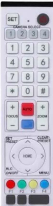
One to One Code Matching:
Press the "set" and "*" keys combined for 3 seconds, LED indicator starts flashing. Camera will receive the signal and power on. LED indicator will turn off if the code matching successfully. The camera can be controlled by the wireless remote control only after one to one code pairing. Otherwise please clear the code matching of this remote control or use the other remote control to pair with the camera again.
If one to one code matching fails, the red LED light flashes for 20 seconds and then will go off, camera will halt code matching and activate sleep mode; Press any key to wake the camera up and re-match code.
Note: Upon matching code successfully, please select the camera's address to control it.
Clear Code:
Press the "set" and "*" keys combined for 3 seconds, LED indicator starts flashing. Camera will power off and on, the LED indicator will go off if code clearing is successful.
Sleep Mode and Wake Up:
Press any key to wake up the camera from sleep mode.
3.2 Keys Introduction for IR Remote Control
1). In this manual, "press the key" means a click rather than a long-press, and a special note will be given if a long-press for more than one second is required.
2). When a key-combination is required, do it in sequence. For example, 【*】+【#】+【F1】 means press “【*】” first and then press “【#】” and last press “【F1】”.
1. Standby Key
The camera enters standby mode if pressing for (3's) on the standby key.
Press and hold for (3's) again on the standby key, the camera will self-check again and return to the HOME position (If preset (0) position is set, the camera will return to the preset (0) position).
2. Camera Selection
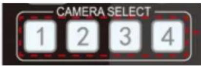
Select the camera's address to control it.
3. Focus Control
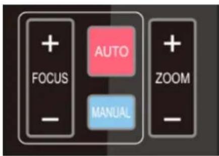
Auto: Auto focus mode
Manual: Manual focus mode
Focus + (near): Press 【FOCUS +】 key (Valid only in manual focus mode)
Focus - (far): Press 【FOCUS -】 key (Valid only in manual focus mode)
Press and hold the keys, focusing will continue and stop based on the key being pressed and released.
4. Zoom Control

ZOOM +: press【ZOOM +】key to zoom in
Press and hold the keys, the action of focus will keep continue and stop as soon as the key is released.
5. Set and Clear Presets

6. Pan/Tilt Control
7. Menu Setting
8. Camera Remote Control Address Setting

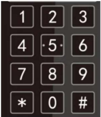
Set Preset: press 【SET PRESET】 button, and then press the number key 0-9 to set preset positions.
Note: 10 presets via remote control.
Call Preset: Press a number key 0-9 directly to call a preset position.
Clear Preset: press 【CLEAR PRESET】 button, and then press the number key 0-9 to clear preset positions.
Note: press the【#】key three times continually to clear all presets.
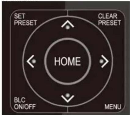
Up: press ▲ Down: press ▲ Left: press ▼ Right: press ▲
Back to middle position: press 【HOME】
Press and hold the up/down/left/right key, the pan/tilt movements will keep running, from slow to fast, until it runs to the endpoint; stop as soon as the key is released.
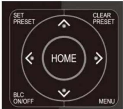
【MENU】: Open / close the OSD menu
【HOME】: Camera lens back to the middle position; Confirm button; Enter next menu
【BLC ON/OFF】: Turn on or off the back light compensation
【*】+【#】+【F1】:Camera Address No.1
【*】+【#】+【F2】:Camera Address No. 2
【*】+【#】+【F3】:Camera Address No. 3
Note: If the address of former remote control is not address (1) but another one from 2, 3, 4, the corresponding camera address will restore to address 1 when all parameters are restored to factory default. User should change the remote control address to address 1.
3.3 Menu Introduction
Note: Menu must be exited for settings to apply
1). Menu Control
【MENU】: Enter / exit the OSD menu or return to the previous menu
【HOME】: Enter next menu
4. Network Connection
4.1 Connection Mode
Direct connection: Connect the camera directly to the computer by using an ethernet cable.
Internet connection mode: Connect the camera and computer to a router or switch and access via the local area network (LAN).
Note: Ensure power and network connections are secured to prevent video issues caused by poor connection quality.
The computer must be on the same subnet as the camera to connect successfully. The device will not be accessible otherwise. The camera default IP address is 192.168.5.163, therefore the computer must be connected to the 192.168.5.x subnet.
To connect to the camera open the Local Area Connection Properties on the computer.
For Windows users right-click on the internet connection in the lower right corner of the desktop.
Select "Open Network & Internet Settings".
Select "Change Adapter Options".
Right-click on your connection (Wi-Fi or Ethernet) and select "Properties".
Select "Internet protocol version 4 (TCP/IPv4)" as shown below and click "Properties".

For the following steps refer to the diagram below.
Click on the bubble for "Use the following IP address"
In the IP address field enter a non-conflicting IP address on the same subnet as the camera. If there is another device with the same IP address you will not be able to connect. In the example below we are using 192.168.5.200
In the Subnet mask field enter 255.255.255.0
In the Default gateway field type 192.168.5.1
You can leave the DNS fields blank.
Click OK to apply your settings.
NOTE: When you are finished configuring the camera you will need to return to this screen and click the bubbles for "Obtain an IP address automatically" and "Obtain DNS server automatically" to restore internet connectivity to your computer. Also make sure to reconnect any ethernet cables you may have unplugged.

4.2 Web Browser Login
4.2.1 Web client
1) Web client Log In
Enter 192.168.5.163 in the address bar of your internet browser and click Enter. If logged in as administrator (Default Username/Password: admin), users can preview and configure in the Web Client. If logged in as a normal user (Default Username/Password:user1 or user2), users can only preview with no options for configuration.
4.3 Streaming
1). Video Stream Capture
Configurations -> Video Configure-> Video Encode

Configure the parameters according to the network environment.
Note: stream name live/av0 (live/ XXX)
For example:
The default IP address of the camera is 192.168.5.163. The way to obtain the RTSP video stream is as below rtsp://192.168.5.163:554/live/av0 (av0 main stream)
rtsp://192.168.5.163:554/live/av1 (av1 sub stream)
The default IP address of the camera is 192.168.5.163. the way to obtain RTMP video stream is as below rtmp://192.168.5.163:1935/live/av0 (av0 main stream)
rtmp://192.168.5.163:1935/live/av1 (av1 sub stream)
2). Push Video Stream
Configurations -> Video Configure-> Stream Publish

Push RTMP stream to public network server, the stream camera must be on the public network, otherwise it will fail to connect to server.
Host address: server address, which can be either a domain name or an IP address
Host port: server default port number
Stream name: live/test (live/ XXX)
Username and password: the username and password set by the server, or leave it empty
Access URL: rtmp://host domain name: host port/live/xxx
Or (rtmp://host IP address: host port/live/xxx)
5. Serial port communication and control
The camera could be controlled through RS232/RS485 interface; RS232C serial parameter are as follows: Baud rate: 2400/4800/9600/115200 bits / sec; Start bit: 1; data bits: 8; Stop bit: 1; Parity: None.
5.1 VISCA Protocol Return Command
| Ack/Completion Message | ||
| Command packet | Note | |
| ACK | z0 41 FF | Returned when the command is accepted. |
| Completion | z0 51 FF | Returned when the command has been executed. |
z = camera address + 8
| Error Messages | ||
| Command packet | Note | |
| Syntax Error | z0 60 02 FF | Returned when the command format is different or when a command with illegal command parameters is accepted |
| Command Not Executable | z0 61 41 FF | Returned when a command cannot be executed due to current conditions. For example, when commands controlling the focus manually are received during auto focus. |
5.2 VISCA Protocol Control Command
| Command | Function | Command packet | Note |
| AddressSet | Broadcast | 88 30 0p FF | p: Address setting |
| IF_Clear | Broadcast | 88 01 00 01 FF | I/F Clear |
| CommandCancel | 8x 21 FF | ||
| CAM_Power | On | 8x 01 04 00 02 FF | Power ON/OFF |
| Off | 8x 01 04 00 03 FF | ||
| CAM_Zoom | Stop | 8x 01 04 07 00 FF | |
| Tele(Standard) | 8x 01 04 07 02 FF | ||
| Wide(Standard) | 8x 01 04 07 03 FF | ||
| Tele(Variable) | 8x 01 04 07 2p FF | p = 0(low) - F(high) | |
| Wide(Variable) | 8x 01 04 07 3p FF | ||
| Direct | 8x 01 04 47 0p 0q 0r 0s FF | pqrs: Zoom Position | |
| CAM_Focus | Stop | 8x 01 04 08 00 FF | |
| Far(Standard) | 8x 01 04 08 02 FF | ||
| Near(Standard) | 8x 01 04 08 03 FF | ||
| Far(Variable) | 8x 01 04 08 2p FF | p = 0(low) - F(high) | |
| Near (Variable) | 8x 01 04 08 3p FF | ||
| Direct | 8x 01 04 48 0p 0q 0r 0s FF | pqrs: Focus Position | |
| Auto Focus | 8x 01 04 38 02 FF | ||
| Manual Focus | 8x 01 04 38 03 FF | ||
| One Push mode | 8x 01 04 38 04 FF | ||
| CAM_Zoom Focus | Direct | 8x 01 04 47 0p 0q 0r 0s0t 0u 0v 0w FF | pqrs: Zoom Positiontuvw: Focus Position |
| CAM_AFSensitivity | High | 8x 01 04 58 01 FF | Focus sensitivity Setting |
| Normal | 8x 01 04 58 02 FF | ||
| Low | 8x 01 04 58 03 FF | ||
| CAM_AFZone | Top | 8x 01 04 AA 00 FF | Focus Region Setting |
| Center | 8x 01 04 AA 01 FF | ||
| Bottom | 8x 01 04 AA 02 FF | ||
| ALL | 8x1 01 04 AA 03 FF | ||
| CAM_WB | One Push mode | 8x 01 04 35 03 FF | |
| One Push Trigger | 8x 01 04 10 05 FF | One Push WB Trigger (Enabled during OnePush WB mode) | |
| CAM_WB Mode | 8x 01 04 35 pq FF | pq = 00--33 WBMode | |
| CAM_AWBSensitivity | Low | 8x 01 04 A9 00 FF | WB Sensitivity Setting |
| Normal | 8x 01 04 A9 01 FF | ||
| High | 8x 01 04 A9 02 FF | ||
| CAM_RGain | Reset | 8x 01 04 03 00 FF | Manual Control of R Gain |
| Up | 8x 01 04 03 02 FF | ||
| Down | 8x 01 04 03 03 FF | ||
| Direct | 8x 01 04 43 00 00 0p 0q FF | pq: R Gain | |
| CAM_Bgain | ResetUp | 8x 01 04 04 00 FF8x 01 04 04 02 FF | Manual Control of B Gain |
| Down | 8x 01 04 04 03 FF | ||
| Direct | 8x 01 04 44 00 00 0p 0q FF | pq: B Gain | |
| CAM_AE | Full Auto | 8x 01 04 39 00 FF | Automatic Exposure mode |
| Manual | 8x 01 04 39 03 FF | Manual Control mode | |
| Shutter priority | 8x 01 04 39 0A FF | Shutter Priority Automatic Exposure mode | |
| Iris priority | 8x 01 04 39 0B FF | Iris Priority Automatic Exposure mode | |
| Bright | 8x 01 04 39 0D FF | Bright mode | |
| CAM_Shutter | Reset | 8x 01 04 0A 00 FF | Shutter Setting |
| Up | 8x 01 04 0A 02 FF | ||
| Down | 8x 01 04 0A 03 FF | ||
| Direct | 8x 01 04 4A 00 00 0p 0q FF | pq: Shutter Position | |
| CAM_Iris | Reset | 8x 01 04 0B 00 FF | Iris Setting |
| Up | 8x 01 04 0B 02 FF | ||
| Down | 8x 01 04 0B 03 FF | ||
| Direct | 8x 01 04 4B 00 00 0p 0q FF | pq: Iris Position | |
| CAM_Gain Limit | Reset | 8x 01 04 0C 00 FF | Gain Limit Setting |
| Up | 8x 01 04 0C 02 FF | ||
| Down | 8x 01 04 0C 03 FF | ||
| Gain Limit | 8x 01 04 2C 0p FF | p: Gain Position | |
| CAM_Bright | Reset | 8x 01 04 0D 00 FF | Bright Setting |
| Up | 8x 01 04 0D 02 FF | ||
| Down | 8x 01 04 0D 03 FF | ||
| Direct | 8x 01 04 4D 00 00 0p 0q FF | pq: Bright Position | |
| CAM_ExpComp | On | 8x 01 04 3E 02 FF | Exposure Compensation ON/OFF |
| Off | 8x 01 04 3E 03 FF | ||
| Reset | 8x 01 04 0E 00 FF | Exposure Compensation Amount Setting | |
| Up | 8x 01 04 0E 02 FF | ||
| Down | 8x 01 04 0E 03 FF | ||
| Direct | 8x 01 04 4E 00 00 0p 0q FF | pq: ExpComp Position | |
| CAM_Back Light | On | 8x 01 04 33 02 FF | Back Light Compensation |
| Off | 8x 01 04 33 03 FF | ||
| CAM_WDRStrength | Reset | 8x 01 04 21 00 FF | WDR Level Setting |
| Up | 8x 01 04 21 02 FF | ||
| Down | 8x 01 04 21 03 FF | ||
| Direct | 8x 01 04 51 00 00 00 0p FF | p: WDR Level Position | |
| CAM_NR | 2D | 8x 01 04 53 0p FF | P=0-7 0:OFF |
| 3D | 8x 01 04 54 0p FF | P=0-8 0:OFF | |
| CAM_Gamma | 8x 01 04 5B 0p FF | p = 0 - 4 0: Default 1: 0.45 2: 0.50 3: 0.55 4: 0.63 | |
| CAM_Low-Light Mode | ON | 8x 01 04 2D 01 FF | Low-Light Mode Setting |
| OFF | 8x 01 04 2D 00 FF | ||
| CAM_Flicker | OFF | 8x 01 04 23 00 FF | OFF |
| 50HZ | 8x 01 04 23 01 FF | 50HZ | |
| 60HZ | 8x 01 04 23 02 FF | 60HZ | |
| CAM_Aperture | Reset | 8x 01 04 02 00 FF | Aperture Control |
| Up | 8x 01 04 02 02 FF | ||
| Down | 8x 01 04 02 03 FF | ||
| Direct | 8x 01 04 42 00 00 0p 0q FF | pq: Aperture Gain | |
| CAM_Picture effect | B&W-Mode | 8x 01 04 63 04 FF | Picture effect Setting |
| OFF | 8x 01 04 63 00 FF | ||
| CAM_Memory | Reset | 8x 01 04 3F 00 pq FF | pq: Memory Number (=0 to 254)Corresponds to 0 to 9 on the Remote Commander |
| Set | 8x 01 04 3F 01 pq FF | ||
| Recall | 8x 01 04 3F 02 pq FF | ||
| CAM_LR_Reverse | On | 8x 01 04 61 02 FF | Image Flip Horizontal ON/OFF |
| Off | 8x 01 04 61 03 FF | ||
| CAM_PictureFlip | On | 8x 01 04 66 02 FF | Image Flip Vertical ON/OFF |
| Off | 8x 01 04 66 03 FF | ||
| CAM_ColorSaturation | Direct | 8x 01 04 49 00 00 00 0p FF | P=0-E0:60% 1:70% 2:80% 3:90% 4:100%5:110% 6:120% 7:130% 8:140%9:150% 10:160% 11:160% 12:180%13:190% 14:200% |
| CAM_IDWrite | 8x 01 04 22 0p 0q 0r 0s FF | pqrs: Camera ID (=0000 to FFFF) | |
| SYS_Menu | ON | 8x 01 04 06 06 02 FF | Turn on the menu screen |
| OFF | 8x 01 04 06 06 03 FF | Turn off the menu screen | |
| IR_Receive | ON | 8x 01 06 08 02 FF | IR(remote commander)receive On/Off |
| OFF | 8x 01 06 08 03 FF | ||
| IR_ReceiveReturn | On | 8x 01 7D 01 03 00 00 FF | IR(remote commander)receive message viathe VISCA communication ON/OFF |
| Off | 8x 01 7D 01 13 00 00 FF | ||
| CAM_SettingReset | Reset | 8x 01 04 A0 10 FF | Reset Factory Setting |
| CAM_Brightness | Direct | 8x 01 04 A1 00 00 0p 0q FF | pq: Brightness Position |
| CAM_Contrast | Direct | 8x 01 04 A2 00 00 0p 0q FF | pq: Contrast Position |
| CAM_Flip | OFF | 8x 01 04 A4 00 FF | Single Command For Video Flip |
| Flip-H | 8x 01 04 A4 01 FF | ||
| Flip-V | 8x 01 04 A4 02 FF | ||
| Flip-HV | 8x 01 04 A4 03 FF | ||
| CAM_VideoSystem | Set camera videosystem | 8x 01 06 35 00 0p FF | P: 0~E Video format0:1080P60 5:720P501:1080P50 6:1080P302:1080i60 7:1080P253:1080i50 8:720P304:720P60 9:720P25 |
| Pan_tiltDrive | Up | 8x 01 06 01 VV WW 03 01 FF | VV: Pan speed 0x01 (low speed) to 0x18(high speed)WW: Tilt speed 0x01 (low speed) to 0x14(high speed)YYYY: Pan PositionZZZZ: Tilt Position |
| Down | 8x 01 06 01 VV WW 03 02 FF | ||
| Left | 8x 01 06 01 VV WW 01 03 FF | ||
| Right | 8x 01 06 01 VV WW 02 03 FF | ||
| Upleft | 8x 01 06 01 VV WW 01 01 FF | ||
| Upright | 8x 01 06 01 VV WW 02 01 FF | ||
| DownLeft | 8x 01 06 01 VV WW 01 02 FF | ||
| DownRight | 8x 01 06 01 VV WW 02 02 FF | ||
| Stop | 8x 01 06 01 VV WW 03 03 FF | ||
| AbsolutePosition | 8x 01 06 02 VV WW0Y 0Y 0Y 0Y 0Z 0Z 0Z FF | ||
| RelativePosition | 8x 01 06 03 VV WW0Y 0Y 0Y 0Y 0Z 0Z 0Z FF | ||
| Home | 8x 01 06 04 FF | ||
| Reset | 8x 01 06 05 FF | ||
| Pan-tilt LimitSet | Set | 8x 01 06 07 00 0W0Y 0Y 0Y 0Y 0Z 0Z 0Z FF | W:1 Up Right 0:Down LeftYYYY: Pan Limit Position(TBD)ZZZZ: Tilt Limit Position(TBD) |
| Clear | 8x 01 06 07 01 0W07 0F 0F 0F 07 0F 0F 0F FF |
5.3 VISCA Protocol Inquiry Command
| Command | Command Packet | Return Packet | Note |
| CAM_PowerInq | 8x 09 04 00 FF | y0 50 02 FF | On |
| y0 50 03 FF | Off (Standby) | ||
| CAM_ZoomPosInq | 8x 09 04 47 FF | y0 50 0p 0q 0r 0s FF | pqrs: Zoom Position |
| CAM_FocusAFModeInq | 8x 09 04 38 FF | y0 50 02 FF | Auto Focus |
| y0 50 03 FF | Manual Focus | ||
| y0 50 04 FF | One Push mode | ||
| CAM_FocusPosInq | 8x 09 04 48 FF | y0 50 0p 0q 0r 0s FF | pqrs: Focus Position |
| CAM_AFSensitivityInq | 8x 09 04 58 FF | y0 50 01 FF | High |
| y0 50 02 FF | Normal | ||
| y0 50 03 FF | Low | ||
| CAM_AFZoneInq | 8x 09 04 AA FF | y0 01 04 AA 00 FF | Top |
| y0 01 04 AA 01 FF | Center | ||
| y0 01 04 AA 02 FF | Bottom | ||
| y0 01 04 AA 03 FF | All | ||
| CAM_WBModeInq | 8x 09 04 35 FF | y0 50 pq FF | Auto |
| pq =WBMode | |||
| CAM_AWBSensitivityInq | 8x 09 04 A9 FF | y0 50 00 FF | Low |
| y0 50 01 FF | Normal | ||
| y0 50 02 FF | High | ||
| CAM_RGainInq | 8x 09 04 43 FF | y0 50 0B FF | 7000K |
| CAM_BGainInq | 8x 09 04 44 FF | y0 50 00 00 0p 0q FF | pq: B Gain |
| CAM_AEModeInq | 8x 09 04 39 FF | y0 50 00 FF | Full Auto |
| y0 50 03 FF | Manual | ||
| y0 50 0A FF | Shutter priority | ||
| y0 50 0B FF | Iris priority | ||
| y0 50 0D FF | Bright | ||
| CAM_ShutterPosInq | 8x 09 04 4A FF | y0 50 00 00 0p 0q FF | pq: Shutter Position |
| CAM_IrisPosInq | 8x 09 04 4B FF | y0 50 00 00 0p 0q FF | pq: Iris Position |
| CAM_Gain LimitInq | 8x 09 04 2C FF | y0 50 0p FF | p: Gain Positon |
| CAM_BrightPosInq | 8x 09 04 4D FF | y0 50 00 00 0p 0q FF | pq: Bright Position |
| CAM_ExpCompModeInq | 8x 09 04 3E FF | y0 50 02 FF | On |
| y0 50 03 FF | Off | ||
| CAM_ExpCompPosInq | 8x 09 04 4E FF | y0 50 00 00 0p 0q FF | pq: ExpComp Position |
| CAM_BacklightModeInq | 8x 09 04 33 FF | y0 50 02 FF | On |
| y0 50 03 FF | Off | ||
| CAM_WDRStrengthInq | 8x 09 04 51 FF | y0 50 00 00 00 0p FF | p: WDR Strength |
| CAM_NRLevel(2D) Inq | 8x 09 04 53 FF | y0 50 0p FF | P: 2DNRLevel |
| CAM_NRLevel(3D) Inq | 8x 09 04 54 FF | y0 50 0p FF | P:3D NRLevel |
| CAM_FlickerModeInq | 8x 09 04 55 FF | y0 50 0p FF | p: Flicker Settings(0: OFF, 1: 50Hz, 2:60Hz) |
| CAM_ApertureInq | 8x 09 04 42 FF | y0 50 00 00 0p 0q FF | pq: Aperture Gain |
| CAM_PictureEffectModeInq | 8x 09 04 63 FF | y0 50 00 FFy0 50 04 FF | OffB&W |
| CAM_MemoryInq | 8x 09 04 3F FF | y0 50 0p FF | p: Memory number last operated. |
| SYS_MenuModeInq | 8x 09 06 06 FF | y0 50 02 FF | On |
| y0 50 03 FF | Off | ||
| CAM_LR_ReverseInq | 8x 09 04 61 FF | y0 50 02 FF | On |
| y0 50 03 FF | Off | ||
| CAM_PictureFlipInq | 8x 09 04 66 FF | y0 50 02 FF | On |
| y0 50 03 FF | Off | ||
| CAM_ColorSaturationInq | 8x 09 04 49 FF | y0 50 00 00 00 0p FF | p: Color Gain setting 0h (60%) to Eh (130%) |
| CAM_IDInq | 8x 09 04 22 FF | y0 50 0p FF | p: Gamma ID |
| IR_ReceiveInq | 8x 09 06 08 FF | y0 50 02 FF | On |
| y0 50 03 FF | Off | ||
| IR_ReceiveReturn | y0 07 7D 01 04 00 FF | Power ON/OFF | |
| y0 07 7D 01 04 07 FF | Zoom tele/wide | ||
| y0 07 7D 01 04 38 FF | AF ON/OFF | ||
| y0 07 7D 01 04 33 FF | Camera _Backlight | ||
| y0 07 7D 01 04 3F FF | Camera _Memory | ||
| y0 07 7D 01 06 01 FF | Pan_titleDriver | ||
| CAM_BrightnessInq | 8x 09 04 A1 FF | y0 50 00 00 0p 0q FF | pq: Brightness Position |
| CAM_ContrastInq | 8x 09 04 A2 FF | y0 50 00 00 0p 0q FF | pq: Contrast Position |
| CAM_FlipInq | 8x 09 04 A4 FF | y0 50 00 FF | Off |
| y0 50 01 FF | Flip-H | ||
| y0 50 02 FF | Flip-V | ||
| y0 50 03 FF | Flip-HV | ||
| CAM_GammaInq | 8x 09 04 5B FF | y0 50 0p FF | p: Gamma setting |
| CAM_Low-LightModeInq | 8x 09 04 2D FF | y0 50 00 FF | OFF |
| y0 50 01 FF | ON | ||
| CAM_VersionInq | 8x 09 00 02 FF | y0 50 ab cdmn pq rs tu vw FF | ab cd : vender ID ( 0220 )mn pq : model IDrs tu : ARM Versionvw : reserve |
| VideoSystemInq | 8x 09 06 23 FF | y0 50 0p FF | P: 0~E Video format0:1080P60 5:720P501:1080P50 6:1080P302:1080i60 7:1080P253:1080i50 8:720P304:720P60 9:720P25 |
| Pan-tiltMaxSpeedInq | 8x 09 06 11 FF | y0 50 ww zz FF | ww: Pan Max Speed zz: Tilt Max Speed |
| Pan-tiltPosInq | 8x 09 06 12 FF | y0 50 0w 0w 0w 0w0z 0z 0z 0z FF | www: Pan Position zzzz:Tilt Position |
Note:[X] in the above table indicates the camera address to be operated, 【y】 = 【x + 8】.
5.4 Pelco-D protocol command list
| Function | Byte1 | Byte2 | Byte3 | Byte4 | Byte5 | Byte6 | Byte7 |
| Up | 0xFF | Address | 0x00 | 0x08 | Pan Speed | Tilt Speed | SUM |
| Down | 0xFF | Address | 0x00 | 0x10 | Pan Speed | Tilt Speed | SUM |
| Left | 0xFF | Address | 0x00 | 0x04 | Pan Speed | Tilt Speed | SUM |
| Right | 0xFF | Address | 0x00 | 0x02 | Pan Speed | Tilt Speed | SUM |
| Uplcft | 0xFF | Address | 0x00 | 0x0C | Pan Speed | Tilt Speed | SUM |
| Upright | 0xFF | Address | 0x00 | 0x0A | Pan Speed | Tilt Speed | SUM |
| DownLeft | 0xFF | Address | 0x00 | 0x14 | Pan Speed | Tilt Speed | SUM |
| DownRight | 0xFF | Address | 0x00 | 0x12 | Pan Speed | Tilt Speed | SUM |
| Zoom In | 0xFF | Address | 0x00 | 0x20 | 0x00 | 0x00 | SUM |
| Zoom Out | 0xFF | Address | 0x00 | 0x40 | 0x00 | 0x00 | SUM |
| Focus Far | 0xFF | Address | 0x00 | 0x80 | 0x00 | 0x00 | SUM |
| Focus Near | 0xFF | Address | 0x01 | 0x00 | 0x00 | 0x00 | SUM |
| Stop | 0xFF | Address | 0x00 | 0x00 | 0x00 | 0x00 | SUM |
| Set Preset | 0xFF | Address | 0x00 | 0x03 | 0x00 | Preset ID | SUM |
| Clear Preset | 0xFF | Address | 0x00 | 0x05 | 0x00 | Preset ID | SUM |
| Call Preset | 0xFF | Address | 0x00 | 0x07 | 0x00 | Preset ID | SUM |
| Query Pan Position | 0xFF | Address | 0x00 | 0x51 | 0x00 | 0x00 | SUM |
| Query Pan Position Response | 0xFF | Address | 0x00 | 0x59 | Value High Byte | Value Low Byte | SUM |
| Query Tilt Position | 0xFF | Address | 0x00 | 0x53 | 0x00 | 0x00 | SUM |
| Query Tilt Position Response | 0xFF | Address | 0x00 | 0x5B | Value High Byte | Value Low Byte | SUM |
| Query Zoom Position | 0xFF | Address | 0x00 | 0x55 | 0x00 | 0x00 | SUM |
| Query Zoom Position Response | 0xFF | Address | 0x00 | 0x5D | Value High Byte | Value Low Byte | SUM |
5.5 Pelco-P protocol command list
| Function | Byte1 | Byte2 | Byte3 | Byte4 | Byte5 | Byte6 | Byte7 | Byte8 |
| Up | 0xA0 | Address | 0x00 | 0x08 | Pan Speed | Tilt Speed | 0xAF | XOR |
| Down | 0xA0 | Address | 0x00 | 0x10 | Pan Speed | Tilt Speed | 0xAF | XOR |
| Left | 0xA0 | Address | 0x00 | 0x04 | Pan Speed | Tilt Speed | 0xAF | XOR |
| Right | 0xA0 | Address | 0x00 | 0x02 | Pan Speed | Tilt Speed | 0xAF | XOR |
| Upleft | 0xA0 | Address | 0x00 | 0x0C | Pan Speed | Tilt Speed | 0xAF | XOR |
| Upright | 0xA0 | Address | 0x00 | 0x0A | Pan Speed | Tilt Speed | 0xAF | XOR |
| DownLeft | 0xA0 | Address | 0x00 | 0x14 | Pan Speed | Tilt Speed | 0xAF | XOR |
| DownRight | 0xA0 | Address | 0x00 | 0x12 | Pan Speed | Tilt Speed | 0xAF | XOR |
| Zoom In | 0xA0 | Address | 0x00 | 0x20 | 0x00 | 0x00 | 0xAF | XOR |
| Zoom Out | 0xA0 | Address | 0x00 | 0x40 | 0x00 | 0x00 | 0xAF | XOR |
| Stop | 0xA0 | Address | 0x00 | 0x00 | 0x00 | 0x00 | 0xAF | XOR |
| Focus Far | 0xA0 | Address | 0x01 | 0x00 | 0x00 | 0x00 | 0xAF | XOR |
| Focus Near | 0xA0 | Address | 0x02 | 0x00 | 0x00 | 0x00 | 0xAF | XOR |
| Set Preset | 0xA0 | Address | 0x00 | 0x03 | 0x00 | Preset ID | 0xAF | XOR |
| Clear Preset | 0xA0 | Address | 0x00 | 0x05 | 0x00 | Preset ID | 0xAF | XOR |
| Call Preset | 0xA0 | Address | 0x00 | 0x07 | 0x00 | Preset ID | 0xAF | XOR |
| Query Pan Position | 0xA0 | Address | 0x00 | 0x51 | 0x00 | 0x00 | 0xAF | XOR |
| Query Pan Position Response | 0xA0 | Address | 0x00 | 0x59 | Value High Byte | Value Low Byte | 0xAF | XOR |
| Query Tilt Position | 0xA0 | Address | 0x00 | 0x53 | 0x00 | 0x00 | 0xAF | XOR |
| Query Tilt Position Response | 0xA0 | Address | 0x00 | 0x5B | Value High Byte | Value Low Byte | 0xAF | XOR |
| Query Zoom Position | 0xA0 | Address | 0x00 | 0x55 | 0x00 | 0x00 | 0xAF | XOR |
| Query Zoom Position Response | 0xA0 | Address | 0x00 | 0x5D | Value High Byte | Value Low Byte | 0xAF | XOR |
6. Maintenance and Troubleshooting
6.1 Maintenance
1) Power off the camera and disconnect the power adapter if it's not in use for long periods of time.
2) Use a soft cloth or tissue to clean the camera cover.
3) Wipe it with a soft, dry cloth when cleaning the camera lens. Wipe it gently with a mild detergent if needed. Do not use strong or corrosive detergents to avoid scratching the lens and affecting the video quality.
6.2 Troubleshooting
1) No video output-
Check whether the camera power supply is connected, the voltage is normal, and the power indicator is lit.
Check whether the camera performed a self-test after restart.
Check whether the bottom of the DIP switch is the normal operating mode.
Verify that output cable and display monitor are working properly.
2) Image cuts out-
Verify that output cable and video display are working properly.
3) Image distorts when camera is moving-
Check whether the camera installation position is solid.
Check whether there is machinery or objects nearby that could be transmitting vibration to the camera.
4) Remote control does not work-
Verify remote control address is set to 1.
Check remote control batteries.
Verify the camera is in the normal operating mode.
Verify the OSD has been exited. Camera cannot be controlled while the menu is being displayed.
5) Serial port not working-
Verify that camera serial device protocol, baud rate, address is correct.
Check whether the control cable is connected properly.
Check whether the camera working mode is the normal operating mode.
6) Cannot connect to Web UI
Check whether the camera output is being displayed normally.
Check whether the network cable is connected properly (Ethernet port yellow light flashes to indicate normal network cable connection).
Verify your computer is connected to the same subnet as the camera.
7. Warranty
BZBGEAR wants to assure you peace of mind. All BZBGEAR cameras and camera-related products include our Stress-Free Three-Year Warranty.
For complete warranty information, please visit BZBGEAR.com/warranty.
For questions, please call 1.888.499.9906 or email support@bzbgear.com.
8. Mission Statement
BZBGEAR manifests from the competitive nature of the audiovisual industry to innovate while keeping the customer in mind. AV solutions can cost a pretty penny, and new technology only adds to it. We believe everyone deserves to see, hear, and feel the advancements made in today's AV world without having to break the bank. BZBGEAR is the solution for small to medium-sized applications requiring the latest professional products in AV.
We live in a DIY era where resources are abundant on the internet. With that in mind, our team offers system design consultation and expert tech support seven days a week for the products in our BZBGEAR catalog. You'll notice comparably lower prices with BZBGEAR solutions, but the quality of the products is on par with the top brands in the industry. The unparalleled support from our team is our way of showing we care for every one of our customers. Whether you're an integrator, home theater enthusiast, or a do-it-yourselfer, BZBGEAR offers the solutions to allow you to focus on your project and not your budget.
9. Copyright
All the contents in this manual and its copyright are owned by BZBGEAR. No one is allowed to imitate, copy, or translate this manual without BZBGEAR's permission. This manual contains no guarantee, standpoint expression or other implies in any form. Product specification and information in this manual is for reference only and subject to change without notice.
All rights reserved. No reproducing is allowed without acknowledgement.
- ATTENTION
- CAUTIONS
- ELECTRICAL SAFETY
- INSTALL
- MAGNETIC INTERFERENCE
- CONTENT
- CAMERA INSTALLATION 2
- PRODUCT OVERVIEW 7
- REMOTE CONTROL....12
- NETWORK CONFIGURATION 17
- SERIAL PORT COMMUNICATION AND CONTROL 20
- MAINTENANCE AND TROUBLESHOOTING.... 27
- WARRANTY 28
- MISSION STATEMENT.... 28
- COPYRIGHT 28
- CAMERA INSTALLATION
- 1.1 CAMERA INTRODUCTION
- 1.2 INTERFACES AND CONNECTION
- 1.3 MOUNTING BRACKETS
- PRODUCT OVERVIEW
- 2.1 DIMENSIONS
- 2.2 ACCESSORIES
- 2.3 RS-232 INTERFACE
- 2.5 ROTARY DIP SWITCH
- 2.6 MAIN FEATURES
- 2.6 SPECIFICATIONS
- REMOTE CONTROL
- 3.1 MATCH CODE FOR WIRELESS REMOTE CONTROL
- ONE TO ONE CODE MATCHING
- CLEAR CODE
- 3.2 KEYS INTRODUCTION FOR IR REMOTE CONTROL
- STANDBY KEY
- CAMERA SELECTION
- FOCUS CONTROL
- ZOOM CONTROL
- SET AND CLEAR PRESETS
- PAN/TILT CONTROL
- MENU SETTING
- CAMERA REMOTE CONTROL ADDRESS SETTING
- 3.3 MENU INTRODUCTION
- NETWORK CONNECTION
- 4.1 CONNECTION MODE
- 4.2 WEB BROWSER LOGIN
- 4.2.1 WEB CLIENT
- 4.3 STREAMING
- 1). VIDEO STREAM CAPTURE
- 2). PUSH VIDEO STREAM
- SERIAL PORT COMMUNICATION AND CONTROL
- 5.1 VISCA PROTOCOL RETURN COMMAND
- MAINTENANCE AND TROUBLESHOOTING
- 6.1 MAINTENANCE
- 6.2 TROUBLESHOOTING
- NO VIDEO OUTPUT
- IMAGE CUTS OUT
- IMAGE DISTORTS WHEN CAMERA IS MOVING
- REMOTE CONTROL DOES NOT WORK
- SERIAL PORT NOT WORKING
- CANNOT CONNECT TO WEB UI
- WARRANTY
- MISSION STATEMENT
- COPYRIGHT
Brand : BZBGear
Model : BG-UPTZ-12XHSU
Category : Security Camera