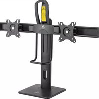
DMS-202 - Flat Screen Mount Gabor - Free user manual and instructions
Find the device manual for free DMS-202 Gabor in PDF.


| Product Type | Flat Screen Support / TV Wall Mount |
| Brand | Gabor |
| Model | DMS-202 |
| Compatible Screen Sizes | 32 to 65 inches (estimated) |
| VESA Compatibility | 100x100mm to 400x400mm (typical) |
| Maximum Weight Capacity | 50 kg (110 lbs, estimated) |
| Material | Steel with powder coating |
| Tilt Range | -5° to +15° (typical) |
| Swivel Range | ±90° (typical) |
| Rotation | 360° rotation (typical) |
| Distance from Wall | 50 to 500 mm (adjustable, typical) |
| Level Adjustment | ±3° after installation |
| Installation Type | Fixed to wall with provided hardware |
| Cable Management | Included cable covers |
| Power Supply | Not required |
| Cleaning Instructions | Wipe with dry or slightly damp cloth |
| Safety Notes | Ensure mounting surface can support weight; use appropriate anchors |
| Spare Parts Availability | Contact Gabor support |
| Warranty | 1 year (estimated) |
| Manual Languages | EN, and others available on notice-facile.com |
Frequently Asked Questions - DMS-202 Gabor
User questions about DMS-202 Gabor
0 question about this device. Answer the ones you know or ask your own.
Ask a new question about this device
Download the instructions for your Flat Screen Mount in PDF format for free! Find your manual DMS-202 - Gabor and take your electronic device back in hand. On this page are published all the documents necessary for the use of your device. DMS-202 by Gabor.
USER MANUAL DMS-202 Gabor
for 17 to 27 in. Screens
User Manual

natural_image
Technical line drawing of a mechanical lever assembly with two arms and a base (no text or symbols)Thank you for choosing Gabor.
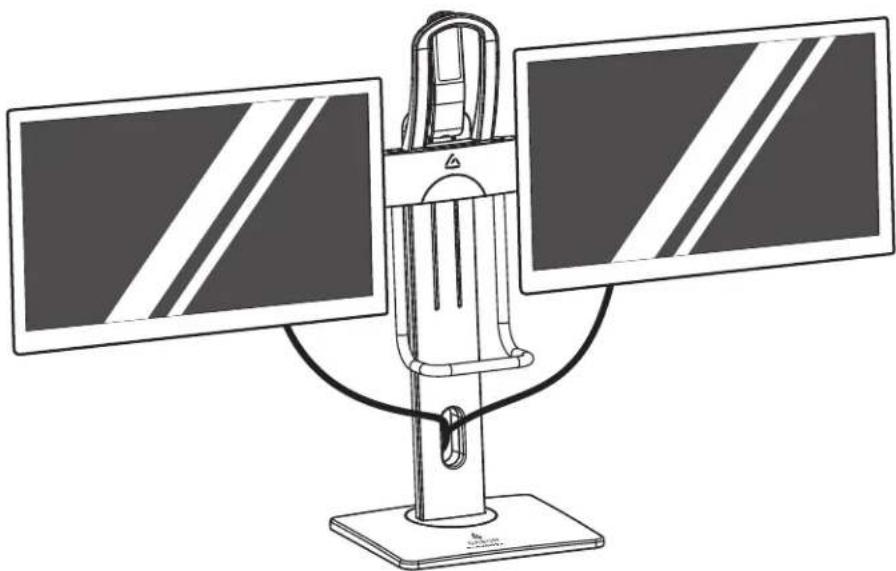
Gobor's sturdy Mainmast Dual Display Desktop Monitor Stand is a space and clutter saver for desks and workstations at home and in the office. This free-standing desk accessory can hold two monitors, each weighing up to 13.2 pounds, and allow you to adjust the height, swivel, and tilt for the perfect viewing angle. Standard VESA 75 × 75 and 100 × 100 patterns are compatible with most 17- to 27-inch monitors and the VESA plates rotate for both landscape and portrait orientation.
natural_image
Line drawing of a dual-panel computer monitor with two screens and a stand (no text or symbols)Safety Warnings
- Please read and follow the instructions, and keep this manual in a safe place.
- To avoid damage to this product, be careful not to overtighten or improperly thread any of the threaded fittings.
- Clean this product with only a soft, dry cloth.
- Mounting surfaces should be sturdy and flat. Do not install this product on a weak, uneven surface.
-
Do not install this product on an unsteady structure or one that is prone to vibration, has a chance of being impacted, or is susceptible to other movements. Reinforce the structure as necessary before installing this product.
-
Make sure everything is secure before proceeding to the next step.
- Do not exceed the maximum load capacity.
- Make sure that this product is intact and that there are no missing parts.
- If this product is missing hardware or there are defective parts, visit www.modebygabor.com or coll Customer Service at 212-594-2353.
- If you have safety concerns about installing this product, contact a qualified professional or installation contractor.
- All images are for illustrative purposes only.
Product Specifications
Monitor display size
17 to 27 in. (43.2 to 68.6 cm)
Maximum weight per monitor
13.2 lb. (6 kg)
VESA standards
75×75mm
100×100 mm
Monitor rotation
±180°
Monitor tilt
±45°
Column rotation
±40°
Column height adjustment
9.6 to 15.7 in. (24.5 to 40 cm)
Monitor height adjustment
range
6.1 in. (15.5 cm)
Weight (without monitors)
9.9 lb.(4.5 kg)
Package weight
11.6 lb. (5.2 kg)
Package dimensions (W × L × H)
17.1×10.8×4.4in.
(43.5×27.5×11.2cm)


Parts Included
| A 1X[5A04] | B 1XGliders | C 2XHaving/bracket/base/ lever front | D | E 1X4XF 1X | M-A 4XM4×12 mm screws | M-B 4XM3×12 mm screws | M-C 4XDS washer | |
G 2X | H 1X | I 1X | J 1X | K 1X | ||||
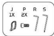
| L 2X | M 4XM4×5 mm screw-Hex bolt. | N | O 6X1XP 2XM6×12 mm screws | M6×8 mm screws | M6×12 mm screws | |||
| Q 1X | R 1X4 mm hex key Drioge do 5mm hex key | S 1X | T 1X6 mm hex key |
Assembling the Base
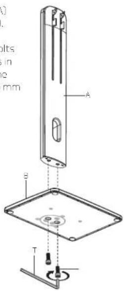
Fit the column (A) into the base (B).
Screw the hex bolts (L) into the holes in the bottom of the base using the 6 mm hex key (T).
Attaching the Lever
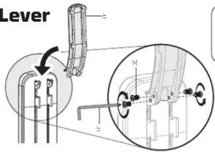
- Attach the lever back (E) to the height lock with the four screws (M). Use the screwdriver end of the 5 mm hex key (S) to tighten the screws until secure.
- Slide the lever front (F) up onto the lever back (E) so it locks in place.


natural_image
Technical line drawing of a mechanical component with an arrow indicating direction (no text or symbols)- Secure the lever front to the lever back with the M4×8 screw (N). Tighten it with the Phillips end of the 5 mm hex key (S).

Inserting the VESA Mounts into the Monitor Bar
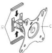
- Place two sliders (D) onto each mounting bracket (C) as pictured.
natural_image
Technical line drawing of a mechanical assembly with labeled components (no text or symbols)- Slide the mounting brackets into the monitor bars.
Note: Make sure the VESA plates are correctly oriented as pictured.

natural_image
Mechanical assembly diagram showing a bracket and housing component (no text or symbols)Assembling the Monitor Bar
- Slide the left and right sides of the monitor bar (G) onto the bridge (H).
- Make sure the bridge's arch is facing down.
- Use the M6×12 hex screws (O) to connect the two sides of the monitor bar with the bridge. Tighten with the 4 mm hex key (R) until secure.
- Hang the monitor bar with the bridge assembly on the column hooks.
- Slide the bridge clamp (I) into place under the bridge, attach it with hex bolt (Q) using the 5 mm hex key (S) until secure.

Attaching the Handles
- Slide the top handle (J) under the base of the lever to align the holes.
Note: The handle should curve toward the back of the stand.
- Secure the handle to the bridge with the M6×15 screws using the 5 mm hex key (S).
- Insert the lower hand grip (K) up through the two holes on the bottom of the bridge.

natural_image
Pure technical line drawing of a mechanical assembly without any text, numbers, or symbols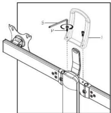
- Use the 4 mm hex key (R) to tighten the monitor arm set screws until secure.

Mounting the Monitor
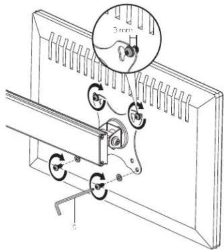
Before you attach the VESA plate, hand thread one of the M-A or M-B screws to determine which one fits your monitor. Make sure the screw is also not too long or too short. If the screw is too long, it may damage the display. If it's too short, it may not hold it.
100×100 VESA Pattern
- Slide M-C washers onto two screws, and thread the screws into your monitor's top two VESA holes. Leave about 3 mm between the washers, and the monitor.
- Hang the monitor on the VESA plate's two top notches with the two installed mounting screws.
Important! The washer should be between the screwhead and the VESA plate.
- Slide M-C washers onto two screws, and thread the screws into the bottom two VESA holes.
- Use the 5 mm hex key (K) to tighten all four screws until snug. Do not overtighten.


75 × 75 VESA Pattern
- Thread two screws into your monitor's top two VLSA holes. Leave about 3 mm between the screws and the monitor.
- Hang the monitor on the VESA plate's two keyholes with the two installed mounting screws.
Important! Do not use washers for the top screws on the 75×75 VESA pattern.

Cable Organization Monitor Tilt, Rotation, and Swivel
After the monitors are installed, keep your cables neat and organized by running them through the cable channel in the center column.
Adjusting the Monitor Height
Important! When adjusting monitor height, hold the handle and hand grip simultaneously. This will prevent the monitors from accidentally rising too quickly or tipping over.
-
With the monitors attached, hold the lower hand grip and press the lever towards the top handle.
-
Adjust the monitors to the desired height, and release the lever.

natural_image
Diagram of a mechanical device with a hand operating a lever, showing no text or symbols.Swivel
For optimum monitor position, the column swivels 40° to the left and right. Use the top and bottom handles to position the monitors at the preferred viewing angle.
Rotation
To change the orientation of a monitor from landscape to portrait, turn the monitor while it's attached to the VESA plate.

natural_image
Diagram showing a hand pressing a button on a screen with rotation arrows, no text or symbols present
natural_image
Diagram showing a hand interacting with a circular arrow icon on a rectangular platform (no text or symbols)Tilt
To adjust the viewing angles, tilt the monitors up or down by 45°. You may need to increase the tilt tension for larger and heavier monitors. Tighten the tilt tension screws by turning them clockwise with hex key (S). For smaller and lighter monitors, decrease the tilt tension by turning the tilt tension screws counterclockwise.


Three-Year Limited Warranty
This Gabor product is warranted to the original purchaser to be free from defects in materials and workmanship under normal consumer use for a period of three (3) years from the original purchase date or thirty (30) days after replacement, whichever occurs later. The warranty provider's responsibility with respect to this limited warranty shall be limited solely to repair or replacement, at the provider's discretion, of any product that foils during normal use of this product in its intended manner and in its intended environment. Inoperability of the product or part(s) shall be determined by the warranty provider. If the product has been discontinued, the warranty provider reserves the right to replace it with a model of equivalent quality and function.
This warranty does not cover damage or defect caused by misuse, neglect, accident, alteration, abuse, improper installation or maintenance. EXCEPT AS PROVIDED HEREIN, THE WARRANTY PROVIDER MAKES NEITHER ANY EXPRESS WARRANTIES NOR ANY IMPLIED WARRANTIES, INCLUDING BUT NOT LIMITED TO ANY IMPLIED WARRANTY OF MERCHANTABILITY OR FITNESS FOR A PARTICULAR PURPOSE. This warranty provides you with specific legal rights, and you may also have additional rights that vary from state to state.
To obtain warranty coverage, contact the Gabor Customer Service Department to obtain a return merchandise authorization ("RMA") number, and return the defective product to Gabor along with the RMA number and proof of purchase. Shipment of the defective product is at the purchaser's own risk and expense.
For more information or to arrange service, visit www.madebygabor.com or call Customer Service at 212-594-2353.
Product warranty provided by the Gradus Group.
www.grodusgroup.com
Gabor is a registered trademark of the Gradus Group. © 2021 Gradus Group LLC. All Rights Reserved.

GABOR®
A Gradus Group Brand
- Thank you for choosing Gabor.
- Safety Warnings
- Product Specifications
- Assembling the Base
- Attaching the Lever
- Inserting the VESA Mounts into the Monitor Bar
- Assembling the Monitor Bar
- Attaching the Handles
- Mounting the Monitor
- 100×100 VESA Pattern
- × 75 VESA Pattern
- Cable Organization Monitor Tilt, Rotation, and Swivel
- Adjusting the Monitor Height
- Swivel
- Rotation
- Tilt
- Three-Year Limited Warranty
Brand : Gabor
Model : DMS-202
Category : Flat Screen Mount