Vintage Pre ADDAC712 - Audio Preamplifier ADDAC System - Free user manual and instructions
Find the device manual for free Vintage Pre ADDAC712 ADDAC System in PDF.


| Product Type | Eurorack Synthesizer Module |
| Model | Vintage Pre ADDAC712 |
| Brand | ADDAC System |
| Width | 8 HP |
| Depth | 30 mm (approx.) |
| Height | 3U (128.5 mm) |
| Weight | 100 g |
| Power Supply | +12V 50 mA, -12V 50 mA (via Eurorack bus) |
| Main Functions | Vintage-style preamplifier with gain control, EQ section, and output level |
| Inputs | 1x audio input (3.5 mm jack) |
| Outputs | 1x audio output (3.5 mm jack) |
| Controls | Gain knob, EQ knobs (bass, mid, treble), output level knob |
| Safety | Low voltage; handle with care to avoid short circuits; do not exceed power supply ratings |
| Maintenance | Wipe with a dry, soft cloth; avoid liquid cleaners |
| Spare Parts & Repairability | Contact ADDAC System for spare parts; module is not user-serviceable |
| General Information | Designed for use in Eurorack synthesizer systems; provides warm vintage coloration |
Frequently Asked Questions - Vintage Pre ADDAC712 ADDAC System
User questions about Vintage Pre ADDAC712 ADDAC System
0 question about this device. Answer the ones you know or ask your own.
Ask a new question about this device
Download the instructions for your Audio Preamplifier in PDF format for free! Find your manual Vintage Pre ADDAC712 - ADDAC System and take your electronic device back in hand. On this page are published all the documents necessary for the use of your device. Vintage Pre ADDAC712 by ADDAC System.
USER MANUAL Vintage Pre ADDAC712 ADDAC System
ADDAC System
Instruments for Sonic Expression Est.2009
INTRODUCING
ADDAC712
VINTAGE
PREAMP
USER'S GUIDE, REVO1
December.2022

ADDAC
System
From Portugal with Love!
DESCRIPTION
ADDAC712 is a dual channel discrete gain staging amplifier, based on a famous discrete preamp board from the 70's used in some legendary equipment.
What caught our attention was the character of it's clipping and resulting saturation/distortion.
The module can be used with modular signals to add a distortion/fuzz character or as a preamp for an external source such as a line source, keyboard, guitar...
It's also a great side companion for our ADDAC711 Balanced Inputs.
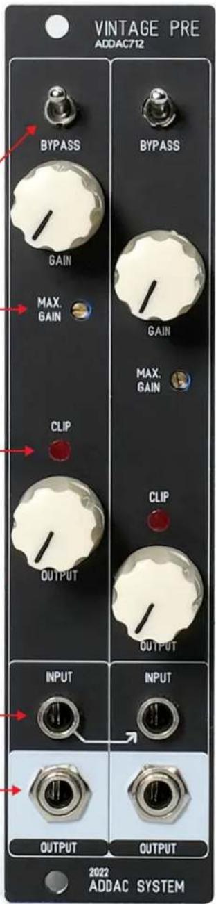
At the top an On/Off [BYPASS] switch routes the signal into the Effect (Up: Active) or to the bottom output gain stage (Down: Bypassed).
The amount of amplification is set by the [GAIN] control, the maximum amount of amplification can be set by the user using the [MAX GAIN] trimmer.
Up to ±5.5v the incoming signal will keep it's integrity, beyond this point saturation will start to increase.
At aprox. ±6v a hard clipping will start to occur, this clipping also has a particular quality that at extreme levels it drifts the audio 0v bias reference, moving it upwards which results are similar to a Gate effect.
In the middle, an x2 opamp based output gain stage with a clipping led, which monitors the clipping at the output, and an [OUTPUT] control to set the output volume.
Having the top and middle gain stages provides flexibility allowing the user to completely distort the signal on the top stage and tame it's output level with the second stage.
At the bottom, Input and Output for both channels (Left input is normalled into Right input).
This module will also be available as a full DIY kit..
Tech Specs:
6HP
4 cm deep
40mA +12V
40mA -12V
ADDAC712
VINTAGE PREAMP SIGNAL FLOW DIAGRAM

flowchart
graph TD
    A["INPUT 1"] --> B["PREAM GAIN CONTROL"]
    B --> C["BYPASS ON OFF"]
    C --> D["OUTPUT GAIN CONTROL"]
    D --> E["OUTPUT 1"]
    F["INPUT 2"] --> G["PREAM GAIN CONTROL"]
    G --> H["BYPASS ON OFF"]
    H --> I["OUTPUT GAIN CONTROL"]
    I --> J["OUTPUT 2"]
    K["MAXIMUM GAIN CONTROL"] --> B
    L["CLIPPING LED MONITOR"] --> D
    M["CLIPPING LED MONITOR"] --> J
For feedback, comments or problems please contact us at: addac@addacsystem.com
CONTROLS DESCRIPTION

Brand : ADDAC System
Model : Vintage Pre ADDAC712
Category : Audio Preamplifier