ASV-1 - Measurement MGL Avionics - Free user manual and instructions
Find the device manual for free ASV-1 MGL Avionics in PDF.

User questions about ASV-1 MGL Avionics
0 question about this device. Answer the ones you know or ask your own.
Ask a new question about this device
Download the instructions for your Measurement in PDF format for free! Find your manual ASV-1 - MGL Avionics and take your electronic device back in hand. On this page are published all the documents necessary for the use of your device. ASV-1 by MGL Avionics.
USER MANUAL ASV-1 MGL Avionics
Vega ASV-1
Altimeter, Airspeed (ASI) and Vertical Speed Indicator (VSI)
Operating Manual – English 1.00
Introduction
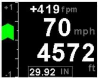
The ASV-1 is a 2 1/4" sunlight readable encoding altimeter, airspeed and wide range vertical speed indicator.
The altimeter contains an internal high accuracy 24 bit digital altitude sensor which calculates altitude from -1000 ft up to a maximum of 35000 ft. The ASV-1 outputs various formatted RS232 serial data protocols compatible with serial input transponders such as that from Garmin, Magellan, Northstar, Trimble, Microair etc. The altimeter can display altitude in feet or meters and local pressure can be set in millibars or inches of mercury
The VSI indicator can be displayed in either feet/minute (ft/min) or meters/second (m/s). The VSI can be calibrated by the user once the instrument has been installed in the aircraft.
Airspeed is based on the pressure generated by a pitot tube system and a static port is provided as well for use by high speed aircraft. The ASV-1 instrument measures airspeed from 16mph to 250mph and is well suited to slower aircraft due to very good sensitivity and linearity at low air speeds. Airspeed can be indicated in statute miles per hour (mph), kilometers per hour (km/h) or nautical miles per hour (kts). The ASV-1 also provides a programmable Vs and Vne airspeed alarm output. ASI sensitivity can be calibrated by the user to cater for errors caused by pitot tube placement.
In addition, the ASV-1 provides an encoder test function, flight timer since takeoff and records the maximum airspeed reached. The ASV-1 provides a parallel Gillham code interface when used in conjunction with the MGL Avionics CNV-ALT.
1 Features
- Large 1.8" high resolution 160x128, sunlight readable, wide viewing angle, 1000 cd/m2 TFT LCD display
- An internal high accuracy 24 bit digital altitude sensor calculates altitude from -1000 ft up to a maximum of 35000 ft (-304m to 10668m)
- The ASV-1 outputs various formatted RS232 serial data protocols compatible with serial input transponders such as that from Garmin, Magellan, Northstar, Trimble, Microair etc.
- Provides a parallel Gillham code interface for transponders when used in combination with the MGL Avionics CNV-ALT
• Built in encoder test function - The altimeter can display altitude in feet or meters
- Local pressure can be set in millibars or inches of mercury
- Contains a wide range VSI indicator from +/-20 ft/min to as high as +/-10000 ft/min
- VSI units can be in feet/minute (ft/min) or in meters/second (m/s)
- Measures airspeed from 16mph to 250mph and is well suited to slow aircraft due to very good sensitivity and linearity at low air speeds
- Includes a flight timer since takeoff
- Airspeed units can be set to miles per hour (mph), kilometer per hour (km/h) or nautical miles per hour (kts)
- Contains a programmable Vs and Vne airspeed alarm output
- Records maximum airspeed reached in permanent memory
- Standard 2 1/4" aircraft enclosure (can be front or rear mounted)
- Rotary control plus 2 independent buttons for easy menu navigation and user input
- Wide input supply voltage range of 8 to 30V DC with built in voltage reversal and over voltage protection for harsh electrical environments
• 1 year limited warranty
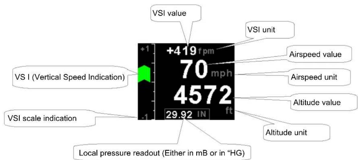
2 ASV-1 Layout
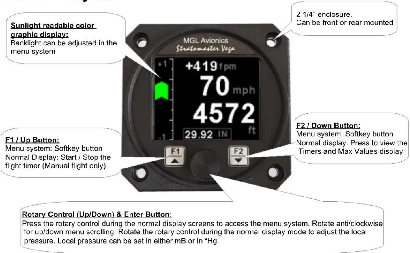
3 Main Display
Vega ASV-1 Operating Manual Page 4
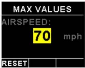
3.1 Maximum Airspeed display
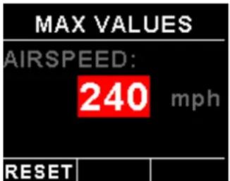
This display can be accessed by pressing the F2/Down button during the normal display mode. Press the F1/Up button when the max values display is showing to reset the maximum values to the current airspeed.
Note: The maximum airspeed is stored in non-volatile memory and is recalled on power-up.
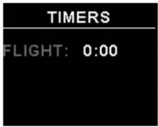
3.2 Start / Stop flight display


Press the F1/Up button during the normal display mode to manually start/stop a flight. This key is only active if the ASV-1 is setup to select the manual flight option under the "TIMERS" setup menu.
Vega ASV-1 Operating Manual Page 5
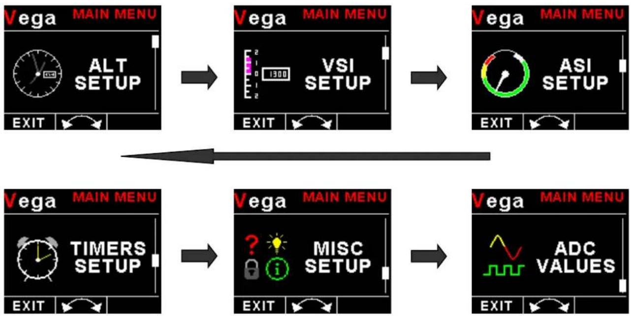
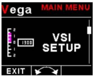
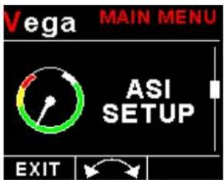
4 Menu System
Press the rotary control button during the normal display mode to enter the menu system. Use the rotary control to navigate through the menu system.
flowchart
graph TD
A["Vega MAIN MENU\nALT SETUP\nEXIT"] --> B["Vega MAIN MENU\nVSI SETUP\nEXIT"]
B --> C["Vega MAIN MENU\nASI SETUP\nEXIT"]
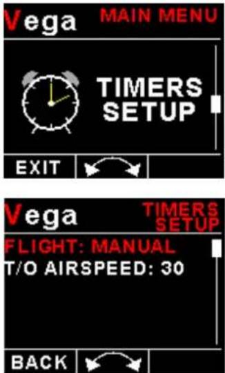
C --> D["Vega MAIN MENU\nTIMERS SETUP\nEXIT"]
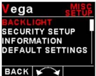
D --> E["Vega MAIN MENU\nMISC SETUP\nEXIT"]
E --> F["Vega MAIN MENU\nADC VALUES\nEXIT"]
4.1 Exiting the menu system
Press the F1/Up button to exit the menu system when the "EXIT" soft key is shown. All changes made during navigation of the menu system will be saved in non-volatile memory upon exiting. The instrument will not save any changes if you remove power before exiting the menu system.
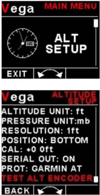
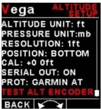
4.2 ALT Setup (Altitude Setup)
Vega ASV-1 Operating Manual Page 6
Altitude Unit:
Select if you want the altitude displayed in ft (feet) or m (meters).
Pressure Unit:
Select if you want the local pressure displayed in mB (millibars) or "Hg (inches of mercury).
Resolution:
Select the resolution of the altitude value, a selection of 1,10,25 or 100 ft or m can be selected.
Position:
Select whether you want the altitude display on the top or on the bottom of the main display.
Cal:
On the rear of your ASV-1 instrument you will find the calibration factor that has been determined to ensure the most accurate reading of your altimeter. This is the value that should be entered here. Should you have access to an accurate reference you may use this function to calibrate your altimeter. Before you do this, ensure that your calibrated and certified reference is set to the local pressure of 1013.25mB (29.92"HG). Your altimeter has been calibrated by the factory to an accuracy of +/- one mB or approximately +/- 30 ft (10m) at sea level.
Serial Out:
Select "ON" to enable the RS232 serial altitude output. This formatted serial RS232 message can be directly interfaced to various RS232 serial input transponders. If a parallel Gillham output is required then a CNV-ALT can be purchased from your MGL Avionics distributor to convert the RS232 output to a parallel Gillham output.
Prot:
Select the protocol of the serial RS232 output message. The protocol can be selected between GARMIN AT, Magellan, Northstar / Garmin, Trimble / Garmin, MGL Avionics and Microair UAV. Please note that the baud rate is automatically adjusted according to which protocol is selected. The output format is as follows. The message contains the current pressure altitude with a fixed reference to 1013.25mB (29.92 inches mercury). All protocols use 8 databits, no parity, and 1 stop bit. The message is outputted once a second.
| Protocol Baud Rate | Message format Example | ||
| Garmin AT 1200 | #AL, space, | +/-, five altitude digits rightjustified zero padded, T+25, checksum,carriage returnThe checksum is a simple modulo 256 sumof the binary values of the individualcharacters. The checksum is sent as twocharacters in hexadecimal format | #AL +02372T+25DF[CR] |
| Magellan 1200 # | MGL, +/-, five | altitude digits right justifiedzero padded, T+25, checksum, carriagereturnThe checksum is a simple modulo 256 sumof the binary values of the individualcharacters. The checksum is sent as twocharacters in hexadecimal format | $MGL+02372T+2513[CR] |
| Northstar,Garmin | 4800 ALT | space, five altitude digits right justifiedzero padded, carriage return | ALT 02372[CR] |
| Trimble,Garmin | 9600 ALT | space, five altitude digits right justifiedzero padded, carriage return | ALT 02372[CR] |
| MGL Avionics 96 | 00 ALT, +/-, | five altitude digits right justifiedzero padded ,1013.25mB (29.92"Hg)referenced, C, +/-, five altitude digits rightjustified zero padded (corrected to localpressure), L, local pressure setting in | ALT+02372C+02372L1013+0000XCA[CR] |
Vega ASV-1 Operating Manual Page 7
| millibars, +/-, four digit VSI reading right justified zero padded in ft/min, X, checksum, carriage returnThe checksum is a simple modulo 256 sum of the binary values of the individual characters. The checksum is sent as two characters in hexadecimal format | |||
| Microair UAV 9600 STX,a,=, five altitude digits right justified zero padded, ETX | [STX]a=02372[ETX] | ||
| STX=0x02ETX=0x03CR=0x0D | |||
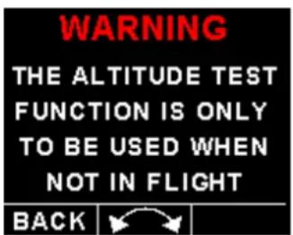
Test Alt Encoder:
This is a handy function to test the ASV-1 transponder interface once the installation has been completed. The serial output will output specific altitudes which can then can be used to test the serial RS232 output and the parallel gillham output if using a CNV-ALT converter. The ASV-1 will resume the normal output of the indicated altitude upon exiting the test function.
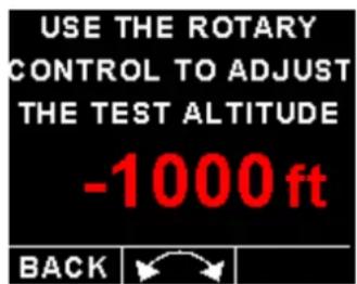
The following codes are outputted:
| Altitude D4 A1 | A2 A4 | B1 B2 | B4 C1 | C2 C4 | |||||
| -1000ft 0 0 0 0 | 0 0 0 | 0 1 0 | |||||||
| -900ft 0 0 0 0 | 0 0 0 | 1 1 0 | |||||||
| -700ft 0 0 0 0 | 0 0 1 | 1 0 0 | |||||||
| -400ft 0 0 0 0 | 0 0 1 | 0 1 1 | |||||||
| -200ft 0 0 0 0 | 0 1 1 | 0 0 1 | |||||||
| 800ft 0 0 0 0 | 1 1 0 | 0 0 1 | |||||||
| 2800ft 0 0 0 1 | 1 0 0 | 0 0 1 | |||||||
| 6800ft 0 0 1 1 | 0 0 0 | 0 0 1 | |||||||
| 14800ft | 0 1 | 1 0 0 0 | 0 0 0 1 | ||||||
| 30800ft | 1 1 | 0 0 0 0 | 0 0 0 1 |
Each altitude reporting code line must be tested for integrity of connection if at any time the aircraft connections to the transponder or altitude data source have been removed and reconnected. Integrity of the connections may be verified by performing a test of mode C function of the transponder system.
Warning: Do not use this function while in flight as incorrect altitude information will be sent to the transponder.
4.3 VSI Setup (Vertical Speed Indicator Setup)
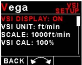
VSI Display:
Select if you want the VSI display to be shown on the altitude "TAPE" display. The VSI display is always shown on the altitude "CLASSIC" display.
VSI Unit:
Select if you want the VSI to be displayed in "ft/min" (feet/minute) or "m/s" (meters/second).
Scale:
Select the VSI scale most suited for your aircraft.
VSI Cal:
This is a function that is used to calibrate your VSI to read exact rates of climb or decent. This function works as a percentage of initial reading. The default setting for this function is 100%. Increasing this value increases the VSI reading and decreasing the value decreases the reading.
Suggested VSI calibration method
After you have installed the instrument, perform a calibration flight. This should be done in very calm conditions. Turbulence and thermal activity will make accurate calibration impossible. Many areas have ideal conditions during early mornings or late afternoons. Place the instrument in ft/min for ease of calibration. Take your aircraft to a few thousand feet above ground and start a glide with a low power setting. Take a stopwatch and when the glide is stable (stable VSI reading) start the stopwatch. Take note of your altimeter reading at the same time. Continue the stable glide for one minute exactly. After the minute has finished, take another reading of your altimeter.
Example:
VSI reading during stable glide: -400 ft/min
Start altitude: 2500 ft.
End altitude: 2050 ft.
In the above example the VSI is under reading by about 12%. Set your VSI calibration to 112% to cancel out the error.
4.4 ASI Setup (Airspeed Setup)
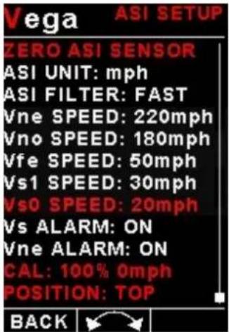
Zero ASI Sensor:
This setup allows your instrument to measure the zero airspeed reading of the airspeed sensor and set a calibration value internally for this. This is equivalent to some mechanical airspeed indicators that have an adjustment to set the needle to zero when the aircraft is not moving. You would use this function occasionally if you see an airspeed reading when the aircraft is at rest. This may be caused by aging of the built in pressure sensor or related electronics. When this function is performed make sure that there is no air flow into the pitot tube as this would result in an incorrect internal calibration.
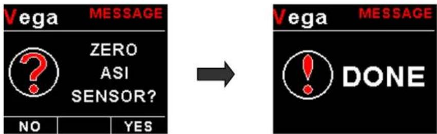
flowchart
graph LR
    A["ZERO ASI SENSOR?"] --> B["NO"]
    A --> C["YES"]
    D["Vega"] --> E["DONE"]
    E --> F["→"]
    F --> G["VEGA MESSAGE"]
ASI Unit:
Select if you want the ASI to be displayed in mph (statute miles per hour), km/h (kilometers per hour) or kts (nautical miles per hour).
ASI Filter:
This function can be used to select the signal filter time constant. Selections are "NONE", "FAST" or "SLOW". This selection influences the rate at which your ASI can change its reading. If you have an installation that suffers from strong turbulence at the pilot tube, select "slow". If you have a very clean airflow in front of the pilot tube you can select "fast" which will give you a faster response to airspeed changes.
Vega ASV-1 Operating Manual Page 10
Vne Speed: (Max Exceed Speed)
Enter you maximum speed you aircraft should not exceed.
Vno Speed: (Max Maneuvering Speed)
Enter your maximum maneuvering speed.
Vfe Speed: (Max Flap Speed)
Enter the maximum speed that is permissible with the flaps extended.
Vs1 Speed: (Min Safe Speed, Normal)
Enter your minimum safe speed for normal flight of your aircraft
Vs0 Speed: (Min Safe Speed, Landing)
Enter your minimum safe speed for landing your aircraft
Vs Alarm:
This enables or disables Vs Alarm.
Vne Alarm:
This enables or disables the VNE alarm.
Cal:
During the factory calibration a factor has been determined and entered here that will give you accurate airspeed, provided your pitot tube is not influenced by pressure effects caused by airflow around your airframe. The calibration is displayed in % of the reading, you can increase or decrease the reading if required to help cancel out under or over reading of the airspeed indicator on your aircraft. The original calibration factor has been written onto the back of your instrument.
Position:
Select whether you want the airspeed display on the top or on the bottom of the main display.
Vega ASV-1 Operating Manual Page 11
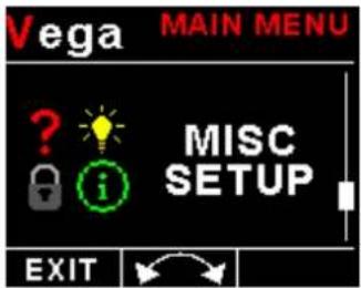
4.5 Timers Setup
FLIGHT:
Select whether you want the ASV-1 to automatically detect a flight or whether the pilot must press the F1/Up button to start/stop a flight. We recommend you select automatic flight detection.
T/O AIRSPEED:
This menu option is only shown if the "DETECT" flight mode is selected. Enter the takeoff airspeed threshold that you want the flight timer to start incrementing.
Vega ASV-1 Operating Manual Page 12
4.6 MISC Setup (Miscellaneous Setup)
Backlight:
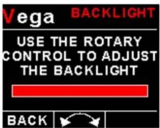
Select this menu option to adjust the backlight brightness.
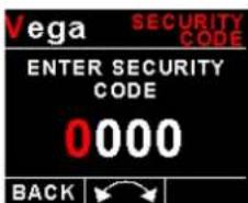
Security Setup:
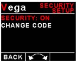
Select this menu option if you want to password protect the menu system.


Information:
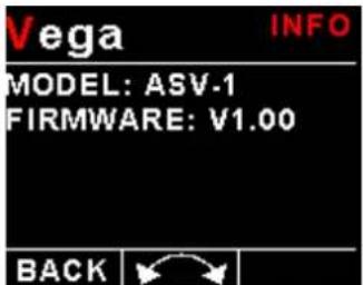
This menu option displays information about the unit.
Vega ASV-1 Operating Manual Page 13
Default Settings:
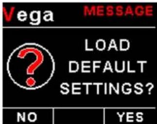
Select this menu option to reset all the settings to factory defaults.
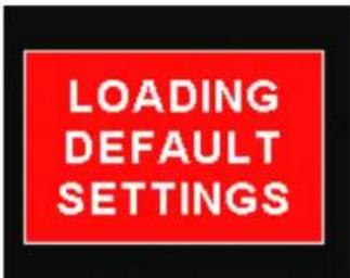
4.7 ADC Values
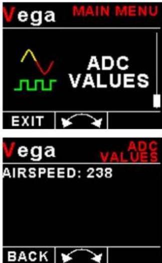
This menu displays the ADC value that have been read from the airspeed pressure sensor.
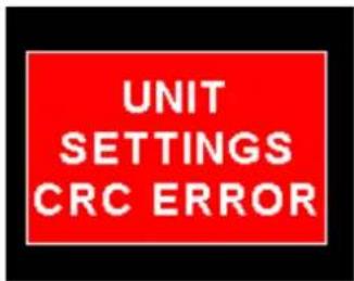
5 Loading factory default settings
Press and hold the F1/Up button and rotary control during power up to load the pre-programmed factory default settings. The following screen will be displayed:
Factory default settings can also be loaded in the Miscellaneous setup menu.
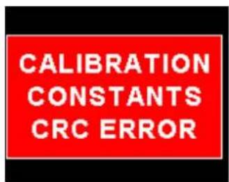
6 Error Messages
Unit settings CRC error. Load default settings to restore to factory defaults. If the error message still persists then it could possibly be a non-volatile memory failure in which case the instrument will then have to be returned to the factory.
Calibration constants CRC error. The instrument could possibly have a non-volatile memory failure in which case the instrument will then have to be returned to the factory.

Max Values CRC error. Load default settings to restore to factory defaults. If the error message still persists then it could possibly be a non-volatile memory failure in which case the instrument will then have to be returned to the factory.
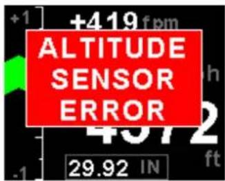
Altitude sensor error. The instrument could have a faulty altitude sensor in which case the instrument will then have to be returned to the factory.
7 ASV-1 Specifications
| Operating Temperature Range -10°C to 60°C (14°F to 140°F) | |
| Storage Temperature Range -20°C to 80°C (-4°F to 176°F) | |
| Humidity <85% non-condensing | |
| Power Supply | 8 to 30Vdc SMPS (switch mode power supply) with built in 33V over voltage and reverse voltage protection |
| Current Consumption | Approx. 73mA @ 13.8V (backlight highest setting), 33mA @13.8V (backlight lowest setting) |
| Display | 1.8" 160x128 pixel active matrix TFT display.1000 cd/m2Sunlight readable with anti-glare coatingLED Backlight is user configurable |
| Alarm Output | Open collector transistor switch to groundMaximum rating 0.5A |
| Altitude sensor ADC resolution 24 bit | |
| Dimensions see Vega series dimensional drawing | |
| Enclosure 2 1/4" ABS, black in color, front or rear mounting. Flame retardant. | |
| Weight Approx. 120 grams (Instrument excluding cables) | |
| Non-volatile memory storage 100000 write cycles | |
| Altimeter range -1000ft to 35 000ft (-304m to 10668m) | |
| Altitude units ft or m | |
| Pressure units InHG or mB | |
| VSI range +-20ft/min to +-10000ft/min | |
| VSI units ft/min or m/s | |
| Airspeed ADC resolution 12 bit | |
| Airspeed range | 16mph to 250mph |
| Airspeed resolution | 1 mph |
| Measurement accuracy | +/-1% at 85mph nominal |
| Serial Port | RS232 voltage levels |
8 Operating the alarms
The alarm output can be used to switch an external alarm indicator. The external alarm switch is an open collector transistor switch to ground with a maximum rating of 0.5A DC. It is possible to wire the alarm contacts of several Stratomaster instruments in parallel should this be desired. To avoid false activation of the alarms, the alarm function is only active 10 seconds after the instrument has powered up.
9 Firmware Upgrading
The ASV-1 can be upgraded in the field by connecting the RS232 port to a PC and running the firmware update program. Note that only the RS232 port can be used to upgrade the firmware.
Please see the Vega firmware upgrading document for more information.
10 Installation
Connect a pitot tube to the "pressure port" and if required connect the static port.
Connect the static port to a suitable static air pressure line. If you have a slow aircraft or an aircraft where the internal cabin pressure does not change during flight and is equivalent to the outside air pressure you may find that it is not required to connect a static port. Most small aircraft such as ultralights or microlights do not require a connection to a static port. In these cases, simply leave the static port open. Ensure however that the static port does not receive pressurized air due to the forward movement of the aircraft. Be especially critical of your pod or panel if you do not use a static port. Any build up of a pressure differential due to ram air or suction can lead to large errors of the indicated airspeed and altitude. Static ports are usually mounted at a strategic position on the rear side of the aircraft fuselage for faster, pressurized aircraft.
Suitable connection hose for both pitot tube and static port can be obtained from a hardware store or even a pet shop. Good quality tubing is often used for fish tanks and it has just the right diameter.
Please note that this kind of tubing is not advised for pressurized aircraft. In this case you would need to obtain aircraft grade tubing of suitable diameter. You would also have to use hose clamps to fasten the hose onto the ASV-1 pitot and static ports. The ASV-1 allows you to calibrate the airspeed reading. This is done under the "AIRSPEED SETUP" menu item. The main reason for this is to be able to remove errors introduced due to the airflow around your aircraft which may have an effect on your pitot tube pressure.
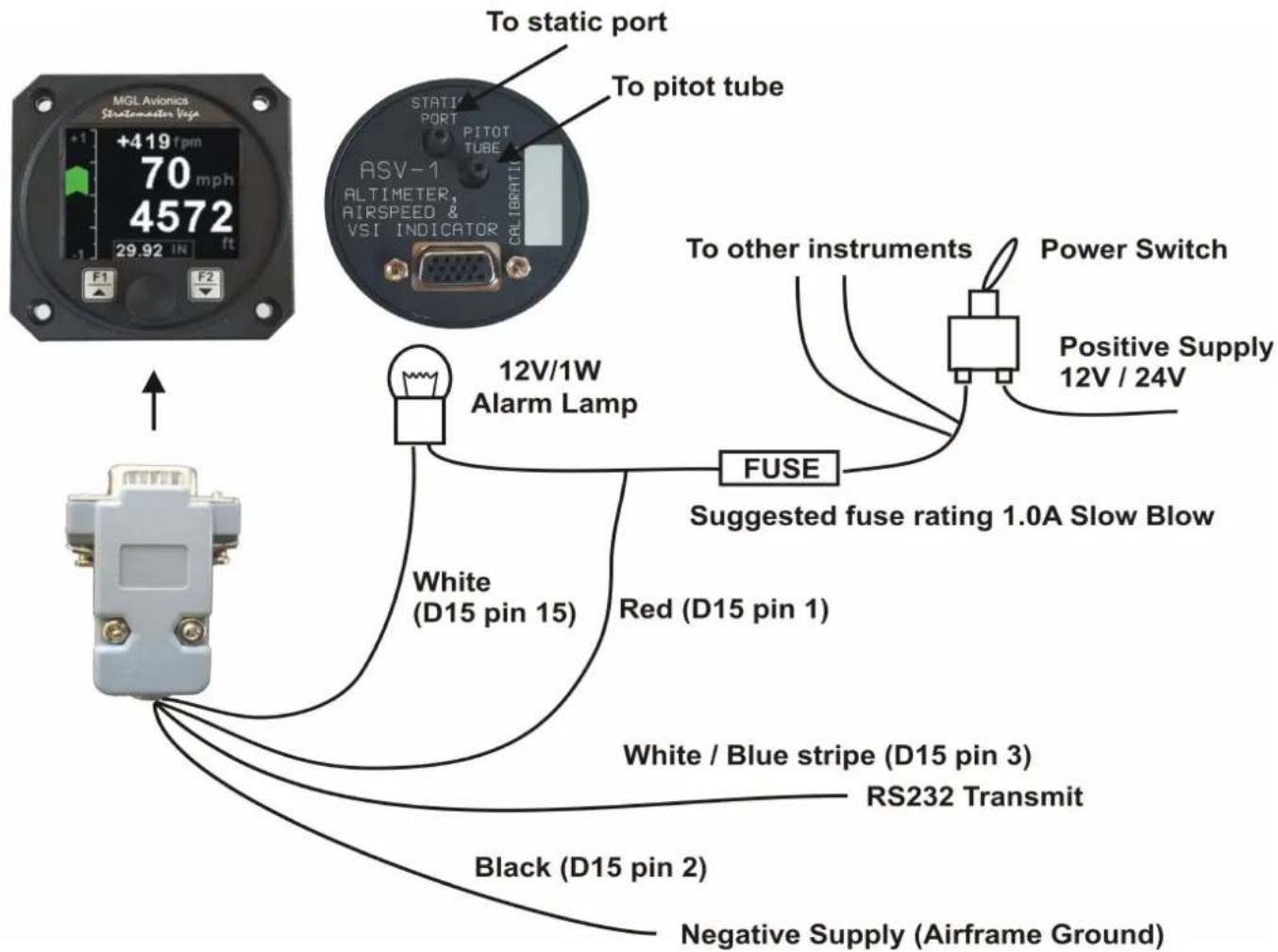
10.1 Connection Diagram
The use of an external 1A fuse is recommended. Connect the supply terminals to your aircrafts power supply. The ASV-1 can be used on both 12V and 24V without the use of any pre-regulators. Ensure that the supply voltage will not drop below 8V during operation as this may result in incorrect readings.
10.2 Pressure Port Dimensions
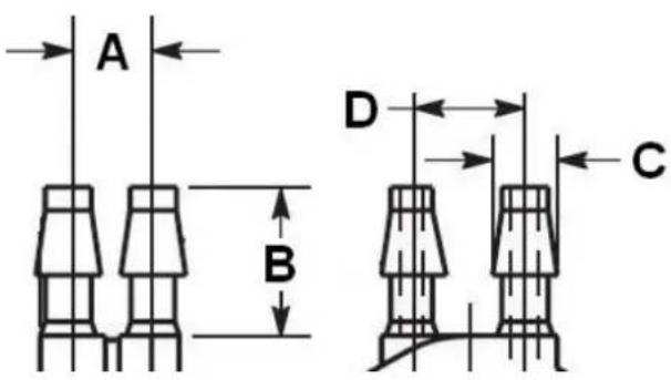
| Inches | Millimeters | |||
| Min | Max | Min | Max | |
| A | 0.248 | 0.278 | 6.30 | 7.06 |
| B | 0.420 | 0.440 | 10.67 | 11.18 |
| C | 0.182 | 0.194 | 4.62 | 4.93 |
| D | 0.310 | 0.330 | 7.87 | 8.38 |
10.3 ASV-1 Cable connections
Main connector (D15 connector: Unit Female, Cable Male)
| D15 Pin Color Function | ||
| 1 Red 8 | -30Vdc power via power switch / circuit breaker and fuse. | |
| 2 Black | Ground. | |
| 3 White | Blue Stripe | RS232 Transmit data (Firmware upgrading / RS232 Altitude output) |
| 4 - RS232Receive data (Firmware upgrading) | ||
| 15 White | Alarm Output (Open collector) | |
11 Cleaning
The unit should not be cleaned with any abrasive substances. The screen is very sensitive to certain cleaning materials and should only be cleaned using a clean, damp cloth.
Warning: The ASV-1 is not waterproof, serious damage could occur if the unit is exposed to water and/or spray jets.
12 Warranty
This product carries a warranty for a period of one year from date of purchase against faulty workmanship or defective materials, provided there is no evidence that the unit has been mishandled or misused. Warranty is limited to the replacement of faulty components and includes the cost of labor. Shipping costs are for the account of the purchaser.
Damage as a result of applying excessive pressure to the static pressure port are excluded from warranty.
Note: Product warranty excludes damages caused by unprotected, unsuitable or incorrectly wired electrical supplies and or sensors, and damage caused by inductive loads.
13 Disclaimer
Operation of this instrument is the sole responsibility of the purchaser of the unit. The user must make themselves familiar with the operation of this instrument and the effect of any possible failure or malfunction.
This instrument is not certified by the FAA. Fitting of this instrument to certified aircraft is subject to the rules and conditions pertaining to such in your country. Please check with your local aviation authorities if in doubt. This instrument is intended for ultralight, microlight, homebuilt and experimental aircraft. Operation of this instrument is the sole responsibility of the pilot in command (PIC) of the aircraft. This person must be proficient and carry a valid and relevant pilot's license. This person has to make themselves familiar with the operation of this instrument and the effect of any possible failure or malfunction. Under no circumstances does the manufacturer condone usage of this instrument for IFR flights.
IMPORTANT NOTICE:
You must make your own determination if the products sold by MGL Avionics are safe and effective for your intended applications. MGL Avionics makes no representations or warranties as to either the suitability of any of the products we sell as to your particular application or the compatibility of any of the products we sell with other products you may buy from us or anywhere else, and we disclaim any warranties or representations that may otherwise arise by law. Also, we offer no specific advice on how to install any of the products we sell other than passing along anything that may have been provided to us by the manufacturer or other issues. If you are in need of further information or guidance, please turn to the manufacturer, FAA Advisory Circulars and guidance materials, the Experimental Aircraft Association, or other reputable sources.
The manufacturer reserves the right to alter any specification without notice.
Other instruments in the Stratomaster Vega series
AHRS-1 Artificial Horizon and Magnetic Compass Indicator
ALT-5 Altimeter and Vertical Speed Indicator (VSI)
ASI-4 Airspeed Indicator (ASI)
ASV-1 Altimeter, Airspeed (ASI) and Vertical Speed Indicator (VSI)
EMS-1 Engine Monitoring System
FF-4 Fuel Computer
INFO-1 Information Display (G-force meter, RTC, Outside Air Temperature (OAT), Volts and Current display)
MAG-1 Magnetic Compass Indicator
MAP-3 Manifold Pressure and RPM Indicator
RPM-1 Universal Engine / Rotor RPM Indicator
TC-4 4-Channel Thermocouple (EGT/CHT) Indicator
TP-3 Universal Temperature and Pressure Indicator