TC-4 - Measurement MGL Avionics - Free user manual and instructions
Find the device manual for free TC-4 MGL Avionics in PDF.


| Product Type | 4-Channel Thermocouple Indicator (EGT/CHT) |
| Display | 1.8" TFT LCD, 160x128 pixels, 1000 cd/m², sunlight readable, wide viewing angle |
| Temperature Measurement Range | -100°C to 1200°C (-148°F to 2192°F) depending on probe type |
| Supported Probe Types | J, K, E type thermocouples |
| Number of Channels | 1 to 4 (configurable for EGT and/or CHT) |
| Display Modes | 5 screens: Vertical Bars, Horizontal Bars, Numeric, EGT/CHT Bars, plus Trend Graph and Max Values |
| Special Functions | Engine leaning mode (peak EGT identification), Cruise mode (relative temperature trends) |
| Alarm Output | Open collector transistor switch to ground, 0.5A max rating |
| Data Source | Internal thermocouple amplifier or external RDAC via CAN bus |
| Power Supply | 8-30V DC SMPS with built-in overvoltage (33V) and reverse voltage protection |
| Current Consumption | Approx. 73mA @13.8V (high backlight), 33mA @13.8V (low backlight) |
| Weight | Approx. 120 g (instrument only, excluding cables) |
| Dimensions | 2 1/4" diameter (standard aircraft enclosure) |
| Mounting | Front or rear mount |
| Operating Temperature | -10°C to 60°C (14°F to 140°F) |
| Connections | D15 (power, RS232, CAN, alarm) and D9 (thermocouple inputs) |
| Accuracy | +/- 5°C typical (with quality probes) via cold junction compensation and linearization tables |
| Warranty | 1 year limited warranty |
| Cleaning Instructions | Use a clean, damp cloth; no abrasive substances. Unit is not waterproof. |
Frequently Asked Questions - TC-4 MGL Avionics
User questions about TC-4 MGL Avionics
0 question about this device. Answer the ones you know or ask your own.
Ask a new question about this device
Download the instructions for your Measurement in PDF format for free! Find your manual TC-4 - MGL Avionics and take your electronic device back in hand. On this page are published all the documents necessary for the use of your device. TC-4 by MGL Avionics.
USER MANUAL TC-4 MGL Avionics
Vega TC-4
One to four channel thermocouple (EGT/CHT) indicator
Operating Manual – English 1.00
bar
| Category | Value | |---|---| | EGT | 724 | | CHT | 169 | | Green Bar (1) | Green | | Yellow Bar (2) | Yellow | | Red Bar (1) | Red | | Cyan Bar (2) | Cyan |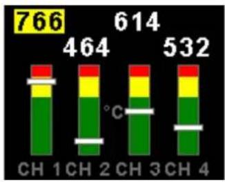
bar_stacked
| Category | Value | |---|---| | CH 1 | 766 | | CH 2 | 464 | | CH 3 | 614 | | CH 4 | 532 | The chart displays the total counts for each category, with each bar segmented into three colored layers representing different components of the total. The horizontal lines indicate the temperature (°C) between consecutive bars.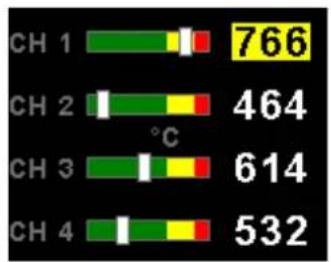
bar
| Category | Value | |---|---| | CH 1 | 766 | | CH 2 | 464 | | CH 3 | 614 | | CH 4 | 532 |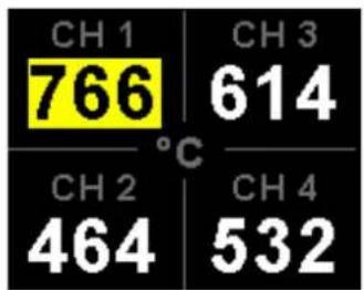
Introduction
The TC-4 is a 2 1/4" sunlight readable 4 channel thermocouple color display instrument.
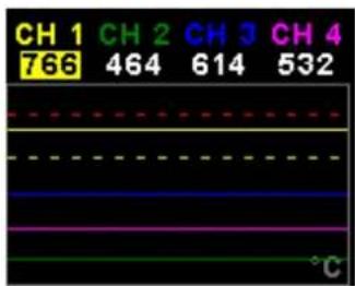
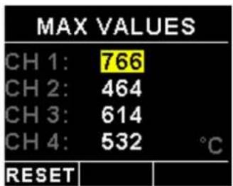
The instrument can be configured for 5 different temperature display screens. The display can be configured to group EGTs and CHTs to common settings or each thermocouple channel can be independently displayed with individual programmable high alarm and probe type. The TC-4 also has a trend graph and maximum values display screen.
The TC-4's high accuracy is due to its built in thermocouple linearization curves and cold junction compensation techniques. Temperature probes can be common J, K or E type thermocouple probes as used in CHT and EGT senders. Temperatures can be displayed in degrees Celsius or degrees Fahrenheit from -100^ to 1200^ (-148°F to 2192°F).
The TC-4 also features a built in engine leaning facility which allows the pilot to optimize the fuel mixture according to peak EGT temperatures as well as a cruise mode facility to provide instant identification of changing EGT/CHT trends.
The TC-4 can also be interfaced via the CAN bus to an external RDAC unit (Remote Data Acquisition Unit). This allows for easier installation as the RDAC unit is normally mounted in the engine compartment.
1 Features
- Large 1.8" high resolution 160x128, sunlight readable, wide viewing angle, 1000 cd/m2 TFT LCD display
- 5 different temperature display screens
• Supports J, K and E type thermocouple probes
• Temperatures can be displayed in °C or °F from -100°C to 1200°C (-148°F to 2192°F)
• High accuracy: Built in thermocouple linearization curves and cold junction compensation - Records maximum temperatures reached for each channel
- Includes a trend graph display of each thermocouple channel
• Engine leaning function according to peak EGT temperatures
• Engine cruise mode to instantly identify changing EGT/CHT trends
• External RDAC interfacing via the CAN bus - Standard 2 1/4" aircraft enclosure (can be front or rear mounted)
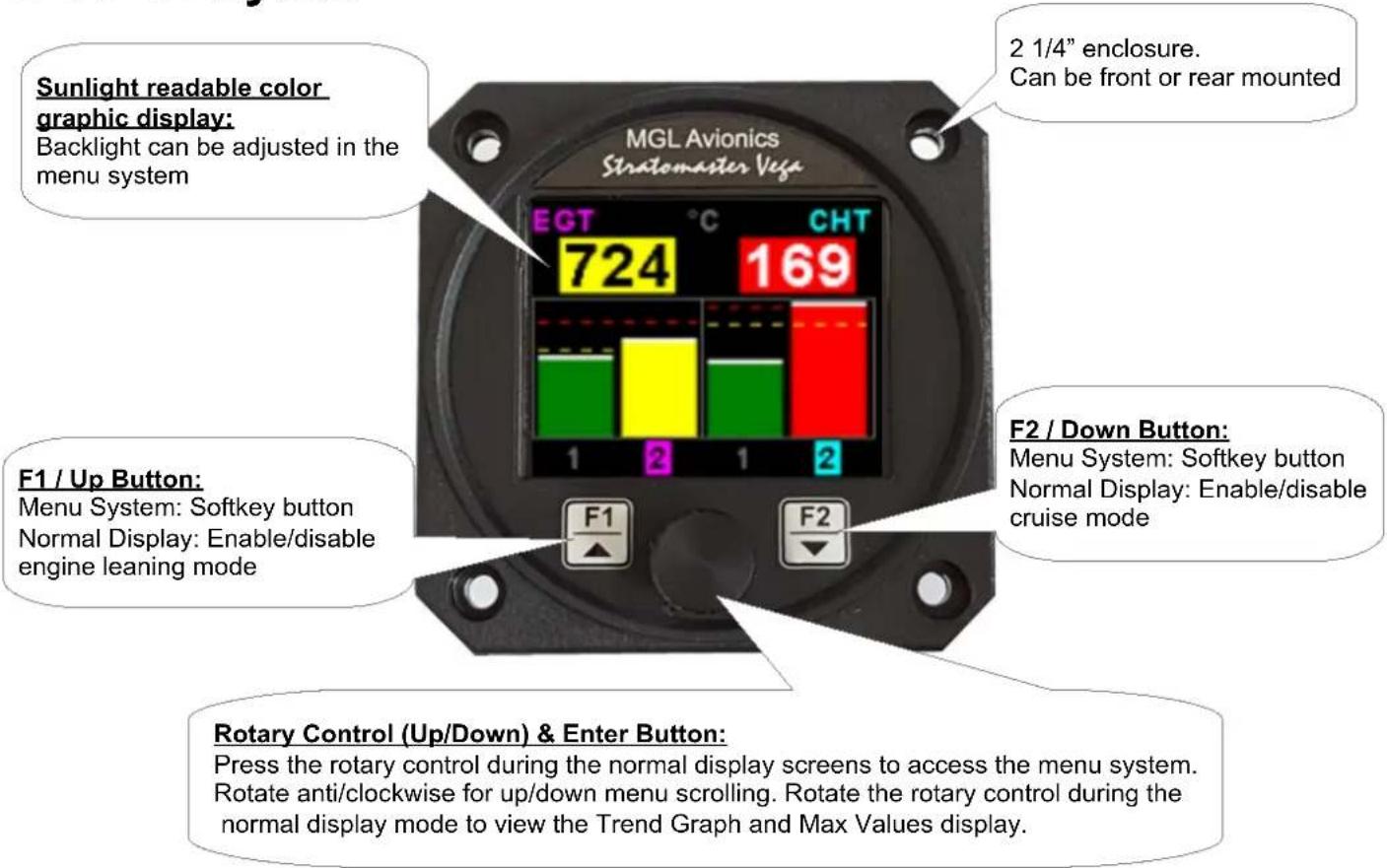
- Rotary control plus 2 independent buttons for easy menu navigation and user input
- An external output activates when a high alarm condition has been reached
- Wide input supply voltage range of 8 to 30V DC with built in voltage reversal and over voltage protection for harsh electrical environments
• 1 year limited warranty
Vega TC-4 Operating Manual Page 2
2 TC-4 Layout
3 Main Displays
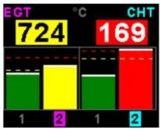
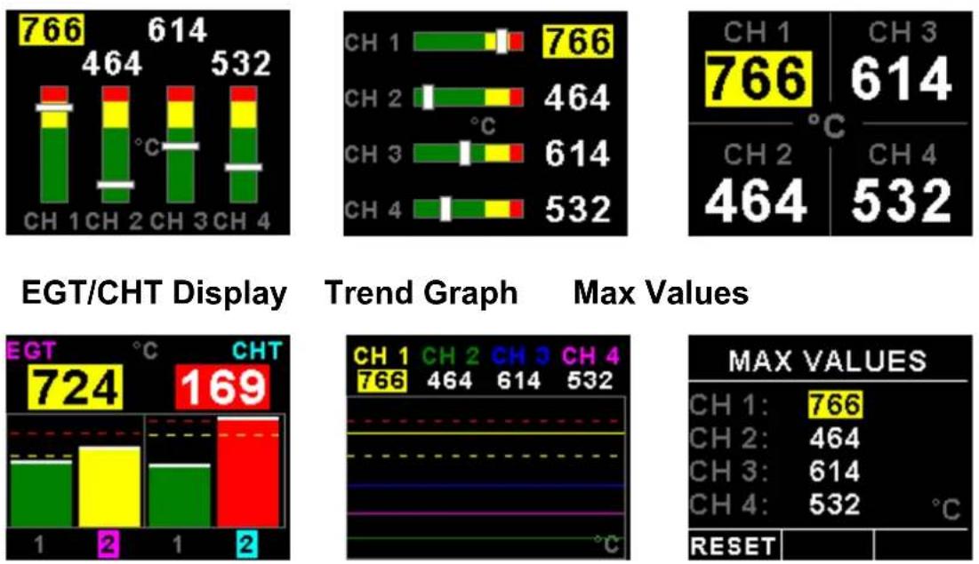
The TC-4 has 5 different temperature display screens. The main display screen can be selected in the "TC SETUP" menu. The Trend graph and Max Values display can be selected by rotating the rotary control.
Vertical Display Horizontal display Numeric Display
Vega TC-4 Operating Manual Page 3
3.1 Trend Graph display
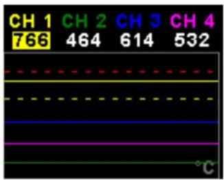
This display can be accessed by rotating the rotary control during the normal display mode. The trend graph displays the last 100 seconds of temperature readings.
3.2 Maximum Values display
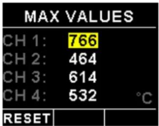
This display can be accessed by rotating the rotary control during the normal display mode. Press the F1/Up button when the max values display is showing to reset the maximum values to the current temperature values.
Note: The maximum values are stored in non-volatile memory and are recalled on power-up.
3.3 Engine leaning mode
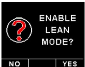
EGT information is also very useful for fuel mixture control. As the fuel mixture is leaned, so the exhaust gasses get hotter. This rise in temperature is a sign of increased combustion efficiency as the optimum mixture setting is approached. If the leaning progresses past a certain point however, the temperature will begin to drop. This temperature drop is the result of reduced energy output from the diminished fuel flow. The best operating mixture for aircraft engines is in the vicinity of this peak EGT reading. The TC-4 has a special Leaning mode, which easily identifies the peak EGT condition allowing you to adjust your fuel mixture for best performance.
bar
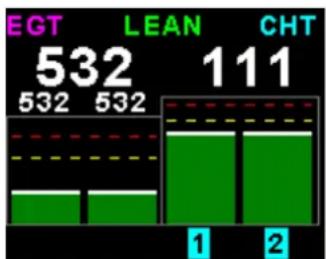
| Group | Value | |---|---| | EGT | 532 | | LEAN | 111 | | CHT | 111 |Fuel mixture should be adjusted once you have decided on a suitable cruise power setting (typically 70%). Press the F1/Up button on the main display to enable the engine leaning mode. The "LEAN" label is displayed at the top of the main display to clearly differentiate it from the normal operating mode.
As the fuel mixture is slowly leaned past the point at which the temperature begins to drop (by more than 10^ C/ 15^ F), the absolute EGT temperatures will change to show the EGT reading relative to this peak. The sequential order as each cylinder peaks is also shown.
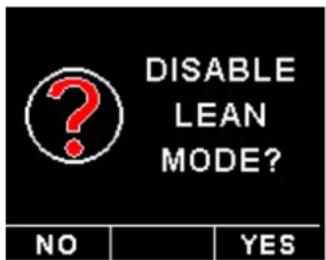
Leaning mode can be canceled by pressing the F1/Up button again.
Vega TC-4 Operating Manual Page 4
3.4 Engine cruise mode
bar
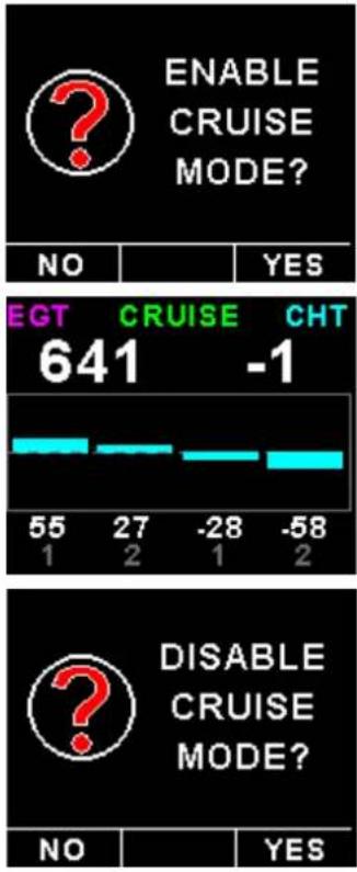
| Category | Value | |---|---| | ENABLE CRUISE MODE? | 641 | | EGT | -1 | | CRUISE | 27 | | CHT | -28 | | DISABLE CRUISE MODE? | 55 | | DISABLE CRUISE MODE? | -58 | | NO | YES |Once in the cruise, press the F2/Down button to enable the Cruise Mode. The "CRUISE" label is displayed at the top of the main display to clearly differentiate it from the normal operating mode. All EGT and CHT readings are immediately sampled as reference temperatures for the cruise.
The display then shows EGT and CHT values relative to this reference temperature.
Leaning mode can be canceled by pressing the F2/Down button again.
4 Menu System
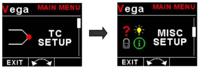
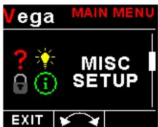
Press the rotary control button during the normal display mode to enter the menu system. Use the rotary control to navigate through the menu system.
flowchart
graph LR
    A["Vega MAIN MENU"] --> B["TC SETUP"]
    B --> C["EXIT"]
    D["Vega MAIN MENU"] --> E["MISC SETUP"]
    E --> F["EXIT"]
    G["?"] --> H["i"]
    H --> I["?"]
    I --> J["Lightbulb icon"]
    J --> K["MISC SETUP"]
4.1 Exiting the menu system
Press the F1/Up button to exit the menu system when the "EXIT" soft key is shown. All changes made during navigation of the menu system will be saved in non-volatile memory upon exiting. The instrument will not save any changes if you remove power before exiting the menu system.
Vega TC-4 Operating Manual Page 5
4.2 TC Setup (Thermocouple Setup)
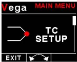
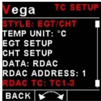
The TC-4 has 2 different "TC SETUP" menus depending on the display style selected.
4.2.1 EGT/CHT TC Setup menu options
Style:
Select the display style of the main display. Options include Vertical Bars, Horizontal Bars, Numeric values only and EGT/CHT bars.
Temp Unit:
Select whether you want the temperature to be displayed in degrees Celsius (°C) or degrees Fahrenheit (°F).
EGT Setup
Select this menu option to setup the EGT thermocouples. See EGT/CHT Setup menu option below.
CHT Setup
Select this menu option to setup the CHT thermocouples. See EGT/CHT Setup menu option below.
Data:
Select the data source of the themocouples. Options include internal (using the internal thermocouple amplifier and Vega connector) or from an optional external RDAC unit.
RDAC Address:
Select the CAN address of the external RDAC unit.
RDAC TC:
Select the thermocouple group that you would like to measure from the RDAC. Options include TC1-4, TC5-8, TC9-12.
Vega TC-4 Operating Manual Page 6
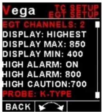
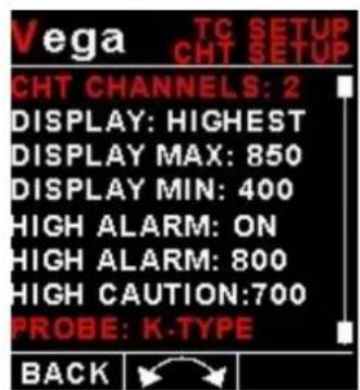
EGT/CHT Setup menu option
EGT / CHT Channels:
Select the number of EGT or CHT channels you want to use. Choices are from 1 to 4. The temperature display will configure itself to make best possible use of the available display size. Please note that the minimum number of EGT & CHT channels that can be displayed is 1 and the maximum number of EGT and CHT channels that can be displayed is 4.
Display:
A selection between "HIGHEST" or "SCANNING" can be selected. If "HIGHEST" is selected then the current highest thermocouple temperature is displayed. If "SCANNING" is selected then the unit will cycle through each thermocouple at a one second interval.
Display Max:
Select the maximum temperature that you want the EGT/CHT bargraph to show. This can give you increased display resolution.
Display Min:
Select the minimum temperature that you want the EGT/CHT bargraph to show. This can give you increased display resolution.
High Alarm:
This enables or disables the EGT/CHT high alarm.
High Alarm:
Enter the temperature threshold for when the high alarm must be activated. Any temperature above this value will activate the alarm.
High Caution:
Enter the temperature value for the high caution.
Probe:
Select if you are using a K-type, J-type or E-type thermocouple probe for this channel. All probes supplied by MGL Avionics are K-Type. J-types are sometimes used with American made CHT probes. All EGT probes are K-type. E-type probes are seldom used.
Vega TC-4 Operating Manual Page 7
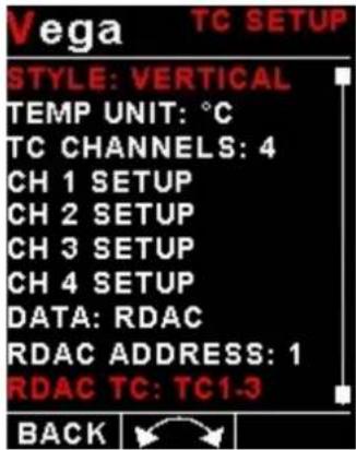
4.2.2 Vertical/Horizontal and Numeric menu options
Style:
Select the style of the main display. Options are Vertical Bars, Horizontal Bars, Numeric only and EGT/CHT bars.
Temp Units:
Select whether you want the temperature to be displayed in degrees Celsius (°C) or degrees Fahrenheit (°F).
TC Channels:
Select how many TC channels must be monitored by the TC-4.
CH 1 Setup / CH 2 Setup / CH 3 Setup / CH 4 Setup
Select this menu option to setup the theromcouple channels. See CH1 to CH4 Setup menu option below.
Data:
Select the data source of the themocouples. Options include internal (using the internal thermocouple amplifier and Vega connector) or from an optional external RDAC unit.
RDAC Address:
Select the CAN address of the RDAC unit.
RDAC TC:
Select the thermocouple group that you would like to measure from the RDAC. Options include TC1-4, TC5-8, TC9-12.
CH1 to CH4 Setup menu option
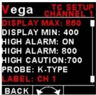
Only "CHANNEL 1" Setup is shown below, follow the same steps for Channel 2, 3 & 4
Vega TC-4 Operating Manual Page 8
Display Max:
Select the maximum temperature that you want the bargraph to show. This can give you increased display resolution.
Display Min:
Select the minimum temperature that you want the bargraph to show. This can give you increased display resolution.
High Alarm:
This enables or disables the channels high alarm.
High Alarm:
Enter the temperature threshold for when the high alarm must be activated. Any temperature above this value will activate the alarm.
High Caution:
Enter the temperature value for the high caution.
Probe:
Select if you are using a K-type, J-type or E-type thermocouple probe for this channel. All probes supplied by MGL Avionics are K-Type. J-types are sometimes used with American made CHT probes. All EGT probes are K-type. E-type probes are seldom used.
Label:
Enter a label to suit your channel so you can identify it easily.
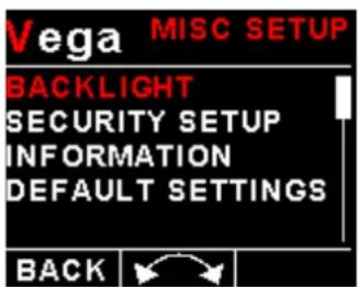
4.3 MISC Setup (Miscellaneous Setup)
Vega TC-4 Operating Manual Page 9
Backlight:
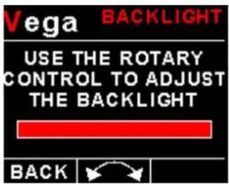
Select this menu option to adjust the backlight brightness.
Security Setup:
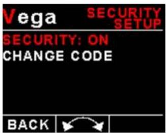
Select this menu option if you want to password protect the menu system.
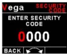
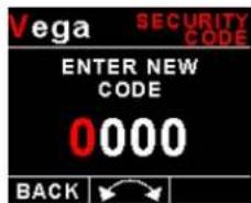
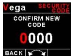
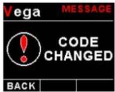
Information:
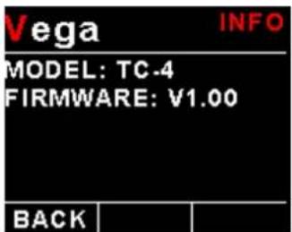
This menu option displays information about the unit.
Default Settings:
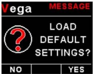
Select this menu option to reset all the settings to factory defaults.
5 Loading factory default settings
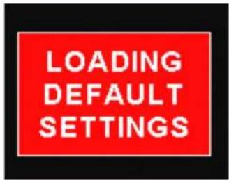
Press and hold the F1/Up button and rotary control during power up to load the pre-programmed factory default settings. The following screen will be displayed:
Factory default settings can also be loaded in the Miscellaneous setup menu.
6 Error Messages
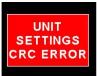
Unit settings CRC error. Load default settings to restore to factory defaults. If the error message still persists then it could possibly be a non-volatile memory failure in which case the instrument will then have to be returned to the factory.
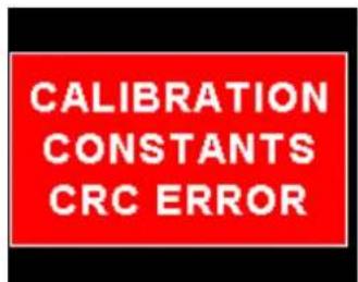
Calibration constants CRC error. The instrument could possibly have a non-volatile memory failure in which case the instrument will then have to be returned to the factory.
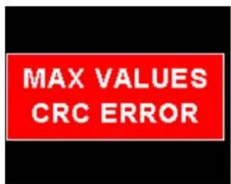
Max Values CRC error. Load default settings to restore to factory defaults. If the error message still persists then it could possibly be a non-volatile memory failure in which case the instrument will then have to be returned to the factory.
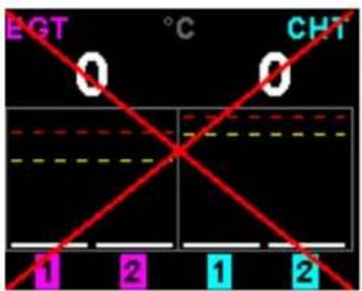
The red cross over the display means the TC-4 has lost communications with the external RDAC unit. Check the wiring between the TC-4 instrument and the RDAC unit. This error message is only available when the external RDAC is selected as the thermocouple data source.
7 TC-4 Specifications
| Operating Temperature Range -10°C to 60°C (14°F to 140°F) | |
| Storage Temperature Range -20°C to 80°C (-4°F to 176°F) | |
| Humidity <85% non-condensing | |
| Power Supply | 8 to 30Vdc SMPS (switch mode power supply) with built in 33V over voltage and reverse voltage protection |
| Current Consumption | Approx. 73mA @ 13.8V (backlight highest setting), 33mA @13.8V (backlight lowest setting) |
| Display | 1.8" 160x128 pixel active matrix TFT display.1000 cd/m2Sunlight readable with anti-glare coatingLED Backlight is user configurable |
| Alarm Output | Open collector transistor switch to groundMaximum rating 0.5A |
| ADC 12 bit | |
| Dimensions see Vega series dimensional drawing | |
| Enclosure 2 1/4" ABS, black in color, front or rear mounting. Flame retardant. | |
| Weight Approx. 120 grams (Instrument excluding cables) | |
| Non-volatile memory storage 100000 write cycles | |
| Thermocouples J-type, K-type and E-Type | |
| Measurement range | TC-4 Internal amplifierK-Type: -100°C to 1200°C (-148°F to 2192°F)J-Type: -100°C to 1100°C (-148°F to 2012°F)E-Type: -100°C to 800°C (-148°F to 1472°F) |
| Technology | Fully cold junction compensated using a precision internal temperature reference and built in thermocouple linearization tables |
| Measurement accuracy | +/- 5 degrees typical over full temperature range, subject to quality of probe used. We recommend MGL Avionics EGT and CHT probes |
| Inputs Differential, can use grounded and isolated probes | |
| Common mode voltage range -2V to +3V | |
8 Operating the alarms
The alarm output can be used to switch an external alarm indicator. The external alarm switch is an open collector transistor switch to ground with a maximum rating of 0.5A DC. It is possible to wire the alarm contacts of several Stratomaster instruments in parallel should this be desired. To avoid false activation of the alarms, the alarm function is only active 10 seconds after the instrument has powered up.
9 Firmware Upgrading
The AHRS-1 / MAG-1 can be upgraded in the field by connecting the RS232 port to a PC and running the firmware update program. Note that only the RS232 port can be used to upgrade the firmware.
Please see the Vega firmware upgrading document for more information.
10 Installation
The TC-4 provides for up to 4 thermocouple inputs for use with EGT and CHT probes. K, J as well as E-type probes can be used. K types are used for EGT probes while CHT probes can either be J or K type. E-type probes are seldom used. Probe types are selected in the various "TC SETUP" menus of the TC-4.
Important: Incorrect selection of probe type will lead to an incorrect temperature display.
The TC-4 will accept both grounded and isolated thermocouple probes. Your only consideration in case of the more common grounded configurations is that you need to ensure that the thermocouple mounting position (exhaust flange, etc.) is at the same electrical potential as the negative supply line of the TC-4.
The thermocouple amplifier is a precision device providing full cold junction compensation. This results in very accurate measurements providing you install high quality probes. Here are some guidelines:
EGT Probes: Select probes that are made from 316 stainless steel and that use glass-fiber insulated conductors. Teflon insulated conductors as found in many cheap probes introduce errors as the insulation melts moving the measuring point towards the mounting bolt which transfers a lot of heat to the exhaust material. This results in under reading probes. Stay away from probes that use simple plastic heat shrink sleeving – it does not last. Choose probes that use a generous amount of stainless steel spring as strain relief. The bolt itself should be stainless steel as well or it will rust very quickly.
CHT Probes: These are made from washers to fit spark-plug bases. Temperatures are considerably lower so most thermocouple cables will work without problems. The biggest area of concern should be the connection of the thermocouple cable to the washer. This often breaks after the spark plug has been changed a few times. Choose a probe that is suitably reinforced at this point for a long and trouble free life.
EGT and CHT probes supplied by MGL Avionics are of the highest quality. We recommend that you consider using our probes if at all possible.
EGT and CHT probes use wire made from iron and other basic metals. As a result these probes are not able to withstand much flexing of the wires due to engine vibrations. Avoid making nice looking coils or similar constructions that will result in excessive vibration or flexing of the wire. Route the cables from the probe points tightly along suitable engine mounting points eliminating any chance of unnecessary wire flexing during engine operation.
Warning: Four stroke engines produce much hotter exhaust gases compared to two stroke engines. Do not use EGT probes made from lower grade stainless steel (for example 310), these probes will not withstand the high temperatures and can fail as the metal gets very soft at 800 degrees C. Many four strokes (such as the Rotax 912) will produce exhaust gases of up to 850 degrees C.
Extending the leads of thermocouple probes:
Thermocouple leads as used with the EGT and CHT probes can be extended either with ordinary copper cable or with special K-Type extension cable. The choice of either depends on your desired accuracy. If it is possible in your installation to ensure that both ends of a copper extension cable will be at the same temperature (or very close), then it is quite possible to use the copper cable. In most open-air installations this will be the case. Should this not be possible or you require best possible accuracy at all times, you can obtain a special K-type extension cable. This cable is made from the same metals as your probes cable and uses ordinary plastic sleeving as insulation. In either case, ensure that the cable is not routed close to sources of electromagnetic interference of any kind. The voltages present in this cable are very small and are subject to changes applied by external fields. This can lead to false temperature indications. You can check your installation by using a hand-held transmitter, such as an air band radio. If you transmit a signal, no change in temperature reading should occur.
Notes on thermocouple connections using the supplied harness:
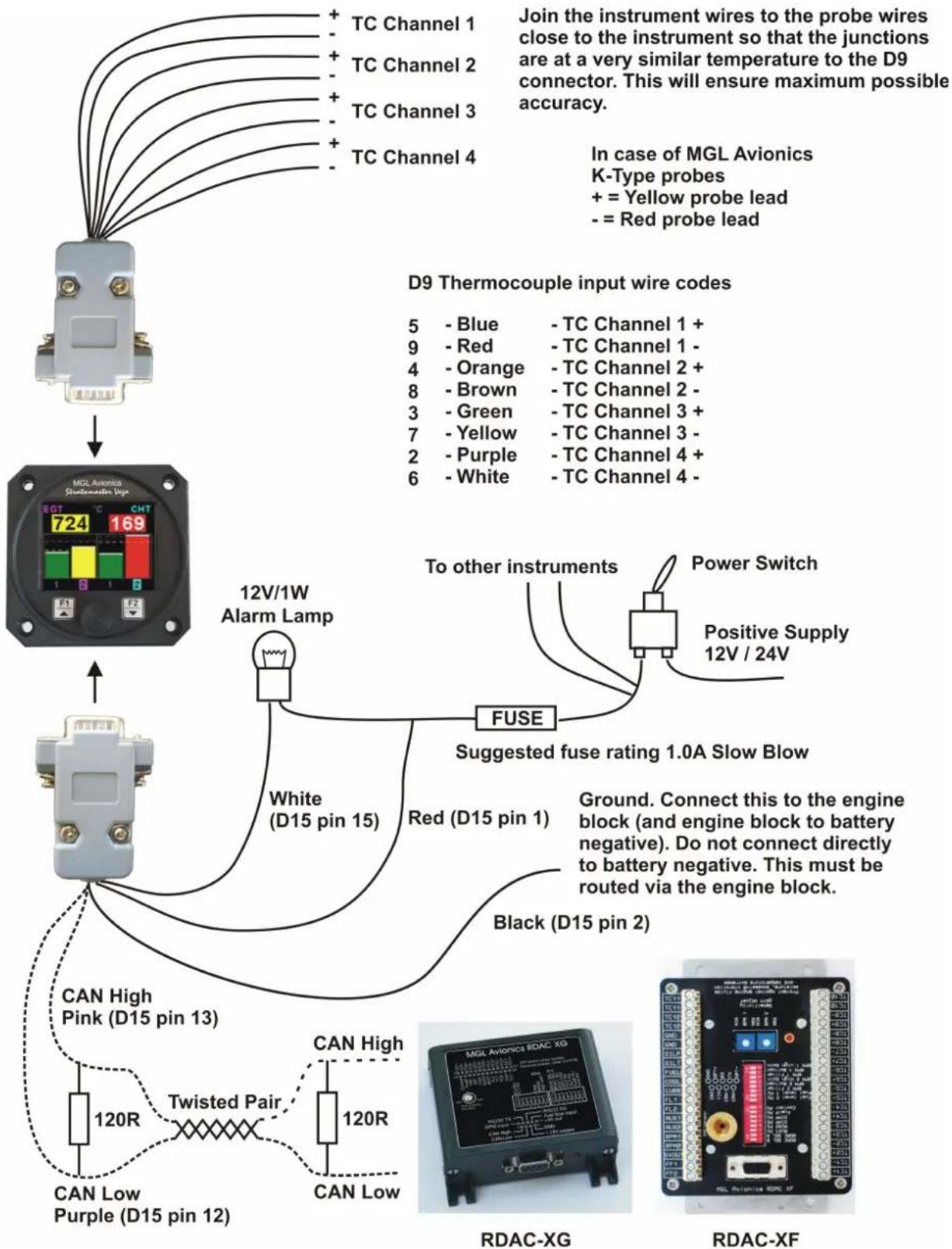
For maximum accuracy of the thermocouple temperature measurement, please ensure that either end of the harness cable (where used for thermocouple probes) is at fairly even temperature (minimise the temperature difference between the connector side of the cable and the side where you connect the thermocouple). If required, shorten the cable to fulfil this need.
Note: Connect the TC-4 ground to the engine block, and the engine block to battery negative. Do not connect the TC-4 ground directly to the battery negative. This must be routed via the engine block.
Note: Always install EGT probes starting on Channel 1 followed by the CHT probes without skipping any channels in between.
External RDAC Connection:
The TC-4 can use an external RDAC unit as the source for the thermocouples. Using an external RDAC may be beneficial as it will reduce the wiring from the engine compartment to the cockpit. Only the CAN High and CAN Low connections need to be made between the RDAC unit and the TC-4 in order for this to work. Select "RDAC" for the data in the TC Setup menu if using the external RDAC option.
10.1 TC-4 Cable connections
Main connector (D15 connector: Unit Female, Cable Male)
| D15 Pin Color Function | ||
| 1 Red 8- | 30Vdc power via power switch / circuit breaker and fuse. | |
| 2 Black | Ground. Connect the ground to the engine block, and the engine block to the battery negative. Do not connect the TC-4 ground directly to the battery negative. This must be routed via the engine block. | |
| 3 - RS23 | 2 Transmit data (Firmware upgrading) | |
| 4 - RS23 | 2 Receive data (Firmware upgrading) | |
| 12 Purple CAN Low (Used for optional external RDAC) | ||
| 13 Pink CAN High (Used for optional external RDAC) | ||
| 15 White Alarm Output (Open collector) | ||
Thermocouple (EGT/CHT) connector (D9 connector: Unit Male, Cable Female)
In case of MGL Avionics K-Type probes + = Yellow probe lead, - = Red probe lead
| D9 Female Pin | Color | Function |
| 5 | Blue | TC Channel 1 + |
| 4 | Orange | TC Channel 2 + |
| 3 | Green | TC Channel 3 + |
| 2 | Purple | TC Channel 4 + |
| 9 | Red | TC Channel 1 - |
| 8 | Brown | TC Channel 2 - |
| 7 | Yellow | TC Channel 3 - |
| 6 | White | TC Channel 4 - |
10.2 Connection Diagram
The use of an external 1A fuse is recommended. Connect the supply terminals to your aircrafts power supply. The TC-4 can be used on both 12V and 24V without the use of any pre-regulators. Ensure that the supply voltage will not drop below 8V during operation as this may result in incorrect readings.
11 Cleaning
The unit should not be cleaned with any abrasive substances. The screen is very sensitive to certain cleaning materials and should only be cleaned using a clean, damp cloth.
Warning: The TC-4 is not waterproof, serious damage could occur if the unit is exposed to water and/or spray jets.
12 Warranty
This product carries a warranty for a period of one year from date of purchase against faulty workmanship or defective materials, provided there is no evidence that the unit has been mishandled or misused. Warranty is limited to the replacement of faulty components and includes the cost of labor. Shipping costs are for the account of the purchaser.
Note: Product warranty excludes damages caused by unprotected, unsuitable or incorrectly wired electrical supplies and or sensors, and damage caused by inductive loads.
13 Disclaimer
Operation of this instrument is the sole responsibility of the purchaser of the unit. The user must make themselves familiar with the operation of this instrument and the effect of any possible failure or malfunction.
This instrument is not certified by the FAA. Fitting of this instrument to certified aircraft is subject to the rules and conditions pertaining to such in your country. Please check with your local aviation authorities if in doubt. This instrument is intended for ultralight, microlight, homebuilt and experimental aircraft. Operation of this instrument is the sole responsibility of the pilot in command (PIC) of the aircraft. This person must be proficient and carry a valid and relevant pilot's license. This person has to make themselves familiar with the operation of this instrument and the effect of any possible failure or malfunction. Under no circumstances does the manufacturer condone usage of this instrument for IFR flights.
IMPORTANT NOTICE:
You must make your own determination if the products sold by MGL Avionics are safe and effective for your intended applications. MGL Avionics makes no representations or warranties as to either the suitability of any of the products we sell as to your particular application or the compatibility of any of the products we sell with other products you may buy from us or anywhere else, and we disclaim any warranties or representations that may otherwise arise by law. Also, we offer no specific advice on how to install any of the products we sell other than passing along anything that may have been provided to us by the manufacturer or other issues. If you are in need of further information or guidance, please turn to the manufacturer, FAA Advisory Circulars and guidance materials, the Experimental Aircraft Association, or other reputable sources.
The manufacturer reserves the right to alter any specification without notice.
Other instruments in the Stratomaster Vega series
AHRS-1 Artificial Horizon and Magnetic Compass Indicator
ALT-5 Altimeter and Vertical Speed Indicator (VSI)
ASI-4 Airspeed Indicator (ASI)
ASV-1 Altimeter, Airspeed (ASI) and Vertical Speed Indicator (VSI)
EMS-1 Engine Monitoring System
FF-4 Fuel Computer
INFO-1 Information Display (G-force meter, RTC, Outside Air Temperature (OAT), Volts and Current display)
MAG-1 Magnetic Compass Indicator
MAP-3 Manifold Pressure and RPM Indicator
RPM-1 Universal Engine / Rotor RPM Indicator
TC-4 4-Channel Thermocouple (EGT/CHT) Indicator
TP-3 Universal Temperature and Pressure Indicator
- Vega TC-4
- One to four channel thermocouple (EGT/CHT) indicator
- Introduction
- Features
- Vega TC-4 Operating Manual Page 2
- TC-4 Layout
- Main Displays
- Vega TC-4 Operating Manual Page 3
- Trend Graph display
- Maximum Values display
- Engine leaning mode
- Vega TC-4 Operating Manual Page 4
- Engine cruise mode
- Menu System
- Exiting the menu system
- Vega TC-4 Operating Manual Page 5
- TC Setup (Thermocouple Setup)
- EGT/CHT TC Setup menu options
- Style:
- Temp Unit:
- EGT Setup
- CHT Setup
- Data:
- RDAC Address:
- RDAC TC:
- Vega TC-4 Operating Manual Page 6
- EGT/CHT Setup menu option
- EGT / CHT Channels:
- Display:
- Display Max:
- Display Min:
- High Alarm:
- High Caution:
- Probe:
- Vega TC-4 Operating Manual Page 7
- Vertical/Horizontal and Numeric menu options
- Temp Units:
- TC Channels:
- CH 1 Setup / CH 2 Setup / CH 3 Setup / CH 4 Setup
- CH1 to CH4 Setup menu option
- Vega TC-4 Operating Manual Page 8
- Label:
- MISC Setup (Miscellaneous Setup)
- Vega TC-4 Operating Manual Page 9
- Backlight:
- Security Setup:
- Information:
- Default Settings:
- Loading factory default settings
- Error Messages
- TC-4 Specifications
- Operating the alarms
- Firmware Upgrading
- Installation
- Extending the leads of thermocouple probes:
- Notes on thermocouple connections using the supplied harness:
- External RDAC Connection:
- TC-4 Cable connections
- Thermocouple (EGT/CHT) connector (D9 connector: Unit Male, Cable Female)
- Connection Diagram
- Cleaning
- Warranty
- Disclaimer
- IMPORTANT NOTICE:
- Other instruments in the Stratomaster Vega series
Brand : MGL Avionics
Model : TC-4
Category : Measurement