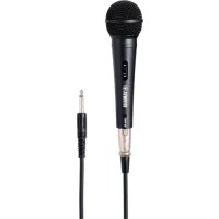
RM-WGS - Microphone YAMAHA - Free user manual and instructions
Find the device manual for free RM-WGS YAMAHA in PDF.

| Product Type | Wireless Microphone System |
| Brand | Yamaha |
| Model | RM-WGS |
| Frequency Range | UHF 620-680 MHz |
| Transmission Type | Digital |
| Operating Range | Up to 100 m (line of sight) |
| Number of Channels | 100 |
| Audio Output | XLR, 1/4" balanced/unbalanced |
| Power Supply (Receiver) | DC 12V, 500 mA |
| Power Supply (Transmitter) | 2x AA alkaline batteries |
| Battery Life | Up to 8 hours |
| Dimensions (Receiver) | 200 x 150 x 44 mm |
| Weight (Receiver) | 450 g |
| Dimensions (Transmitter) | 250 x 50 x 50 mm |
| Weight (Transmitter) | 200 g (with batteries) |
| Included Accessories | Microphone, receiver, AC adapter, user manual |
| Color | Black |
| Material | Metal chassis (receiver), ABS plastic (microphone) |
| Certification | CE, FCC |
| Maintenance | Wipe with dry cloth, store in dry place |
| Reparability | Contact authorized Yamaha service center |
| Safety | Use only supplied power adapter; avoid liquid exposure |
Frequently Asked Questions - RM-WGS YAMAHA
User questions about RM-WGS YAMAHA
0 question about this device. Answer the ones you know or ask your own.
Ask a new question about this device
Download the instructions for your Microphone in PDF format for free! Find your manual RM-WGS - YAMAHA and take your electronic device back in hand. On this page are published all the documents necessary for the use of your device. RM-WGS by YAMAHA.
USER MANUAL RM-WGS YAMAHA
RM Series Wireless Microphone System
Reference Manual
Microphone Access Point
RM-WAP-8
Wireless Microphone
RM-WOM RM-WDR RM-WGL RM-WGS
Microphone Charger
RM-WCH-8
CONTENTS
INTRODUCTION....1
Information....1
SETUP 2
CONTROLS AND CONNECTORS....12
RM-WAP-8....12
RM-WOM RM-WDR 14
RM-WGL RM-WGS 16
RM-WCH-8 17
WEB GUI....19
Structure of RM-WAP Device Manager 19
Functions of RM-WAP Device Manager....21
MAIN SPECIFICATIONS....39
RM-WAP-8....39
RM-WOM RM-WDR RM-WGL RM-WGS 40
RM-WCH-8 42
INTRODUCTION
Thank you for purchasing products of the Yamaha RM series wireless microphone system. This document provides detailed information on the product functions and specifications as well as the Web GUI. For correct and safe use of the products, be sure to first read this manual carefully together with the Owner's Manual (included with each product).
Information
- The illustrations and images shown in this manual are for instructional purposes only.
- The company names and product names in this manual are trademarks or registered trademarks of their respective companies.
• We are continuously improving the software for our products. The latest version can be downloaded from the Yamaha website. - This document is based on the latest specifications at the time of publication. The latest version can be downloaded from the Yamaha website.
- Reproduction of this manual in whole or in part without permission is prohibited.
- In this manual, the microphone access point is referred to as “access point”, the wireless microphone is referred to as “microphone”, and the microphone charger is referred to as “charger”.
SETUP
In order to use the products, setup is required. Set up the products using the Web GUI "RM-WAP Device Manager".
Prepare the following.
- Computer
• LAN cable - PoE powered network switch
- RM-WAP
• RM-WCH (required for using the AUTO SETUP function) - Microphones (RM-WOM, RM-WDR, RM-WGL or RM-WGS)
Starting RM-WAP Device Manager
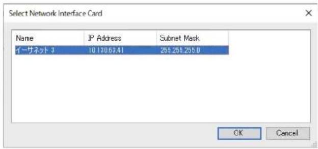
- Download the application "RM Device Finder" from the Yamaha website (U.S.A. and Canada: https://uc.yamaha.com/support/, Other countries: https://download.yamaha.com/), and then start it.
- Using a LAN cable, connect the computer to the network switch where the access point is connected.
- Select a network in the [Select Network Interface Card] window, and then click [OK].
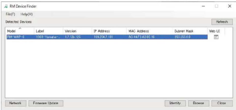
- Double-click this unit in the [Detected Devices] window. Alternatively, select this unit, and then click the [Browse] button.
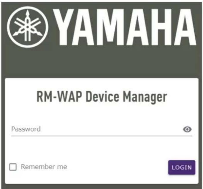
The password settings window of RM-WAP Device Manager appears.
- Specify a password in the password settings window, and then click the [SET PASSWORD] button.
RM-WAP Device Manager
Please set a password
Device Management Account

Device Management User Account Password

Repeat Password

SET PASSWORD
- Type the password into the login window, and then click the [LOGIN] button.
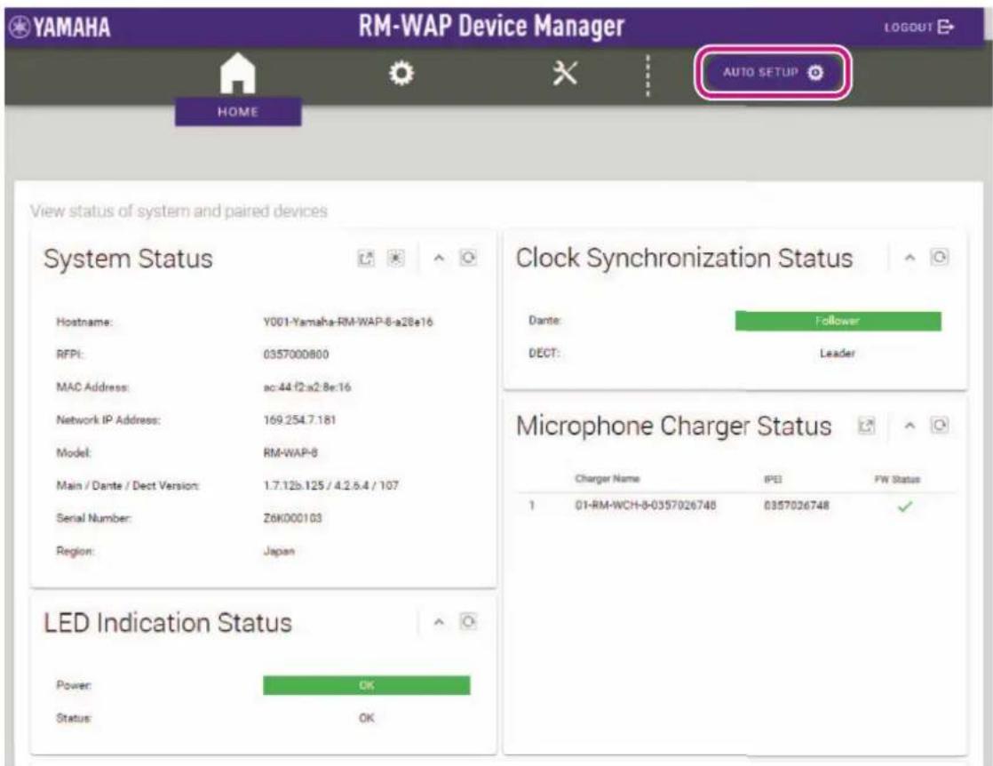
The [HOME] window appears.
SITE SURVEY
Before installing the products, use the SITE SURVEY function in RM-WAP Device Manager to measure the signal in the area.
With the SITE SURVEY function, you can check the number of microphones that can be used in the measured area.
The SITE SURVEY function is available via [TOOLS]→[SITE SURVEY] (Page 33).
IMPORTANT: If radio frequency interference occurs, there may be no sound from the microphones or the microphone connection may be unexpectedly cut. We recommend thoroughly examining the environment before installation.
AUTO SETUP
After products have been installed, their settings can be specified.
With the AUTO SETUP function, product settings can be specified using the wizard.
IMPORTANT: • For details on mounting the access point to the wall or ceiling, read the RM-WAP Owner's Manual.
- RM-WCH is required in order to use the AUTO SETUP function. Even in an environment where the AUTO SETUP function cannot be used, RM-WAP Device Manager can be used to manually specify settings. (Page 19)
1. Click the [AUTO SETUP] button.
The wizard starts up.
2. Follow the wizard's instructions to continue the setup.
[① Site Survey]
Check the contents of the window, and then click the [CONTINUE] button.
The window shows the number of microphones that can be used in the installation environment. It also shows the signal strength in the installation environment and the channel usage status.
![YAMAHA RM-WGS - [① Site Survey] - 1](/content/2026/05/1058579/images/2d65df52efa8d9cbcaba0ebfc2bcccae672d24722737be605cd1a4527bae986b.jpg)
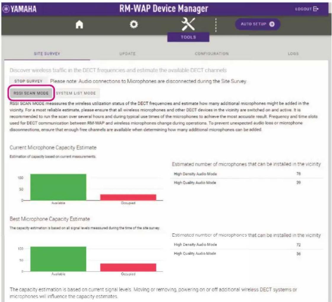
RSSI SCAN MODE measures the wireless utilization status of the DECT frequencies and estimate how many additional microphones might be added in the vicinity. For a most reliable estimate, please ensure that all wireless microphones and other DECT devices in the vicinity are switched on and active. It is recommended to run the scan over several hours and during typical use times of the microphones to achieve the most accurate result. Frequency and time slots used for DECT communication between RM-WAP and wireless microphones change during operations. To prevent unexpected audio loss or microphone disconnections, ensure that enough-free channels are available when determining how many additional microphones can be added.
Estimated number of microphones that can be installed in the vicinity
| High Density Audio Mode | 80 |
| High Quality Audio Mode | 40 |
Estimated number of microphones that can be installed in the vicinity
| High Density Audio Mode | 75 |
| High Quality Audio Mode | 37 |
The capacity estimation is based on current signal levels. Moving or removing, powering on or off additional wireless DECT systems or microphones will influence the capacity estimates
![YAMAHA RM-WGS - [① Site Survey] - 2](/content/2026/05/1058579/images/ba1166132385a5a5cbd531563a57c21455def11bf775b5fc65b6669855c37197.jpg)
heatmap
| Carriers | 1 | 2 | 3 | 4 | 5 | 6 | 7 | 8 | 9 | 10 | 11 | 12 | 13 | 14 | 15 | 16 | 17 | 18 | 19 | 20 | 21 | 22 | 23 | 24 | |---|---|---|---|---|---|---|---|---|---|---|---|---|---|---|---|---|---|---|---|---|---|---|---|---| | 1- | -100 | -100 | -100 | -100 | -100 | -100 | -100 | -100 | -100 | -100 | -100 | -100 | -100 | -100 | -100 | -100 | -100 | -100 | -100 | -100 | -105 | -105 | -105 | -105 | | 2- | -100 | -100 | -100 | -100 | -100 | -100 | -100 | -100 | -100 | -100 | -100 | -100 | -100 | -100 | -100 | -100 | -100 | -100 | -100 | -125 | -125 | -125 | -125 | -125 | | 3- | -100 | -100 | -100 | -100 | -100 | -100 | -100 | -100 | -100 | -100 | -100 | -100 | -100 | -100 | -100 | -100 | -100 | -125 | -125 | -255 | -255 | -255 | -255 | -255 | | 4- | -100 | -100 | -100 | -100 | -100 | -100 | -100 | -100 | -100 | -100 | -100 | -100 | -100 | -100 | -100 | -125 | -125 | -85 | -85 | 355 | 355 | 355 | 355 | 355 | | 5- | -100 | -85 | 35 | 35 | 35 | 35 | 35 | 35 | 35 | 35 | 35 | 35 | 35 | 35 | 35 | 35 | 35 | 35 | 35 | 35 | 35 | 35 | 35 | 35 | | 6- | -85 | 85 | 85 | 85 | 85 | 85 | 85 | 85 | 85 | 85 | 85 | 85 | 85 | 85 | 85 | 85 | 85 | 85 | 85 | 85 | 85 | 85 | 85 | 85 | | ... (final row) ~ all devices in the right column are not available or not activated; any non-synchronized device will occupy two adjacent channels. For maximized DECT usage please enable synchronization on all devices in the vicinity where possible.NOTE:
- You can also click the title of the next window (in this case, [② General Settings]) to display the next window.
- Once the window has been displayed, the circled number in the window title is replaced with clicking a window title where the circled number has been replaced with displays that window again.
Auto Setup Wizard


[② General Settings]
Check the access point settings, and then click the [CONTINUE] button.
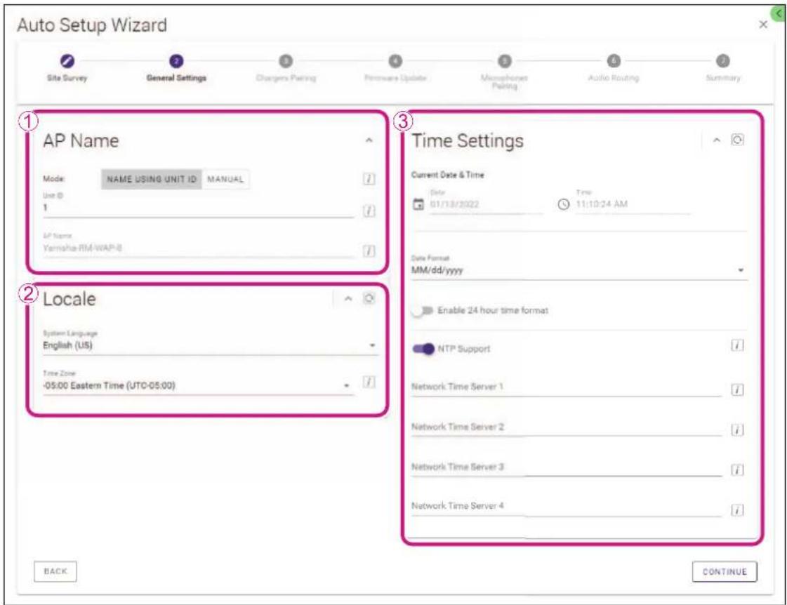
NOTE: The access point settings can be changed if necessary.
①[AP Name]
Allows you to select whether to specify the name of the access point automatically or manually.
②[Locale]
Allows you to specify the time zone.
③[Time Settings]
- Allows you to specify the date and time.
- Allows you to select whether to use NTP.
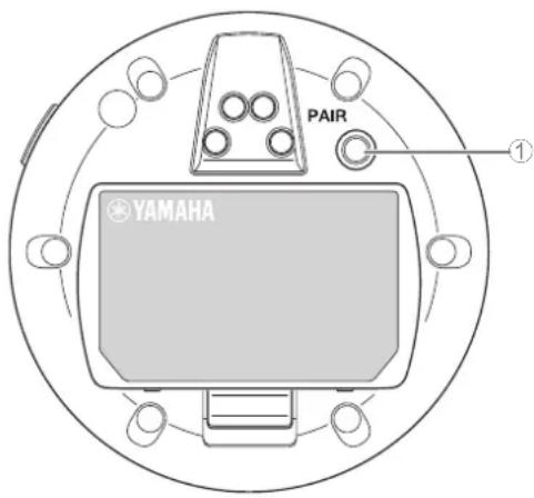
[③ Chargers Pairing]
① Insert the charger power plug into an electrical outlet.
The charger starts up.
② Long-press the PAIR button (on the bottom panel of the charger) for at least two seconds.
The access point and charger are paired. When pairing is finished, the charger name appears in the window.
NOTE: Pairing means that the products register each other with the information required for a DECT connection. The access point and charger are paired, and a DECT connection is established at the same time.
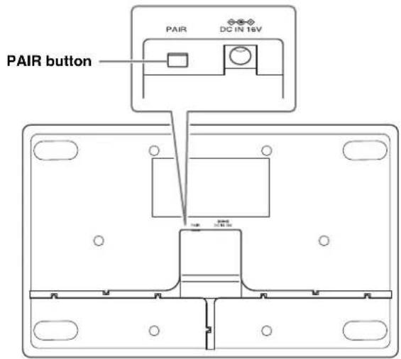
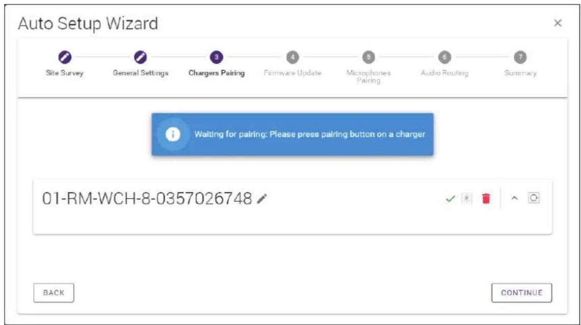
③Click the [CONTINUE] button.
[4 Firmware Update]
① If 📊 appears to the left of the charger name, click the [UPDATE ALL] button.
The charger firmware is updated. When the update is finished, changes to .
NOTE: If appeared from the beginning, step 1 does not need to be performed.
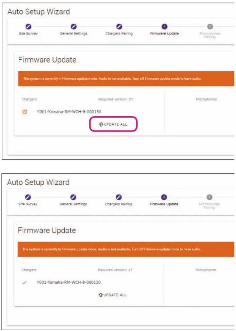
②Place the microphone(s) on the charger.
The microphone firmware is updated. During the update, the Mic indicators (on the top panel of the microphone) flashes white quickly. When the update is finished, the indicators go off.
IMPORTANT: Do not remove the microphone(s) from the charger until setup is finished.
NOTE: The microphones are updated one at a time.
③Click the [CONTINUE] button.
[5] Microphones Pairing]
The name(s) of the microphone(s) appear faintly in the window.
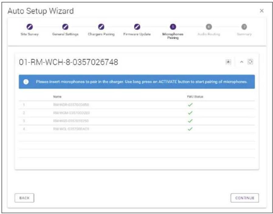
① Long-press the ACTIVATE button (on the top panel of the charger) for at least two seconds.
The access point and microphone(s) are paired. When pairing is finished, the name(s) of the microphone(s) change from appearing faintly to appearing in black.
NOTE: All microphones placed on the charger can be paired with a single long press.
②Click the [CONTINUE] button.
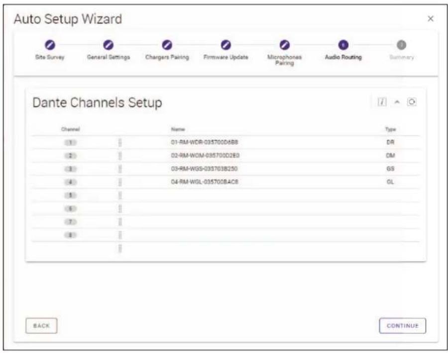
[6 Audio Routing]
Check the Dante channel to which each microphone is assigned, and then click the [CONTINUE] button.
NOTE: You can change the channel assignment by dragging the microphone name to the row of the desired Dante channel.
[7 Summary]
Check the microphone settings, and then click the [FINISH] button.
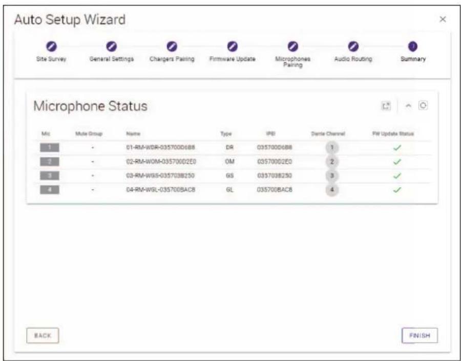
This completes the setup. When a microphone is removed from the charger, a DECT connection between the access point and microphone will be established.
[Front panel]
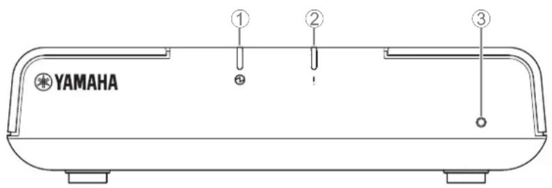
① Power indicator
| Condition Power indicator Unit status | |
| LAN cable plugged into Dante/PoE port Lit green Operating | |
| - Flashes red quickly System error occurring |
② Status indicator
| Condition Status indicator Unit status | ||
| Making DECT connection Lit blue DECT connection has been established | ||
| Pairing using Web GUI Flashes blue quickly Waiting for pairing/Pairing | ||
| Pairing using Web GUI | (After flashing blue quickly)Flashes blue twice | Paired successfully |
| Pairing using Web GUI | (After flashing blue quickly)Flashes red twice | Pairing failed |
| Identify icon in Web GUI clicked | Flashes white | Responding (to Identify function) |
| Updating firmware | Flashes white quickly | Firmware being updated |
| Updating firmware | (After flashing white quickly)Flashes white twice | Firmware updated successfully |
| Updating firmware | (After flashing white quickly)Flashes red twice | Firmware update failed |
| - | Flashes red | Transmission error occurring |
| - Flashes red quickly System error occurring | ||
③Reset button
| Condition Status indicator Unit status | ||
| Reset button long-pressed for 4 seconds to less than 8 seconds, then released | Flashes blue twice per second (during long-pressing/resetting) | Network-related settingsWaiting for resetting/Resetting(Automatically restarts after reset) |
| Reset button long-pressed for 8 seconds to less than 12 seconds, then released | Flashes blue three times per second (during long-pressing/resetting) | All settingsWaiting for resetting/Resetting(Automatically restarts after reset) |
NOTE: Use a fine-tipped object to press the Reset button.
[Bottom panel]
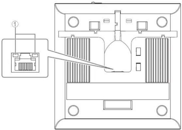
①Network port indicators (Dante/PoE port)
| Network port indicator Unit status | |
| Left indicator lit green Link up | |
| Left indicator flashes green Transferring data | |
| Left indicator unlit Link down | |
| Right indicator lit green Operating on | word clock of peripheral device (leader) |
| Right indicator flashes green Acting as | word-clock leader |
| Right indicator flashes orange Word clock | unlocked |
NOTICE:
- When disconnecting the LAN cable from the Dante/PoE port, wait at least five seconds before reconnecting the cable. Otherwise, damage or malfunctions may result.
-
With a Dante network, do not use the EEE function* of the network switch. Although mutual power consumption settings are automatically adjusted between switches that support the EEE function, some switches do not perform that properly. As a result, the switch's EEE function may be enabled inappropriately in the Dante network, possibly degrading clock synchronization performance and interrupting audio. Therefore, please note the following.
-
When using managed switches, turn off the EEE function on all ports used for Dante. Do not use a switch that does not allow the EEE function to be turned off.
- When using unmanaged switches, do not use switches that support the EEE function. In such switches, the EEE function cannot be turned off.
* EEE (Energy-Efficient Ethernet) function: Technology that reduces the power consumption of Ethernet devices during periods of low network traffic; also known as Green Ethernet or IEEE802.3az.
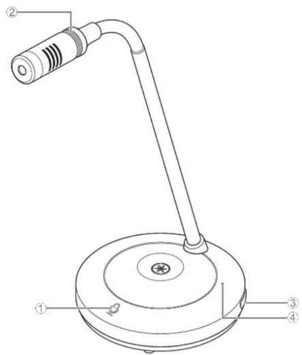
[Top panel/side panel]
RM-WOM
RM-WDR
① Mic buttons/indicators
| Condition Mic indicator Unit status | ||
| Mic button touched Lit green Microphone on | ||
| Mic button touched | Lit red(Flashes every 2 seconds) | Microphone off |
| Identify icon in Web GUI clicked Flashes white Responding (to Identify function) | ||
| Updating firmware Flashes white quickly Firmware being updated | ||
| Updating firmware | (After flashing white quickly)Flashes white twice | Firmware updated successfully |
| Updating firmware | (After flashing white quickly)Flashes red twice | Firmware update failed |
| - Flashes red Transmission error occurring | ||
| - Flashes red quickly System error occurring | ||
| - Flashes red slowly Out of range for DECT connection | ||
② Battery button
③Battery indicator
| Condition Battery indicator | Unit status | |
| Charging the unit Lit green | Charging (available operating time of 15 hours or more) | |
| Charging the unit Lit orange | Charging (available operating time of 3 hours to less than 15 hours) | |
| Charging the unit Lit red | Charging (available operating time of less than 3 hours) | |
| Charging the unit Unlit Charging finished | ||
| Battery button pressed Lit green for two seconds Remaining operating time of 15 hours or more | ||
| Battery button pressed | Lit orange for two seconds | Remaining operating time of 3 hours to less than 15 hours |
| Battery button pressed | Lit red for two seconds | Remaining operating time of less than 3 hours |
| (Continuing to use the unit without charging) | Flashes red | Remaining operating time of less than 1 hour |
| Battery button long-pressed for 2 to 3 seconds | Flashes orange slowly | Enters standby mode |
IMPORTANT: The microphone is pre-installed with an RM-WBT battery. In order to maintain battery capacity, charge the microphone (battery) once every six months.
NOTE: • Power consumption can be reduced by putting the microphone in standby mode.
- Putting the microphone in standby mode cuts the DECT connection with the access point. When the standby mode is exited (by long-pressing the Battery button again for 2 to 3 seconds), the connection is re-established.
[Bottom panel]
①PAIR button
| Condition | Mic indicator | Unit status |
| PAIR button long-pressed for at least 2 seconds | Flashes blue quickly | Waiting for pairing/Pairing |
| PAIR button long-pressed for at least 2 seconds | (After flashing blue quickly) Flashes blue twice | Paired successfully |
| PAIR button long-pressed for at least 2 seconds | (After flashing blue quickly) Flashes red twice | Pairing failed |
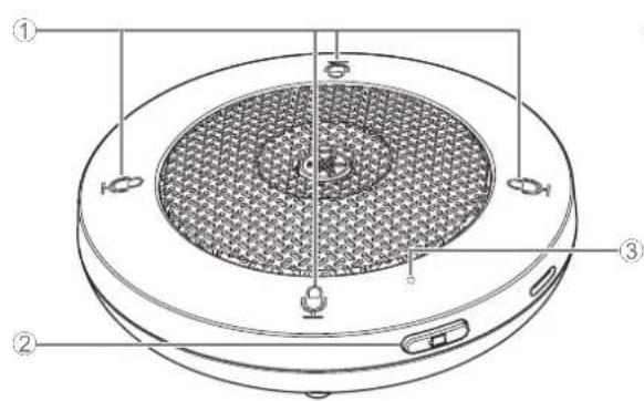
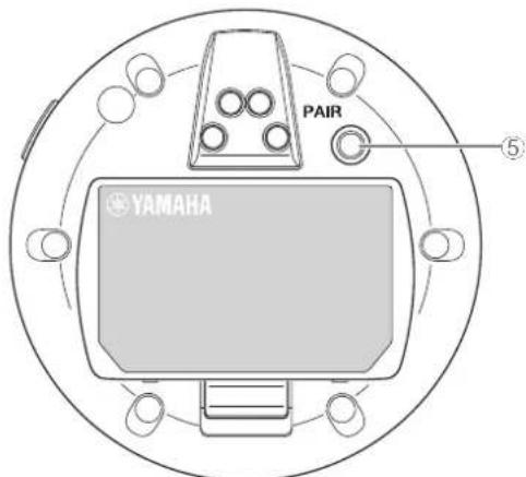
[Top panel/side panel]
RM-WGL RM-WGS
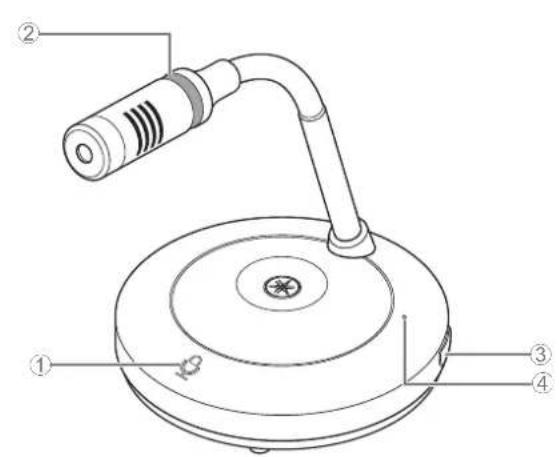
① Mic buttons/indicators
| Condition Mic indicator Unit status | ||
| In Toggle mode:Mic button touched continuously | Lit green Microphone | on |
| In Toggle mode: Mic button released Lit red | Microphone off | |
| In Push to talk mode:Mic button touched continuously | Lit green Microphone | on while the button is touched |
| In Push to talk mode: Mic button released | Lit red(Flashes every 2 seconds) | Microphone off |
NOTE: Push to talk is a communication method that allows you to talk only while a button is pressed. Multiple devices cannot be used to talk at the same time. For details on switching to Toggle mode or Push to talk mode, refer to page 26.
All other Mic button/indicator functions are the same as described for RM-WOM and RM-WDR.
②Ring indicator
Flashes together with the Mic indicators.
③ Battery button
④Battery indicator
Functions in the same way as the Battery button/indicator of the RM-WOM and RM-WDR.
[Bottom panel]
⑤PAIR button
Functions in the same way as the PAIR button of the RM-WOM and RM-WDR.
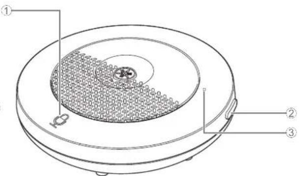
RM-WCH-8
[Top panel]
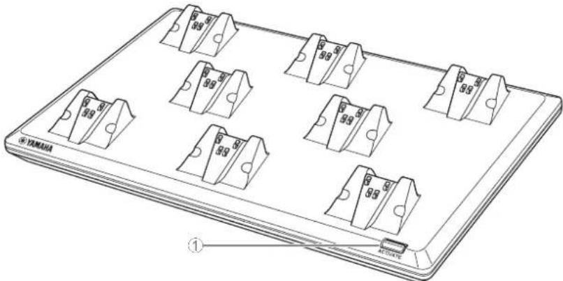
①ACTIVATE button/indicator
| Condition ACTIVATE indicator Unit status | ||
| Power plug inserted into electrical outlet Lit green Operating | ||
| ACTIVATE button long-pressed for at least 2 seconds | Flashes blue quickly | Waiting for pairing/Pairing of access point and microphone(s) |
| ACTIVATE button long-pressed for at least 2 seconds | (After flashing blue quickly) Flashes blue twice | Access point and microphone(s) paired successfully |
| ACTIVATE button long-pressed for at least 2 seconds | (After flashing blue quickly) Flashes red twice | Pairing of access point and microphone(s) failed |
| Identify icon in Web GUI clicked Flashes white Responding (to Identify function) | ||
| Updating firmware Flashes white quickly Firmware being updated | ||
| Updating firmware | (After flashing white quickly) Flashes white twice | Firmware updated successfully |
| Updating firmware | (After flashing white quickly) Flashes red twice | Firmware update failed |
| – Flashes red Transmission error occurring | ||
| – Flashes red quickly System error occurring | ||
[Bottom panel]
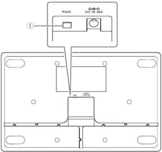
①PAIR button
| Condition ACTIVATE indicator | Unit status | |
| PAIR button long-pressed for at least 2 seconds | Flashes blue quickly | Waiting for pairing/Pairing |
| PAIR button long-pressed for at least 2 seconds | (After flashing blue quickly) Flashes blue twice | Paired successfully |
| PAIR button long-pressed for at least 2 seconds | (After flashing blue quickly) Flashes red twice | Pairing failed |
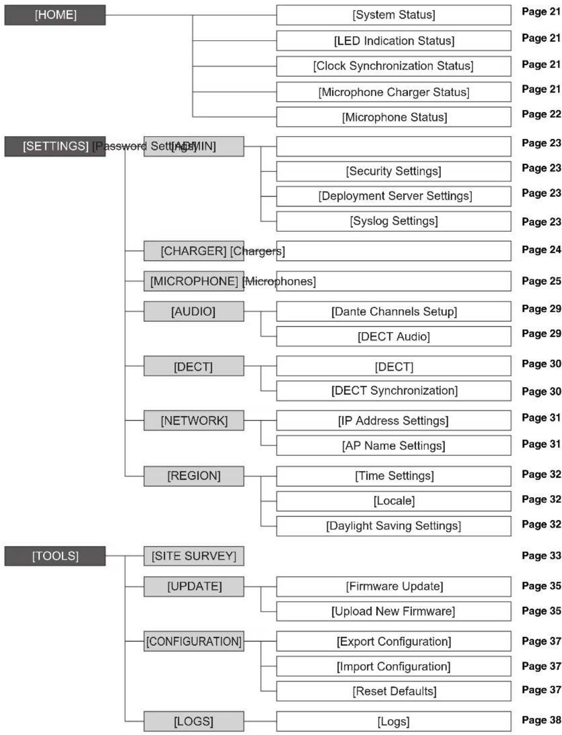
Use the Web GUI "RM-WAP Device Manager" to check/change the settings of the units.
Structure of RM-WAP Device Manager
Refer to the page listed to the right for details on each item available in the various windows.
flowchart
graph TD
    A["HOME"] --> B["Password Settings"]
    A --> C["ADMIN"]
    A --> D["Charger"]
    A --> E["AUDIO"]
    A --> F["DECT"]
    A --> G["NETWORK"]
    A --> H["REGION"]
    A --> I["SITE SURVEY"]
    A --> J["UPDATE"]
    A --> K["CONFIGURATION"]
    A --> L["LOGS"]

    B --> M["System Status"]
    B --> N["LED Indication Status"]
    B --> O["Clock Synchronization Status"]
    B --> P["Microphone Charger Status"]
    B --> Q["Microphone Status"]

    C --> R["Security Settings"]
    C --> S["Deployment Server Settings"]
    C --> T["Syslog Settings"]

    D --> U["Charger"]
    D --> V["Microphones"]
    D --> W["Dante Channels Setup"]
    D --> X["DECT Audio"]

    E --> Y["DECT"]
    E --> Z["IP Address Settings"]
    E --> AA["AP Name Settings"]

    F --> AB["Time Settings"]
    F --> AC["Locale"]
    F --> AD["Daylight Saving Settings"]

    G --> AE["Firmware Update"]
    G --> AF["Upload New Firmware"]

    H --> AG["Configuration"]
    H --> AH["Reset Defaults"]

    I --> AI["Logs"]

    style A fill:#f9f,stroke:#333
    style B fill:#ccf,stroke:#333
    style C fill:#cfc,stroke:#333
    style D fill:#fcc,stroke:#333
    style E fill:#cff,stroke:#333
    style F fill:#ffc,stroke:#333
    style G fill:#fcc,stroke:#333
    style H fill:#cff,stroke:#333
    style I fill:#fcc,stroke:#333
The following icons buttons are used in RM-WAP Device Manager.
i (Information icon): Move the pointer over this icon to see more information about the item.
(Reload button): Click to update the window contents.
(Identify button): Click to cause the indicator of the corresponding device to flash.
(Link button): Click to go to another window for the item.
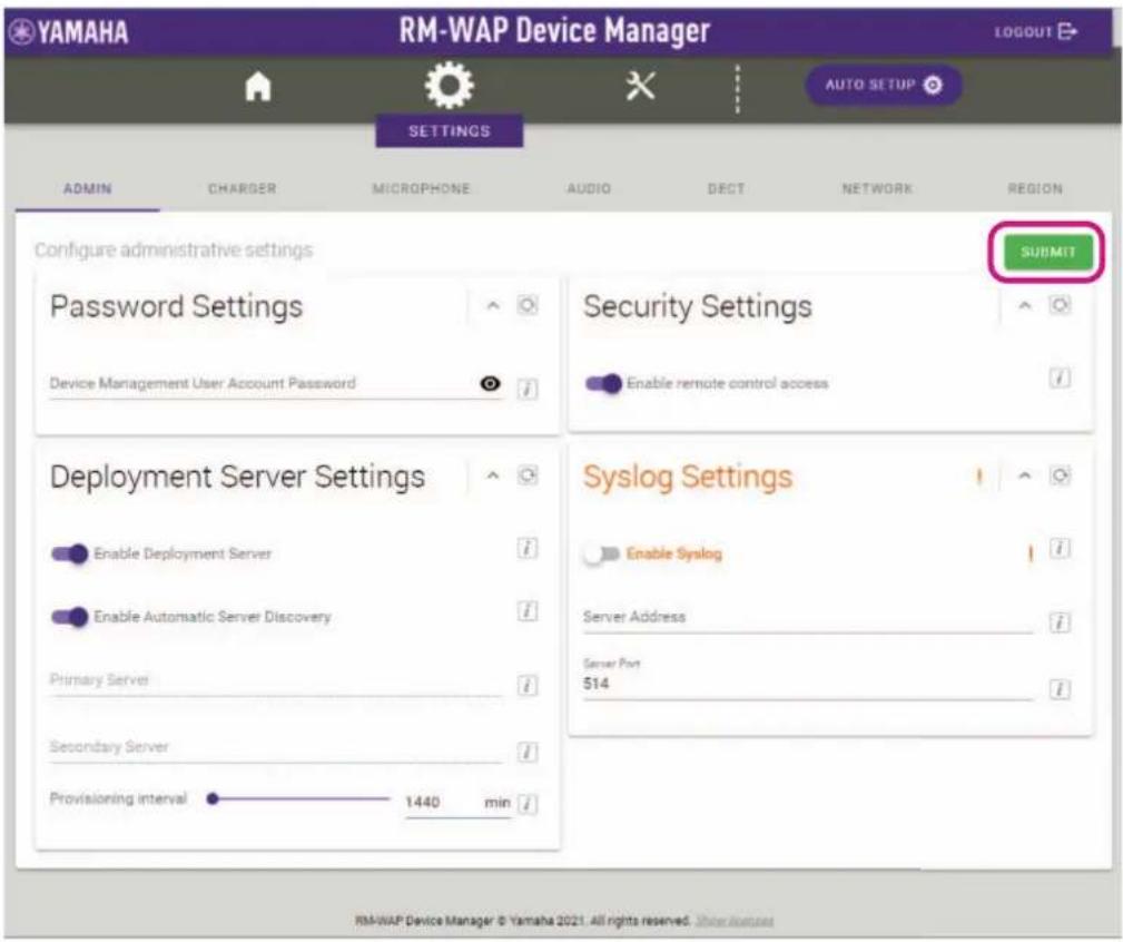
IMPORTANT: Be sure to click the [SUBMIT] button after changing settings in RM-WAP Device Manager. The [SUBMIT] button always appears in the upper-right corner of the window.
[HOME]
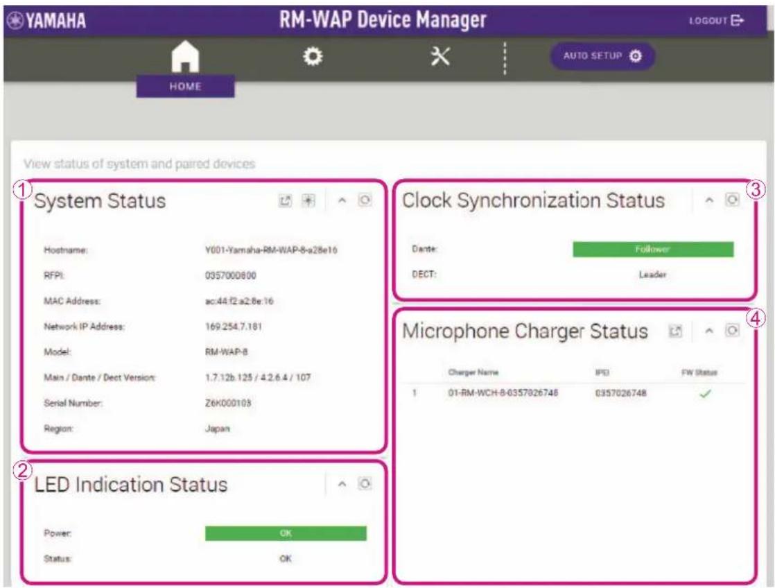
①[System Status]
Allows you to check basic information about the access point.
②[LED Indication Status]
Allows you to check the status of the Indicator of the access point.
③[Clock Synchronization Status]
- Allows you to check the status of the Dante word clock.
"Leader" or "Follower" appears. If there is an abnormality in the word clock, this appears in orange. - Allows you to check the status of the DECT frame synchronization.
"Leader" or "Follower" appears. When multiple access points are set up in the same group, one will be the "Leader" and the others will be "Follower". The access point group settings can be specified via [SETTINGS]→[DECT]→[DECT Synchronization].
④[Microphone Charger Status]
Allows you to check the name of the charger.
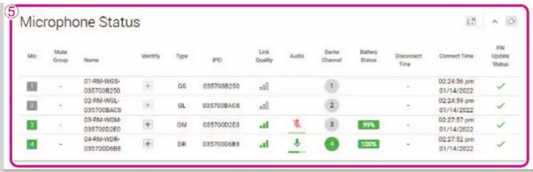
⑤[Microphone Status]
Allows you to check the statuses of the microphones.
- [IPEI]:
Identification number of the DECT module
- [Link Quality]:
Shows the strength of the radio wave as one of four levels indicated by the number of bars.
- [Audio]:
Click the icon to turn on/off the microphone.
- [Battery Status]:
Shows the battery charge as a percentage.
Indicates the remaining charge of the battery by a color.
Red: 3% to 10%, 1 to 3 hours
Yellow: 10% to 50%, 3 to 15 hours
Green: 50% or more, 15 hours or more
- [Disconnect Time]:
Shows the time at which the microphone and access point were disconnected.
- [Connect Time]:
Shows the time at which the microphone and access point were connected.
- [FW Update Status]:
Shows the firmware update status.
If the firmware must be updated, appears.
Update the firmware via [TOOLS]→[UPDATE]→[Firmware Update].
[SETTINGS]
[ADMIN]
①[Password Settings]
Allows you to check/change the password for logging in to RM-WAP Device Manager.
②[Security Settings]
Allows you to select whether to enable remote control. For details on remote control, refer to the RM Series Remote Control Protocol Specifications.
IMPORTANT: Remote control must be enabled for the access point to link to the RM-CR signal processor.
③[Deployment Server Settings]
By using a deployment server, the device configuration file can be automatically acquired and applied to the device.
- [Enable Deployment Server]:
Allows you to select whether to use a deployment server. - [Enable Automatic Server Discovery]:
Allows you to select whether to use the automatic discovery feature of the deployment server. - [Primary Server], [Secondary Server]:
Specify the IP address of the deployment server when [Enable Automatic Server Discovery] is off. - [Provisioning Interval]:
Allows you specify the deployment server provisioning interval.
④[Syslog Settings]
Allows you to select whether to use a syslog server.
[CHARGER]
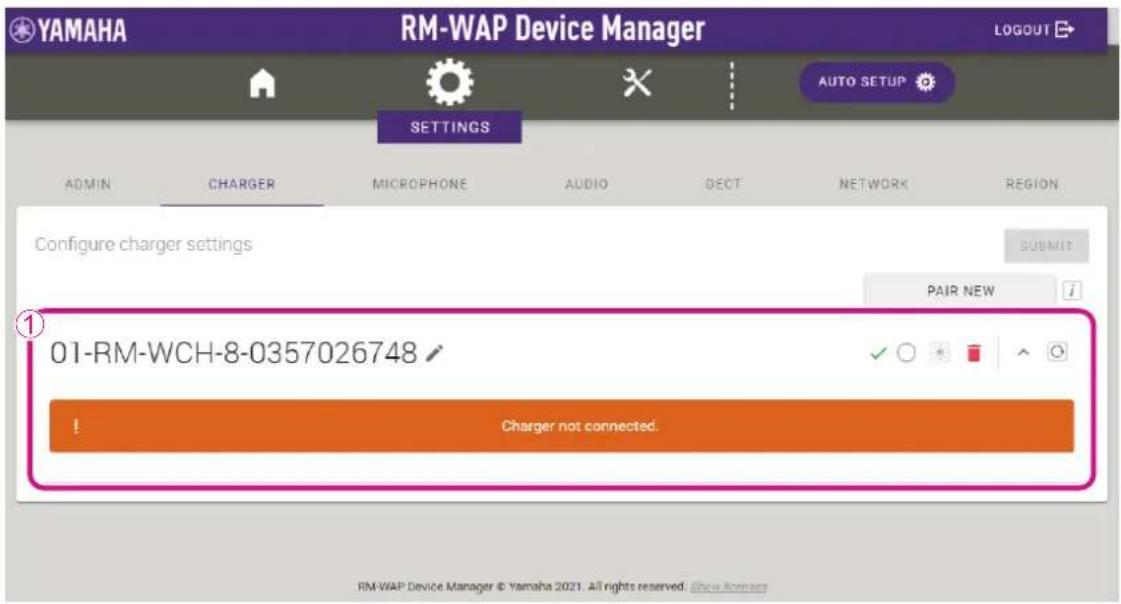
①[Chargers]
- Allows you to pair the access point and charger. Click the [PAIR NEW] button to put the access point in pairing standby mode, and then long-press the PAIR button (on the bottom panel of the charger) for at least two seconds. When pairing is finished, the charger name appears in the window.
- Allows you to check/change the name of the charger.
- Allows you to cancel pairing by clicking (trash can).
[MICROPHONE]
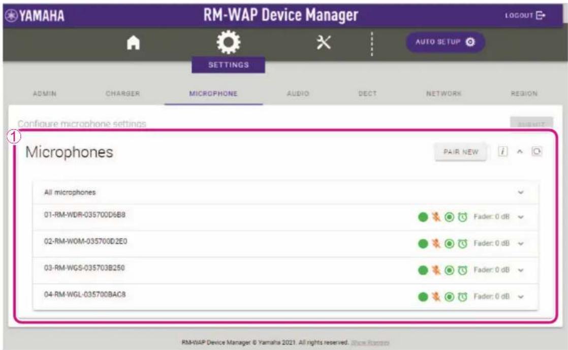
①[Microphones]
- Allows you to pair the access point and microphones. Click the [PAIR NEW] button in the window to put the access point in pairing standby mode, and then long-press the PAIR button (on the bottom panel of the microphone) for at least two seconds. When pairing is finished, the microphone name appears in the window.
• Shows the microphone settings as icons.
- [Start Mode]:
: Starts up in Start Up mode.
: Starts up in Standby mode.
- [Start Mute Mode]:
: Starts up with the microphone turned off.
: Starts up with the microphone turned on.
- [Mic Button Behavior]:
: The Mic button operates in Toggle mode.
: The Mic button operates in Push to talk mode.
○ : The Mic button is deactivated.
- [Alarm when out of area]:
: The alarm when out of range for DECT connection is on.
: The alarm when out of range for DECT connection is off.
- [Fader Level]:
Shows the microphone fader level. The setting range is between -128 dB and +12 dB.
- Allows you to expand the settings window by clicking a row containing the name of a microphone.
- Allows you to check/change microphone settings.
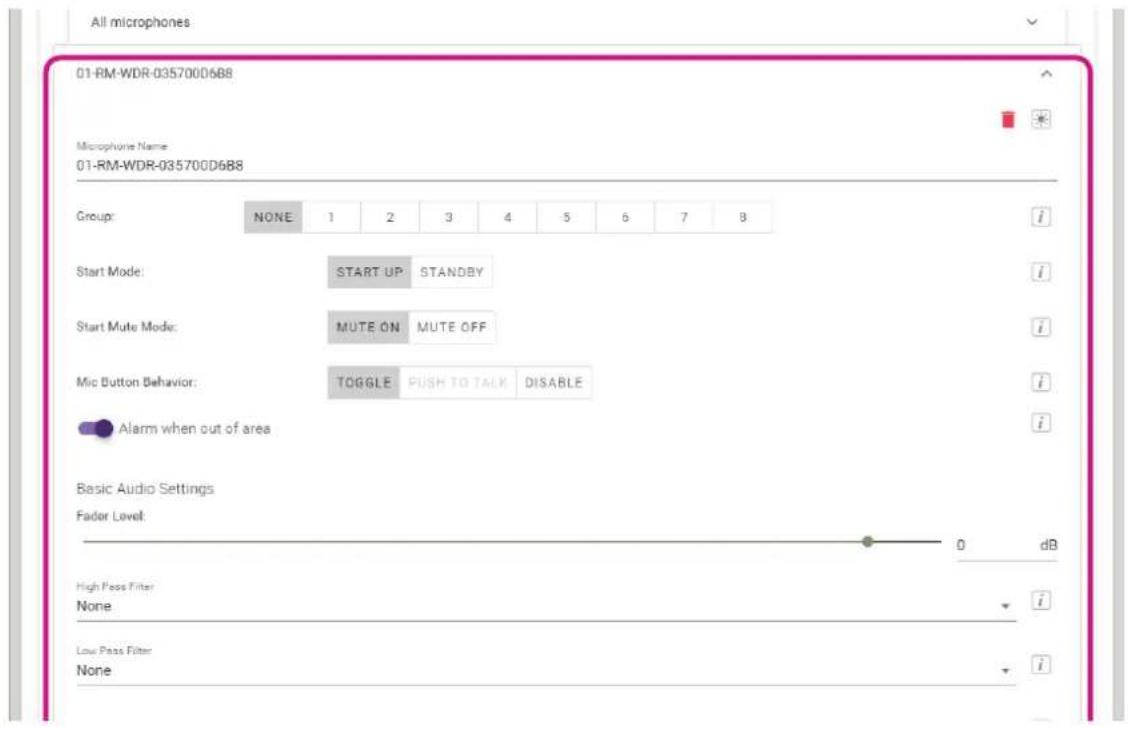
- [Michrophone Name]:
Allows you to check/change the name of the microphone.
- [Group]:
Allows you to group the microphones. Grouping microphones synchronizes them when turning one on/off.
- [Start Mode]:
Allows you to select whether the microphone enters Standby mode when it is started up.
- [Start Mute Mode]:
Allows you to select whether the mic is on or off when the microphone is started up.
- [Mic Button Behavior]:
Allows you to set the operation of the Mic button to one of the following.
- [TOGGLE]:
Turn on/off the microphone by touching the Mic button.
- [PUSH TO TALK]:
The microphone is on while the Mic button is touched. Multiple devices cannot be used to talk at the same time.
- [DISABLE]:
The Mic button is deactivated.
- [Alarm when out of area]:
Allows you to select whether the Mic indicator flashes to indicate that the microphone is out of range for a DECT connection.
- [Fader Level]:
Allows you specify the microphone fader level. The setting range is between -128 dB and +12 dB.
- [High Pass Filter]:
Allows you to select the High Pass filter setting. Select one of the following: NONE, 110 Hz, 140 Hz, 175 Hz, 225 Hz.
- [Low Pass Filter]:
Allows you to select the Low Pass filter setting. Select one of the following: NONE, 4 kHz, 8 kHz, 12 kHz.
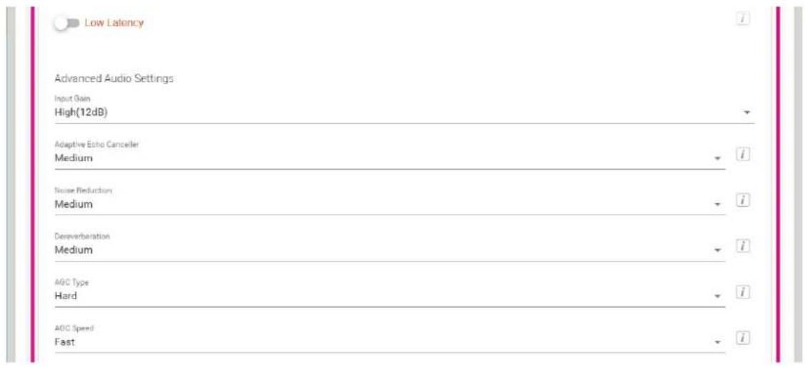
- [Low Latency]
When Low Latency is on, processing of the following Advanced Audio Settings can be bypassed to reduce audio delay. Input Gain, Adaptive Echo Canceller, Noise Reduction, Dereverberation, AGC and PEQ When used in combination with RM-CR, turn off Low Latency.
- [Input Gain]
Allows you to select the microphone input gain.
With RM-WOM, select one of the following: OFF (0 dB), LOW (3 dB), MEDIUM (6 dB), HIGH (9 dB).
With RM-WDR, select one of the following: OFF (0 dB), LOW (4 dB), MEDIUM (8 dB), HIGH (12 dB).
With RM-WGS, select one of the following: OFF (0 dB), LOW (6 dB), MEDIUM (12 dB), HIGH (18 dB).
With RM-WGL, select one of the following: OFF (0 dB), LOW (6 dB), MEDIUM (12 dB), HIGH (18 dB).
- [Adaptive Echo Canceller]
Allows you to suppress echo generation. Select one of the following: OFF, GENTLE, MEDIUM, STRONG.
- [Noise Reduction]
Allows you to suppress ambient noise from the mix. Select one of the following: OFF, GENTLE, MEDIUM, STRONG.
- [Dereverberation]
Allows you to suppress reverberation. Select one of the following: OFF, GENTLE, MEDIUM, STRONG.
- [AGC Type]
AGC (Auto Gain Control) automatically adjusts the volume of the microphone. For the AGC type, select one of the following: OFF, SOFT, HARD.
- [AGC Speed]
For the AGC speed, select one of the following: OFF, SLOW, FAST.
![YAMAHA RM-WGS - - [AGC Speed] - 1](/content/2026/05/1058579/images/b74011286905c487ec62737b3cfe051b7987f174c58802cb4ae6dfb1290f1f01.jpg)
line
| Band | Type | Value | |------|------|-------| | A | PEQ | 0 | | B | PEQ | 0 | | C | PEQ | 0 | | D | PEQ | 0 | | E | PEQ | 0 | | F | PEQ | 0 | | Q | PEQ | 0.7 | | Frequency | PEQ | 31.5 | | Gain | PEQ | 0 | | Bypass | PEQ | 0 |- [Enable PEQ]
Allows you to select whether to enable PEQ (Parametric EQ). This is effective when used in combination with a processor other than RM-CR.
- [Band], [Type], [Q], [Freq.], [Gain], [Bypass]
Allows you to specify PEQ settings for each of the six bands.
For [Type] under "Band A" or "Band F", select one of the following: PEQ, L.SHELF-6dB/Oct, L.SHELF-12dB/Oct, H.SHELF-6dB/Oct, H.SHELF-12dB/Oct, HPF, LPF.
- Allows you to cancel pairing by clicking (trash can).
[AUDIO]
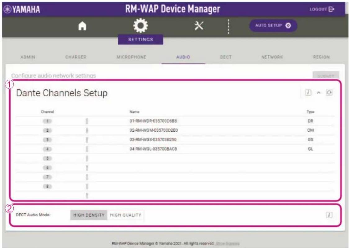
①[Dante Channels Setup]
- Allows you to check the Dante channel assigned to each microphone.
- Allows you to change the channel assignment by dragging the microphone name to the row of the desired Dante channel.
②[DECT Audio]
Allows you to set the access point to High Density mode or High Quality mode. High Quality mode has better audio quality than High Density mode, but the maximum number of microphones that can be used may be limited.
[DECT]
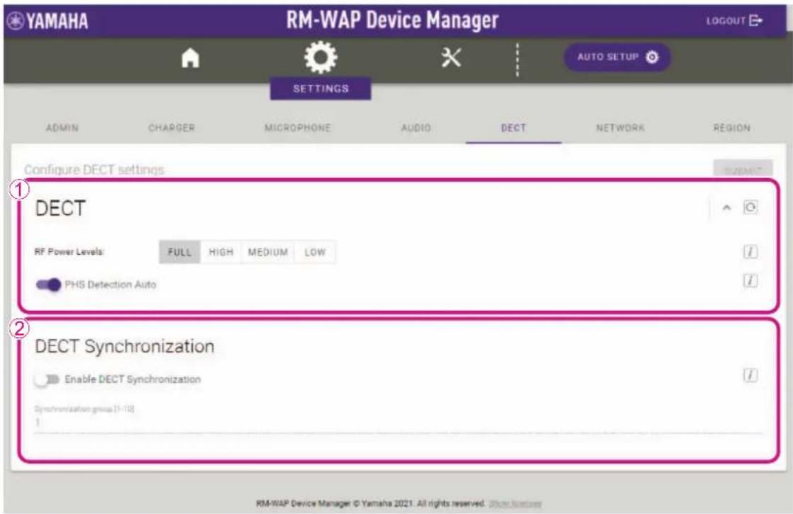
①[DECT]
- Allows you to select the signal strength.
②[DECT Synchronization]
Allows you to select whether to synchronize the DECT frame across multiple access points. When multiple access points are used, turn on [Enable DECT Synchronization], and then put all devices to be synchronized into the same group under [Synchronization group].
[NETWORK]
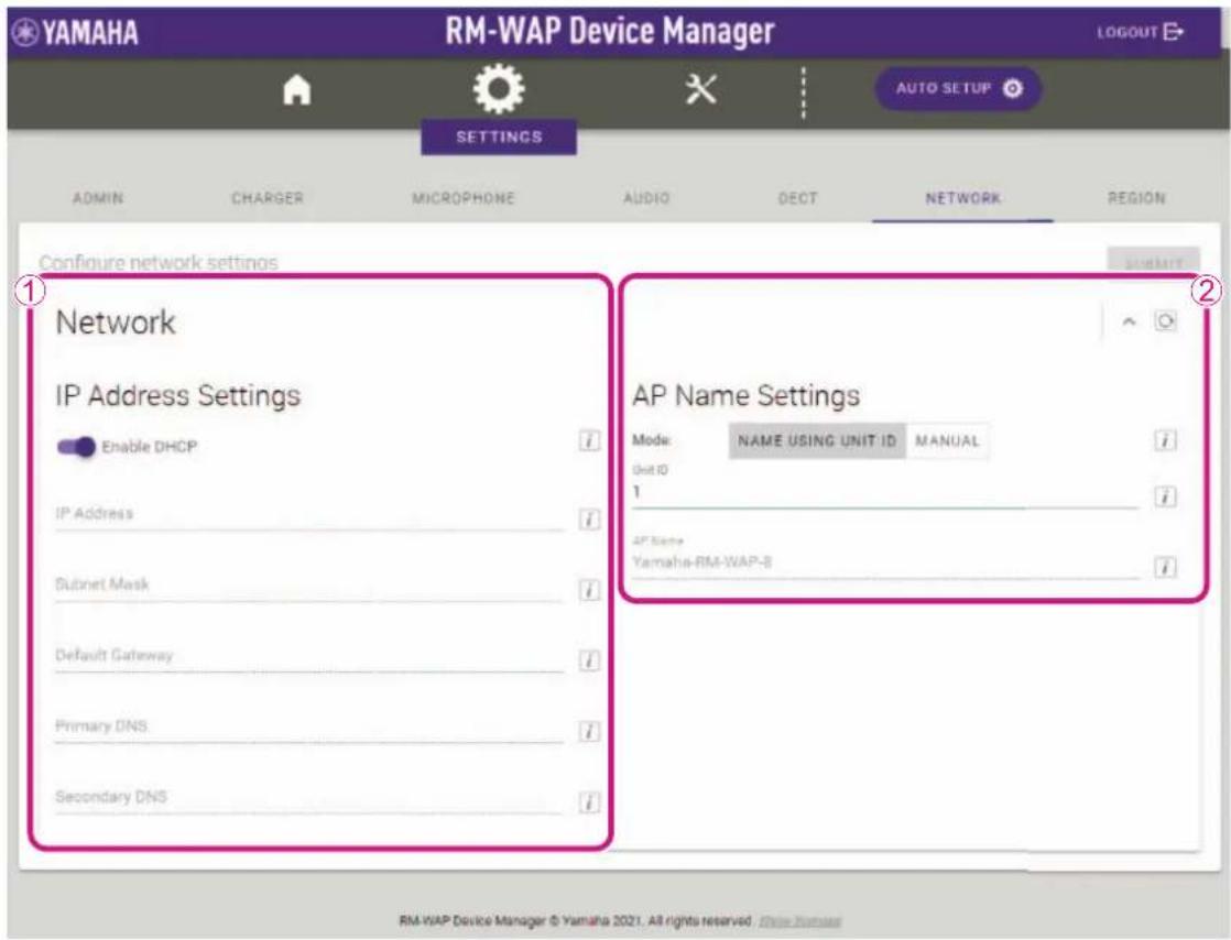
①[IP Address Settings]
Allows you to select whether to use DHCP. When set to use DHCP, the IP address is specified in Auto IP mode if there is no DHCP server.
If settings have been incorrectly specified, press the Reset button on the front of the RM-WAP to reset the network-related settings.
②[AP Name Settings]
Allows you to select whether to specify the name of the access point automatically or manually. For [UNIT ID], enter single-byte hexadecimal characters.
[REGION]
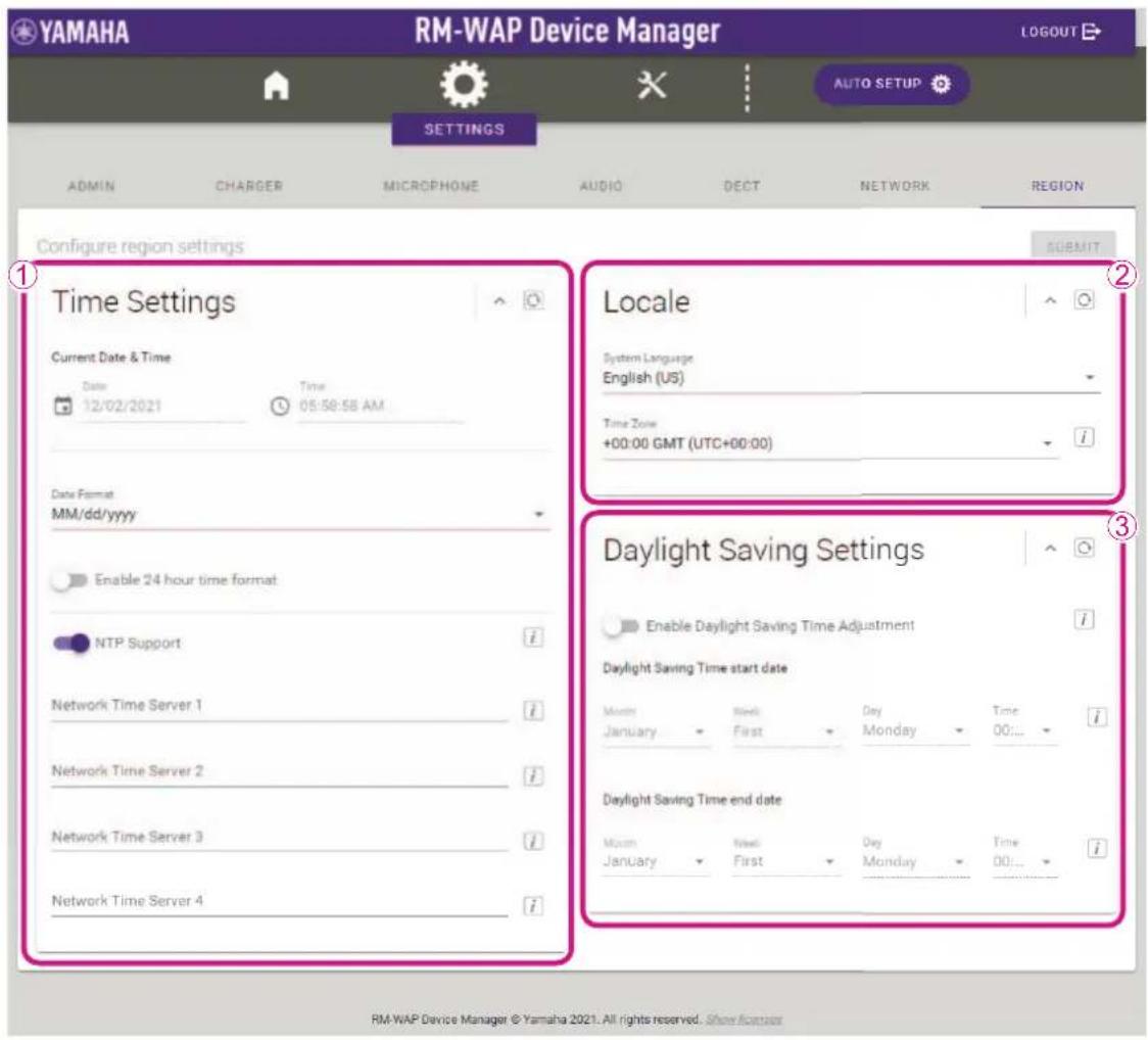
①[Time Settings]
- Allows you to specify the date and time.
- Allows you to select whether to use NTP.
②[Locale]
Allows you to specify the time zone.
③[Daylight Saving Settings]
Allows you to select whether to use daylight saving time with the access point.
[TOOLS]
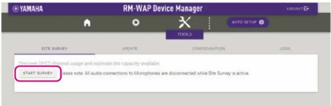
[SITE SURVEY]
- Allows the access point to measure the signal strength in the installation environment and the channel usage status by clicking the [START SURVEY] button.
IMPORTANT: If radio frequency interference occurs, there may be no sound from the microphones or the microphone connection may be unexpectedly cut. We recommend thoroughly examining the environment before installation.
- Allows you to check the measurement results and the number of microphones that can be used in the installation environment, by clicking the [RSSI SCAN MODE] button. For highly accurate measurements, make sure that all nearby wireless microphones and other DECT devices are operational. In addition, it is recommended to measure for several hours under typical usage conditions in order to obtain accurate results. The values beside "High Density Audio Mode" and "High Quality Audio Mode" refer to the maximum number of microphones that can be used in each mode.
Microphone Channel usage
This figure shows the number of available and occupied microphone channels since start of the survey.
![YAMAHA RM-WGS - [SITE SURVEY] - 3](/content/2026/05/1058579/images/934429194271a14052610e49ca016c28a90d8800e24abca3f7498b27c390b53a.jpg)
area
| Date | Occupied | Available | | ---------- | -------- | --------- | | Dec 2, 2021| 120 | 120 |DECT Heatmap
This heatmap shows the received signal strength for each DECT channel. Any channel with a signal strength above -62 dBm is deemed to be currently used by another device for DECT communication. If DECT synchronization is not available or not activated, any non-synchronized DECT device will occupy two adjacent channels. For maximized DECT usage please enable synchronization on all devices in the vicinity where possible.
![YAMAHA RM-WGS - [SITE SURVEY] - 4](/content/2026/05/1058579/images/c2e5c5678f94f8db5d797d8613c715d5247f7f8e817bfcc6c7d4b5b6e3df4438.jpg)
RM-WAP Device Manager © Yamaha 2021. All rights reserved.
- Allows you to check for DECT masters in the installation environment as well as their signal strength by clicking the [SYSTEM LIST MODE] button.

Discover wireless traffic in the DECT frequencies and estimate the available DECT channels
STOP SURVEY Please note: Audio connections to Microphones are disconnected during the Site Survey.
RSSI SCAN MODE SYSTEM LIST MODE
SYSTEM LIST MODE allows to search and find other RM-WAPs and neighboring DECT base stations. Devices will be listed with their RFPI (Radio Fixed Part Identity) and the RSSI (Radio Signal Strength Indicator). Devices with a signal strength of -62 dBm or higher might interfere with the DECT communication of the RM-WAP that is runnign the scan. Interference might lead to unexpected audio loss or microphone disconnections. It is recommended to enable DECT synchronization to synchronize the DECT clock between different WAPs and adjust RF power levels to prevent signal interferences. Please note that RM wireless microphone and other DECT mobile devices, know as Portable Parts, cannot be found in this mode.
| RFFI | RSSI |
| 035700CEC0 | -50 |
| 035703F600 | -54 |
| 035700D808 | -58 |
| 0357049EF8 | -52 |
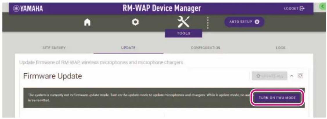
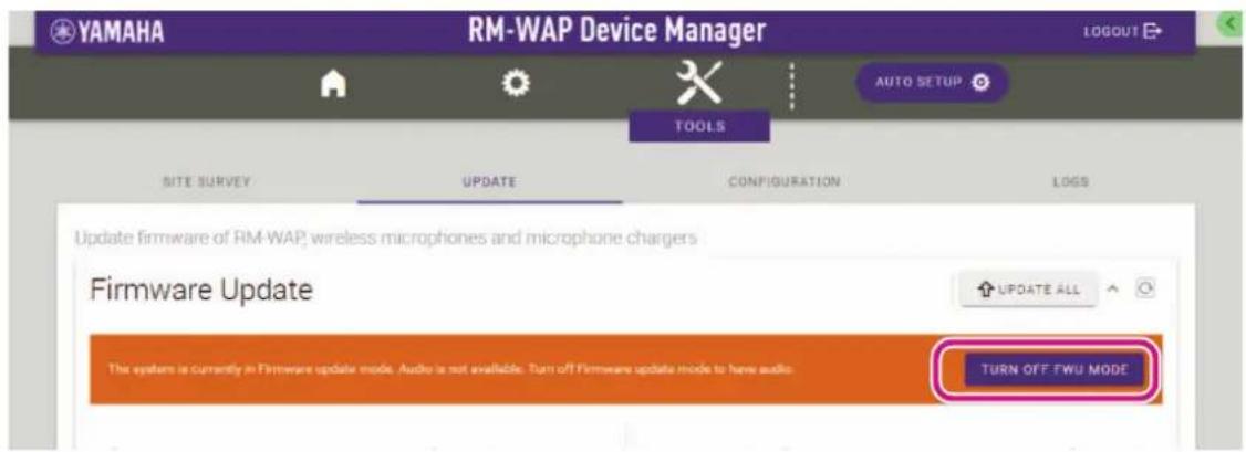
[UPDATE]
Allows you to update the firmware of access points, wireless microphones and chargers from the [UPDATE] window.
IMPORTANT: • Be sure to click the [TURN ON FWU MODE] button before updating the firmware.
- Be sure to click the [TURN OFF FWU MODE] button after updating the firmware.
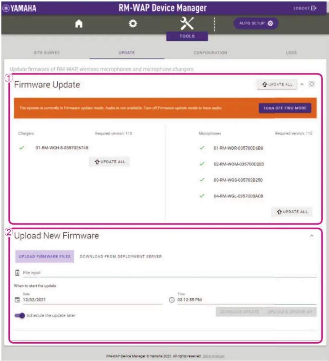
①[Firmware Update]
Allows you to update the firmware of the charger and microphones by clicking the [UPDATE ALL] button.
②[Upload New Firmware]
- Allows you to update the firmware of the access point. Click 📋, select the firmware, and then click the [UPLOAD & UPDATE AP] button.
NOTE: Alternatively, you can drag the firmware directly to the underlined area. The firmware can also be updated from the deployment server.
- Allows you to specify that the update will be performed automatically at the specified time.
[CONFIGURATION]
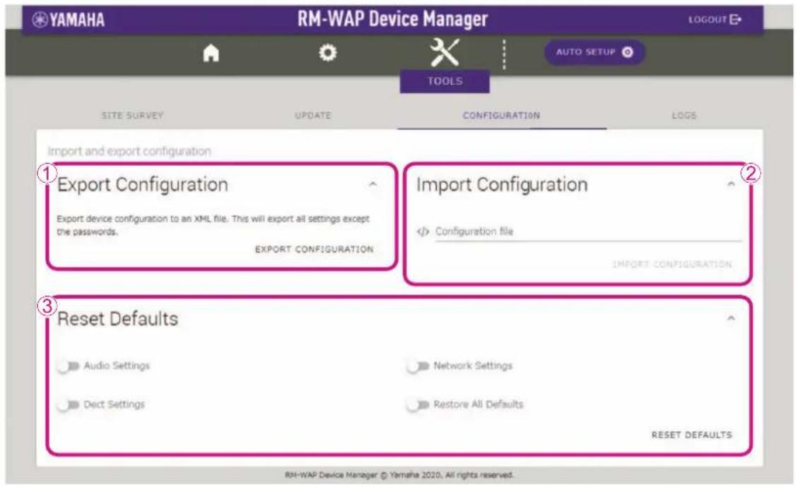
①[Export Configuration]
Allows you to export the settings by clicking the [EXPORT CONFIGURATION] button.
②[Import Configuration]
Allows you to import settings. Click </>, select a settings file, and then click the [IMPORT CONFIGURATION] button.
NOTE: • Create the settings file to be imported by editing the one exported in ①.
• Alternatively, you can drag the settings file directly to the underlined area.
③[Reset Defaults]
Allows you to reset the settings by clicking the [RESET DEFAULTS] button.
IMPORTANT: Be sure to check what is to be reset before doing it.
[LOGS]
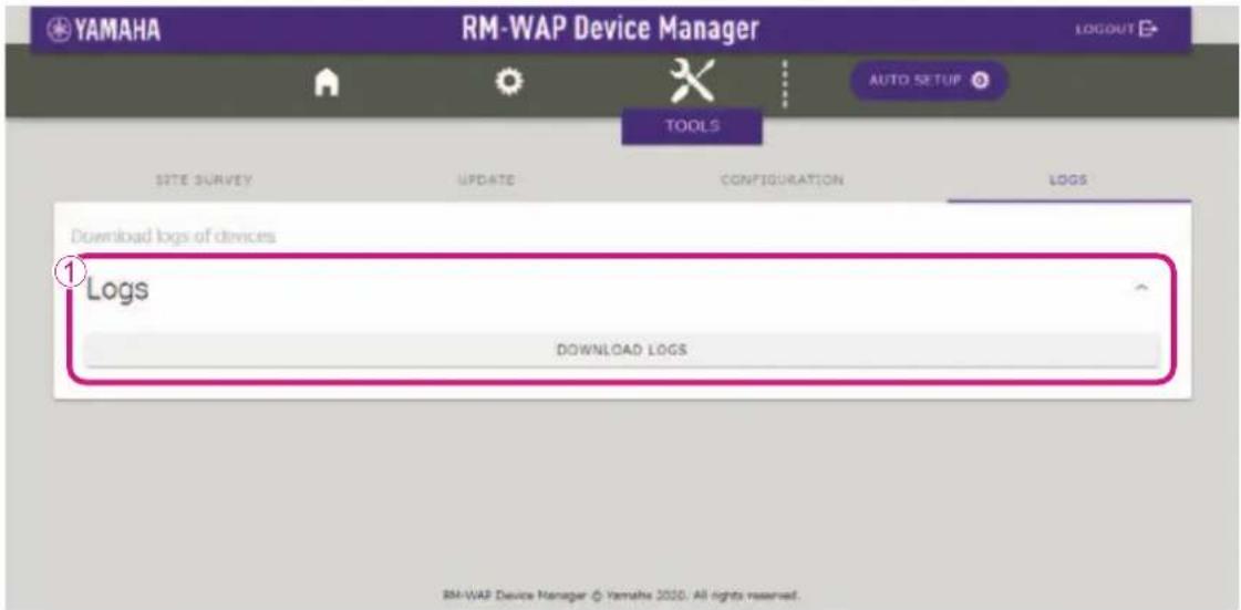
①[Logs]
Allows you to download logs by clicking the [DOWNLOAD LOGS] button.
MAIN SPECIFICATIONS
RM-WAP-8
General specifications
| Dimensions W 171.2 mm × D 172.5 mm × H 42.8 mm | |
| Weight 650 g (including mounting bracket) | |
| Power requirements PoE (IEEE802.3af), 48 V DC | |
| Maximum power consumption 48 V, 0.2 A | |
| In operation | Temperature 0 °C – 40 °C |
| Humidity 20% – 85% (no condensation) | |
| Storage | Temperature –20 °C – 60 °C |
| Humidity 10% – 90% (no condensation) | |
| Indicators | |
| Maximum number of connections to RM-CR 2 | |
| Accessories | |
Network specifications
| Dante/PoE port | • Dante audio/Dante control• External control• PoE• Cable requirements: CAT5e or higher, STP |
Audio specifications
| Sampling rate 48 kHz | |
| Bit depth | 24-bit |
| Audio input/output (Dante) | 8 outout1-out8: Mic input signals (maximum 8) |
Wireless specifications
| Supported standard 1.9 GHz DECT standard | |
| Radio frequency | • USA/Canada: 1920.0 MHz – 1930.0 MHz• Europe/Northern Europe/UK/Australia/New Zealand: 1880.0 MHz – 1900.0 MHz• Japan: 1893.5 MHz – 1906.1 MHz |
| Maximum output power (EIRP) | • USA/Canada: 23.5 dBm• Europe/Northern Europe/UK/Australia/New Zealand/Japan: 26.5 dBm |
| Antenna (built-in) | Supports space diversity |
| Use | • Audio communication and control between access point and microphone• Control between access point and charger |
| Maximum coverage distance | 50 m (depends on the usage environment) |
| Encryption method | AES (256-bit) |
General specifications
| Dimensions | RM-WOMRM-WDR | W 89.0 mm × D 89.0 mm × H 26.0 mm |
| RM-WGL | W 89.0 mm × D 89.0 mm × H 308.4 mm | |
| RM-WGS | W 89.0 mm × D 89.0 mm × H 171.2 mm | |
| Weight | RM-WOM 126 g | |
| RM-WDR 130 g | ||
| RM-WGL 152 g | ||
| RM-WGS 140 g | ||
| Power requirement | RM-WBT (lithium-ion battery)Output: 3.60 V, 2350 mAh | |
| Maximum power consumption 5 V, 0.7 A | ||
| In operation | Temperature 0 °C | - 40 °C |
| Humidity 20% - | 85% (no condensation) | |
| In charging | Temperature 5 °C | - 40 °C |
| Humidity 20% - | 85% (no condensation) | |
| Storage | Temperature -20 °C | - 60 °C |
| Humidity 10% - | 90% (no condensation) | |
| Indicators | RM-WOMRM-WDR | • Mic• B at t e r y |
| RM-WGLRM-WGS | • Mic• R i n g• B at t e r y | |
| Accessories | RM-WOMRM-WDR | • RM-WBT (battery) :1• Owner's Manual (this document) :1 |
| RM-WGLRM-WGS | • Windscreen :1• RM-WBT (battery) :1• Owner's Manual (this document) :1 | |
Audio specifications
| Frequency response | 160 Hz – 16 kHz (-10 dB) | |
| Sampling rate 48 kHz | ||
| Bit depth 24-bit | ||
| Latency | RM-WGL RM-WGS | 30 – 35 ms nominal (no sound processing, High Quality mode) / 110 ms nominal (with sound processing, High Quality mode) |
| RM-WDR RM-WOM | 110 ms nominal (with sound processing, High Quality mode) | |
| Maximum input level of SPL (0 dBFS) | RM-WOM 99.4 dB SPL | |
| RM-WDR 100.2 dB SPL | ||
| RM-WGL RM-WGS | 106.2 dB SPL | |
| Self noise | RM-WOM -23.0 dBA SPL | |
| RM-WDR -24.7 dBA SPL | ||
| RM-WGL RM-WGS | -19.3 dBA SPL | |
| SNR (Ref. 94 dB SPL at 1 kHz) | RM-WOM 117.0 dBA | |
| RM-WDR 118.7 dBA | ||
| RM-WGL RM-WGS | 113.3 dBA | |
| Sensitivity | RM-WOM -5.4 dBFS/Pa | |
| RM-WDR -62 dBFS/Pa | ||
| RM-WGL RM-WGS | -12.2 dBFS/Pa | |
| Dynamic range | RM-WOM 122.4 dBA | |
| RM-WDR 124.9 dBA | ||
| RM-WGL RM-WGS | 125.5 dBA | |
Wireless specifications
| Supported standard 1.9 GHz DECT standard | |
| Radio frequency | • USA/Canada: 1920.0 MHz – 1930.0 MHz• Europe/Northern Europe/UK/Australia/New Zealand: 1880.0 MHz – 1900.0 MHz• Japan: 1893.5 MHz – 1906.1 MHz |
| Maximum output power (EIRP) | • USA/Canada: 23.5 dBm• Europe/Northern Europe/UK/Australia/New Zealand/Japan: 26.5 dBm |
| Antenna (built-in) Supports space diversity | |
| Use Audio communication and control between access point and microphone | |
| Maximum coverage distance 50 m (depends on the usage environment) | |
| Encryption method AES (256-bit) | |
General specifications
| Dimensions W 304.0 mm x D 188.0 mm | x H 41.5 mm | |
| Weight 800 g | ||
| Power requirement | P16V2.4A-R (AC adaptor)Output: 16.0 V DC, 2.4 A ◇-C-◇ | |
| Maximum power consumption 16 V, 2.0 | A | |
| In operation | Temperature 0 °C | -40°C |
| Humidity 20% - | 85% (no condensation) | |
| Storage | Temperature -20 °C | -60°C |
| Humidity 10% - | 90% (no condensation) | |
| Indicator Activate | ||
| Accessories | • P16V2.4A-R (AC adaptor) :1• Power cord : 1 or 3• Owner's Manual (this document) :1 | |
Wireless specifications
| Supported standard 1.9 GHz DECT standard | |
| Radio frequency | • USA/Canada: 1920.0 MHz – 1930.0 MHz• Europe/Northern Europe/UK/Australia/New Zealand: 1880.0 MHz – 1900.0 MHz• Japan: 1893.5 MHz – 1906.1 MHz |
| Maximum output power (EIRP) | • USA/Canada: 23.5 dBm• Europe/Northern Europe/UK/Australia/New Zealand/Japan: 26.5 dBm |
| Antenna (built-in) | Supports space diversity |
| Use | Control between access point and charger |
| Maximum coverage distance | 50 m (depends on the usage environment) |
| Encryption method | AES (256-bit) |