Rotary 500HVG - Laser pointer ADA - Free user manual and instructions
Find the device manual for free Rotary 500HVG ADA in PDF.

User questions about Rotary 500HVG ADA
0 question about this device. Answer the ones you know or ask your own.
Ask a new question about this device
Download the instructions for your Laser pointer in PDF format for free! Find your manual Rotary 500HVG - ADA and take your electronic device back in hand. On this page are published all the documents necessary for the use of your device. Rotary 500HVG by ADA.
USER MANUAL Rotary 500HVG ADA
MEASUREMENT FOUNDATION
Operating manual ROTARY 500 HV Servo
Rotating laser level

natural_image
Red and black industrial water leveler device with yellow and black buttons (no visible text or symbols)Manufacturer: ADAINSTRUMENTS
Address: WWW.ADAINSTRUMENTS.COM

ROTARY 500 HV Servo
ENG
Table of contents
- Kit 3
- Application 3
- Specifications 4
- Overview. 6
- Features....8
- Operating Instructions 9
- Care and Maintenance 16
- Field Calibration Test ..... 17
- Power Supply 19
- Warranty 21
-
Exceptions from responsibility....21
-
Appendix 1- «Certificate of acceptance and sale»
-
Appendix 2- «Warranty card»

ROTARY 500 HV Servo
1. Kit
- Rotating laser level
• Universal wall mounting - Accumulators
- Battery charger
- Laser beam receiver
- Mount receiver
- Laser glasses
- Magnetic target
- Remote control
- Operating manual
Options can be changed by the manufacturer without notice.
2. Applications
ROTARY 500 HV Servo has been designed for use in most areas of construction, for example:
- Laying foundations
• Wall and fence construction - Laying sloped water and sewerage lines
- Laying flooring
- Hanging acoustic ceilings
• Installing partitions and drywall

ROTARY 500 HV Servo
- Specifications
| Product ROTARY 500 HV Servo | |
| Horizontal/VerticalBeam Accuracy | ±0.1mm/m±20" |
| Plumb Down/ Up Point Accuracy ±1.5mm/1.5m | |
| Self Leveling Range ±5° | |
| Water & dust-proof Indoor/outdoor IP 64 (InternationalElectrotechnical Commission) | |
| RecommendedWorking Range | 1640 ft (500 m) diameterwith Laser Detector |
| Laser Source 635 nm laser diode | |
| Classification Class II | |
| Tripod mount 5/8" | |
| Rotational Speed (rpm) 0 (stationary point), 60, 120, 300, 600 rpm | |
| Rotational Coverage (scanning function) 0° (stationary point), 10°,45°,90°,180° | |

ROTARY 500 HV Servo
| Effective Working Temperature -14°F – 113°F (-10°C – 45°C) | |
| Remote Control Distance Approx. 65 ft (20m) | |
| Remote Control Power Supply 2 x “AAA” batteries | |
| Laser Power Supply DC 4.8-6V 4x1.2V | (4 section of C size NI-MH rechargeable batteries) |
| Laser Battery Life Approx. 20 hours of continuous use | |
| Laser Detector Power Supply One 9V alkaline battery | |
| Laser Detector Battery Life 50 hours of continuous use | |
| Weight 3.0 kg with batteries | |
| Dimensions (L x W x H) 160(L) x 160(W) x 185(H)mm | |

ROTARY 500 HV Servo
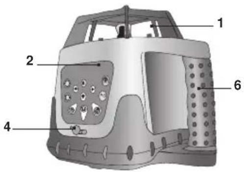
4. Overview
Laser Level
- Laser output window
- Keypad
- Battery cover
- Battery charger jack
- 5/8" tripod thread
- Handle

ROTARY 500 HV Servo
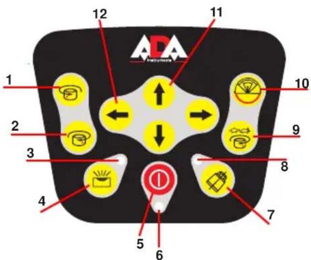
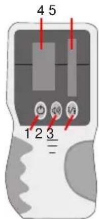
Keypad
- Counterclockwise Rotation Key
- Clockwise Rotation Key
- Manual Indicator
- Auto/Manual Key
- Power Key
- Power Indicator
- Auto-Drift Key
- Auto-Drift Indicator
- Speed Key
- Scan Mode/Scan Width
- Y-Axis arrows
- X-Axis arrows

ROTARY 500 HV Servo
5. Features
- Self-leveling electronic mechanism on slopes of ± 5^
- 360^ rotation generates a horizontal or vertical level plane
- Generates an inclined plane of any angle in both the X and Y planes (manual mode)
• Four variable speeds (0 - 600 rpm) - Adjustable scan modes create visible laser lines
- Plumb Down/Plumb Up lines
- Standard tripod thread (5/8") for vertical or horizontal use, and for attachment to angle bracket (not included)
• Work-site tough rubber bumpers and ergonomic handle - Remote Control and Laser Detector included
- Supplied with on-board internal batteries and Battery Charger-AC/DC Converter
- Shockproof protective carry case included

ROTARY 500 HV Servo
6. Operating Instructions
To get the most out of your ROTARY 500 HV Servo, please adhere carefully to the following instructions.
NOTE: Avoid setting up the laser near heavy machinery or sources of vibration that may adversely affect the leveling of the Laser.
Horizontal Plane (Automatic Mode)
Place the instrument on firm and dry ground or on a standard 5/8" tripod (not included) or ceiling to floor leveling pole (not included) or wall mount accessory (not included).
- Set up the instrument approximately level; the instrument can compensate for up to ±5^ from the horizontal plane.
- Press the Power key. The Power Indicator will light up. If the instru ment is set up outside the ±5^ limit the Manual Indicator will blink, the laser beams with not be projected and rotation will not begin.
Please turn off the instrument and set up again. - Verify that the instrument is in automatic mode – the Manual Indicator must be unlit.
- The instrument is ready for work when the Power Indicator is lit, the Manual Indicator has stopped blinking, and the laser beams are projected. The instrument is now level and the laser head will rotate clockwise at 600 rpm.
- To make the beam more visible, change the rotating speed using the speed key, or use the Laser Detector to detect the laser beam (see Laser Detector).
- Change the rotation direction by pressing the Clockwise Rotation or Counterclockwise Rotation key.

ROTARY 500 HV Servo
- Press the Auto-Drift key to automatically stop the laser beams while the unit is self-leveling. The laser beams will automatically restart when the unit is leveled.
- You can use the remote control to control the instrument (see Using the Remote Control). This option is very useful for trench work or when laying concrete.
- To turn the instrument off, press the Power key.
Vertical Plane (Automatic Mode)
The instrument can be set up to create a vertical laser line to check the vertical alignment of a wall or fence pole.
- Position the instrument on its side on the ground, on any stable surface or on a standard 5/8" tripod (not included). Set up the instrument approximately level by adjusting the legs or the tripod; the instrument can compensate for a variance of up to ±5^ from the vertical plane.
- Press the Power key. The Power Indicator will light up. If the instrument is set up outside the ±5^ limit the Manual Indicator will blink, the laser beams with not be projected and rotation will not begin. Please turn off the instrument and set up again.
- Verify that the instrument is in automatic mode – the Manual Indicator must be unlit.
- The instrument is ready for work when the Power Indicator is lit, the Manual Indicator has stopped blinking, and the laser beams are projected. The instrument is now level and the laser head will rotate clockwise at 600 rpm.
- To make the beam more visible, change the rotating speed using the speed key, or use the Laser Detector to detect the laser beam (see Laser Detector).

ROTARY 500 HV Servo
- Change the rotation direction by pressing the Clockwise Rotation or Counterclockwise Rotation key.
- Press the Auto-Drift key to automatically stop the laser beams while the unit is self-leveling. The laser beams will automatically restart when the unit is leveled.
- You can use the remote control to control the instrument (see Using the Remote Control). This option is very useful for trench work or when laying concrete.
Inclined Plane (Manual Mode)
The instrument can be set up to create a single or dual directional incline plane at any angle. This is very helpful for laying inclined concrete surfaces, ensuring run-off from pathways, and laying water and sewage lines. The instrument can be used with an angle bracket (not included), and set to any angle greater than ±5^ .
- Set up the instrument approximately level.
- Press the Power key. The power indicator will light up.
- Press the Auto/Manual Key. When the Manual Indicator lights, the instrument is in manual mode.
- Chose the X & Y direction by pressing the Clockwise Rotation or Counterclockwise Rotation Key.
- Using the X-Axis and Y-Axis arrows, adjust the slope until it suits your requirements.
- To make the beam more visible, change the rotating speed (see Changing Rotating Speed), change scanning mode (see Scan Function), or use the Laser Detector to detect the laser beam (see Laser Detector).

ROTARY 500 HV Servo
- You can use the remote control to control the instrument (see Using the Remote Control).
- To return to Automatic mode, press the Auto/Manual key. The Manual Indicator will turn off.
- To turn the instrument off, press the Power key.
Plumb Down
The Plumb Down feature enables you to center the instrument onto a selected point. It is much easier to use this feature if you set up the instrument on a tripod with a hollow connecting bolt.
- Set up the instrument on a tripod.
- Move the tripod and instrument so that they are approximately above the selected point.
- Level the instrument as in Horizontal Setup.
- Press the Power key to turn the instrument.
- Move the Plumb Down beam onto the selected point on the ground by raising and lowering the tripod legs.
- Level the instrument again, and adjust the Plumb Down beam with the tripod legs as in step 5.
- Repeat step 6 until the Plumb Down beam is sufficiently accurate for your purposes.
- If you wish to transfer a point to the ceiling, use the Plumb Up beam once the instrument is accurately centered.
Changing Rotation Speed
The laser beam is more visible when the rotating speed is slower. Change the speed of the rotating laser head by pressing the Speed key. The default option is 600 rpm. Pressing the key moves a step forward in the speed cycle (600-0-60-120-300-600-rpm).

ROTARY 500 HV Servo
Scan Function
The Scan function is used to limit the area covered by the laser beam, for safety reasons or to improve visibility and sensitivity. A smaller scan segment will be more visible than a larger one. The default mode is 360^ rotation, which provides a horizontal or inclined beam throughout the work area or room. The Scan Key changes the mode from 360^ rotation to 360^-180^-90^-45^-10^ -rotation.
- Press the Scan Key to change the scan width.
- The scan mark can be accurately positioned using the Clockwise and Counterclockwise Rotation keys.
Change the direction of rotation if there is an obstruction creating a “dead” area that no laser beam can reach.
Laser Detector
ROTARY 500 HV Servo is effective at 1640 ft (500 m) diameter when used together with the Laser
Use the Laser Detector when it is hard to see the laser beam, such as outdoors or in bright rooms. Attach the Laser Detector to a rod if the laser unit is positioned above head height.
- On/Off
- On/Off sound
- Accurate/rough mode
- LCD display
- Sensor receiver

ROTARY 500 HV Servo
Using the Laser Detector
- Press the Power key to turn on the detector.
- Press to select the fine or coarse detection mode: a symbol appears on the top of the LCD displaying which mode has been selected (course mode – top left, fine mode – top right).
- Select the mute or sound mode. The sound symbol on the LCD appears with lines when you select the sound option.
- Turn the detection window towards the laser beam and move the detector up and down following the direction of the arrow on the LCD.
- Lower the Laser Detector if the arrow points down (Beeping Sound).
- Raise the Laser Detector if the arrow points up (Beeping Sound).
- The level marks on the sides of the Laser Detector are level with the laser beam when the horizontal beam is displayed on the LCD (Continuous Sound).

ROTARY 500 HV Servo
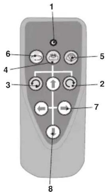
Using the Remote Control
The laser can be operated by an infra-red remote control. The remote control will only work if there is an uninterrupted line of sight between the infra-red control and the remote control sensor on the control panel. The effective range of the remote control is 65 ft (20m). The Remote Signal Indicator flashes when a signal has been sent.
- Remote Signal Indicator
- Clockwise Rotation Key
- Counterclockwise Rotation Key
- Auto/Manual Key
- Scan Mode/Scan Width
- Speed Key/Stop Key
- X-Axis arrows
- Y-Axis arrows

ROTARY 500 HV Servo
7. Care and Maintenance
Preventative Maintenance
- Store in a clean dry place, between 5^ - 131^ (-15°C - 55°C)
- Before moving or transporting the unit, ensure that it is turned off/locked.
- If the instrument is wet, dry off with a dry cloth. Do not seal the laser in the carrying case until completely dry.
- Do not attempt to dry the instrument with fire or with an electric dryer.
- Do not drop the instrument, avoid rough treatment, and avoid con stant vibration.
- Periodically check the calibration of the instrument.
- Clean with a soft cloth, slightly dampened with a soap and water solution. Do not use harsh chemicals, cleaning solvents or strong detergents.
- Keep the laser aperture clean by wiping it gently with a soft lintfree cloth.
- Keep the detection window of the Laser Detector clean by wiping it with a soft cloth moistened with glass cleaner.
- Remove batteries from the instrument during lengthy periods of non-use, and store in carrying case.
- Ensure that the instrument is turned off before removing batteries.
Repairs
• See the Warranty section at the end of this manual.
- Do not take the instrument apart or permit any unqualified person to take the laser level apart. Unauthorized servicing may cause bodily injury, irreparably damage the instrument, and invalidate the war ranty.

ROTARY 500 HV Servo
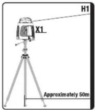
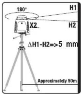
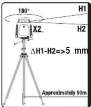
8. Field Calibration Test
The instrument leaves the factory fully calibrated. Kapro recommends that the level is checked regularly, and after the unit has been dropped or mishandled.
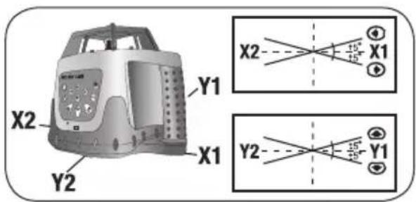
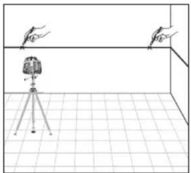
Horizontal Plane Calibration Test
- Set up the instrument approximately 150ft (50m) from a wall or a measuring staff.
- Level the instrument as accurately as possible. Position it so that the X-axis is pointing in the direction of the measuring staff or wall.
- Turn on the instrument.
- Note the height of the laser beam on the measuring staff or make a mark on the wall.
- Rotate the instrument 180°.
- Note the height of the laser beam on the measuring staff or make a new mark on the wall. The difference between the heights or marks should not exceed 5 mm.
- Repeat the procedure for the Y axis.

ROTARY 500 HV Servo
Horizontal Line Calibration Test
- Set up the instrument on a level surface, next to an unobstructed 100ft (30m) long wall.
- Level the instrument as accurately as possible.
- Turn on the instrument, mark the position of the beam next to the laser, and mark the position of the beam at a point approximately 100ft (30m) away.
- Move the instrument next to the point that you marked at a distance of 100ft (30m).
- Level the instrument as accurately as possible.
- Turn on the instrument, mark the position of the beam next to the laser, and mark the position of the beam next to the original point
- Measure the height difference between both sets of points. Ideally the two measurements should be identical; however under field conditions a difference of up to 14 inch (6mm) is acceptable.
natural_image
Simple line drawing of a room setup with a tripod-mounted device and two hand gestures above it (no text or symbols)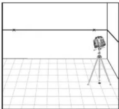
natural_image
Simple line drawing of a camera mounted on a tripod in a tiled room (no text or symbols)
ROTARY 500 HV Servo
9. Power Supply
ROTARY 500 HV Servo is supplied with on-board internal rechargeable batteries and battery charger (AC/DC Converter).
Warning: Non-rechargeable"C" batteries are not to be used!
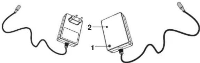
- Recharge the batteries when the Power Indicator on the keypad flashes.
- Plug the battery charger into a power source.
- Insert the plug of the battery charger into the Battery Charger Jack (see figure below).
- The indicator lamp on the battery charger illuminates when charging. The indicator lamp will flash when the battery is fully charged.
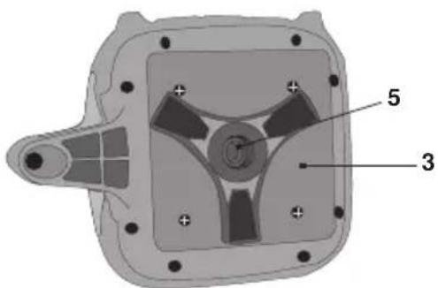
- The batteries can be removed from the instrument by unscrewing the screws holding the battery compartment cover in place.
1 Power Indicator
2 Battery Charger
natural_image
Two connected devices with wires, one labeled 1 and the other 2 (no text or symbols on the devices themselves)NOTE: The instrument can be operated while recharging. It takes approximately seven hours to fully charge a battery.

ROTARY 500 HV Servo
Laser Detector
- Press the battery compartment lock and remove the battery compartment cover.
- Remove the 9V alkaline battery.
- Replace with a new 9V alkaline battery.
Remote Control
- The battery compartment is situated in the back of the remote control.
- Slide off the battery compartment cover.
- Remove the spent batteries.
- Replace them with two "AAA" batteries.
- Replace the cover.
External Power Supply
ROTARY 500 HV Servo can use an external DC external power source. This will minimize the risk of battery failure during operation. Use only the combined Battery Charger-AC/DC Converter supplied with the Rotating Laser Level, otherwise irreparable damage will be caused to the instrument and your warranty will be

ROTARY 500 HV Servo
Warranty
This product is warranted by the manufacturer to the original purchaser to be free from defects in material and workmanship under normal use for a period of two (2) years from the date of purchase.
During the warranty period, and upon proof of purchase, the product will be repaired or replaced (with the same or similar model at manufactures option), without charge for either parts of labour.
In case of a defect please contact the dealer where you originally purchased this product. The warranty will not apply to this product if it has been misused, abused or altered. Without limiting the foregoing, leakage of the battery, bending or dropping the unit are presumed to be defects resulting from misuse or abuse.
Exceptions from responsibility
The user of this product is expected to follow the instructions given in operators' manual.
Although all instruments left our warehouse in perfect condition and adjustment the user is expected to carry out periodic checks of the product's accuracy and general performance.
The manufacturer, or its representatives, assumes no responsibility of results of a faulty or intentional usage or misuse including any direct, indirect, consequential damage, and loss of profits.
The manufacturer, or its representatives, assumes no responsibility for consequential damage, and loss of profits by any disaster (earthquake, storm, flood ...), fire, accident, or an act of a third party and/or a usage in other than usual conditions.
The manufacturer, or its representatives, assumes no responsibility for any damage, and loss of profits due to a change of data, loss of data and interruption of business etc., caused by using the product or an unusable product.
The manufacturer, or its representatives, assumes no responsibility for any damage, and loss of profits caused by usage other thsn explained in the users' manual.
The manufacturer, or its representatives, assumes no responsibility for damage caused by wrong movement or action due to connecting with other products.
WARRANTY DOESN'T EXTEND TO FOLLOWING CASES:
- If the standard or serial product number will be changed, erased, removed or wil be unreadable.
- Periodic maintenance, repair or changing parts as a result of their normal runout.
- All adaptations and modifications with the purpose of improvement and expansion of normal sphere of product application, mentioned in the service instruction, without tentative written agreement of the expert provider.
- Service by anyone other than an authorized service center.
- Damage to products or parts caused by misuse, including, without limitation, misapplication or negligence of the terms of service instruction.
- Power supply units, chargers, accessories, wearing parts.
- Products, damaged from mishandling, faulty adjustment, maintenance with low-quality and non-standard materials, presence of any liquids and foreign objects inside the product.
- Acts of God and/or actions of third persons.
- In case of unwarranted repair till the end of warranty period because of damages during the operation of the product, it's transportation and storing, warranty doesn't resume.
WARRANTY CARD
Name and model of the product ____
Serial number ____ date of sale ____
Name of commercial organization ____ stamp of commercial organization
Warranty period for the instrument exploitation is 24 months after the date of original retail purchase.
During this warranty period the owner of the product has the right for free repair of his instrument in case of manufacturing defects.
Warranty is valid only with original warranty card, fully and clear filled (stamp or mark of thr seller is obligatory).
Technical examination of instruments for fault identification which is under the warranty, is made only in the authorized service center.
In no event shall manufacturer be liable before the client for direct or consequential damages, loss of profit or any other damage which occur in the result of the instrument outage.
The product is received in the state of operability, without any visible damages, in full completeness. It is tested in my presence. I have no complaints to the product quality. I am familiar with the conditions of warranty service and i agree.
purchaser signature ____
Certificate of acceptance and sale
No
name and model of the instrument
Corresponds to
designation of standard and technical requirements
Data of issue
Stamp of quality control department
Price
Sold
Date of sale
name of commercial establishment

MEASUREMENT FOUNDATION
natural_image
Red and black scientific instrument with yellow and black buttons, no visible text or symbols
ROTARY 500 HV Servo
Клавишная панель

ROTARY 500 HV Servo
natural_image
Line drawing of a room interior with a tripod-mounted camera and two hand gestures above it (no text or symbols)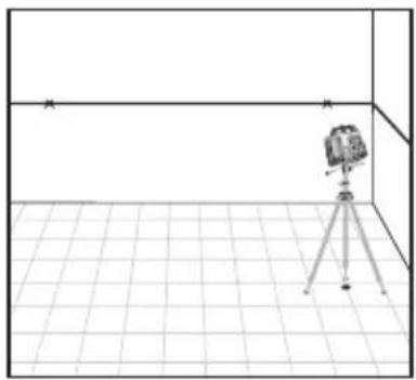
natural_image
Simple line drawing of a camera on a tripod inside a tiled room (no text or symbols)
ROTARY 500 HV Servo
9. Источник питания
natural_image
Two connected electrical devices with wires, labeled 1 and 2 (no text or symbols beyond labels)MEASUREMENT FOUNDATION
WWW.ADAINSTRUMENTS.COM