Ears - Audio accessory Mutable Instruments - Free user manual and instructions
Find the device manual for free Ears Mutable Instruments in PDF.

| Type | Contact microphone module for Eurorack |
| Dimensions | 4 HP (approx. 20 mm wide) |
| Depth | 32 mm |
| Weight | 50 g |
| Power supply | +12V and -12V via Eurorack bus board |
| Current draw | +12V: 10 mA, -12V: 5 mA |
| Inputs | 1x 3.5mm mono jack for external signal (preamp mode) |
| Outputs | 1x 3.5mm mono jack (envelope follower output), 1x 3.5mm mono jack (audio output) |
| Main functions | Contact microphone preamplifier, envelope follower, gate extractor |
| Controls | Gain trim pot, sensitivity trim pot, threshold trim pot |
| Indicators | LED for gate/trigger status |
| Materials | PCB with RoHS compliant components, aluminum front panel |
| Compatibility | Any Eurorack case with standard power header |
| Operating temperature | 0°C to 50°C |
| Storage temperature | -20°C to 60°C |
| Maintenance | Keep dry; clean front panel with a soft cloth |
| Safety | Do not exceed ±12V supply voltage; connect/disconnect only when power is off |
| Repairability | DIY-friendly through-hole components; schematics available online |
| Additional information | Includes piezo contact microphone element with adhesive pad |
Frequently Asked Questions - Ears Mutable Instruments
User questions about Ears Mutable Instruments
0 question about this device. Answer the ones you know or ask your own.
Ask a new question about this device
Download the instructions for your Audio accessory in PDF format for free! Find your manual Ears - Mutable Instruments and take your electronic device back in hand. On this page are published all the documents necessary for the use of your device. Ears by Mutable Instruments.
USER MANUAL Ears Mutable Instruments
Our take on Tom Whitwell's Mikrophonie module, Ears is a perfect match for physical synthesis modules like Rings or Elements, but it can also be the gateway between external audio sources and your modular system.
Installation
Ears requires a -12V / +12V power supply (2x5 pin connector).
The ribbon cable connector must be aligned so that the red stripe of the ribbon cable (-12V) is on the same side of the module's power header as the "Red stripe" marking on the board. The module draws 5mA from both the +12V and the -12V supply rails.
The full manual can be found online at mutable-instruments.net/modules/ears/manual
For help and discussions, head to mutable-instruments.net/forum
FC CE
Please refer to the online manual for detailed information regarding compliance with EMC directives

Mutable Instruments

natural_image
Abstract pink square icon with concentric circles and a central dot (no text or symbols)Ears
Contact microphone
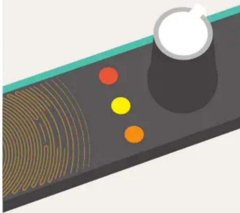
natural_image
Illustration of a fingerprint pattern on a surface with three colored dots (red, yellow, orange) and a white cylindrical object on top (no text or symbols)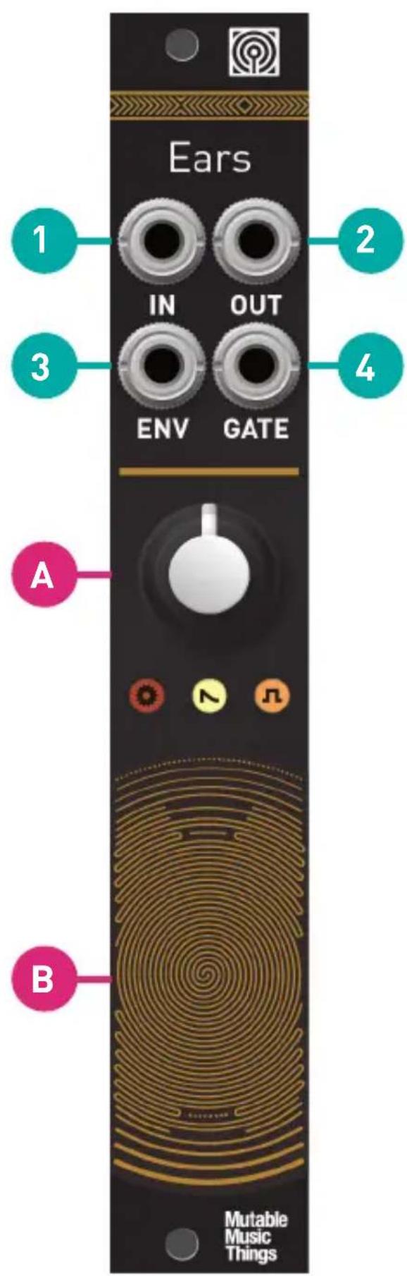
A. Gain control, 0 to 40dB (loud! may cause clipping).
B. Contact microphone.
- Hi-Z Audio input. Amplifies an external source. Patching a cable here disconnects the contact microphone.
- Audio output. The red LED indicates clipping.
- Envelope CV output. The white LED indicates the envelope CV level.
- Gate output. Emits +8V when the envelope exceeds a threshold. Indicator: orange LED.
The jumpers at the back of the module adjust the response of the envelope follower and gate detector.
Envelope Follower

Gate
Detector


The last setting is obtained by removing the jumper.