Bolt 4K TX Module - Hi-Fi System Teradek - Free user manual and instructions
Find the device manual for free Bolt 4K TX Module Teradek in PDF.

User questions about Bolt 4K TX Module Teradek
0 question about this device. Answer the ones you know or ask your own.
Ask a new question about this device
Download the instructions for your Hi-Fi System in PDF format for free! Find your manual Bolt 4K TX Module - Teradek and take your electronic device back in hand. On this page are published all the documents necessary for the use of your device. Bolt 4K TX Module by Teradek.
USER MANUAL Bolt 4K TX Module Teradek
Zero Delay Wireless Transmission System
Reference Guide
TABLE OF CONTENTS
Physical Properties 2
Getting Started 4
Device Operation 4
Power and Connect 4
Power Connector/Pin-Out 6
Custom 3rd Party Cables 6
12G-SDI Input/Output Cables 6
Pairing....6
Bolt App....8
Mounting.... 10
Vertical and Horizontal Antennas 10
Recommended Antenna Orientation 10
Bolt Panel Antenna 11
Device Placement 12
Device Settings 13
Transmitter Display Operation.... 15
Receiver Display/OSD Operation.... 19
Bolt Manager 25
Troubleshooting/FAQ 27
Frequencies by Region 29
Technical Specifications 30
Regulatory Information 38
Product Information 38
Safety Instructions 38
Warning 38
Antenna 38
A/C Power Adapter 38
Battery 38
RF Modules.... 39
Unintentional Radio Interference 41
Radio Transmitters.... 41
EC Declaration of Conformity 43
Waste Electrical and Electronic Equipment .... 43
Support Resources 43
Disclaimer 43
BOLT 4K
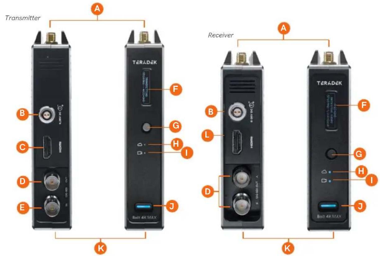
BOLT 4K LT
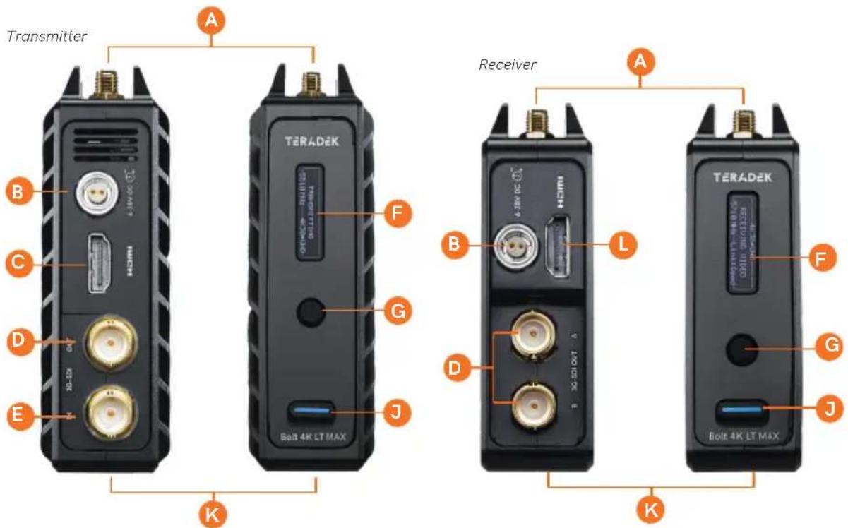
A:RP-SMA connectors
B: 6-28V DC power input
C: HDMI input
D: SDI output
E: SDI input
F: OLED display
G: Menu joystick
H: Network status
I: Video status
J: Power switch
K:Micro-USB (not shown)
L: HDMI output
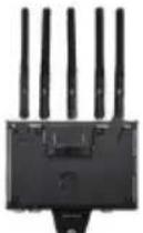
BOLT 4K MONITOR MODULE (TX/RX)
Top
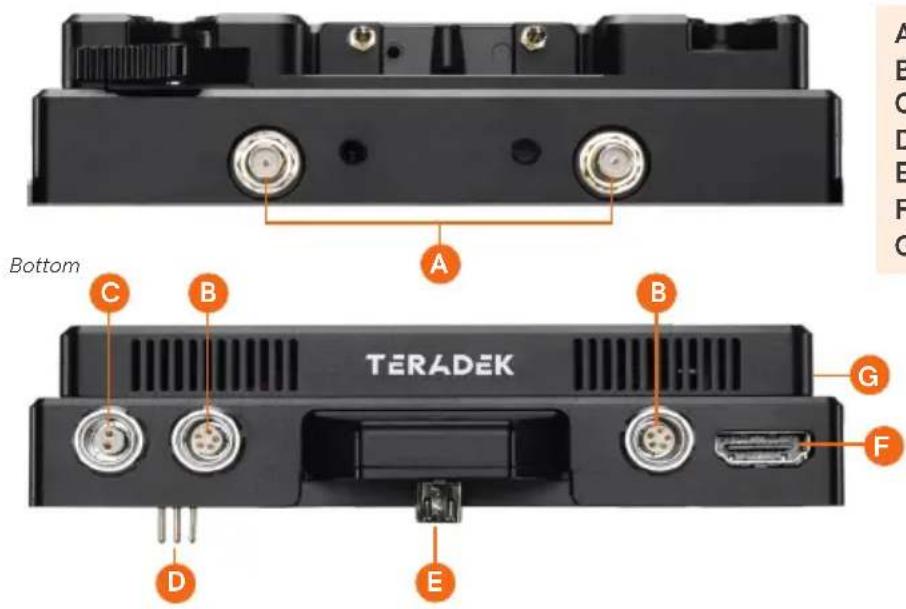
A: RP-SMA connectors
B: AUX input
C: 6-18V DC power input
D: Compression pins
E: Micro USB
F: HDMI output
G: P-Tap output
BOLT PANEL ANTENNA V.4
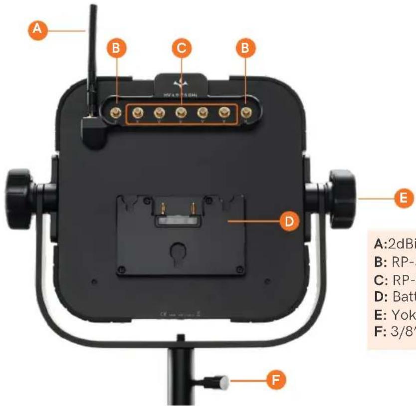
A:2dBi Omnidirectional antenna
B: RP-SMA connectors (horizontal)
C: RP-SMA connectors (vertical)
D: Battery plate
E: Yoke assembly
F: 3/8" Light stand adapter
The Bolt Panel Antenna has both vertical (C) and horizontal (B) antenna connectors. The transmitter's antenna configuration will determine which Panel RP-SMA connectors you use with the receiver. For more information, go to Vertical and Horizontal Antennas on pg.10.
DEVICE OPERATION
- For best results when using multiple Bolt systems in the same area, place the transmitters and receivers a few feet apart from each other.
- Operation of other wireless equipment may interfere with the Bolt. Try to separate other wireless transmitters and receivers as much as possible.
POWER AND CONNECT (BOLT 4K/4K LT)
1 Connect the output from your video source to either the SDI or HDMI input (C or E) on the Bolt transmitter. Connect either the SDI or HDMI output (D or L) from the Bolt receiver to the video input on your monitor.
NOTE: If mounting the receiver upright on a stand above the monitor, use a right-angle SDI adapter to relieve any strain caused by the weight of the cable, and to avoid damaging the SDI output's internal connectors.
2 Connect power to the Bolt transmitter and receiver with the included A/C adapter, or if both devices are equipped with battery plate accessories, attach a compatible battery (Gold or V mount).
3 Attach the antennas to both the transmitter and the receiver.
If using Horizontally Polarized "H" antennas:
- Bolt 4K transmitters - Attach two 2dBi antennas to the transmitter's two center connectors and the two "H" antennas to the left and right connectors.
- Bolt 4K LT transmitters - Attach one "H" antenna to the connector in front of the transmitter (closest to the front panel display), and one 2dBi antenna to the opposite connector.
- Bolt 4K/Bolt 4K LT receivers - Attach the three 2dBi antennas to the receiver's center connectors and the two "H" antennas to the left and right connectors.
If using a Bolt Panel Antenna with the receiver (1500 or MAX only):
Mount the receiver to the back of the antenna, then connect the five RP-SMA connectors to the center connectors labeled V using the included extension cables. If the transmitter is using horizontal antennas, attach the receiver's two outward connectors to the antenna's two external connectors labeled H (see page 11).
4 Move the power switches on both the transmitter and receiver (J) to the ON position. Video appears within a few seconds.
POWER AND CONNECT (BOLT 4K MONITOR MODULE)
1 Remove the battery plate from the back of the Smart 7 monitor.
2 • TX Module - Detach the cover plate from the back of the Bolt 4K Monitor Module to expose the JST connector.
- RX Module - Remove the battery plate from the back of the Bolt 4K Monitor Module to expose the two top mounting holes.
NOTE: There is no need to disconnect the JST Connector.
3 Place the monitor module firmly against the back of the Smart 7 monitor. Ensure the two top mounting holes, connector pins, and micro USB align with their corresponding terminals.
4 Insert two M3 socket-head screws through the two top mounting holes on the monitor module and into the back of the monitor (see image). DO NOT OVER-TIGHTEN.
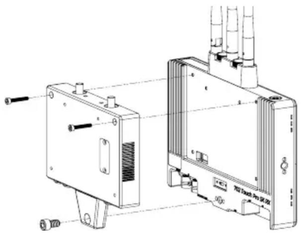
natural_image
Technical line drawing of a device housing with ports and connectors (no text or symbols)5 • TX Module - (OPTIONAL) Attach an L-series battery plate to the monitor module, then tighten the four Phillips screws.
- RX Module - Reattach the battery plate to the monitor module, then tighten the four Phillips screws.
NOTE: Before attaching the battery plate to the monitor module, ensure the wires are tucked into the plate so that they do not obstruct the release button's operation.
6 Insert, then tighten the 1/4"-20 hex screw to secure the monitor module assembly against the back of the monitor (see image). DO NOT OVER-TIGHTEN.
7 Attach a compatible battery to the battery plate (optional for TX Module), or connect power to the module's 6-18V DC input using the included A/C adapter.
NOTE: Ensure the A/C adapter is connected to the module and NOT the monitor.
8 Attach antennas to the monitor module via the threaded RP-SMA connectors, then connect an HDMI cable from the module to the monitor.
9 Turn the system on by pressing and holding down the monitor's power button.
POWER CONNECTOR/PIN OUT
Bolt devices use a locking 2-pin power connector similar to the 0B 302 series LEMO connector.

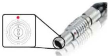
natural_image
Close-up of a metallic cylindrical mechanical component with a red dot and concentric circular features, no visible text or symbols.* Pin 1 is closest to the red dot on the connector
CUSTOM/3RD PARTY POWER CABLES
- Test the power cable polarity with ONLY the power cable connected to Bolt. Do not connect video cables.
- Check the power cable for shorts and proper grounding.
CAUTION:
Using a reverse polarity or improperly-constructed power cable can damage the product and is not covered under warranty.
12G-SDI CABLES
Bolt 4K devices require the use of 12G-SDI cables in order to reliably transport 12G video signals, and are included as a standard item. Ensure that your cables are rated for compatibility with your camera's output.
PAIRING
Bolt devices purchased as a set (TX and RX), are paired by default, requiring no additional configuration. Bolt devices purchased separately need to be paired using the device's front panel (OLED) menu, Bolt Manager, or the Bolt App.
NOTE: Before starting either pairing process, ensure that both the transmitter and receiver have the same firmware version and have Bluetooth enabled.
PAIRING VIA THE FRONT PANEL MENU
1 Using the Menu Joystick (G), navigate to the Pairing menu on both the transmitter and the receiver.
2 Select Pairing to begin the pairing process. The transmitter will begin scanning for a receiver within range and automatically pair to the receiver.
3 Once paired, the front panel will indicate whether or not Pairing is successful.
PAIRING TIPS
If you're having trouble getting units to pair, we recommend keeping the transmitter and receiver six feet apart when pairing (if antennas are connected). Without antennas, they can be closer. Keep all other RF devices nearby turned off or out of range to ensure the transmitter and receiver are only detecting each other. To eliminate any chance of interference, perform the Wired Pairing process via Bolt Manager.
PAIRING VIA MONITOR (TX MODULE)
1 Swipe right on the monitor's touchscreen until Monitor Settings is displayed, then scroll down the left column and navigate to Accessories>App Connection, then select Enable Device Discovery.
2 Scroll back up and tap to select the TERADEK BOLT 4K option, then tap Pair new transmitter (TX).
3 Enable Pairing on the Bolt 4K receiver by selecting Pair on the front panel menu. The TX module will begin scanning for receivers to automatically pair with.
4 Once the devices are paired successfully, tap Accept to dismiss the menu. If pairing fails, try again.
PAIRING VIA MONITOR (RX MODULE)
1 Swipe right on the monitor's touchscreen, then tap on the Full Settings option once it appears.
2 Tap to select the TERADEK BOLT 4K option, then tap Pair new transmitter (TX).
3 Enable Pairing on the Bolt 4K receiver by selecting Pair on the transmitter's front panel menu. The RX module will begin scanning for the transmitter to automatically pair with.
4 Once the devices are paired successfully, tap Accept to dismiss the menu. If pairing fails, try again.
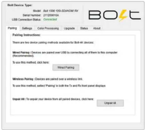
WIRED PAIRING VIA BOLT MANAGER
1 Connect both the transmitter and receiver(s) to your computer via USB.
2 Open Bolt Manager, select the Pairing tab, then tap the Wired Pairing button.
3 Select the devices you want to pair, then click the Pair Devices button. Bolt Manager will indicate whether or not Pairing is successful.
PAIRING VIA THE BOLT APP
1 Open the Bolt App from your iOS or Android device, then tap the Pairing button.
2 Select the transmitter you wish to pair, then tap the Next button.
3 Select the receiver(s) you wish to pair with the transmitter, then tap the Pair! button. The Bolt App will indicate when the pairing process is completed.
BOLT APP
Use the Bolt App to remotely manage and monitor every parameter of Bolt 4K including pairing, frequency selection, and 3D LUTs.
CONNECT VIA BLUETOOTH
1 Download the Bolt App.
2 Enable Bluetooth on your iOS or Android device.
3 Navigate to the Bluetooth menu on both the transmitter and receiver, then select Enable.
4 Open the Bolt App from your iOS or Android device, then tap the Bolt Devices button.
5 Select the device(s) you want to pair or monitor.

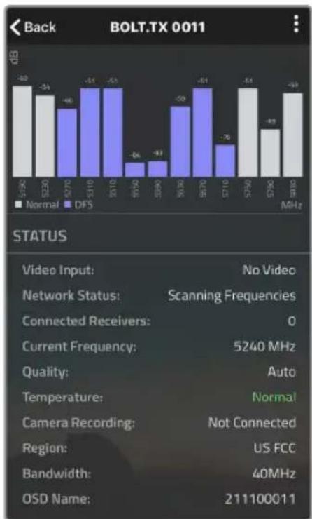
TRANSMITTER STATUS DISPLAY
Settings (Menu descriptions listed on pg. 11) - Tap the: button at the top of the screen to customize the transmitter's various settings.
Spectrum Analyzer - Detects congestion in the area and determines which frequencies are available to use. Each bar represents a frequency, and the height represents the amount of congestion in that frequency; the higher the bar, the more congested that frequency is. Make sure to always select the shortest, least congested bar.
Status - Displays the current status of:
- Video input
- Temperature
- Network
- Camera recording
- Connected receivers
- Region
- Current frequency
- Bandwidth
• Quality - OSD name
bar
Back BOLT.TX 0011 | Frequency | Normal (dB) | DFS (dB) | | :--- | :--- | :--- | | 5-5Hz | -30 | - | | 5-20 | -34 | -40 | | 5-70 | - | -51 | | 5-10 | - | -51 | | 10-10 | - | -64 | | 10-20 | - | -47 | | 20-30 | - | -50 | | 30-70 | - | -51 | | 7-10 | - | -76 | | 7-20 | - | -51 | | 8-20 | -49 | - | | 8-30 | - | -49 | STATUS Video Input: No Video Network Status: Scanning Frequencies Connected Receivers: 0 Current Frequency: 5240 MHz Quality: Auto Temperature: Normal Camera Recording: Not Connected Region: US FCC Bandwidth: 40MHz OSD Name: 211100011RECEIVER STATUS DISPLAY
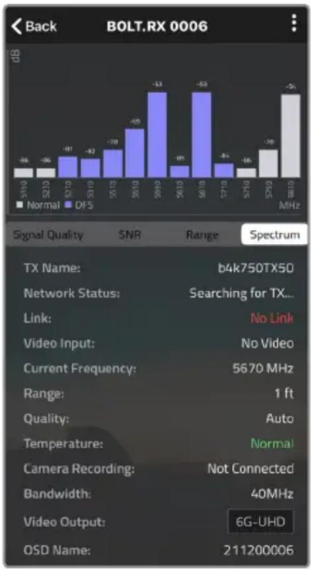
Settings (Menu descriptions listed on pg. 11) - Tap the : button at the top of the display to customize the receiver's various settings such as the output format, audio, display and OSD.
Signal Quality - Determine the quality and reliability of the signal being received.
SNR (Signal to Noise Ratio) - Compare the signal power level to the noise power level from the attached antennas.
Range Analyzer - Displays the transmission distance between the transmitter and receiver.
Spectrum Analyzer - Detects congestion in the area and determines which frequencies are available to use. Each bar represents a frequency, and the height represents the amount of congestion in that frequency; the higher the bar, the more congested that frequency is. Make sure to always select the shortest, least congested bar.
bar
Back BOLT.RX 0006 | Signal Quality | Normal (MHz) | DF5 (MHz) | Range | |---|---|---|---| | 5100 | -46 | | | | 5210 | -36 | | | | 5210 | -91 | | | | 5310 | -82 | | | | 5510 | -70 | | | | 5510 | -65 | | | | 5610 | -53 | | | | 5610 | -89 | | | | 5610 | -63 | | | | 5710 | -84 | | | | 5710 | -56 | | | | 5710 | -38 | | | | 5810 | -51 | | | Signal Quality SNR Range Spectrum TX Name: b4k750TX50 Network Status: Searching for TX... Link: No Link Video Input: No Video Current Frequency: 5670 MHz Range: 1 ft Quality: Auto Temperature: Normal Camera Recording: Not Connected Bandwidth: 40MHz Video Output: 6G-UHD OSD Name: 211200006Status - Displays the current status of:
- TX Name
- Quality
- Network
- Temperature
- Link
- Camera recording
- Video input
- Bandwidth
- Current frequency
- Video output
- Range
- OSD name
Bolt 4K transmitters and receivers require the use of external antennas for basic operation. Different conditions will determine the type, orientation, and placement of the antennas.
VERTICAL AND HORIZONTAL ANTENNAS
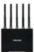
Vertical (V) antennas are included as a standard item with your Bolt 4K, offering good performance in a wide variety of short-to-medium range situations when quick setup and flexibility is key. V antennas are ideal for achieving diversity indoors. Once you move outdoors with the V antennas, the RF signals travel in a similar or identical manner towards the receiver, weakening diversity. Horizontal (H) antennas were designed for use with the V antennas. H antennas cause the RF signal from the transmitter to propagate in a perpendicular manner compared to the vertical signal from the V antenna. The H+V antenna configuration helps to maintain the quality and performance of your video transmission, especially when your signal would otherwise begin to deteriorate due to noise and/or longer ranges.
NOTE: H+V antennas must be attached to both the transmitter and receiver.
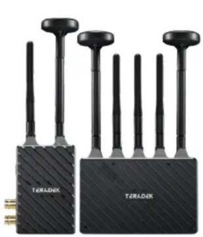
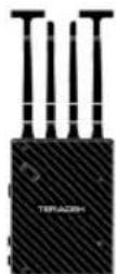
natural_image
Two black Teradek sensor devices with multiple probe-like antennas, shown from different angles (no text or symbols visible on the devices themselves)Bolt 4K LT system with H+V antennas
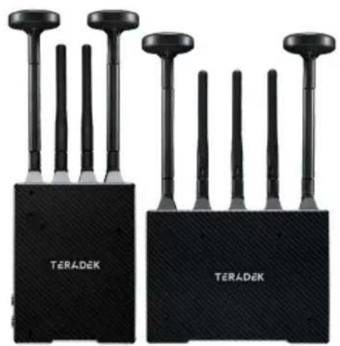
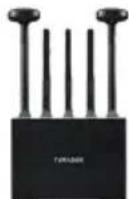
natural_image
Two black TERADEK brand speakers with antenna arrays, no visible text or symbols on the devices themselves.Bolt 4K system with H+V antennas
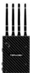
RECOMMENDED ANTENNA ORIENTATION
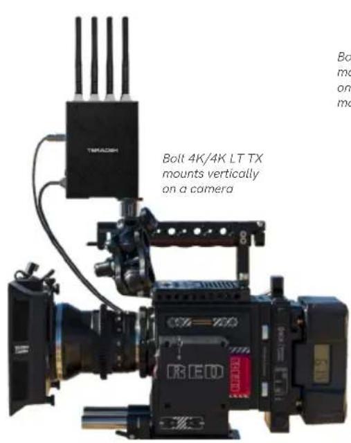
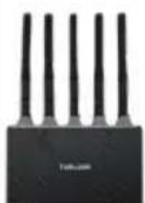
For most setups, the ideal position for the four TX antennas and the five RX antennas is perpendicular to the ground/horizontal plane so that they point straight up and down. If the transmitter is mounted at an angle or on its side, the antennas must also be arranged so that they point up. Pointing the antennas in any other direction re-orients the radiation pattern and may reduce performance.
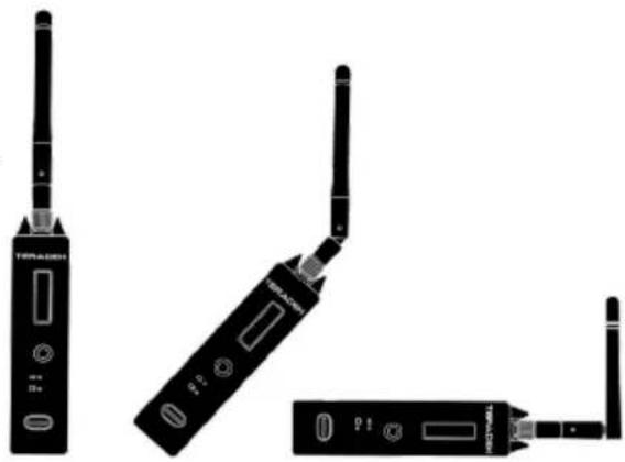
natural_image
Three black wireless devices with visible ports and antennas, no text or symbols presentExamples of Bolt 4K TX in various mounted positions
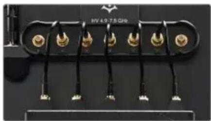
BOLT PANEL ANTENNA V.4
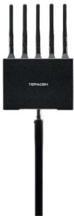
If using the Bolt Panel Antenna V.4 with your Bolt 4K/4K LT 1500 or MAX receiver, you must connect the five RP-SMA connectors from the receiver to the back of the antenna (see below for connector placement), and position the antenna so that the front (with the Teradek logo) has a clear line of sight to the transmitter.
natural_image
Close-up of a black electronic component with multiple gold connectors and terminal leads (no visible text or symbols)V antenna TX and RX configuration
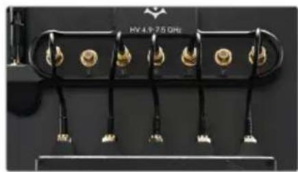
natural_image
Close-up of a black electronic device with multiple gold connectors and power cable (no visible text or symbols)H+V antenna TX and RX configuration
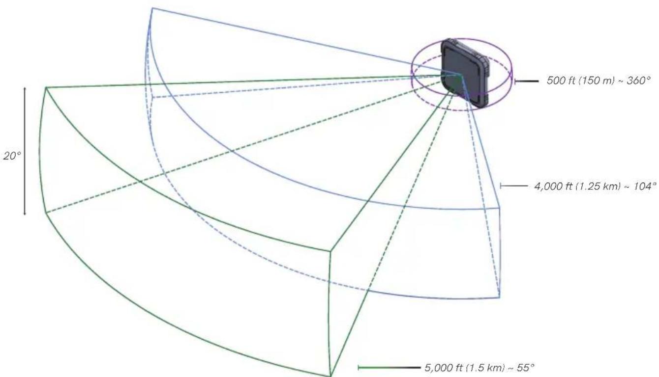
The Bolt Panel Antenna has a built-in directional antenna with a receive pattern that varies based on its distance from the transmitter. The horizontal receive angle measures 55° at 5,000 ft (1.5 km), 104° at 4,000 ft (1.25 km), and is effectively omni-directional at up to 500 ft (150 m). The vertical receive angle measures 20° at any distance. In order to maintain signal strength, you need to adjust the height of the receiver and/or the height of the transmitter accordingly so that there is no more than 20% obstruction. For more information, please visit: https://support.teradek.com/hc/en-us/articles/4405667258007-Bolt-Panel-Antenna-v4-0-Best-Practices.
For more information about the different antenna configurations for Bolt 4K, please visit: https://teradek.com/blogs/articles/what-antennas-should-i-use-with-bolt-4k?pos=1&_sid=cefeb7d2d&_ss=r.
DEVICE PLACEMENT
WITHOUT DUAL MOUNT
Bolt 4K/4K LT devices have a 1/4"-20 threaded hole (additional 3/8"-16 threaded hole on the receiver) on the bottom for mounting the included light stand adapter or any other mounting accessory.
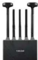
Bolt 4K/4K LT RX mounts vertically on a light stand or monitor
natural_image
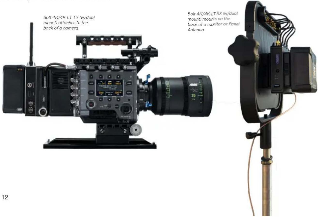
Black Teradech wireless device with five antenna ports and a tassel (no visible text or symbols on body)WITH DUAL MOUNT
Depending on the model, Bolt 4K/4K LT devices are equipped with a dual mount battery plate that allows you to attach your device to either the back of a camera, monitor, or Bolt Panel Antenna.
DEVICE SETTINGS
Bolt 4K and Bolt 4K LT transmitters and receivers share most of the same settings options. Refer to the following settings charts to verify which settings are available on your Bolt 4K unit or set.
 BOLT 4K B BOLT 4K B | 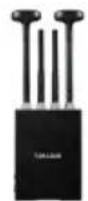 BOLT 4K MAX BOLT 4K MAX | 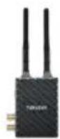 BOLT 4K LT B BOLT 4K LT B | 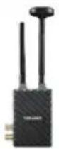 BOLT 4K LT MAX BOLT 4K LT MAX | 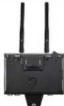 TX MODULE TX MODULE | ||
| TRANSMITTER SETTINGS | BROADCAST MODE | ● | ● | |||
| FIXED FREQUENCY | ● ● | ● ● ● | ||||
| SELECTBANDWIDTH | ● ● | ● ● ● | ||||
| SELECTFREQUENCY | ● ● | ● ● ● | ||||
| VIDEO QUALITY | ● ● | ● ● ● | ||||
| - Auto Mode | ● ● | ● ● ● | ||||
| - Longer Distance Mode | ● ● | ● ● ● | ||||
| - Better Quality Mode | ● ● | ● ● ● | ||||
| - Best Quality Mode | ● ● | ● ● | ||||
| - Low Power Mode | ● | ● | ||||
| PAIR/UNPAIR | ● ● | ● ● ● | ||||
| BLUETOOTH SETTINGS | ● ● | ● ● ● | ||||
| DISPLAY SETTINGS | ● ● | ● ● | ||||
| RESET ALL SETTINGS | ● ● | ● ● | ||||
| DEVICE INFO | ● ● | ● ● ● | ||||
| FIRMWARE VERSIONS | ● ● | ● ● ● | ||||
| RENAME RX | ● | |||||
| FAN MODE | ● ● | ● | ||||
 |  |  |  |  | ||
| BOLT 4K | BOLT 4K MAX BOLT 4K LT BOLT 4K LT MAX | RX MODULE | ||||
| RECEIVER SETTINGS | SWITCH TX | ● ● | ● ● ● | |||
| FIXED FREQUENCY | ● ● | ● ● ● | ||||
| SELECT BANDWIDTH | ● ● | ● ● ● | ||||
| SELECT FREQUENCY | ● ● | ● ● ● | ||||
| SPECTRUM ANALYZER | ● ● | ● ● | ||||
| SIGNAL QUALITY GRAPH | ● ● | ● ● | ||||
| PAIR/UNPAIR | ● ● | ● ● ● | ||||
| HDMI/SDI OUTPUT FORMAT | ● | ● | ||||
| HDMI SETTINGS | ● ● | ● ● | ||||
| 3D LUT SETTINGS | ● ● | ● ● | ||||
| TEST PATTERN | ● ● | ● ● | ||||
| AUDIO SETTINGS | ● ● | ● ● | ||||
| BLUETOOTH SETTINGS | ● ● | ● ● | ||||
| VIDEO OSD SETTINGS | ● ● | ● ● | ||||
| DISPLAY SETTINGS | ● ● | ● ● | ||||
| RESET ALL SETTINGS | ● ● | ● ● | ||||
| DEVICE INFO | ● ● | ● ● ● | ||||
| FIRMWARE VERSIONS | ● ● | ● ● ● | ||||
| RENAME TX | ● | |||||
| FAN MODE | ● ● | ● | ||||
Bolt 4K's configuration menus can be accessed from either the transmitter's front panel display or from the Bolt app.
STATUS SCREENS
Press the menu joystick (G) to cycle through the status screens or to return from the menu.
- MAIN STATUS - Displays the status of the wireless receiver, along
with the current video resolution, frequency, and link quality (if connected). - INFO - Displays the current voltage and internal temperature of the unit.
- HDMI STATUS - Displays the current HDMI color output.
CONFIGURATION OPTIONS
Most of the options listed in this section can also be configured using the Bolt app. Use the Menu joystick (G) to navigate the transmitter's configuration options.
WIRELESS SETTINGS
The transmitter's Wireless Settings menu contains several configurable options to optimize your transmitter's range, quality, and reliability.
WIRELESS SETTINGS - ENABLE BROADCAST MODE (BOLT 4K MAX/4K-LT MAX ONLY)
Broadcast Mode allows you to transmit to multiple receivers simultaneously (non-DFS frequencies only), while also extending Bolt 4K's transmission range.
- Broadcast Mode Disabled
(Standard Multicast Mode) - Transmitter and connected receiver(s) coordinate and maintain two-way communication with each other to optimize frequency usage and video transmission.
- Broadcast Mode Enabled
- Data uplink channel is disabled, allowing the transmitter to connect to an unlimited number of receivers, as long as they have already been paired. To achieve even better range performance, attach the receiver to your Bolt Panel Antenna while in Broadcast Mode.
NOTE: Bolt 4K 750 and 1500 receivers will not link to a Bolt 4K MAX transmitter in Broadcast Mode, even if they were previously paired. You must use a Bolt 4K MAX receiver, otherwise the transmitter's OLED will display Broadcast Not Supported.
WIRELESS SETTINGS - ENABLE FIXED FREQUENCY
Fixed Frequency Mode bypasses any automatic frequency switching logic, allowing your Bolt 4K system to always attempt to connect on a specified frequency. Once a frequency is selected, the transmitter will only use that frequency. This allows your transmitter to link/reconnect to the receiver much faster. After enabling Fixed Frequency mode, navigate to Frequencies and select a frequency within the selected wireless region (non-DFS frequencies only). For best results, ensure that both the transmitter and receiver have Fixed Frequency Mode enabled, and use the Spectrum Analyzer (on the receiver's front panel or the Bolt app) to search for the least congested frequency to use.
- Fixed Frequency Mode Disabled
- Bolt 4K scans all available channels and repeatedly switches from one frequency to the next during transmission
- Fixed Frequency Mode Enabled
- Bolt 4K connects to one specific frequency
NOTE: By default, Bolt 4K will select the lowest available frequency from the Frequencies list if one has not been selected beforehand.
WIRELESS SETTINGS - SELECT BANDWIDTH
The Bandwidth menu lets you choose between 40MHz (default) and 20MHz operating modes. Ensure that both the transmitter and receiver are set to the same bandwidth with a resolution of up to 1080p60. For all available frequencies, refer to the FREQUENCIES BY REGION chart on page 27.
- 20MHz - Reduces the amount of bandwidth by half, effectively doubling the number of usable frequencies while decreasing interference.
- 40MHz - (Default) Increases the amount of bandwidth by bonding two 20MHz channels, allowing for faster transfer rates but increased interference.
NOTE: 20MHz mode supports HD/3G resolutions up to 1080p60. Resolutions up to 4k30 are also supported, but downscaled to 1080p before transmission (4k50/59/60 is not supported).
WIRELESS SETTINGS - SELECT FREQUENCY
The Frequencies menu contains a list of all available frequencies. Bolt 4K will automatically select an operating frequency when multiple values are selected. If both the transmitter and receiver have Fixed Frequency Mode enabled, you can only select one frequency for Bolt 4K to use. Frequencies marked with (DFS) must be scanned for one minute before they can be used, but are typically less crowded. For all available frequencies, refer to the FREQUENCIES BY REGION chart on page 27.
WIRELESS SETTINGS - VIDEO QUALITY
The Video Quality menu lets you adjust the balance between your signal's maximum range and quality according to the number of antennas used to transmit fine information. Bolt 4K has four picture quality levels that vary based on the lowest quality link or the furthest receiver.
- Auto Mode
- (Default) Transmitter automatically determines how many fine antennas are needed based on the range and signal quality
- Longer Distance Mode
- (One fine antenna) Maintains the maximum range in situations where other sources of interference might be present, but will slightly reduce your video signal's maximum quality
- Better Quality Mode
- (Two fine antennas) Maintains higher signal quality, but reduces the maximum range
- Best Quality Mode
- (Three fine antennas) Ideal for complex, high contrast scenes that require the highest possible quality
- Low Power Mode
- (One fine antenna with shorter range) Reduces the transmitter's total power consumption by about 1.5W, and may reduce any unwanted interference in multi-system environments
PAIR
Enable pairing on transmitters and receivers. Bolt 4K units purchased as a set (TX and RX) are paired by default, requiring no additional configuration. If the units were purchased separately, or if they have never been paired, you will need to complete the pairing process (page 6). Once Pairing is complete, there is no need to repeat the process unless the TX or RX's OSD name has been modified, or if the region has been changed. To confirm if your devices were paired successfully, open either the Unpair menu (TX) or the Switch TX menu (RX) and verify that the paired device is listed.
NOTE: Before starting the pairing process, ensure that both the transmitter and receiver have the same firmware version and have Bluetooth enabled.
UNPAIR
Unpair and remove devices from your unit's paired device registry. This feature is useful in situations when paired devices are no longer being used and need to either be removed from the registry, or replaced. Transmitters can store up to six paired receivers in its device registry. Pairing more receivers than the maximum six allowed will remove the first paired unit from the device registry.
BLUETOOTH SETTINGS
Use the Bluetooth menu to enable or disable Bluetooth communication.
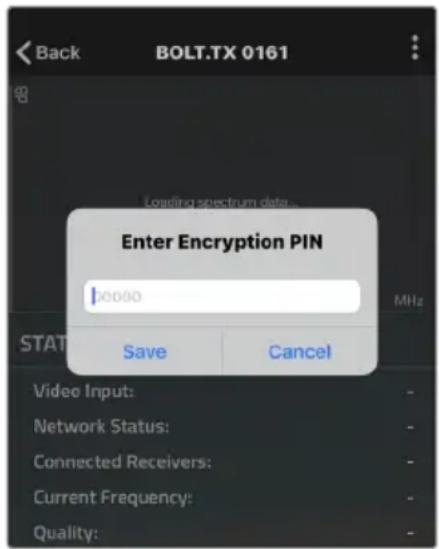
- Enable Bluetooth - Allows the transmitter and receiver to be paired and communicate with the Bolt App
- Use Bluetooth PIN - Enables the use of a PIN for authentication when using the Bolt App (see image)
- Change PIN - Press the Menu joystick towards the right to change the Bluetooth PIN
NOTE: Bluetooth is disabled by default. In order to configure your Bolt 4K devices via the Bolt App, you must first enable Bluetooth.
DISPLAY SETTINGS
Use the Display Settings to control the OLED display operation. By default, the OLED display will invert every 10 minutes. You can set the display to invert every 30 minutes (lengthens the display life), or it can dim or turn off after either 10 minutes or 10 seconds.
• Invert every 30 min
- Dim every 10 min
- Dim after 10 sec
- Invert every 30 min
- Dim every 10 min
- Dim after 10 sec
RESET ALL SETTINGS
Reset all configurable options to their factory defaults.
DEVICE INFO
Displays the model and serial number.
FIRMWARE VERSIONS
Displays the device's current firmware versions.
Bolt 4K's configuration menus can be accessed from either the receiver's front panel display or from the Bolt app. When enabled, the receiver's configuration menus are also displayed via On-Screen Display (OSD) on a connected monitor.
RECEIVER STATUS SCREENS
Press the menu joystick (G) to cycle through the status screens or to return from the menu.
- MAIN STATUS - Displays the status of the wireless receiver, along with the current video resolution, frequency, and link quality (if connected).
- TIME CODE - Displays the current time code if received from the transmitter.
- INFO - Displays the current voltage and internal temperature of the unit.
- TX INFO - Displays the name of the transmitter it is paired to.
- HDMI STATUS - Displays the current HDMI color output.
CONFIGURATION OPTIONS
Most of the options listed in this section can also be configured using the Bolt app. Use the Menu joystick (G) to navigate the configuration menus.
SWITCH TX
Bolt 4K receivers can pair with up to four transmitters at a time. Switch TX allows you to quickly switch from one paired transmitter's camera feed to another paired transmitter. This feature is especially useful in multi-camera situations when you need to switch to a different camera's view mid-shoot, without having to perform the pairing process every time.
NOTE: The transmitter(s) need to first be paired with the receiver.
WIRELESS SETTINGS
The receiver's Wireless Settings menu contains several configurable options to optimize your receiver's range, quality, and reliability.
WIRELESS SETTINGS - ENABLE FIXED FREQUENCY
Fixed Frequency Mode bypasses any automatic frequency switching logic, allowing your Bolt 4K system to always attempt to connect on a specified frequency. Once a frequency is selected, the transmitter will only use that frequency. This allows your transmitter to link/reconnect to the receiver much faster. After enabling Fixed
Frequency mode, navigate to Frequencies and select a frequency not in use (non-DFS frequencies only). For best results, ensure that both the transmitter and receiver have Fixed Frequency Mode enabled, and use the Spectrum Analyzer (on the receiver's front panel or the Bolt app) to search for the least congested frequency to use.
• Fixed Frequency Mode Disabled
- Bolt 4K scans all available channels and repeatedly switches from one frequency to the next during transmission
- Fixed Frequency Mode Enabled
- Bolt 4K connects to one specific frequency
NOTE: By default, Bolt 4K will select the lowest available frequency from the Frequencies list if one has not been selected beforehand.
WIRELESS SETTINGS - SELECT BANDWIDTH
The Bandwidth menu lets you choose between 40MHz (default) and 20MHz operating modes. Ensure that both the transmitter and receiver are set to the same bandwidth with a resolution of up to 1080p60. For all available frequencies, refer to the FREQUENCIES BY REGION chart on page 27.
- 20MHz - Reduces the amount of bandwidth by half, effectively doubling the number of usable frequencies while decreasing interference
- 40MHz - (Default) Increases the amount of bandwidth by bonding two 20MHz channels, allowing for faster transfer rates but increased interference
NOTE: 20MHz mode supports HD/3G resolutions up to 1080p60. Resolutions up to 4k30 are also supported, but downscaled to 1080p before transmission (4k50/59/60 is not supported).
WIRELESS SETTINGS - SELECT FREQUENCY
The Frequencies menu contains a list of all available frequencies. Bolt 4K will automatically select an operating frequency when multiple values are selected. If both the transmitter and receiver have Fixed Frequency Mode enabled, you can only select one frequency for Bolt 4K to use. Frequencies marked with (DFS) must be scanned for one minute before they can be used, but are typically less crowded. For all available frequencies, refer to the FREQUENCIES BY REGION chart on page 27.
SPECTRUM ANALYZER
The built-in Spectrum Analyzer provides a visual indication of channel noise and saturation across the entire available frequency range. Move the Menu joystick left and right to select a frequency, then up and down to enable or disable it.
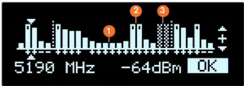
bar
| Frequency | Value | | :--- | :--- | | 5190 MHz | 1 | | -64dBm | 2 | | -64dBm | 3 | | OK | + |Frequencies are represented by bars; the higher the bar, the more congested that frequency is. Bars without a dot (1) indicate the frequency is not as saturated and can be used. Bars with a dot (2) indicate the frequency is too saturated to connect to. Faded bars (3) represent a frequency that is unavailable for use due to restrictions in particular regions.
SIGNAL QUALITY GRAPH
The Signal Quality Graph indicates the quality and reliability of the signal being received according to the amount of interference that is present between the RX and TX. Signal Quality is represented in percentages:
• Figures below 30% indicate poor signal quality
• Figures between 30% and 45% indicate fair signal quality
• Figures above 45% indicate good signal quality
PAIR
Enable pairing on transmitters and receivers. Bolt 4K units purchased as a set (TX and RX) are paired by default, requiring no additional configuration. If the units were purchased separately, or if they have never been paired, you will need to complete the pairing process (page 6). Once Pairing is complete, there is no need to repeat the process unless the TX or RX's OSD name has been modified, or if the region has been changed. To confirm if your devices were paired successfully, open the either the Unpair menu (TX) or the Switch TX menu (RX) and verify that the paired device is listed.
NOTE: Before starting the pairing process, ensure that both the transmitter and receiver have the same firmware version and have Bluetooth enabled.
UNPAIR
Unpair and remove devices from your unit's paired device registry. This feature is useful in situations when paired devices are no longer being used and need to either be removed from the registry, or replaced. Receivers can store up to four transmitters in its device registry.
HDMI/SDI OUT FORMAT (BOLT 4K ONLY)
You can choose to match the video source's resolution (Same As Input), or choose from the resolutions listed. If using the receiver with a recorder or monitor that is sensitive to video signal changes, select Continuous Output to ensure the signal stays constant even if the link is interrupted. Keep in mind that selecting Continuous Output adds a small delay to the video output. Selecting SD, HD, or 6G-UHD matches the video source's frame rate while adjusting the resolution. This is useful for when you need to down-convert a 4K video to display on an HD monitor.
• Continuous Output
- Video signal output stays constant when using a monitor or recorder that is sensitive to video signal changes
- Same As Input
- Matches the transmitter's video source resolution.
• SD
- Matches the TX frame rate and outputs SD resolution
• HD
- Matches the TX frame rate and outputs1920x1080p
- 6K-UHD
- Matches the TX frame rate and outputs 3840x2160
- Resolutions List
- Select a specific output resolution:
○ 4K (DCI) - 23.98/24/25/29.97/30/50/59.94/60
○ 4K (UHD) - 23.98/24/25/29.97/30/50/59.94/60
○ 1080p - 23.98/24/25/29.97/30/50/59.94/60
○ 1080psf - 23.98/24/25/29.97/30
○ 1080i - 50/59.94/60
○ 720p - 50/59.94/60
○ 480p - 59.94/576p - 50 (via HDMI ports only)
○ 480i (NTSC)
○ 576i (PAL)
HDMI SETTINGS
Bolt 4K supports all HDMI output modes. You can select from one of the following options:
- Auto
- YCbCr 4:2:2 10bit
- RGB 8bit
- YCbCr 4:2:2 10bit
- RGB 10bit
- YCbCr 4:2:0 8bit
- YCbCr 4:4:4 8bit
- YCbCr 4:2:0 10bit
3D LUT SETTINGS
The 3D LUT settings menu contains specific looks that can be applied to your video output that either match or simulate how the video will appear after editing, along with options for how they are overlayed on your video output (Full or Split screen). Additional color preset files can be added and saved from your computer using Bolt Manager (page 23).
- 3D LUT Presets - Select a specific look from the list of 3D LUT presets.
- 3D LUT Mode - Select whether the look is applied to the entire video output (Full Screen) or half (Split Screen).
TEST PATTERN
The Test Pattern menu allows you to select a video resolution format to output a test pattern over HDMI or SDI.
- Resolutions List - Select a specific output resolution:
○ 4Kp - 23.98/24/25/29.97/30/50/59.94/60
○ 1080p - 23.98/24/25/29.97/30/50/59.94/60
○ 1080psf - 23.98/24/25/29.97/30
○ 1080i - 50/59.94/60
○ 720p - 50/59.94/60
○ 480p - 59.94/576p - 50 (via HDMI ports only)
○ 480i (NTSC)
○ 576i (PAL)
AUDIO SETTINGS
Configure Bolt's Audio settings. If Beep on REC is activated, you will hear a short tone whenever the camera begins or stops recording. The Mute Settings allow you to completely mute audio or only mute audio while recording.
- Beep on REC - Short tone when the camera begins or stops recording
- Mute Settings - Select an option:
○ Off
○ Mute while record
○ On
BLUETOOTH SETTINGS
Use the Bluetooth menu to enable or disable Bluetooth communication.
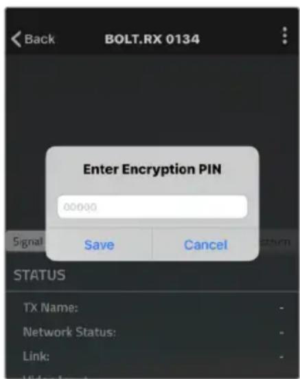
- Enable Bluetooth - Allows the transmitter and receiver to be paired and communicate with the Bolt App
- Use Bluetooth PIN - Enables the use of a PIN for authentication when using the Bolt App (see image)
- Change PIN - Press the Menu joystick towards the right to change the Bluetooth PIN
NOTE: Bluetooth is disabled by default. In order to configure your Bolt 4K devices via the Bolt App, you must first enable Bluetooth.
VIDEO OSD SETTINGS
Choose when to display the On-Screen Display (OSD).
- Never show - Disable OSD
- Show when operating - Hide OSD until it is activated by the joystick.
- Show when no video - Display OSD when there is no video feed; hide OSD when video appears (default).
- Always show - Always display OSD unless temporarily deactivated by the joystick
DISPLAY SETTINGS
Use the Display Settings to control the OLED display operation. By default, the OLED display will invert every 10 minutes. You can set the display to invert every 30 minutes (lengthens the display life), or it can dim or turn off after either 10 minutes or 10 seconds.
• Invert every 30 min
- Dim after 10 min
- Dim every 10 min
- Off after 10 sec
- Dim after 10 sec
• No BurnIn Prevention
RESET ALL SETTINGS
Reset all configurable options to their factory defaults.
DEVICE INFO
Displays the model and serial number.
FIRMWARE VERSIONS
Displays the device's current firmware versions.
BOLT MANAGER
With Bolt Manager, you can configure all of your Bolt 4K devices at once. Available as software for Windows and Mac, Bolt Manager allows you to pair multiple receivers to your transmitter, select frequencies, load 3D LUTs, and perform firmware upgrades.
CONFIGURATION OPTIONS
NOTE: Available configuration settings will differ between Bolt models.
- Pairing - Pair or unpair your devices.
- Settings - Modify the RX/TX name.
- Color Processing - Allows you to apply 3D LUTS to the receiver's video output.
- Upgrade - Update your devices with the latest firmware.
- Status - Displays detailed information about configuration and update statuses.
- About - Displays the software version and License Agreement.
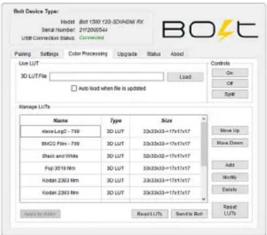
COLOR PROCESSING
Color processing allows users to apply 3D LUTs directly to the receiver's video output or to add, remove, and modify up to 16 LUTs stored in Bolt 4K's memory.
Live LUT - Click Load and browse for a 3D LUT file to apply to the video output. The following file formats are supported:
- .dat (DaVinci Resolve)
• .3dl (Assimilate Scratch) - .cube (DaVinci Resolve)
• .lut (Pomfort LiveGrade) - .mga (Final Cut)
Select Auto load when file is updated. The LUT file will be to re-read and apply LUT files to the video automatically whenever it is updated on your computer.
Manage LUTs - The LUT manager allows you to select up to 16 3D LUT files to store on Bolt. LUTs can be rearranged, renamed, added, and removed using the corresponding buttons.
- Sync - Sync all currently loaded LUTs from the receiver's memory. After syncing, the LUTs will be displayed in the manager window.
- Apply to Video - Apply the selected 3D LUT file to the video output. Once applied, the LUT file can be turned On, Off, or applied to half the display using the Split option.
- Read LUTs - Read Bolt's storage and overwrite the contents of the LUT management window.
- Send to Bolt - Load your LUT presets to your device.
- Reset LUTs - Reset Bolt's storage to default values. A number of pre-defined LUTs are contained in the default configuration.
UPGRADE
Teradek releases firmware updates periodically that add new features, improve performance, and fix vulnerabilities. To update Bolt 4K, you'll need to load a firmware package into Bolt Manager.
Load from Web - If you have an Internet connection, click Load from Web to download the latest firmware package from Teradek's servers.
Load from PC - Click Load from PC if you have already downloaded the firmware package you wish to use. For latest firmware, visit: https://www.teradek.com/pages/downloads#bolt4k
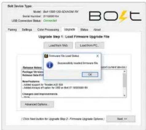
Once the firmware is loaded, and information about the package is displayed, click Next to proceed with the upgrade. You will then be presented with a list of device components and whether or not they are scheduled to be updated, along with two options:
Start Upgrade - Update your Bolt 4K device(s) with the latest firmware version.
Advanced Options - View version details for each component and the firmware upgrade package components. The Advanced screen also allows users to select which components to upgrade.
![BOLT Device Type: Model: Jet 1500 I2G-SDI4CM RX Serial Number: 217200910A USB Connection Status: Connected Loading Settings Color Processing Upgrade Status Send . Load Firmware File and Upgrade Load front press Load front PC... Loaded Firmware File Info Version 4.0.0 ( supports current device ) Loaded Firmware File Content: ✓ Supported Device Module: ● Jet 750 I2G-SDI4CM RX [ for all rights ] ● Jet 1500 I2G-SDI4CM RX [ for all rights ] ● Jet 750 I2G-SDI4CM RX [ for all rights ] ● Jet 1500 I2G-SDI4CM RX [ for all rights ] Components Current Version New Version Upgrade? Progress Controller: 1.14 1.12 Video Processor: 1.3.3 1.3.1 Radio: 7.2.37 7.2.26 Simplify Options... /WNTS - Approaching the Current Version for Radio 1 and 2 download up to a minute! Start Upgrade!](/content/2026/05/1058342/images/eaec4f35abb1e6bba6a07089c3b1a689b92aba5f45ebc187beb8cfb66b3c1766.jpg)
CAN I DOWN-CONVERT FROM 4K TO HD IN ORDER TO DISPLAY VIDEO ON AN HD MONITOR?
Yes. Even if you feed the transmitter a 4K signal, you can output an HD signal from a paired receiver. Output settings are configured on the receiver (see page 20) or the Bolt app.
WILL BOLT 4K WORK WITH MY CURRENT BOLT?
No. Previous generation Bolts cannot communicate with Bolt 4K. Bolt 4K uses a different RF system along with a unique chipset not found in any of the previous generation Bolts.
DOES BOLT 4K SUPPORT SDI METADATA/ANCILLARY DATA PASSTHROUGH?
Bolt 4K supports a limited subset of SDI ancillary data (metadata) from certain cameras. The following data can be passed wirelessly from the transmitter to the receiver:
- Start/stop record flags
- Time code
- File/clip name (RED, ARRI, and Sony cameras)
• Full metadata except for LUTs (ARRI cameras)
The following cameras are capable of transmitting SDI ancillary data, although any camera with time code embedded in the SDI signal should work:
- RED Epic, Scarlet - Supports time code, record start/stop, and file/clip name
- ARRI - Supports full metadata (except for LUTs)
- Canon C300/C500/XF305/XF105 - Supports time code and record start/stop
- Sony VENICE F3/F5/F55 - Supports time code and record start/stop
- Panasonic - Supports time code
THE BOLT APP DOES NOT DISPLAY MY BOLT 4K UNIT.
Ensure that both your Bolt 4K and cellular device have Bluetooth enabled (see page 6). By default, Bluetooth is disabled on your Bolt 4K device until you enable it.
CAN I USE ANY SDI OR HDM I CABLE WITH MY BOLT 4K UNITS?
No. You should make sure that your SDI or HDMI cable is capable of handling 6G or 12G video. If using HDMI cables, it is recommended that you use an HDMI 2.0 compatible cable, and regularly check if your cables are still functional. HDMI cables are extremely delicate and repeated bending can damage the internal wiring to the point where it will no longer send a signal (especially a 4K signal).
HOW MANY RECEIVERS CAN I LINK TO ONE BOLT 4K TRANSMITTER?
You can link up to six Bolt 4K/Bolt 4K LT receivers to any one Bolt 4K/Bolt 4K LT transmitter. On Bolt 4K MAX/Bolt 4K LT MAX transmitters with Broadcast Mode enabled (see page 13), you can link to an unlimited number of Bolt 4K MAX/Bolt 4K LT MAX receivers.
WHAT ARE THE A/C POWER REQUIREMENTS FOR BOLT 4K?
Bolt 4K devices require more power than any of our previous products. When powering Bolt 4K from an A/C outlet, use only the included A/C adapter. This A/C adapter has a higher voltage capacity that meets Bolt 4K's increased power requirements. Lower rated A/C adapters are not supported, and using one will affect Bolt 4K's performance and capabilities.
NOTE: These requirements only apply if you are using an A/C outlet to power on Bolt 4K. Using a compatible battery and accessory cable as a power source will not affect Bolt 4K's performance.
Supported A/C adapters:
- 9V 2.0A (18W)
- 12V 1.5A (18W)
• 12V 3.0A (included with Bolt 4K) - 12V 2.5A (30W)
- 24V 2.5A (60W)
Not supported:
- 12V 1.25A (15W)
CAN I INSTALL BATTERY PLATES ON MY BOLT 4K UNITS MYSELF?
Yes. Recent changes to the device's chassis allows the user to assemble and install battery plates on either the receiver or transmitter. Earlier Bolt 4k units required battery plates to be installed only by a trained technician at a Certified Teradek Repair Center. Contact Teradek to verify if your device's metal work is the latest.
FREQUENCIES BY REGION
NOTE: Pairing the TX and RX is required after a different region is selected.
| Freq Range US (FCC) EU Canada Japan | Australia/New Zealand | |||||||||||
| Bandwidth(MHz) | 40 20 | 40 20 40 20 | 40 20 40 | 40 20 40 | 20 | |||||||
| UNII1(Non DFS) | 5160 5160 | 5160 5160 | 60 | |||||||||
| 5190 | 5180 | 5190 | 5180 | 5190 | 5180 | 5190 | 5180 | 5190 | 5180 | 5190 | 5180 | |
| 5200 5200 | 5200 5200 | 5200 5200 | 5200 | |||||||||
| 5230 | 5220 | 5230 | 5220 | 5230 | 5220 | 5230 | 5220 | 5230 | 5220 | 5230 | 5220 | |
| 5240 5240 | 5240 5240 | 5240 5240 | 5240 | |||||||||
| UNII2(DFS) | 5270 | 5260 | 5270 | 5260 | 5270 | 5260 | 5270 | 5260 | 5270 | 5260 | 5270 | 5260 |
| 5280 5280 | 5280 5280 | 5280 5280 | 5280 | |||||||||
| 5310 | 5300 | 5310 | 5300 | 5310 | 5300 | 5310 | 5300 | 5310 | 5300 | 5310 | 5300 | |
| 5320 5320 | 5320 5320 | 5320 5320 | 5320 | |||||||||
| 5340 | 5340 5340 | |||||||||||
| 5510 | 5500 | 5510 | 5500 | 5510 | 5500 | 5510 | 5500 | 5510 | 5500 | 5510 | 5500 | |
| 5520 5520 | 5520 5520 | 5520 5520 | 5520 | |||||||||
| 5550 | 5540 | 5550 | 5540 | 5550 | 5540 | 5550 | 5540 | 5550 | 5540 | 5550 | 5540 | |
| 5560 5560 | 5560 5560 | 5560 5560 | 5560 | |||||||||
| 5590 | 5580 | 5590 | 5580 | 5590 | 5580 5580 | 5590 | 5580 | 5580 | ||||
| 5600 5600 | 5600 | |||||||||||
| 5630 | 5620 | 5630 | 5620 | 5630 | 5620 | 5640 | 5630 | 5620 | ||||
| 5640 5640 | 5640 | |||||||||||
| 5670/5690/5710 | 5660 | 5670 | 5660 5660 | 5670 5670 | 5660 | 5670 | 5660 | 5660 | ||||
| 5680 5680 | 5690 | 5680 5680 | 5690 | 5680 | ||||||||
| 5700 | 5710 | 5700 5700 | 5700 5700 | 5700 | ||||||||
| 5720 5720 | ||||||||||||
| UNII3(Non DFS) | 5755 | 5745 | 5750 | 5740 | 5755 | 5745 | 5755 | 5745 | ||||
| 5765 5760 | 5765 | 5765 | ||||||||||
| 5795 | 5785 | 5790 | 5780 | 5795 | 5785 | 5795 | 5785 | |||||
| 5805 5800 | 5805 | 5805 | ||||||||||
| 5825 | 5830 | 5820 | 5825 | |||||||||
| 5840 | ||||||||||||
BOLT 4K SYSTEM
BOLT 4K TX BOLT 4K RX
| VIDEO | ||
| Video Inputs | 12G-SDI SMPTE 2082-1 standard/75 Ω,1x HDMI 2.0 Type-A receptacle | N/A |
| Video Outputs | 1x Loopout 12G-SDI SMPTE 2082-1 standard/75 Ω | 2x 12G-SDI SMPTE 2082-1 standard/75 Ω,1x HDMI 2.0 Type-A receptacle |
| SDI Ancillary Data Support | Supports transmitting metadata, timecode, and start/stop flags from certain camera manufacturers. | |
| Color Sampling | SDI: YCbCr 4:2:210-Bit/HDMI: RGB 4:4:4, 8-bit | SDI: YCbCr 4:2:210-Bit/HDMI: RGB 4:4:4, 8-bit |
| Delay (TX to RX) | <0.001sec (without format conversions) | <0.001sec (without format conversions) |
| Supported Resolutions | 4Kp23.98/24/25/29.97/30/50/59.94/601080p23.98/24/25/29.97/30/50/59.94/601080psf23.98/24/25/29.97/301080i50/59.94/60720p50/59.94/60480p59.94/576p50 (via HDMI ports only)480i (NTSC)/576i (PAL) | 4Kp23.98/24/25/29.97/30/50/59.94/601080p 23.98/24/25/29.97/30/50/59.94/601080psf23.98/24/25/29.97/301080i50/59.94/60720p50/59.94/60480p59.94/60 (via HDMI ports only)480i (NTSC)/576i (PAL) |
| Input Cross Conversion | Yes, HDMI to SDI N/A | |
| Output Video Scaling | N/A Yes, Framerate and Resolution Scaling | |
VIDEO PROCESSING
| Video Compression | Visually lossless N/A |
| Test Pattern Generator | N/A Yes |
| Video Format Conversion Support | Yes Yes |
| Spectrum Analyzer | N/A Yes |
Color Correction N/A 17x17x17 3D LUT
AUDIO
| Audio Compression | 48kHz 24-bit PCM 48kHz 24-bit PCM | |
| Audio Input | Embedded SDI/HDMI Audio Input (2 channel) | N/A |
| Audio Output N/A | Embedded SDI/HDMI Audio Input (2 channel) |
BOLT 4K TX BOLT 4K RX
PHYSICAL ATTRIBUTES
Dimensions 5.2" x 3.6" x 1.1" (132 x 91 x 27mm) 4.4" x 5.5" x 1.1" (112 x 139 x 27mm)
| Weight 12.7oz (360g) 15.3oz (434g) | ||
| Construction Milled aluminum (chassis), regulation-compliant PCB | Milled aluminum (chassis), regulation-compliant PCB | |
| INTERFACES | ||
| Configuration Interface | OLED Screen with Menu Joystick Navigation | OLED Screen with Menu Joystick Navigation |
| Switches On/Off Switch On/Off Switch | ||
| Desktop App Bolt Manager app (OSX and Windows) Bolt Manager app (OSX and Windows) | ||
| Mobile App Bolt App (iOS and Android) Bolt App (iOS and Android) | ||
| USB Interface Upgrade via Micro-USB | Upgrade via Micro-USB | |
| Bluetooth Compatibility | Bolt App | Bolt App |
| NETWORK | ||
| Wireless | DFS Frequencies:5.270 ~ 5.670 GHzNon-DFS Frequencies:5.190 ~ 5.230 GHz and 5.755 ~ 5.795 GHz | DFS Frequencies:5.270 ~ 5.670 GHzNon-DFS Frequencies:5.190 ~ 5.230 GHz and 5.755 ~ 5.795 GHz |
| Bluetooth | 2.4 GHz | 2.4 GHz |
| RF Channel Selection | Auto, Manual | Auto, Manual |
| Encryption | AES-256, RSA-1024 key exchange | AES-256, RSA-1024 key exchange |
| RF power | 21 dbm EIRP (max power) | 18 dbm EIRP (max power) |
| Antennas | MAX: 2x External 2dBi antennas,2x H-V antennas750/1500: 4x External 2dBi antennas | MAX: 3x External 2dBi antennas,2x H-V antennas750/1500: 5x External 2dBi antennas |
| Range | MAX: Up to 3000ft (914m) line of sight (5000ft [1524m] with optional Panel Antenna)1500: Up to 1500ft (457m) line of sight750: Up to 750ft (229m) line of sight | |
| Multicast 750/1500: Connect one transmitter to up to 6 receiversMAX (with Broadcast Mode enabled): Connect one transmitter to unlimited receivers | ||
| Noise Rejection | Can coexist with Wi-Fi and 5GHz cordless phones, Can operate up to 6 sets in same location | Can coexist with Wi-Fi and 5GHz cordless phones, Can operate up to 6 sets in same location |
BOLT 4K SYSTEM (cont.)
BOLT 4K TX BOLT 4K RX
POWER
Power Input 2-Pin Circular locking connector 6-28 VDC 2-Pin Circular locking connector 6-28 VDC
| Nominal Power Consumption | 19 Watts 15 Watts | |
| Operating Temperature | 32~104°F (0~40°C) 32~104°F (0~40°C) | |
| GENERAL | ||
| Mountability MAX: | Integrated Gold or V Battery Mount, Multiple mounting options with M3, 3/8" and 1/4-20" holes750/1500: Multiple mounting options with M3, 3/8" and 1/4-20" holes | MAX: Integrated Gold or V Battery Mount, Multiple mounting options with M3, 3/8" and 1/4-20" holes750/1500: Multiple mounting options with M3, 3/8" and 1/4-20" holes |
BOLT PANEL ANTENNA V.4
WIRELESS
| Frequency Range 4.9 - 7.5 GHz |
| Gain 14 and 16dBi |
| Polarization 2x Horizontal and 5x Vertical for polarization. |
| Beam-width deg horizontal 75° |
| Beam-width deg vertical 35° |
| Impedance 50 ohm |
PHYSICAL ATTRIBUTES
| Dimensions | 13.78 x 13.78 x 1.25 in (35 x 35 x 3.18 cm) |
| Weight | 39oz [1111.3g] |
| Construction | UV-protected plastic with aluminum alloy (construction grade) |
| Connectors | RP-SMA |
| Operating temperature | -40~176°F (-40°C to 80°C) |
BOLT 4K LT SYSTEM
BOLT 4K LT - TX BOLT 4K LT - RX
| VIDEO | ||
| Video Inputs | 3G-SDI SMPTE 424M standard/75 Ω(BNC x 1),1x HDMI 1.4b Type-A receptacle | N/A |
| Video Outputs | 3G-SDI SMPTE 424M standard/75 Ω(BNC x 1) | 3G-SDI SMPTE 424M standard/75 Ω(BNC x 1),1x HDMI 1.4b Type-A receptacle |
| SDI Ancillary Data Support | Supports transmitting metadata, timecode, and start/stop flags from most camera manufacturers. Please refer to: https://support.teradek.com/hc/en-us/articles/217446087 | |
| Color Sampling | SDI: YCbCr 4:2:2,10-Bit/HDMI: RGB 4:4:4, 8-bit | SDI: YCbCr 4:2:2,10-Bit/HDMI: RGB 4:4:4, 8-bit |
| Delay (TX to RX) <0.001sec (without format conversions) <0.001sec (without format conversions) | ||
| Supported Resolutions | 4Kp23.98/24/25/29.97/30 (HDMI only)1080p23.98/24/25/29.97/30/50/59.94/601080psf23.98/24/25/29.97/301080i50/59.94/60720p50/59.94/60480p50576p59.94/60480i(NTSC)/576i(PAL) | 4Kp23.98/24/25/29.97/30 (HDMI only)1080p23.98/24/25/29.97/30/50/59.94/601080psf23.98/24/25/29.97/301080i50(59.94/60720p50/59.94/60480p50576p59.94/60480i(NTSC)/576i(PAL) |
| Input Cross Conversion | Yes, HDMI to SDI N/A | |
| Output Video Scaling | N/A No | |
| VIDEO PROCESSING | ||
| Video Compression | Visually lossless N/A | |
| Test Pattern Generator | N/A Yes | |
| Spectrum Analyzer | N/A Yes | |
| AUDIO | ||
| Audio Compression | 48kHz 24-bit PCM 48kHz 24-bit PCM | |
| Audio Input | Embedded SDI/HDMI Audio Input (2 channel) | N/A |
| Audio Output N/A | Embedded SDI/HDMI Audio Input (2 channel) | |
BOLT 4K LT SYSTEM (cont.)
BOLT 4K LT - TX BOLT 4K LT - RX
INTERFACES
| Configuration Interface | OSD with Menu, Joystick Navigation OSD Screen with Menu, Joystick Navigation | |
| Switches | On/Off Switch | On/Off Switch |
| Desktop App Bolt Manager application for OSX & Windows | Bolt Manager application for OSX & Windows | |
| Mobile App Bolt App Bolt App | ||
| USB Interface Upgrade via Micro-USB Upgrade via Micro-USB | ||
| Bluetooth Compatibility | Yes Yes | |
NETWORK
| Wireless DFS Frequencies: | DFS Frequencies: | |
| 5.270 ~ 5.670 GHz | 5.270 ~ 5.670 GHz | |
| Non-DFS Frequencies: | Non-DFS Frequencies: | |
| 5.190 ~ 5.230 GHz and 5.755 ~ 5.795 GHz | 5.190 ~ 5.230 GHz and 5.755 ~ 5.795 GHz | |
| Bluetooth 2.4 GHz 2.4 GHz | ||
| RF Channel Selection | Auto, Manual | Auto, Manual |
| Encryption | AES-256, RSA-1024 key exchange | AES-256, RSA-1024 key exchange |
| RF power 19 dbm | EIRP (2x external 2dBi antennas; <80mW transmit power) | 17 dbm EIRP (1x external 2dBi antenna; <51mW transmit power) |
| Antennas | 2x External 2dBi antennas (included) | 5x External 2dBi antennas (included) |
| Range | MAX: Up to 3000ft (914m) line of sight (5000ft [1524m] with optional Array Antenna)1500: Up to 1500ft (457m) line of sight750: Up to 750ft (229m) line of sight | |
| Multicast | 750/1500: Connect one transmitter to up to 6 receiversMAX (with Broadcast Mode enabled): Connect one transmitter to unlimited receivers | |
| Noise Rejection | Can coexist with Wi-Fi and 5GHz cordless phones, and can operate up to 6 sets in same location | Can coexist with Wi-Fi and 5GHz cordless phones, and can operate up to 6 sets in same location |
| Interoperability | Can transmit wireless video to all ranges of Bolt 4K XT and Bolt 4K LT receivers (limited by shortest range device) | Can receive wireless video from all ranges of Bolt 4K XT and Bolt 4K LT transmitters (limited by shortest range device) |
BOLT 4K LT - TX BOLT 4K LT - RX
PHYSICAL ATTRIBUTES
Dimensions 2.4" x 4.1" x 1.3" (60 x 103 x 33mm) 4.8" x 3.7" x 1" (122 x 94 x 27mm)
Weight 7.3oz (206g) 10.3oz (292g)
Construction Milled aluminum (chassis) and regulation-compliant PCB
Milled aluminum (chassis) and regulation-compliant PCB
POWER
Power Input 2-Pin Circular locking connector 6-28 VDC 2-Pin Circular locking connector 6-28 VDC
| Battery None, optional Sony/Canon dual battery plate | None, optional Gold or V mount battery plate | |
| Nominal Power Consumption | 9 Watts 11 Watts | |
| Operating Temperature | 32~104°F (0~40°C) 32~104°F (0~40°C) | |
| GENERAL | ||
| Mountability Multiple mounting options with M3 and 1/4-20" holes | Multiple mounting options with 3/8"x16 and 1/4-20" holes | |
BOLT 4K MONITOR MODULE (TX/RX)
VIDEO
| Video Input/Output | 1x HDMI 2.0 Type-A receptacle, feeds into Smart 7 HDMI input via block connector |
| Color Sampling | HDMI: RGB 4:4:4, 8-bit |
| Delay (TX to RX) <0.001sec (without format conversions) | |
| Supported Resolutions | 4Kp23.98/24/25/29.97/30 (4K signals will be displayed as 1080p on monitor)1080p23.98/24/25/29.97/30/50/59.94/601080psf23.98/24/25/29.97/301080i50/59.94/60720p50/59.94/60480p50576p59.94/60480i(NTSC)/576i(PAL) |
| Output Video Scaling | No |
| VIDEO PROCESSING | |
| Video Compression | Visually lossless |
| Color Correction | Via Smart7 Monitor (RX module only) |
| AUDIO PROCESSING | |
| Audio Compression | 48kHz 24-bit PCM |
| Audio Output Embedded HDMI Audio Output (2 Channel) into monitor, out on headphones | |
| PHYSICAL ATTRIBUTES | |
| Dimensions 5" x 4.6" x 1" (128 x 118 x 19mm) | |
| Weight Without battery plate: 16.6oz (470g)With battery plate: 18.6oz (526g) | |
| Construction Milled aluminum (chassis) and regulation-compliant PCB | |
| INTERFACES | |
| Configuration Interface | OSD on monitor, Bolt App |
| Switches N/A | |
| Mobile App Bolt App | |
| USB Interface Functionality | Upgrade via Micro-USB |
NETWORK
Wireless DFS Frequencies:
5.270 \~ 5.670 GHz
Non-DFS Frequencies:
5.190 \~ 5.230 GHz and 5.755 \~ 5.795 GHz
RF Channel
Auto, Manual
Selection
Encryption AES-256, RSA-1024 key exchange
RF power 17 dbm EIRP (1x external 2dBi antenna; <51mW transmit power)
Antennas
RX Module: 5x External 2dBi antennas (included)
TX Module: 2x External 2dBi antennas (included)
Range 1500: Up to 1500ft (457m) line of sight
750: Up to 750ft (229m) line of sight
Multicast Can connect one transmitter to up to 6 receivers
Noise Rejection Can coexist with Wi-Fi and 5GHz cordless phones, and can operate up to 6 sets in same location
POWER
Power Input 2-Pin Circular locking connector 6-28 VDC
Battery Gold or V mount battery plate
Nominal Power
10 Watts
Consumption
Operating
32\~104°F (0\~40°C)
Temperature
GENERAL
Mountability Mounts in between SmallHD Smart 7 monitor and battery plate.
PRODUCT INFORMATION
This product is designed to be compliant with rules and regulations in the country it is sold to and therefore is marked as required. These markings signify the countries the device is approved in. Operating the product without regulatory approval is illegal. Any changes or modifications to the product not expressly approved by Teradek could void the user's authority to operate the equipment and its regulatory approvals. Please make sure you use the latest revision of this document which is available at teradek.com.

SAFETY INSTRUCTIONS
- Keep these instructions in a safe and accessible place for future use.
- When operating this equipment, read and follow all the instructions in this manual.
- Do not open the unit.
- Do not block the air ventilation openings, and provide proper ventilation for the units to allow it to cool down during operation.
• Use only accessories/batteries/chargers specified or recommended by Teradek. - When devices are switched ON, keep away at least 20 cm (7.9 in) from your body.
- People with pacemakers should ALWAYS keep the device at the listed distance from their pacemaker when turned ON. Should you have any reason to suspect that interference is taking place, you should turn your device OFF.
- Do not expose to moisture, excessive heat or fire.
- Keep away from water and other liquids.
• Clean with a dry cloth only.
• Unplug this apparatus during lightning storms or when unused for long periods of time.
• To reduce the risk of fire or electric shock, refer servicing to qualified service personnel. - Declared maximum operating temperature: +40°C
- Please avoid electrostatic discharge from the antenna ports for proper operation

WARNING
Bolt 4K devices contain sensitive electronic components that can be damaged by electrostatic discharge (ESD). When handling, care must be taken so that the device is not damaged.
Damage due to inappropriate handling is not covered by the warranty. For complete warranty information, please see the warranty card that arrived with the device, or visit
www.teradek.com/pages/warranty-information.
ANTENNA
The product is provided with an approved antenna. Use only supplied or approved antennas by Teradek. Any changes or modifications to the antenna may void the regulatory approvals obtained for the product.

USING THE AC POWER ADAPTER
- All components must be dry before connecting to an external power source
- Use ONLY a UL/IEC 62368 or UL/IEC 60950-1 2nd revision approved AC/DC power adapter class LPS with electrical output ratings range of 6-28 V DC, 3A, with ambient temperature range of 0°C to 40°C.
- Use of an alternative AC/DC power adapter will invalidate any approvals given to this unit and may be dangerous.

BATTERY
This device is not supplied with batteries. In case a battery is used, please adhere to the following general battery usage guidelines:
• Use batteries with the rated voltage and current characteristics as listed in the manual.
- Use IEC 62133 approved lithium batteries such as the Anton Bauer Digital Battery (Dionic XT 150/Dionic XT 90).
- Verify battery temperature is within the range specified.
- Do not use incompatible/incorrect batteries. Use of an incompatible battery may present a risk of fire, explosion, leakage, or other hazard.
- Severe impact from dropping any battery-operated device on a hard surface could cause the battery to overheat.
RF MODULES
These devices contain the following approved radio modules:
DEVICE DESCRIPTION IC FCC ID
AMN41012 HD Video Transmitter 7680A-AMN41012 VQSAMN41012
AMN42012 HD Video Receiver 7680A-AMN42012 VQSAMN42012
2832 BT Module 4492A-2832 HSW2832
RF EXPOSURE
The product complies with internationally recognized standards covering human exposure to electromagnetic fields from radio devices. To satisfy local RF exposure regulation requirements, the transmitting product must operate with a minimum separation distance of 20 cm or more from a person's body.
FCC RF EXPOSURE STATEMENT
This equipment complies with the FCC RF radiation exposure limits set forth for an uncontrolled environment. This equipment should be installed and operated with a minimum distance of 20 centimeters between the radiator and your body. This transmitter must not be co-located or operating in conjunction with any other antenna or transmitter.
IC RADIATION EXPOSURE STATEMENT
Important Note: Radiation Exposure Statement
This equipment complies with IC radiation exposure limits set forth for an uncontrolled environment. This equipment should be installed and operated with minimum distance 20cm between the radiator and your body.
The radio transmitters 7680A-AMN41012 (HD Transmitter), 7680A-AMN42012 (HD Receiver), and 4492A-2832 (BT Module) have been approved by Industry Canada to operate with the antenna types listed below with the maximum permissible gain indicated. Antenna types not included in this list, having a gain greater than the maximum gain indicated for that type, are strictly prohibited for use with this device. Under Industry Canada regulations, this radio transmitter may only operate using an antenna of a type and maximum (or lesser) gain approved for the transmitter by Industry Canada. To reduce potential radio interference to other users, the antenna type and its gain should be so chosen that the equivalent isotropically radiated power (e.i.r.p.) is not more than that necessary for successful communication.
| MODULES IC | ANTENNA | MAX. PERMISSIBLE GAIN | LOCATION | ANTENNA IMPEDANCE |
| 7680A-AMN41012 | Dipole 2dBi Typical at 5GHz External 50Ω | |||
| 7680A-AMN41012 | Dipole 5dBi Typical at 5GHz External 50Ω | |||
| 7680A-AMN42012 | Dipole 2dBi Typical at 5GHz External 50Ω | |||
| 7680A-AMN42012 | Printed 11dBi typical at 5GHz External 50Ω | |||
| 4492A-2832 | Internal antenna | Internal | ||
UNINTENTIONAL RADIO INTERFERENCE
FCC COMPLIANCE STATEMENT
This equipment has been tested and found to comply with the limits for a Class A digital device, pursuant to Part 15 of the FCC rules. These limits are designed to provide reasonable protection against harmful interference in a residential installation. This equipment generates, uses, and can radiate radio frequency energy, and, if not installed and used in accordance with the instructions, may cause harmful interference to radio communications. However, there is no guarantee that interference will not occur in a particular installation. If this equipment does cause harmful interference to radio or television reception, which can be determined by turning the equipment off and on, the user is encouraged to try to correct the interference by one or more of the following measures:
• Reorient or relocate the receiving antenna.
- Increase the separation between the equipment and the receiver.
- Connect the equipment into an outlet on a circuit different from that to which the receiver is connected.
- Consult the dealer or an experienced radio or television technician for help
This equipment complies with Part 15 of the FCC rules. Operation is subject to the following two conditions:
- This device may not cause harmful interference, and
- This device must accept any interference received, including interference that may cause undesired operation.
IC COMPLIANCE STATEMENT - CAN ICES-3 (A)/NMB-3 (A)
This device complies with the Innovation, Science and Economic Development Canada's licence-exempt RSS(s). Operation is subject to the following two conditions:
- This device may not cause harmful interference, and
- This device must accept any interference received, including interference that may cause undesired operation.
Radio Transmitters (Part 15) - Class A Digital Devices
This device complies with Part 15 of the FCC Rules. Operation is subject to the following two conditions:
- This device may not cause harmful interference, and
- This device must accept any interference received, including interference that may cause undesired operation.
IC STATEMENT
This device complies with RSS-247 of the Industry Canada Rules. Operation is subject to the following two conditions:
- This device may not cause harmful interference, and
- This device must accept any interference received, including interference that may cause undesired operation.
- The device for operation in the band 5150-5250 MHz is only for indoor use to reduce the potential for harmful interference to co-channel mobile satellite systems;
- Users should also be advised that high-power radars are allocated as primary users (i.e. priority users) of the bands 5250-5350 MHz and 5650-5850 MHz and that these radars could cause interference and/or damage to LE-LAN devices.
- The maximum antenna gain permitted for devices in the bands 5250-5350 MHz and 5470-5725 MHz shall be such that the equipment still complies with the e.i.r.p. limit;
- The maximum antenna gain permitted for devices in the band 5725-5850 MHz shall be such that the equipment still complies with the e.i.r.p. limits specified for point-to-point and non point-to-point operation as appropriate.
Avertissement:
EC DECLARATION OF CONFORMITY
This equipment may be operated in all EU countries with the following restrictions:
• 5.15-5.35GHz frequencies for indoor use only

Teradek hereby declares that this Radio Transmitter is in compliance with the essential requirements and other relevant provisions of Directives 2014/53/EU and 2011/65/EU. The full text of the EU DoC is located at: https://support.teradek.com/hc/en-us/articles/233429747-EC-Declaration-r-CE-mark

WASTE ELECTRICAL AND ELECTRONIC EQUIPMENT (WEEE)
English: Waste electrical and electronic equipment should not be disposed of with household waste. Please recycle where facilities exist. Check with your local authority or retailer for recycling advice.
In addition to this Reference Guide, you can find more information on Bolt 4K devices' features and operation by visiting www.teradek.com. If you are unable to find what you need online, please contact Teradek's support staff.
E-mail: support@teradek.com | Phone: (888) 941-2111 ext. 2 (available M-F 7am-6pm PST)
DISCLAIMER
This manual is intended for user information only. Every effort has been made to ensure that the contents within are accurate at the time of printing, and that updates are made in a timely manner. Teradek cannot be held responsible for inaccuracies, typographical errors, or out-of-date information contained within this manual.