
PAWDHWM200A - Water heater PANASONIC - Free user manual and instructions
Find the device manual for free PAWDHWM200A PANASONIC in PDF.

| Product type | Heat pump water heater |
| Brand | Panasonic |
| Model | PAW-DHWM200A |
| Energy efficiency class | A |
| Storage volume | 208 L |
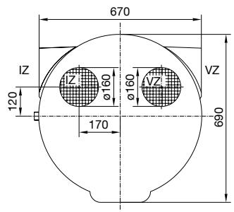
| Dimensions (H x W x D) | 1540 x 670 x 690 mm |
| Weight (net / empty / full) | 149 / 157 / 365 kg |
| Power supply | 230 V / 50 Hz / 16 A |
| Heating power (heat pump) | 2000 W |
| Heating power (electric) | 2 x 1000 W |
| Maximum water temperature | 65 °C (heat pump), 75 °C (electric heating) |
| Refrigerant | R134a, 1100 g |
| Indoor acoustic power level | 59 / 58 dB(A) |
| Moisture protection | IP24 |
| Anti-corrosion protection of the tank | Enameled / Magnesium anode |
| Nominal pressure | 1,0 MPa (10 bar) |
| Main functions | Heat pump, electric heating, Turbo mode, Holiday mode, timer, PV function, anti-legionella, ventilation |
| Maintenance and cleaning | Clean the exterior with a mild detergent; inspection of the Mg anode every 36 months by an approved specialist |
| Spare parts and repairability | Heating elements, anode, fan, compressor, sensors, etc. (exploded view list in the manual) |
| General information | Installation by qualified professional; safety valve mandatory; recommended temperature 45-55 °C |
Frequently Asked Questions - PAWDHWM200A PANASONIC
User questions about PAWDHWM200A PANASONIC
0 question about this device. Answer the ones you know or ask your own.
Ask a new question about this device
Download the instructions for your Water heater in PDF format for free! Find your manual PAWDHWM200A - PANASONIC and take your electronic device back in hand. On this page are published all the documents necessary for the use of your device. PAWDHWM200A by PANASONIC.
USER MANUAL PAWDHWM200A PANASONIC
EiayetaiTov aiohntnpa oTo oAoIyva kai oTepeWote to:
Eav ykataotae tov aohtnpa 0ia uynlptn 0uae npoatnc 0 avtanokpi tio yprjyopa, n peiooc, eitoupyiac nct avtlaic kukloopipac, 0 evai mikpoptn, ndiaopap maetaku c tnc 0epokpaiaac tou vpu otn deqauvi kai tou meau oepuvanc meta tvnevepyonoin Tou 0epuotatn 0ivai uynlotepn, kai kat aovteia n nootnta kai n 0epokpaiaou tou ovo vpu oto doxio 0eivai xamnlotpqn.
Eav o aiθntnpac yka thotatai eia kai npertn thean, ta evai n ppioboc aeoupyiac tnc avlaic kukloopipac meyautepn, n diaopap aetau tnc thepokpaia c Tou thepavikou moukai n etakolouon thepokpasia tou vepou ot n deqevn ta evai xauhntepn, n thepokpasia kai kat auventia n noootra tou vepou stov thepavnpa 0eivai nioevcw uynlntepn.
TOIPOETHSHTHEAEMENHANOOHKEYHZEYOYNEPOYMETHNANTIAOEPMOTHTA
ZeTo Vepo TnC DExaevnc aOnrKeuucn eTnV avTia 0epoTnTcA npoei va xpnaiouonioe iOn Ieoupyia epiBaalovtiok n Kaobnyouevo aepa.
Tia va anopexuxTei npvtikniiean oTo Ktiipio, npentie oXwpoc Eeyxóveva v povtfooue yia tnV npoxn fpeokou aepa. O tIbmuTrc puOmuoc avtaaync
aepa yia Tnv Ptolukatoikia evai 0,5.Auto onmaivei ot n ouvloki nooTnta tou aepa st Ktiipio va avtaalaoetai kKe 2 wpc.
AEITOYPTIA ME AEPA TOY IEPIBAANTIKOY XOPOY
M T N V K L I M A K W O N T W V A E P O D U V A M I K O X A P A K T N P I O T I K W O A T O T N C X A M I O T E P E C M E X P I T U S I A I O T E P E C, E V I O X U E T A I K A O T O P U B O C T O U O U T N M A T O C. M E T A E U T W A E P O D U V A M I K W O X A P A K T N P I O T I K W O 80% KAI 100%, EIVAI N T P E I O X N, OIIOU EVIAI AVTIAI NIN N A U E N O N TOU OPOBou.
Dounéπéδou napoxic unnpεoiwv
The appliance may be used by children aged 8 and older and persons with physical, sensory or mental disabilities or lacking experience or knowledge, if they are under supervision or taught about safe use of the appliance and if they are aware of the potential dangers.

Children should not play with the appliance.

Children should not clean or maintain the appliance without supervision.

In time of transport, the heat pump must be placed in the upright position and can be leant up to 35^ in all directions upon exception.

The heat pump must not be placed in a closed space, containing corrosive and explosive materials.

The connection of the heat pump to the power supply must be performed in accordance with the standards for electrical installations. An appliance for the disconnection from the electrical network must be installed between the heat pump and the electrical network in accordance with the national installation regulations.

In avoidance of aggregate damage the heat pump must not operate without water in the tank.

The installation should be performed in accordance with the valid regulations and the instructions of the manufacturer. It should be performed by a professionally trained installation expert.

It is obligatory to install a safety valve with a rated pressure of 1 Mpa (10 bar) on the inlet pipe of the heat pump of the closed pressure system to prevent the elevation of pressure in the tank by more than 0.1 MPa (1 bar) above the rated pressure.

Water may drip from the outlet opening of the safety valve, so the outlet opening should be set to atmospheric pressure.

The outlet of the safety valve should be installed facing downwards and in a non-freezing area.

To ensure proper functioning of the safety valve, the user should perform regular controls to remove limescale and make sure the safety valve is not blocked.

Do not install a stop valve between the heat pump and the safety valve, because it will impair the pressure protection of the storage tank!

Elements of the electronic control unit are under voltage even after the heat pump has been switched off (9).

The storage tank is protected in case of failure of the operating thermostat with an additional thermal cut-out. In case of thermostat failure water in the storage tank may reach the temperature of up to 130^ in accordance with safety standards. The possibility of such temperature overload should be taken into consideration in the execution of plumbing.

Should you choose to disconnect the power, the storage tank should be drained thoroughly before the onset of freezing conditions.

Water from the storage tank is drained through the inlet pipe of the tank. For this purpose, a special fitting (T-fitting) with an outlet valve must be mounted between the safety valve and the inlet pipe.

Please, do not try to fix any defects of the heat pump on your own. Call the nearest authorised service provider.

Connection of the heat pump to the same pipeline whit the kitchen vent, the ventilation system of smaller apartments is not allowed.

The decline in temperature of an additional heating source and the enabled water circulation via the heat exchanger can cause an uncontrolled removal of heat from the water tank. When connecting to other heating sources it is necessary to ensure proper temperature regulation of the additional heating source.

When connecting to sources of solar energy as an external heating source the aggregate of the heat pump must be disconnected. The combination of both heating systems can lead to overheating of water and consequently to excessive pressure.

Circulation leads to additional heat loss in the water tank.

Our products incorporate components that are both environmentally safe and harmless to health, so they can be disassembled as easily as possible and recycled once they reach their final life stage.
Recycling of materials reduces the quantity of waste and the need for production of raw materials (e.g. metals) which requires a substantial amount of energy and causes release of harmful substances. Recycling procedures reduce the consumption of natural resources, as the waste parts made of plastic and metal can be returned to various production processes.
For more information on waste disposal, please visit your waste collection centre or the store where the product was purchased.
Dear buyer, thank you for purchasing our product.
PRIOR TO THE INSTALLATION AND FIRST USE OF THE HOT WATER STORAGE TANK WITH THE HEAT PUMP, PLEASE READ THESE INSTRUCTIONS CAREFULLY.
This storage tank has been manufactured in compliance with the relevant Standards, which allow the manufacturer the use of the CE sign. The technical characteristics of the product are listed on the label attached to the protective cover.
The connection of the storage tank with the heat pump to the plumbing and power networks must be carried out by qualified staff only. All repairs and maintenance work in the interior of the storage tank, as well as limestone removal or testing or replacement of the corrosion protection anode, may only be carried out by an approved maintenance service provider. Be especially careful when following instructions for potential errors and safe use of the heat pump.
Store this booklet for times of doubt upon the functioning or maintenance.
The installation manual is available on our webpage www.aircon.panasonic.eu or the webpages per country in the service and support section.
Authorised maintenance personnel are available for occasional maintenance. They will help you with their vast experience.
The hot water storage tank is designed in a manner which allows using the following heating sources:
- Central heating storage,
Solar power,
Electric heater.
USE
This unit is designed for production of sanitary water in households and at premises where daily consumption of hot water (50 °C) does not exceed 400 l to 700 l. The set temperature should suffice actual needs. Recommended temperature settings are between 45 and 55^ . Higher temperatures are not recommended as they reduce the efficiency (COP) and extend the time of heating or increase the number of operating hours. Because during its operation the heat pump cools its surroundings, the usefulness of the heat pump is doubled (heating water - cooling air). The operation of the heat pump is completely automatic.
The appliance must be connected to water supply mains and to the power supply grid. The air intake and air exhaust may also be provided by designing the inlet and outlet drain from and to the adjacent room. We recommend leaving enough space between the floor and unit as to provide easy access to the Mg anode (for maintenance or replacement purposes - Fig. 4). The heat pump may not be used for purposes other than those defined in these Instructions. The unit is not designed for industrial use or use in rooms where corrosive or explosive substances are present.
The manufacturer shall not assume any liability for damages caused by incorrect installation or misuse that are not in compliance with the Instructions for installation and use.
The instructions for use are a component and important part of this product and must be delivered to the customer. Read the warnings carefully, as they contain important directions related to safety during operation, use and maintenance.
Keep these Instructions for later use.
The marking of the heat pump is stated on the nameplate located on the bottom side of the unit, between both inlet pipes for sanitary water.
Once the packaging is removed, check the contents. When in doubt, contact your dealer. Never let children play with the packaging parts (clamping, plastic bags, expanded polystyrol, etc.) - potential risk. Make sure to remove and dispose of the packaging safely and in an environmentally friendly way.
The appliance is not intended for use in closed space, containing corrosive and explosive materials.
In time of transport, the heat pump must be placed in the upright position and can be leant up to 35^ in all directions upon exception. Please make sure, no damage of the casing and other vital parts of the appliance occurs during transport.
STORAGE AND TRANSPORT
Store the heat pump in an upright position, in a clean and dry place.
| Type | PAW-DHWM200A | PAW-DHWM300A | PAW-DHWM300AE | |
| Use profile | L | XL | XL | |
| Energy efficiency class | A | A | A | |
| Energy efficiency of water heating (wwh)1) | % | 124 | 135,6 | 134,4 |
| Annual electrical energy consumption1) | kWh | 821 | 1235 | 1247 |
| Daily electrical energy consumption1) | kWh | 3,891 | 5,722 | 5,785 |
| Set thermostat temperature | °C | 55 | 55 | 55 |
| Level of indoor sound power3) | dB (A) | 59/58 | 59/58 | 59/58 |
| Smart value | 0 | 0 | 0 | |
| Storage volume | I | 208,0 | 295,0 | 276,0 |
| Mixed water at 40 °C V402) | I | 265 | 395 | 368 |
| Potential safety measures(assembly, installation, maintenance) | Compulsory use of a safety valve with the pressure connection. | |||
| Technical characteristics | ||||
| Heating time A15 / W10-55 24) | h:min | 5:17 | 8:05 | 8:00 |
| Heating time A7 / W10-55 5) | h:min | 6:10 | 9:40 | 9:39 |
| Energy consumption in the selected cycle of emissions A15 / W10-554) | kWh | 3,95 | 5,65 | 5,75 |
| Energy consumption in the selected cycle of emissions A7 / W10-555) | kWh | 4,05 | 5,77 | 5,96 |
| \( COP_{DHW} \) A15/W10-554) | 3,07 | 3,39 | 3,38 | |
| \( COP_{DHW} \) A7/W10-555) | 3,00 | 3,33 | 3,30 | |
| Power in standby mode5) | W | 28 | 18 | 20 |
| Refrigerating agent | R134a | R134a | R134a | |
| Quantity of refrigerant | g | 1100 | 1100 | 1100 |
| Operation area | °C | -7 ÷ 35 | -7 ÷ 35 | -7 ÷ 35 |
| Area of airflow | m3/h | 220-450 | 220-450 | 220-450 |
| Max acceptable pressure drop in the pipeline(volumetric flow rate of a at 330 m3/h) (60%) | Pa | 100 | 100 | 100 |
| Electrical characteristics | ||||
| Specified power of the compressor | W | 490 | 490 | 490 |
| Heater power | W | 2000 | 2000 | 2000 |
| Maximum connection power without heater/with heater | W | 490/2490 | 490/2490 | 490/2490 |
| Voltage | V/Hz | 230/50 | 230/50 | 230/50 |
| Electrical protection | A | 16 | 16 | 16 |
| Moisture protection | IP24 | IP24 | IP24 | |
| Water tank | ||||
| Anti-corrosion protection of tank | Enamelled / Mg Anode | |||
| Nominal pressure | MPa | 1,0 | 1,0 | 1,0 |
| The highest water temperature heat pump | °C | 65 | 65 | 65 |
| The highest water temperature electrical heater | °C | 75 | 75 | 75 |
| Connection measurements | ||||
| Total height | mm | 1540 | 1960 | 1960 |
| Width | mm | 670 | 670 | 670 |
| Depth | mm | 690 | 690 | 690 |
| Inlet/outlet water connections | G1 | G1 | G1 | |
| Inlet/outlet air connection dimensions | mm | Ø160 | Ø160 | Ø160 |
| Heating area PT - bottom | m2 | / | / | 2,7 |
| Heating area PT - top | m2 | / | / | / |
| Exchanger connectors | - | - | G1 | |
| Weight/Filled with water | kg | 149/157/365 | 164/172/459 | 207/215/480 |
| The temperature of the heating medium in the heat exchanger | °C | / | / | 5 ÷ 95 |
| Transport data | ||||
| Packaging | mm | 800x800x1765 | 800x800x2155 | 800x800x2155 |
1) directive 812/2013, 814/2013, EN16147:2011
2) in accordance with EN16147:2011
3) in accordance with EN12102:2013 (60% fan speed - outside air/40% fan speed - ambient air)
4) inlet air temperature 15^ 74% humidity, water temperature between 10 and 55^ in accordance with EN16147:2011
5) inlet air temperature 7^ 89% humidity, water temperature between 10 and 55^ in accordance with EN16147:2011
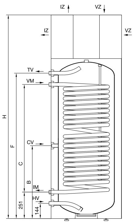
LEGEND
PT Heat exchanger
HV Cold water inlet (H - blue rosette)
IM Outlet PT (black rosette)
CV Circulation pipeline (black rosette)
VM Inlet PT (black rosette)
TV Hot water outlet (T-red rosette)
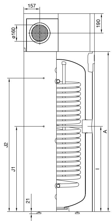
J1 Sensor pipe
J2 Sensor pipe
VZ Air inlet
1Z Air outlet
Figure 1: Connection and installation tank dimensions [mm]
| PAW-DHWM200A | PAW-DHWM300A | PAW-DHWM300AE | |
| A (mm) | 1170 | 1560 | 1560 |
| B (mm) | 580 | 690 | 690 |
| C (mm) | / | / | 1020 |
| F (mm) | 975 | 1375 | 1375 |
| H (mm) | 1540 | 1930 | 1930 |
| I (mm) | 615 | 840 | 840 |
| J1 (mm) | / | / | 790 |
| J2 (mm) | / | / | 1300 |
| HV | G1 | G1 | G 1 |
| IM | / | / | G 1 |
| CV | G3/4 | G3/4 | G3/4 |
| VM | / | / | G 1 |
| TV | G 1 | G 1 | G 1 |
OTHER HEATING SOURCES - SENSOR INSTALLATION
On the left side of the hot water storage tank are two openings (J1, J2), where the sensors for the control system of the connection of the hot water tank to other heating sources. The maximum diameter of the probe is 8 mm. The length of the sensor tube is 180 mm. Insert the sensor into the tube and attach it:
- if you install the sensor into a higher position, the thermostat will respond faster, the operation period of the circulation pump will be shorter, the difference between the water temperature in the storage tank and the temperature of the heating source after the shutdown of the thermostat will be higher. Consequently, the quantity and the temperature of hot water in the storage tank will be lower.
- if you install the sensor in a lower position, the operation period of the circulation pump will be longer, the difference between the water temperature in the storage tank and the temperature of the heating source after the shutdown of the thermostat will be lower. Consequently, the quantity and the temperature of hot water in the storage tank will be higher.
INSTALLATION OF THE HOT WATER STORAGE TANK WITH THE HEAT PUMP
The heat pump can be used using the ambient air or air from other premises.
To prevent pressure depression in the building, fresh air must be regularly supplied to the premises. The desired rate of air exchange for a residential building is 0.5. This means that the entire quantity of air in the building is exchanged every two hours.
In this type of operation, the device heats domestic water using only the amount of energy generated by the air from the room where the device is installed. The heat pump must be installed in a dry, frost-free room, possibly in the vicinity of other heating sources with the recommended temperature ranging between 7 and 35^ and a minimum volume of 20m^3 .
For optimal performance of the heat pump, we recommend a sufficiently large and well ventilated room with the temperature ranging between 15^ and 25^ .
When selecting a place for installation, particular attention should be paid that the selected air intake location is dust free, because dust has adverse effects on the heat pump performance. Because pressure drop does not occur with the ambient air operation it is reasonable to reduce the fan speed from factory settings of 60% to 40% to reduce noise (See further chapters).
There are several inlet and outlet openings possible with this model (See figure).
Elbows are more suitable for ambient air operation and must be installed on the heat pump and turned so that they prevent the mixing of air.
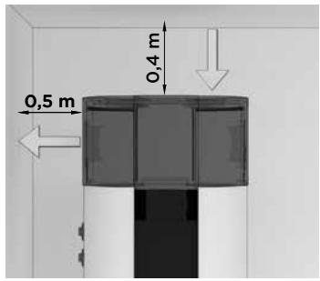
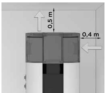
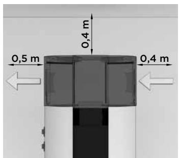
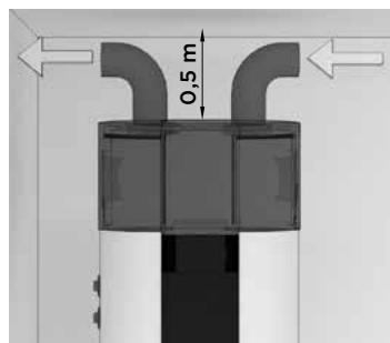
Figure 2: Options of inlet and outlet openings
OPERATION USING AIR FROM OTHER PREMISES
In this type of operation, the heat pump uses air from other premises via a pipeline system. It is advisable to insulate the pipeline system to prevent the formation of condensate. In case of using air from outside, the external part must be covered so as to prevent the intrusion of dust or snow into the appliance.
To make sure the operation of the pump is effective at all times, you can install dampers to take air from the premises and then return it either to the premises or outside. The temperature of the taken air must correspond with the standards of the specification of the product (see table with technical characteristics).
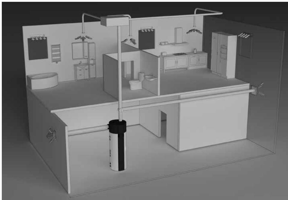
Figure 3: Operation using air from other premises
DETERMINING PRESSURE LOSS IN THE AIR INLET AND OUTLET PIPELINE SYSTEM
The heat pump offers various installation options of connection of the air inlet and outlet pipelines. We recommend the connection options, which enable the simplest installation of the appliance to the pipeline system. When designing the pipeline system for air inlet and outlet to and from the heat pump it is essential to consider the aerodynamic characteristics of the heat pump fan, where the static pressure loss occurs.
The aerodynamic characteristics are displayed in a graph as a pressure drop in relation to airflow. The operating point of the heat pump fan is at 100Pa of static pressure or at airflow of 330~m^3 . Working drop of static pressure in an air pipeline of heat pumps is considered p = 100Pa . If the calculations show higher pressure drops, the fan speed can be increased. The increase of the fan speed is effective up to 80% . The airflow does not increase above this level, therefore we advise against further increase for it will only cause higher levels of noise.
The diagram shows the following areas:
- High-efficiency area - area of high airflow rates (over 300m^3 ) requires lower pressure drops (pipeline free or short pipeline) and fan settings to 60% or 80%.
- Middle-efficiency area - area of middle airflow rates (between 200 and 300m^3/h ), 40% fan settings, minimum pressure drop, 60% or 80% of settings and pressure drops between 50 and 300Pa .
- Expanded area for higher ambient temperatures - a wider range of settings and high pressure drops. These settings may be in use only with air temperature over 20^ , otherwise an efficiency decline occurs.
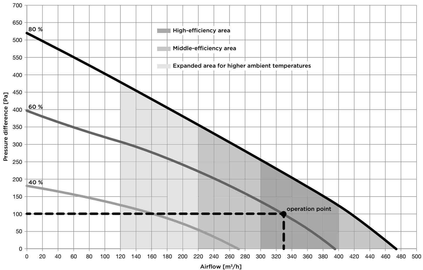
Figure 4: Aerodynamic characteristics of heat pump fan
Values of total static pressure drop are calculated by adding up pressure drops of each individual element, installed in the air pipeline system. Values of pressure drops of each individual element (diameter 150 mm) are presented in the following table.
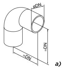
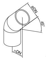
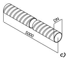
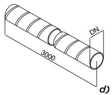
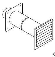
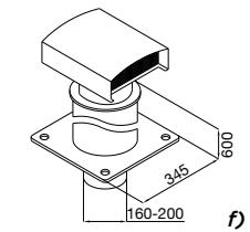
Figure 5: Diagram of basic elements of the air inlet and outlet pipeline system
Element types and their pressure drops.
| Element type | Values of pressure drops of each individual element |
| a) Bend 90° | 5 Pa |
| b) Bend 45° | 3 Pa |
| c) Flexible hose | 5 Pa/m |
| d) Spiro hose | 3 Pa/m |
| e) Suction grille | 25 Pa |
| f) Top exhaust air outlet | 10 Pa |
The calculations of the pressure values are informative. More accurate calculations of airflows require more detailed characteristics of individual elements or information from the developer. After the installation we recommend measurements of the airflow in the pipeline system. Values of total static pressure drop are calculated by adding up pressure drops of each individual element, installed in the air pipeline system. Recommended nominal operation is at the sum total of ca. 100 Pa. In case of airflow decrease COP drops.
Calculation example
| Number of elements | Δp (Pa) | ΣΔp (Pa) | |
| Bend 90° | 4 | 5 | 20 |
| Flexible hose | 8 | 5 Pa/m | 35 |
| Suction grille | 1 | 25 | 25 |
| Top exhaust air outlet | 1 | 10 | 10 |
| Sum total | 100 |

Connection of the heat pump to the same pipeline whit the kitchen vent, the ventilation system of smaller apartments is not allowed.
During operation of the heat pump condensate forms in the aggregate. The condensate should be drained to the sewage system via flexible tube 16mm on the rear side of the heat pump. The quantity of condensate depends on air temperature and humidity or air.
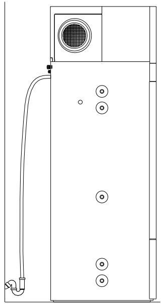
Figure 6: Connection to water supply mains - condensate outlet
To reduce noise and vibrations of the installed fan take the following steps to prevent the noise and vibrations to be transmitted through walls into rooms, where it would be disturbing (bedrooms, restrooms):
- install flexible connectors for hydraulic jacks
- install flexible pipes for air inlet and outlet
- isolate the vibrations for wall transmitters
- provide silencers for air inlet and outlet
- air inlet and outlet pipes attach with vibration silencers
- predict isolation of vibrations via flor
- use support elements.
CONNECTION TO WATER SUPPLY MAINS
Connect the water pipeline system according to the attachment signs from the previous chapter.
Installing a safety valve is mandatory in order to assure safe operation. The valve prevents an increase of the pressure in the boiler by any more than 0.1MPa (1 bar) above the nominal pressure. The outflow nozzle on the safety valve must have an outlet into the atmosphere. To assure correct operation of the safety valve, check the valve regularly and, if necessary, remove the limescale and check that the safety valve is not blocked. When checking the valve, push the lever or unscrew the nut of the valve (depending on the type of the valve) and open the drain from the safety valve. Water must flow from the valve nozzle, showing that the valve operation is faultless. During the heating of water, the water pressure in the hot water tank is increased up to the level present in the safety valve. Since the system prevents backflow of water into the water supply mains, water may be dripping from the outlet opening on the safety valve. The dripping water may be drained via trap into the drains; the trap is mounted under the safety valve. The outlet pipe, which is mounted under the safety valve, must be directed downwards, in a place with a temperature above freezing.
If the installation does not allow draining of the water from the safety valve into the drains, dripping can be avoided by installing an expansion vessel onto the heat pump inlet pipe. The volume of the expansion vessel must be ca. 5% of the hot water tank volume.
The heat pump is designed for connection to indoor water supply mains without using the relief valve if the pressure in the supply mains is lower than prescribed on the appliance. If the pressure is higher, a relief valve needs to be installed so as to provide that the pressure at the inlet to the hot water tank does not exceed the nominal pressure.
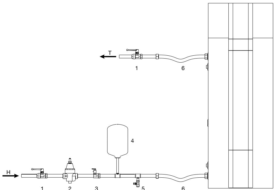
Figure 7: Closed pressure system
LEGEND
1 Stop valve
2 Relief valve
3 Safety non-return valve
4 Expansion tank
5 Drain valve
6 Flexible hose
H Cold water
T Hot water
In avoidance of aggregate damage the heat pump must not operate without water in the tank.
CONNECTION TO OTHER HEATING SOURCES
Hot water storage tank with the heat pump enables water heating via one or two heat exchangers with different energy sources (e.g. central heating, solar energy ...).
Connection options to different heating sources are shown below.
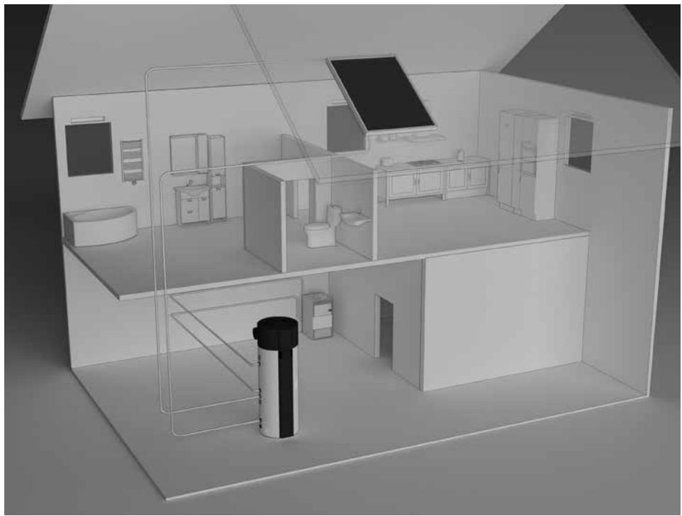
Figure 8: Connecting to other heating sources


With a temperature decline of an additional heating source and with an enabled water circulation through the heat exchanger proper temperature control of the additional source must be ensured.
If the additional energy source is solar power, the operation of the aggregate of the heat pump must be shut off. The combination of two heating sources can lead to overheating of the hot water and thus to excessive pressures.
The circulation pipeline causes additional temperature decline in the hot water storage tank.
CONNECTION TO THE POWER SUPPLY NETWORK
In order to connect the hot water storage tank with the heat pump to the power supply network first install an electrical socket suitable for the current load of 16 A.
Connecting the heat pump to the power supply network must take place in accordance with the standards for electric appliances.
To comply with the national installation regulations, an all poles disconnect switch must be installed between the heat pump and the power supply network.
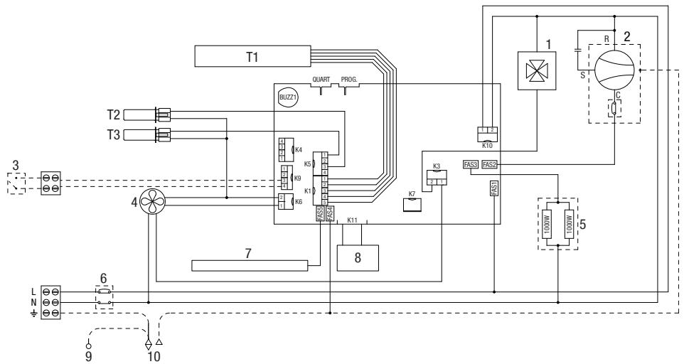
Figure 9: Connection to the power supply network
LEGEND
T1 Bar with sensors
T2 Evaporator - temp. sensor
T3 Air temperature sensor
1 4-way valve
2 Compressor
3 PV function
4 Fan
5 Electric heating element (2 x 1000W)
6 Thermal cut-out
7 Magnesium anode
8 LCD touch screen
9 Housing - ground (in case of a metal casing)
10 Boiler - ground
The heat pump can be operated using an LCD touch screen (Fig. 10). If you press anywhere on the screen, the screen lights up. When the screen is lit up, the operation fields are active.
When the heat pump is connected to the water and power supply mains and the boiler is filled with water, the heat pump is ready to be used. The heat pump heats the water in the range 10^ - 65^ . From 65^ - 75^ the water is heated by electrical heaters.
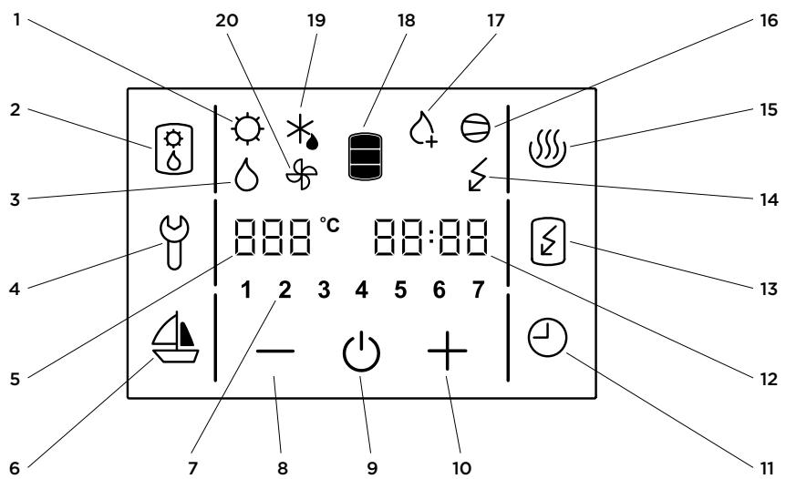
Figure 10: Operation display
LEGEND
1 Signalization of the operation of solar collectors
2 Alternative source of heating/turned on
3 Signalization of the backup operation
4 Indication, overview of operation errors, entrance into the service menu
5 Display and setup of temperature in ^ C
6 Start and setup of the VACATION programme
7 Day of the week (1..Monday,.,7..Sunday)
8 Reducing the value
9 Heat pump on/off switch
10 Increasing the value
11 TIMER start and setup
12 Time setup and display
13 Start-up of quick heating "TURBO"
14 Indicator of the heating element operation
15 Start-up of heating to the maximum temperature level
16 Signalization of compressor operation
17 Signalization of anti-legionella programme operation
18 Warm water quantity display
19 Signalization of defrosting
20 Signalization of fan operation
Starting/stopping the heat pump
- Starting/stopping the heat pump
When the appliance is switched on, the fan starts first and operates for one minute (symbol no. 20 is displayed). If the temperature of inlet air is appropriate, the controlling unit switches on the compressor and the heat pump operates in normal mode (symbols 16 and 20 are displayed). The heat pump is on, the screen remains unlit and inactive.
In 60 seconds after the last touch of the screen, the illumination and activity of the screen are turned off, but that does not affect the operation of the heat pump. Pressing anywhere on the screen re-activates the screen and its illumination.
If trying to start up at a lower temperature, please see chapter "Operation at lower temperatures".
- By holding field no. 9, the heat pump is switched off.
The appliance stops functioning and the only field visible on the screen is field no. 9. (If you switch off the heat pump for a longer period of time, the water must be drained from the pump if there is any danger of freezing).
Power failure protection
In case of power failure, the settings remain stored for up to 23 hours.
After restarting, the heat pump operates in the same mode it was operating in before the power failure.
Operation at lower temperatures
When the appliance is switched on, the fan starts first and operates for one minute (symbol no. 20 is displayed). If the temperature of inlet air is lower than -7^ , the fan is turned off. Domestic water is heated with heaters. The heat pump operates in the reserve mode (symbol no. 14 is displayed). The possibility of switching to normal mode is checked every 2 hours by switching on the fan for one minute. If the temperature of inlet air is higher than -7^ , the heat pump switches to normal mode of operation (symbols 16 and 20 are displayed). The heaters switch off. The heat pump is on, the screen remains unlit and inactive.
At lower air temperatures, the evaporator defrosting cycle is started if necessary. Symbol no. 19 is displayed on the screen. The fields 2, 4, 6, 11, 13 and 15 remain inactive. Defrosting takes place until the conditions for normal operation of the heat pump are achieved.
After successful defrosting, the heat pump returns to normal operation (symbols 16 and 20 are displayed).
If defrosting is unsuccessful, the controlling unit displays an error message. Field no. 4 starts flashing, accompanied by warning beeps. By pressing field no. 4 the warning beeps can be turned off. Error code E247 appears in field no. 12 and the pump switches automatically to heating with electric heaters. The screen displays symbol no. 14. The error code can be deleted at any time by pressing field no. 4. Field no. 12 resumes to displaying time.
Setting the clock and day of the week
- Hold field no. 12, until field no. 7 shows a flashing number of the day of the week.
- By pressing + or - you can set the number of the day of the week (1 - Monday, ..., 7 - Sunday).
- Press field no. 12 again (flashing hour setting is displayed).
- By pressing + or - set the hour (by holding + or - you can speed up the setting).
- Press field no. 12 again.
- Flashing minute setting is displayed.
- By pressing + or - set the minutes (by holding + or - you can speed up the setting).
- The setting is stored when you press field no. 12, or when the field stops flashing.
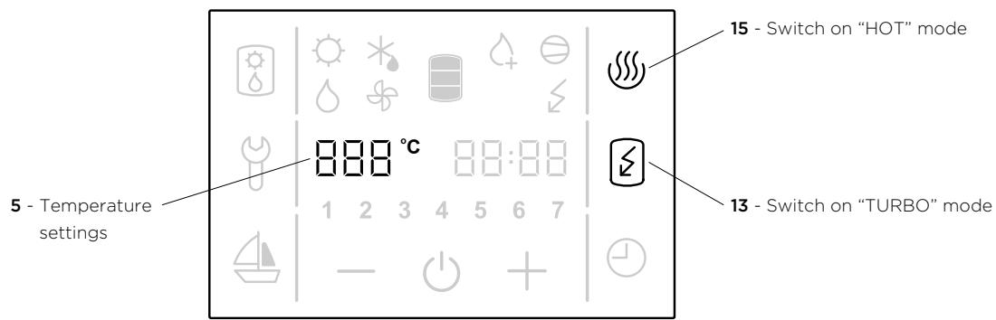
Figure 11: Temperature settings, switch on "TURBO" and "HOT" mode
Setting the temperature
- Press field no. 5 (the set temperature starts blinking).
- By pressing + or - you can change the temperature setting from 10^ to 75^ (preset to economic temperature of 55^ ).
- The setting is stored by pressing field no. 5 again, or when field no. 5 stops flashing. After a few seconds, the display shows the actual temperature. The set temperature should suffice actual needs. Recommended temperature settings are between 45 and 55^ . Higher temperatures are not recommended as they reduce the efficiency (COP) and extend the time of heating or increase the number of operating hours.
- In case of power failure, the last stored value is restored.
Switching on the "TURBO" mode
- If you need more warm water than the heat pump can heat up in a short period of time, press field no. 13 (switches on the "TURBO" mode). The heat pump and heater work simultaneously. The screen shows symbols no. 14, 16 in 20. When the temperature reaches 55^ C the heat pump returns to the mode used before the "TURBO" mode.
Switching on the "HOT" mode
- If you want to heat the water to the maximum temperature of 75^ , press field no. 15. The heat pump will heat water to 55^ . The screen displays symbols no. 16 in 20. When the temperature in the boiler reaches 55^ the electric heater turns on to heat the temperature up to 75^ . The screen displays the symbol no. 14. When the temperature reaches 75^ the heat pump returns to the mode used before the "HOT" mode.
Display of the quantity of water in the heat pump
The display shows the symbol 18:
- no warm water
- low quantity of warm water
- high quantity of warm water
Setting the vacation mode
In the vacation mode, you can set the number of days (maximally 100), when the heat pump shall maintain the minimal temperature of water (approximately 10^ ).
- Hold field no. 6 for a while (fields 5 and 6 start to flash).
- By pressing fields + or - you can set the number of vacation days shown in field no. 5.
- By pressing field no. 6 again, or when field no. 6 stops flashing, the set number of days is stored.
- If you set the value to 0, then the heat pump will resume its normal operating mode after confirming the setting, and illumination of field no. 6 will turn off.
After the set number of days has elapsed, the heat pump returns to the normal mode and illumination of field no. 6 turns off.
Setting the TIMER mode
In the TIMER operating mode, you can set the times when the heat pump will start and stop. For each timer combination you can set up to three time periods in which the heat pump will not heat the water.
a) Setting the timer combinations
- Hold field no. 11 for a while (fields 7 and 11 start to flash).
-
By pressing fields + or - choose among three timer modes of operation:
-
Timer mode of operation of the heat pump for the entire week (numbers 1-7 flash in field no. 7),
- Timer mode of operation of the heat pump for Monday to Friday and Saturday to Sunday
(numbers 1-5 and then 6 and 7 flash in field no. 7),
- Timer mode of operation of the heat pump for each day at a time (individual numbers 1-7 flash in field no. 7).
To set the time, press field no. 12.
- On the field no. 5, the text 1OF appears and field no. 12 starts to blink.
- By pressing fields + or - set the time of shutdown.
- Press field no. 12 again.
- On the field no. 5, the text 1ON appears and field no. 12 starts to blink.
- By pressing fields + or - set the time of start-up.
- By pressing field no. 12 again, you can use the above procedure to set the second and third period.
- By pressing field no. 12 again, or when field no. 6 stops flashing the set number of days is stored. Again, press field no. 12.
b) Activation, deactivation of timer
- By pressing field no. 11, you can activate the set timer mode.
- The heat pump heats the water in the ON periods (to the set temperature) and in the OFF periods, it does not heat the water.
- By pressing field no. 11 again, you can deactivate the set time mode of operation.
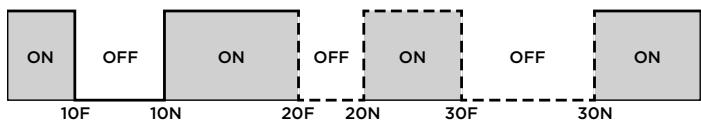
Figure 12: Time period
Fan settings
When the pressure drop is defined you select fan mode. It determines the fan speed.
Choose fan mode with the help of the graph (Figure 12), displaying the aerodynamic characteristics of the fan in relation to the airflow and pressure drop in the air pipeline.
Noise
With the increase of the levels of the aerodynamic characteristics from the lowest to the highest, the nosie also increases. Between 80% and 100% an increase of the noise level can be detected.
Maintenance levels
Figure 13 shows the structure of maintenance levels.
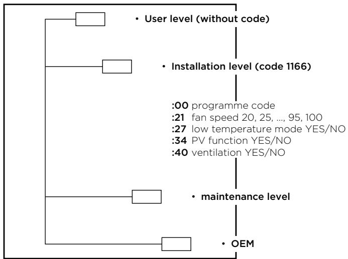
Figure 13: Maintenance levels structure
Maintenance level access
- By pressing field no. 4, you can activate the maintenance mode (Figure 14).
- A display menu with an inscription "code" in the filed CLOCK appears. Enter the maintenance code (fields FN1, FN2, FN3, FN4, FN5 in FN6 for numbers 1, 2, 3, 4, 5, 6).
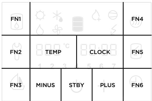
Figure 14: Fields display
- If you do not press any field for 10 s, the programme returns to the start menu.
- If the code is incorrect, the programme returns to previous operation.
- If the code is correct, the first parameter appears on the display. The number on the right is the serial number of the parameter and the field on the left is intended for its value.
- The first parameter :00 is a version of a software code and serves information purposes only.
- By pressing the right number (Field CLOCK in Figure 14) you proceed to the next parameter.
Installation level (code 1166)
After the first code entry for the installation level the programme allows access to the following parameters:
:00programme code
:21 fan speed 20, 25, ..., 95, 100
:27 low temperature mode YES/NO
:34 PV function YES/NO
:40 ventilation YES/NO
Fan speed settings (parameter: 21)
Select the parameter :21 and set the fan speed by pressing (+) or (-) (20% - 100%). See the numerical value settings on the left side in field 5. When the fan speed is set, you can save the changes by waiting a few moments or by pressing no. 4.
Setting low-temperature mode (parameter :27)
Select the parameter :27 and change the temperature by pressing (+) or (-) . The temperatures depend on the model of the heat pump.
The low-temperature mode is possible only if the heat pump model enables this function!***
The settings are shown on the left side (in the field TEMP):
Yes - heat pump, operation mode of the heat pump (higher than -7^ ), the system contains a 4-way valve.
No - heat pump, operation mode of the heat pump (higher than 7^ ), the system contains a 4-way valve.
PV function activation (photovoltaics) (parameter :34)
Yes - activated
No - deactivated
Fan activation (parameter :40)
Yes - activated
No - deactivated
Anti-legionella function
- Works only when the heat pump is switched on. When activated, symbol no. 17 is displayed.
- Automatic activation: every 2 weeks of operation of the heat pump.
- Anti-legionella programme can be activated manually by pressing field no.15.
Ventilation
- Activate ventilation by pressing field no. 2. The function is automatically switched off after 30 minutes.
- By shortly pressing the filed 2 again, the ventilation is deactivated.
- By shutting down the heat pump with the on/off options the ventilation is deactivated.
- In case of power failure while the ventilation is activated, the ventilation will proceed after the reconnection of the power supply for the remaining time but no longer than 30 minutes.
- In the event of any other failure the ventilation is deactivated.
-
Ventilation cannot be activated:
-
in case of any kind of failure
- during antilegionella function operation
- during defrosting.
- Symbol 2 is active and visible.
Backup mode
- Activate backup mode by pressing field no. 2.
- Backup mode uses heaters and is activated when an error occurs on the aggregate.
The water is heated with heaters.
- By pressing field no. 2 backup mode is deactivated.
- Symbol 3 is displayed.
- If the backup mode is activated, please contact the maintenance services.
Operation signalization
Antilegionella programme:
- activated - control field 17 is displayed
- deactivated - control field 17 is not displayed
Electrical heater:
- activated - control field 14 is displayed
- deactivated - control field 14 is not displayed
Heat pump:
- activated - control field 16 is displayed
- deactivated - control field 16 is not displayed
On/off:
- activated - control field 9 and other fields are displayed
- deactivated - control field 9 is displayed
Defrosting:
- activated - control field 19 is displayed
- deactivated - control field 19 is not displayed
Fan on/off:
- activated - control field 20 is displayed
- deactivated - control field 20 is not displayed
Ventilation on/off (by pressing field no. 2):
- activated - control field 2 is displayed
Backup mode on/off (by pressing field no. 2):
- activated - control field 3 is displayed
- deactivated - control field 3 is not displayed
PV (PHOTOVOLTAICS)
- In case of voltage free contact between clamps 1 and 2 PV is activated (Figure 17).
- In case of voltage free contact between clamps 1 and 2 field 1 is displayed.
- The voltage free contact requires 800W of electrical power.
- PV is deactivated in default settings.
- PV is activated in the installation menu with the activation of parameter 34.
- Set PV functions prior to time settings.
- PV mode does not affect the backup mode.
- The antilegionelle cycle is performed regardless the state of the PV mode.
PV operation (activated):
- PV is activated and the operation of the heat pump is allowed. The heat pump heats the water to the maximum temperature (see technical characteristics table). The heater is activated.
- No contact between PV clamps and the heat pump operation is allowed. The heat pump heats the water temperature up to 40^ .
Opening the EPP maintenance cover
Models PAW-DHWM300A/AE
- To remove a small part of the maintenance cover, pull on the bottom side.
- To remove the larger part of the maintenance cover, pull on the bottom side.
Take reverse steps for closing the cover.
Model PAW-DHWM200A
Take step 2 of the PAW-DHWM300 models.
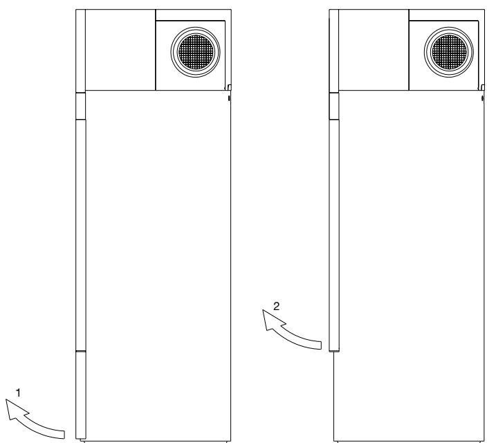
Figure 15: Opening the EPP maintenance cover
PV detection
The connection of the PV module to the heat pump must be performed by a qualified expert. On the back side of the heat pump, under the connection cord, there is a PV connection port. The PV port is shown in figure 16. Use a connection cord (minimum inner cross-section 0,5mm^2 , H05VV-F 2G 0,5 mm² and maximum external cross-section of 10 mm). The removal of the cover is described in the chapter above
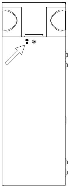
Figure 16: PV connection location
Connect the cord to the clamp, located under the control unit. The connection location is marked with PV. Use ports 1 and 2.
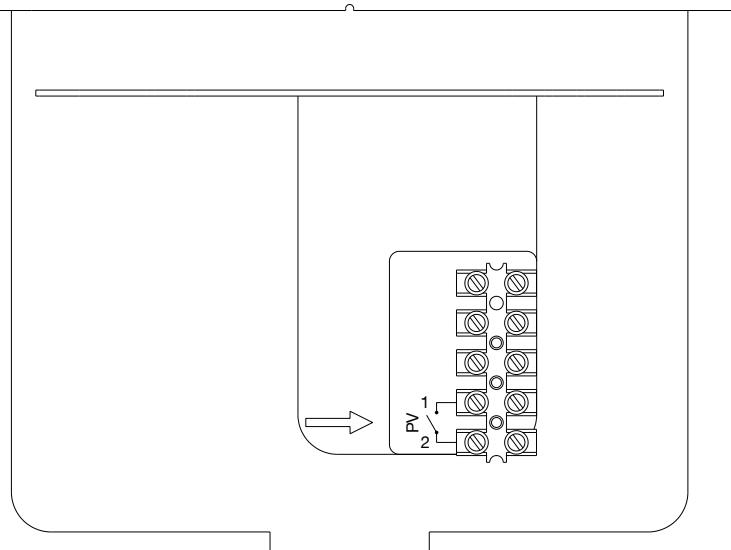
Figure 17: PV connection port
After the connection to the water supply mains and other heating sources the hot water tank with the heat pump is ready for use. If there is any possibility the water in the tank could freeze, you must drain the water from the tank. To do so, open the hot water lever at one of the mixing batteries, connected to the hot water tank. The water is drained via a drain valve on the inlet water pipe.
The exterior of the heat pump should be cleaned with a mild detergent solution. Do not use solvents or abrasive cleaning agents. If the heat pump was exposed to dust, evaporator lamellas might become blocked, which can have a detrimental effect on the functioning of the heat pump.
By providing regular service check-ups, you can ensure flawless operation and long life of the heat pump. The corrosion warranty for the tank only applies if you carry out regular inspections of the protective anode. The period between inspections must not exceed 36 months. The inspection must be performed by an authorised expert. The inspection must be marked on the warranty document of the product. The inspection will check the anti-corrosion protection anode and if necessary clean the limescale, which builds up in the tank depending on the quality, quantity and temperature of water. The maintenance expert will recommend the date for the next inspection.
Despite careful production and control, the heating pump can produce errors that must be solved by an authorised service provider.
Before calling your maintenance provider, check the following:
- Is everything OK with the power supply network?
- Is the air outlet obstructed (evaporator can freeze)?
- Is ambient temperature too low (evaporator can freeze)?
- Can you hear the operation of the compressor and fan?

Do not try to eliminate malfunctions by yourself, call your nearest authorized service provider!
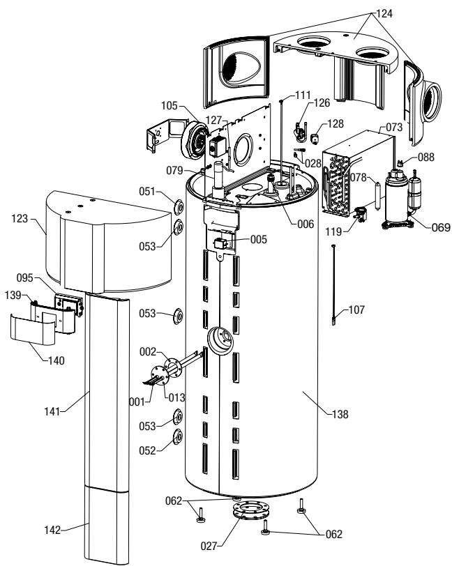
Image 18: Exploded-view drawing
| Position | Ident | Spare part description | Quantity | Validity |
| 1 | 458697 | Heating Element 1000W | 2 | |
| 2 | 496134 | Gasket 100/60X3 | 1 | |
| 5 | 506660 | Thermal Cut-out | 1 | |
| 6 | 543154 | Mg Anode D26 - Chain | 1 | |
| 13 | 524462 | Heater Flange | 1 | |
| 27 | 765011 | Gasket 180/114x3 | 1 | |
| 28 | 321732 | Filling Valve Assy | 2 | |
| 51 | 512464 | Rosette D80/D31X20 RD | 1 | |
| 52 | 512465 | Rosette D80/D31X20 BU | 1 | |
| 53 | 512463 | Rosette D80/D31X20 BK | 1 | PAW-DHWM200A PAW-DHWM300A |
| 53 | 512463 | Rosette D80/D31X20 BK | 3 | PAW-DHWM300AE |
| 62 | 765083 | Adjustable Foot M12x71 | 4 | |
| 69 | 407206 | Compressor | 1 | |
| 69 | 519943 | Compressor | 1 | |
| 88 | 419383 | Thermal Cut-out | 1 | |
| 73 | 496119 | Evaporator | 1 | |
| 73 | 496131 | Evaporator | 1 | |
| 78 | 364934 | Drying Filter 30 g | 1 | |
| 79 | 409396 | Capacitor 15mF | 1 | |
| 95 | 405088 | Electronics | 1 | |
| 105 | 496009 | Centrifugal Fan | 1 | |
| 107 | 506710 | Temperature Sensors | 1 | |
| 111 | 531227 | Sensor Strip 200L | 1 | PAW-DHWM200A |
| 111 | 506529 | Sensor Strip 300L | 1 | PAW-DHWM300A PAW-DHWM300AE |
| 119 | 440608 | Thermal expansion valve TUB-R134 | 1 | |
| 123 | 496006 | Front Protection Cap | 1 | |
| 124 | 496007 | Back Protection Cap | 1 | |
| 126 | 392462 | 4-Way Valve | 1 | |
| 127 | 451725 | Check Valve | 1 | |
| 128 | 443882 | 4-Way Valve Coil | 1 | |
| 138 | 535754 | Casing 200 | 1 | PAW-DHWM200A |
| 138 | 517236 | Casing 300 | 1 | PAW-DHWM300A |
| 138 | 517237 | Casing 300-1 | 1 | PAW-DHWM300AE |
| 139 | 518197 | Electronics Holder | 1 | |
| 140 | 517324 | Screen Foil | 1 | |
| 141 | 523139 | Service Channel Cover 200 | 1 | |
| 142 | 496135 | Service Channel Cover 300 | 1 | PAW-DHWM300A PAW-DHWM300AE |
Despite careful production and control, the heating pump can produce errors that must be solved by an authorised service provider.
Indicator of errors
- In case of an error on the appliance, the beeper starts beeping and field no. 4 starts flashing. When you press field no. 4 the error code is displayed in field no. 12.
| Error | Description of error | Solution |
| E004 | • Freezing. The error appears if the temperature in the heat pump is below 5 °C. | • Call the service. |
| E005 | • Overheating (temperature > 75 °C, electronic regulator failure). | • Unplug the heat pump from the power supply. Call the service. |
| E006 | • Mg anode error. | • Call the service (heat pump functions normally). |
| E007 | • Volume and/or temperature sensors error. | • Call the service. |
| E042 | • Anti-legionella function error. | • Press field no. 4 to restart. |
| E247 | • Defrosting error. | • Automatically turns on heating with the electric heater. When the error is deleted, the aggregate resumes its normal operation. |
| E361 | • External air sensor error. | • Call the service (automatically switches to the electric heater). |
| E363 | • Defrosting sensor error. | • Call the service (automatically switches to the electric heater). |
WE RESERVE THE RIGHT TO ANY MODIFICATIONS NOT AFFECTING THE FUNCTIONALITY OF THE APPLIANCE.
The instructions for use are also available on our website www.aircon.panasonic.eu.