PNK-1 - Alarm system Satel - Free user manual and instructions
Find the device manual for free PNK-1 Satel in PDF.

| Product Type | Alarm system keypad |
| Dimensions (H x W x D) | 120 x 80 x 25 mm |
| Weight | 150 g |
| Power Supply | 12 V DC |
| Current Consumption | 50 mA (standby), 100 mA (active) |
| Operating Temperature | -10°C to 55°C |
| Keypad Type | Membrane keypad with backlight |
| Number of Keys | 12 (0-9, *, #) |
| Indicators | LED for status (armed/disarmed/trouble) |
| Main Functions | Arm/disarm, panic alarm, programming, zone bypass |
| Installation | Wall mount with screws (included) |
| Compatibility | Satel alarm control panels |
| Wiring | 4-wire connection (power, data, tamper) |
| Maintenance | Clean with a soft dry cloth; avoid liquids |
| Safety | Low battery indication; tamper detection |
| Spare Parts | Not available separately; contact supplier |
| Repairability | No user-serviceable parts; professional repair |
| Certifications | CE, EN 50131 |
| Package Contents | Keypad, screws, user manual |
Frequently Asked Questions - PNK-1 Satel
User questions about PNK-1 Satel
0 question about this device. Answer the ones you know or ask your own.
Ask a new question about this device
Download the instructions for your Alarm system in PDF format for free! Find your manual PNK-1 - Satel and take your electronic device back in hand. On this page are published all the documents necessary for the use of your device. PNK-1 by Satel.
USER MANUAL PNK-1 Satel
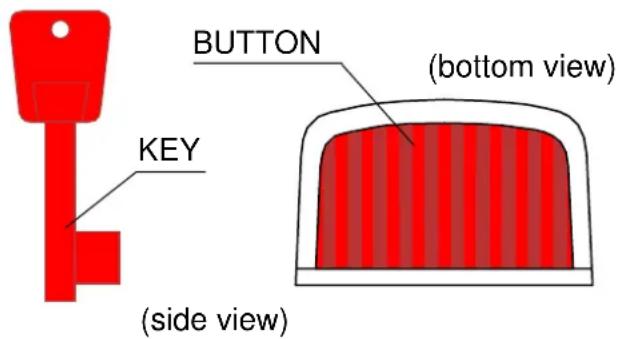
The panic button is a device designed to instantly trigger the alarm and/or initiate the procedure of reporting an emergency situation in protected facility to the MONITORING STATION. It can be used in banks, wholesale depots, stores, and other facilities exposed to a direct assault and robbery.
It can interface with any alarm control panel which supports the NC type detectors. Installed inside the button is a reed relay, the contacts of which open on pressing the button.
The button return spring can be easily removed, thus enabling the, so-called, mechanical memory of use. With the spring removed, the button – after being pushed in – will remain
natural_image
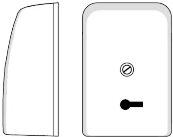
Two simple electrical switch components: a closed panel and a rectangular door with a circular button and key (no text or symbols)Fig. 1. View of the panic button and key
inside the casing until it is released with the key. Where a few buttons are connected to one zone of the alarm control panel, this function makes it possible to identify the button which triggered the alarm.
INSTALLATION AND CONNECTION
Prior to installation, break off the cable inlet in the base or cover of the button. The button should be mounted by means of two screws on an even surface, usually in a concealed place, e.g. under the top of writing desk. It can be installed either horizontally, or vertically.
If several buttons are connected to one panic zone of the alarm system, they should be connected in series.
The ends of reed relay should be connected with the cables by means of field terminals. Three field terminals make it possible to connect the EOL resistor inside the housing, without the use of a soldering iron. To make the installation easier, you can take out the movable button from the base after slightly deflecting the catches.
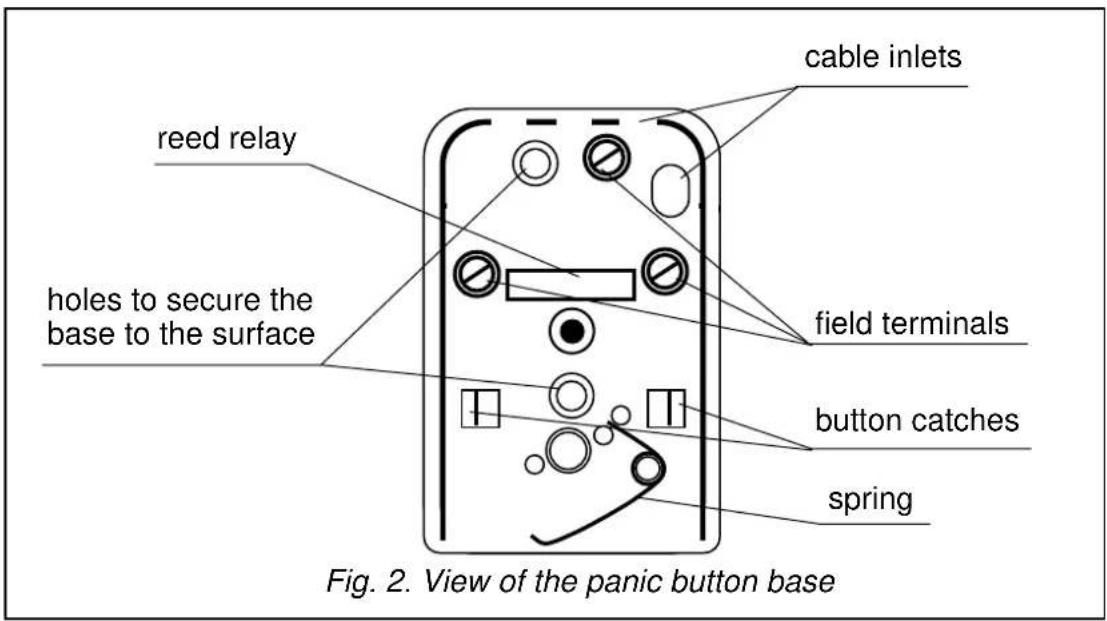
CAUTION! Be particularly careful during installation so as not to damage the glass enclosure of reed relay or the magnet situated on the button.
SPECIFICATIONS
Maximum switchable voltage, reed relay 160V
Maximum switchable current 250mA
Maximum continuous current (not switchable) 1.5A
Maximum switchable power....5VA
Transient resistance 130mΩ
Contact material ...... Ru (Rutenum)
Dimensions....40x60x25mm
Weight 27g
The latest EC declarations of conformity and certificates are available for downloading on the website www.satel.pl

SATEL sp. z o.o.
ul. Schuberta 79
80-172 Gdańsk
POLAND
tel. + 48 58 320 94 00
info@satel.pl
www.satel.pl