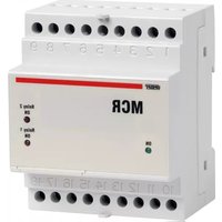
MCR230 - Electrical relay Vemer - Free user manual and instructions
Find the device manual for free MCR230 Vemer in PDF.


| Product Type | Programmable Thermostat / Temperature Controller |
| Brand | Vemer |
| Model | MCR230 |
| Dimensions (HxWxD) | Approx. 100 x 80 x 30 mm |
| Weight | Approx. 150 g |
| Power Supply | 230 V AC, 50/60 Hz |
| Display Type | LCD with backlight |
| Temperature Range | 5°C to 35°C |
| Programming Modes | Daily and weekly programmable schedules |
| Main Functions | Room temperature control, frost protection, manual override, holiday mode |
| Control Output | SPST relay, max 16 A resistive |
| Sensor Type | Internal NTC thermistor |
| Accuracy | ±0.5°C |
| Protection Class | IP20 (indoor use only) |
| Operating Temperature | 0°C to 50°C |
| Storage Temperature | -10°C to 60°C |
| Wiring | 3-wire (L, N, load) or 2-wire for valves |
| Mounting | Wall-mounted (flush or surface box) |
| Maintenance | Clean with dry soft cloth; avoid liquids |
| Safety | Double insulation, automatic safety shut-off at high temperature |
| Spare Parts & Repairability | Contact Vemer customer service for replacement parts; device is not user-serviceable |
| Certifications | CE marked, RoHS compliant |
Frequently Asked Questions - MCR230 Vemer
User questions about MCR230 Vemer
0 question about this device. Answer the ones you know or ask your own.
Ask a new question about this device
Download the instructions for your Electrical relay in PDF format for free! Find your manual MCR230 - Vemer and take your electronic device back in hand. On this page are published all the documents necessary for the use of your device. MCR230 by Vemer.
USER MANUAL MCR230 Vemer
Read all the instructions carefully
■ The motor control relay MCR is an electronic command device in a standardised 4-module DIN container, to control the motor alternation.
SAFETY WARNINGS
During the installation and operation of the instrument, proceed in accordance with the instructions below:
1) The instrument should be installed by a competent operator following the installation diagrams carefully
2) The instrument should be installed in a panel from which no access can be gained to the terminals after installation
3) Do not power or connect the instrument if any part of it is damaged
4) The electrical system of the building in which the instrument is to be installed should have a switch and a protective device against over-currents
5) The instrument is designed for installations with over-voltage category III and pollution level 2, in accordance with the EN 61010-1 standard.
Code Model Description
| VP813000 | MCR048 | Motor alternation relay 24/48 V |
| VP812200 | MCR230 | Motor alternation relay 115/230 V |
| VP811400 | MCR400 | Motor alternation relay 400 V |
TECHNICAL SPECIFICATIONS
• Power supply: 24/48/115/230/400 V\~ (-15% ÷ +10%), 50/60 Hz
• Absorption: 3,5 VA (2,5 W)
• Terminal: 6 mm ^2 block
- Relay 1 output: - relay with exchange contact 8A / 250V - maximum switchable power 2000 VA cos =1
- Relay 2 output: - relay with exchange contact 8A / 250V - maximum switchable power 2000 VA cos =1
- Signalling: – Green LED: power on
– Red LED: relay 1 intervention
– Red LED: relay 2 intervention
• Operating temperature: -5^ ÷ +50^
• Storage temperature: -10^ ÷ +70^
• Humidity: 20%÷90%, non-condensing
- Insulation: power supply and load circuits, galvanically insulated at reinforced insulation level in accordance with the EN 61010-1 standard
- Container: 4-module DIN, colour RAL-7035 grey
- Casing material: self-extinguishing in class V0, in accordance with the UL-94 standard
• Degree of protection: IP20/IP51 when correctly installed in an electrical panel
USE
- This device is designed to give the balanced wear and tear of pumps, compressors, generators, etc., when two units, one in operation and one back-up, are installed.
- The operating principle is based on the alternation of the motor start-up commands each time the input contact piloted by an outside automatic device (such as a pressure switch) is closed.
- As well as this type of alternation, this type of relay can also be used for the alternate/simultaneous command of two motors, and for the cascade command of two motors.
OPERATING
■ ALTERNATING COMMAND OF TWO MOTORS
- In this case, only the mainP1/G1 contact is used, piloted by an outside automatic device (such as a pressure switch/float).
- Each intervention of the P1/G1 contact causes the alternating start-up of one of the two motors, exchanging the operating function (see the “Operating Diagram 1”).
■ ALTERNATING/SIMULTANEOUS COMMAND OF TWO MOTORS
- In this case the main P1/G1 contact and the secondary P2/G2 contacts are used, piloted by two outside automatic devices (such as two pressure switches) adjusted to two different intervention thresholds.
- Each intervention of the P1/G1 contact causes the alternating tart-up of one of the two motors, exchanging the operating function.
- The intervention of the P2/G2 contact causes the start-up of the second motor, thus setting up the emergency help function (when, for example, a single pump is unable to satisfy the pumping requirements.
See the "Operating Diagram 2" - When the power supply line is inserted when both the P1/G1 and P2/G2 contacts are closed, the start-up of the second motor is delayed by 2 seconds, thus halving the thrust current and the consequent oscillation of the coil supply voltage.
- The secondary P2/G2 contact also guarantees the emergency help function in the event of failure of the main P1/G1 contact.
- This therefore makes it possible to start-up one of the motors instantaneously, and the back-up motor after a delay of 2 seconds.
■ CASCADE COMMAND
- When 2 or more relays are used, the cascade operation of 3 or more motors is possible, with the exchange of the operating and emergency help functions of the various motors as required..
REFERENCE STANDARDS
Conformity to the EU directives:
2006/95/EC (Low Voltage)
89/336/EEC modified by 92/31/EEC and 93/68/EEC (EMC)
is declared with reference to the following harmonised standards:
Safety: EN 61010-1
Electromagnetic compatibility: EN 61000-6-2, EN 61000-6-4
Brand : Vemer
Model : MCR230
Category : Electrical relay