UH8055S - Radio UNIDEN - Free user manual and instructions
Find the device manual for free UH8055S UNIDEN in PDF.

| Product Type | UHF CB Two-Way Radio |
| Brand | Uniden |
| Model | UH8055S |
| Dimensions (Approx.) | 140 x 56 x 38 mm (5.5 x 2.2 x 1.5 in) |
| Weight (with battery) | 160 g (0.35 lbs) |
| Power Output | 5 W (max) |
| Power Supply | Rechargeable Li-Ion battery pack (7.4V, 1200 mAh) |
| Frequency Range | 476.425 – 477.9875 MHz (UHF CB Band) |
| Channels | 40 (including frequency and channel pairs) |
| Key Functions | Scan, dual watch, monitor, CTCSS/DCS, roger beep, key lock, backlit display |
| Weather Alerts | Yes (NOAA weather channels and alert) |
| Range (Typical) | Up to 5 km (open area), depends on terrain |
| Microphone | Built-in electret condenser |
| Speaker | Built-in 36 mm dynamic speaker |
| Display | LCD with channel number, battery status, signal strength |
| Operating Temperature | -20°C to +60°C (-4°F to 140°F) |
| Battery Life | Approx. 12 hours (5-5-90 duty cycle) |
| Charging | Desktop charger with AC adapter (included) |
| Care and Cleaning | Wipe with a soft, dry cloth. Do not use harsh chemicals. |
| Safety | Use only approved battery/charger; avoid exposure to rain; comply with RF exposure guidelines. |
| Spare Parts & Repairability | Contact authorized Uniden service center for repairs; battery and antenna are user-replaceable. |
Frequently Asked Questions - UH8055S UNIDEN
User questions about UH8055S UNIDEN
0 question about this device. Answer the ones you know or ask your own.
Ask a new question about this device
Download the instructions for your Radio in PDF format for free! Find your manual UH8055S - UNIDEN and take your electronic device back in hand. On this page are published all the documents necessary for the use of your device. UH8055S by UNIDEN.
USER MANUAL UH8055S UNIDEN
For more exciting new products please visit our website:
Australia: www.uniden.com.au
OWNER'S MANUAL
Introduction 4
Controls & Connectors 5
Indicators 8
Included with your UH8055S 9
Optional Accessories 10
DIN Installation 11
Connecting the Microphone 13
Mounting the MIC Hanger 14
Operation 16
Turning on the Power 16
Setting the Volume 16
Setting the Manual Squelch 17
Setting the Auto Squelch 17
Selecting a Channel 19
Channel Banks - Using the POLICE button 19
Programming the Instant Priority Channel 20
Recalling the Instant Channel 20
Transmitting 20
CTCSS (Continuous Tone Coded Squelch System) 21
DCS (Digital Coded Squelch) 21
Call Tone Function (Wake Up Tones) 22
DUAL Watch 22
Using Repeater Channels 23
Operating the UHF CB Radio in Duplex Mode 24
Scanning 24
Add/Remove Channels from SCAN Memory 25
Master Scan Mode 25
Open Scan (OS) Mode 27
Group Scan (GS) Mode 28
Priority Watch 29
Selecting the Call Tone (Wake Up Tone) 29
Busy Channel Lockout 30
Roger Beep 30
Key Beep On/Off 31
Alpha Tag 31
Volume Sync 3
Backlight Colour 33
Backlight Level 33
LCD Contrast 33
Operation - Special Features 34
100 User Programmable RX Channels 34
Manually Programme a RX Channel 34
Store a Police/Fire frequency to a RX Channel 35
Store a frequency found using CLOSE CALL to a RX Channel 35
Instant Replay 36
Turning Instant Replay On/Off 36
Close Call RF Capture 37
Using Close Call 38
Selective Calling 39
Programming the Selcall ID for your UH8055S 40
Storing Selcall IDs of other users to the ID Memory 40
Tone Calling (Making a Selcall Call) 41
Receiver Quiet (TSQ) Mode 41
To Activate/Deavtivate Tone Squelch (TSQ) on a Channel 42
Receiving a Selcall 42
Scanning Tone Squilched Channels 43
Group Calling 44
Selcall ID Format 44
Selcall Settings 45
Tone Period 45
Lead-in Delay 45
Lead-in Delay Programming 46
Lead-in Tone 46
Alarm mode 47
Call Alarm Continue Mode 47
Group Call Mode 47
SELCALL Tone Frequency List 48
CTCSS Codes Table 48
DCS Codes Table 49
UHF CB Channel Guidelines 50
UHF CB Channels & Frequencies 51
Warranty 53
The Uniden UH8055S is designed to provide you with years of trouble free service. Its rugged components and materials are capable of withstanding harsh environments. Please read this Operating Manual carefully to ensure you gain the optimum performance of the unit.

NOTE
The citizen band radio service is licenced in Australia by ACMA Radio-communications (Citizen Band Radio Stations) Class Licence and in New Zealand by MBIE General User Licence for Citizen Band Radio and operation is subject to conditions contained in those licenses.
Features
• UHF-CB Narrow Band (NB) Transceiver Radio ^1
- 80 Channel
• 5W Transmission Power
• Built-in AVS Circuitry
- Duplex Capability
• Built-in Selective Calling (SELCALL) Feature with Alpha Tag
• Roger Beep Function On/Off
• 10 Different Call Tones
Special Features
• 100 Extra User Programmable Receive Only Channels with Apha Tag ^2
• Pre-Programmed Police, Fire & Ambulance Frequencies ^2
- Instant Replay of Recent Received Signals
- Close Call ^M RF Capture Feature ^2
Control Features
- Optional Remote LCD Speaker Microphone (Remote SPK/MIC) with Extension Cable
• LCD Display with 7 Backlight Colours
• LCD Brightness & Contrast control - Mobile DIN Size with DIN Sleeve and Removable Bracket
• +12V to +24V DC Power Input
• Under and over voltage alert function
• Signal Strength/ Power Meter
• Volume Control
• External Speaker Jack
• Power On/Off Push Switch
• Front and Rear MIC Jacks for increased mounting options
- Variable Squelch Level adjust or Auto Squelch with optional Remote SPK/MIC
Channel Features
- Channel Select
- Instant Channel Programming
• One touch Instant Channel recalling
• Dual Watch with Instant Channel
• Group Scan and Priority Channel Watch - Open Scan
- MASTER Scan
- Scan Channel Memory On/Off separately with Open Scan, Group Scan
- Busy Channel Lock-out Function
• 38 Built-in CTCSS (Continuous Tone Coded Squelch System) codes
• 104 additional DCS (Digital Coded Squelch) codes that are user selectable
^1 Refer to p.51 - p.52 for channel information
2 Available frequencies & channels are within 400-520MHz Band only in 12.5kHz steps. Police, Fire & Ambulance reception is unencrypted analogue.
^3 AVS - Automatic Volume Stabilizer detects and manages incoming audio to comparable levels.
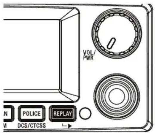
UH8055S Base Front View
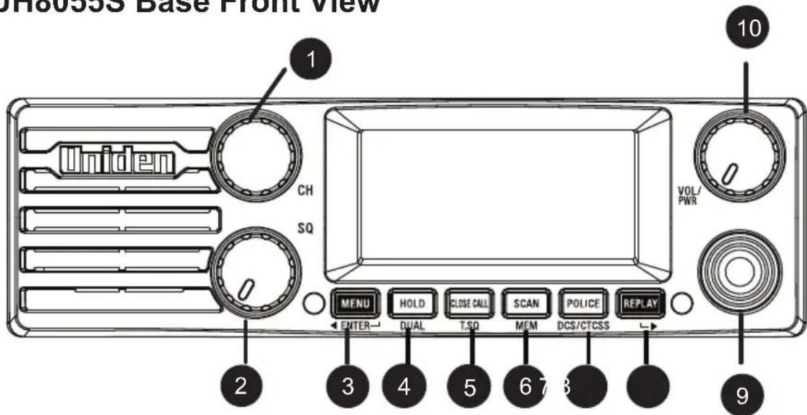
Controls and Connectors
1 Rotary CHANNEL Selector
2 SQ - Rotary Squelch control
3 MENU/ENTER - Menu and Select button
- Move Selection Left
4 HOLD/DUAL- Hold and Dual watch button
5 CLOSE CALL/T.SQ - Close Call and Tone Squelch Channel
6SCAN/MEM-ScanandMemorybutton
7 POLICE/DCS/CTCSS - Police/CB/Fire Button. DCS and CTCSS Tone button
8 REPLAY - Replay Function button
- Move selection right
9 MIC - Front Microphone Jack
10 VOL/PWR - Rotary Volume Control
Power On/Off Push control
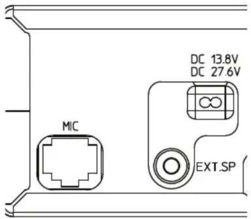
UH8055S Base Rear View
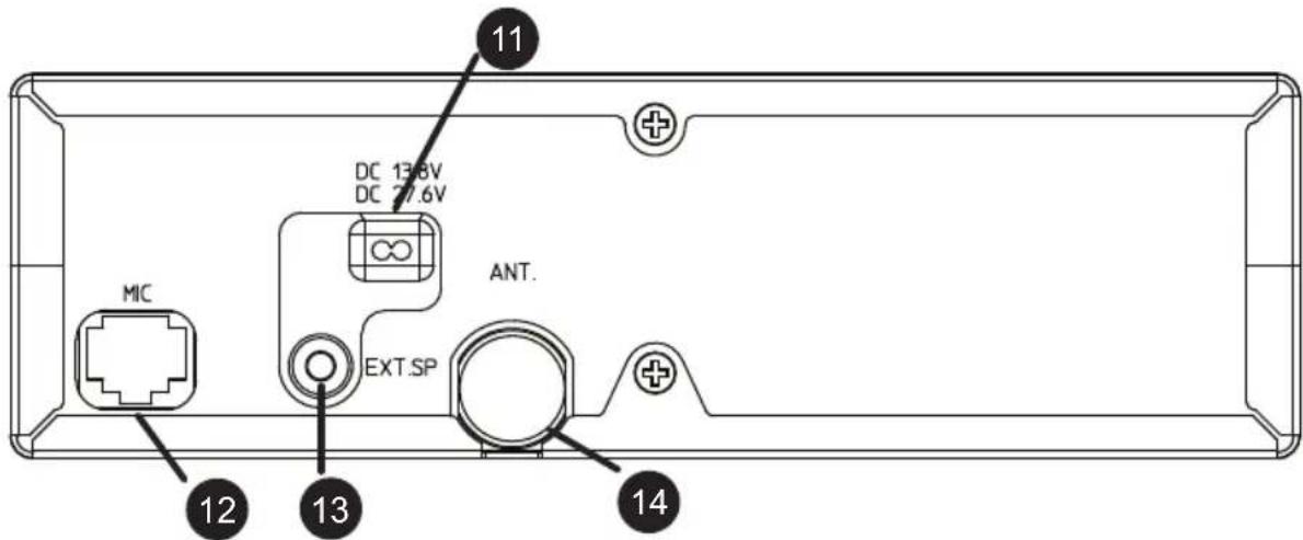
Connectors
11 Power Input Connection
12 Rear MIC Jack
13 External Speaker Jack
14 UHF Antenna Connection
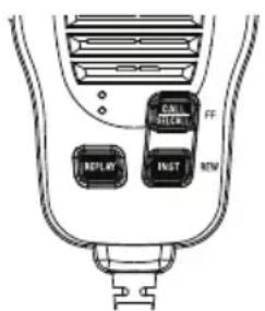
Heavy Duty Speaker Mic
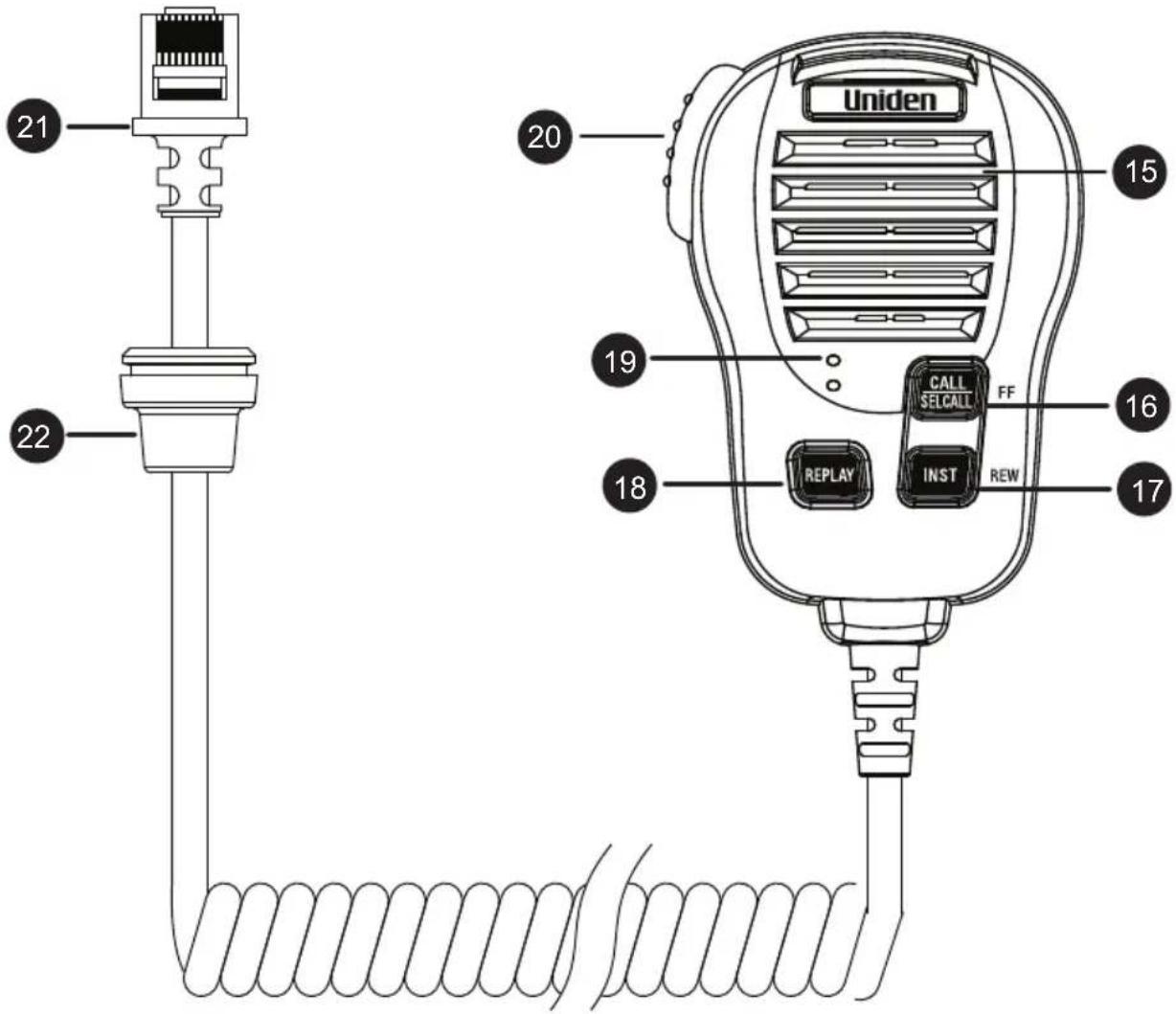
Controls and Connectors
15 SPEAKER
16 CALL/SELCALL/FF-
Call Tone Button
Selective Calling Button
Select FF while replaying
17 INST/REW - Instant Channel Button/Select REW while replaying
18 REPLAY - Replay Function Button
19 MICROPHONE
20 PTT - Push To Talk Button
21 RJ45 type plug
22 Front MIC Jack Cover
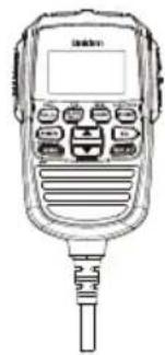
Remote LCD Speaker MIC (Optional)
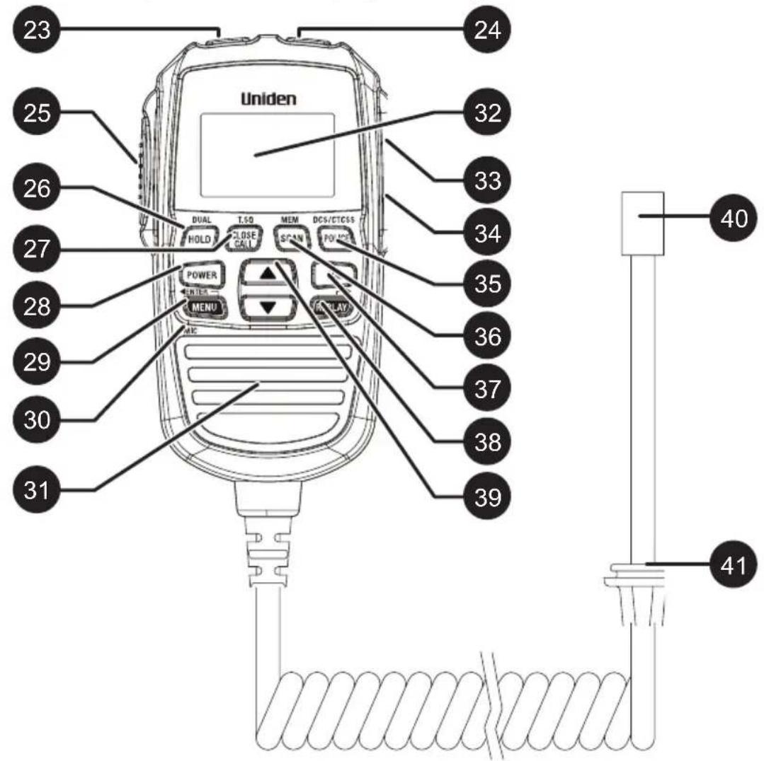
Controls and Connectors
23 CALL/SELCALL -
Call Tone Button
Selective Calling Button
24 INST - Instant Channel Button
25 PTT - Push To Talk button
26 HOLD/DUAL - Hold and Dual Watch Button
27 CLOSE CALL/T.SQ -
Close Call and
Tone Squelch Button
28 POWER - Power Button
29 MENU/ENTER - Menu and
Select Button
- Move Selection Left
30 MICROPHONE
31 SPEAKER
32 Liquid Crystal Display (LCD)
33 VOL △ - Volume Up Button
34 VOL ▼Volume Down Button
35 POLICE - Police/CB/Fire Button
/DCS/CTCSS - DCS & CTCSS Button
36 SCAN/MEM - Scan and Memory Button
37 SQL - Squelch Button
38 REPLAY - Replay Button
- Move selection right
39 ▲ / -Select Up and Down
Buttons
40 RJ45 type plug
41 Front MIC Jack Cover
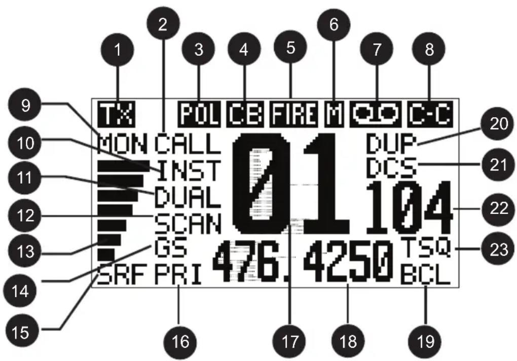
1 TX/BUSY - Transmit/Busy
2 CALL/CAL - Call Tone Transmit/ Selcall Transmit
3 POL - Police Bank
4 CB - UHF CB + Extra RX
Channel Bank
5 FIRE - Fire (+ Ambulance) Bank
6 M - Channel in Memory
7 00 - Replay Function is enabled
8 C-C - Close Call mode
9 MON/SQT - Flashing: Monitor/Tight Squelch
10 INST - Instant Channel
11 DUAL/HOLD - Dual Watch/Hold
12 SCAN - Scan mode
13 Signal Power Level
14 GS - Group/MASTER Scan
15 S/RF- Receive Signal or Transmit
16 PRI - Priority Channel Watch
17 UHF-CB Channel
18 Channel Frequency/Alpha Tag display
19 BCL - Busy Channel Lockout
20 DUP/LIST - Duplex Channel/ Close Call lockout list
21 DCS/CTCSS - DCS/CTCSS selected
22 DCS/CTCSS Code Number/Extra RX Channel Indicator
23 TSQ - Tone Squelch enabled
Included with your UH8055S Transceiver
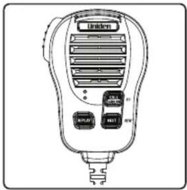
Heavy Duty Sp Mic (MK870)
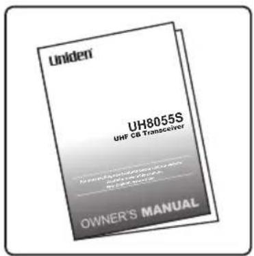
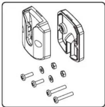
Owner's Manual Microphone Hanger with screws, washers
natural_image
Technical illustration of mechanical components including a housing and bolt assembly (no text or symbols)screws, washers
natural_image
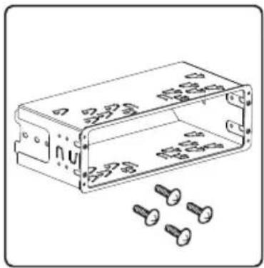
Technical line drawing of a rectangular electronic enclosure with multiple screws and mounting holes (no text or symbols)Din Mount Sleeve, Removable Bracket & Screws
natural_image
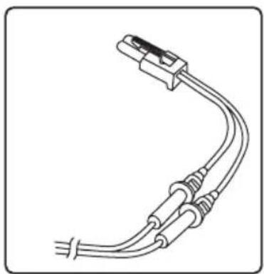
Line drawing of a U-shaped electrical plug with three leads and terminal connectors (no text or symbols)DC Power Cord with fuse
natural_image
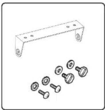
Technical line drawing of a metal bracket with multiple bolt holes and separate view of mechanical components (no text or symbols)Mounting Bracket Mounting Screws Washer Starts and Screws
natural_image
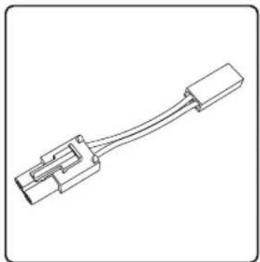
Line drawing of a mechanical connector or connector with a straight cable (no text or symbols)Adaptor Cable
natural_image
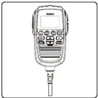
Line drawing of a handheld electronic device with control panel and connector (no text or symbols)Remote LCD Speaker Microphone (RM880)
natural_image
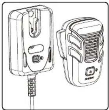
Line drawing of two electronic devices with connectors and a spring-like base (no text or symbols)DECT Wireless Speaker Microphone (MK800W)
natural_image
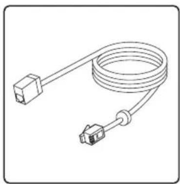
Line drawing of a coiled cable with two connectors (no text or symbols)Extension Cable (EC 770)
UHF Antenna - AT-870 External Speaker (MS100)
Mounting Using the DIN Bracket
If you are unsure about how to install your UH8055S in your vehicle using the DIN bracket, consult your automobile manufacturer, dealer, or a qualified installer. The DIN bracket is made up of a sleeve and a frame.
Before installing, confirm that your UH8055S fits in the desired mounting area and you have all the necessary materials to complete the task.
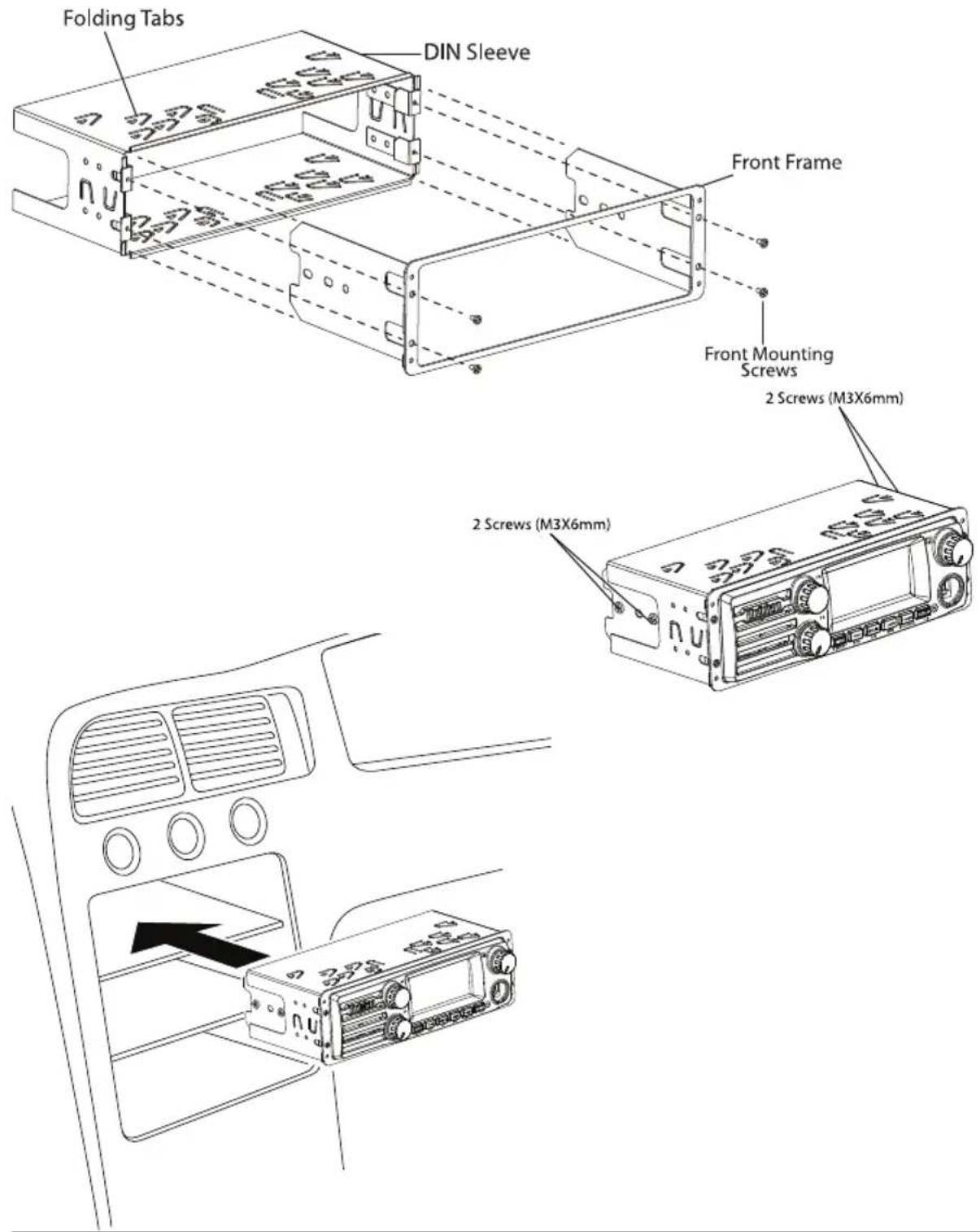
Installing the DIN Bracket
- Remove the 4 front mounting screws to separate the front frame from the DIN sleeve.
- Install the DIN sleeve into the DIN slot of your dashboard and secure it by bending the top and bottom folding tabs.
- Slide UH8055S into the front frame. Ensure the threaded holes on UH8055S line up with holes on the front frame.
- Secure UH8055S onto the front frame using 4 pieces of 6mm screws.
- Attach the DC power leads to UH8055S and your vehicle. RED goes to a positive (+) connection on your fuse block while BLACK connects to the vehicle chassis ground (-).
- Attach the antenna cable, rear MIC and rear speaker to the back of UH8055S if using.
- Make sure all the connections are routed away from any potentially pinching or slicing sheet metal.
- Slide the front frame (with UH8055S attached and all cable connections done) back into the DIN sleeve and secure it using 4 front mounting screws.

If you plan to use the Rear MIC Jack or connect an external speaker at a later time, expect to remove the unit for ease of making those connections.
Connecting the Microphone
Front MIC Jack
Push the MIC plug at the end of the microphone into the MIC jack until the connection locks into place. Gently tug the MIC cord to test that the connection is locked. Use the Front MIC Jack cover which is threaded onto the MIC cord to seal the MIC jack entry from dust.
Disconnecting the MIC from the Front MIC Jack
Pull away the threaded rubber collar and move it down along the cord. Using the flat blade of a screwdriver or similar object carefully press the lock tab at the bottom of the MIC plug and push it upwards. At the same time tug on the MIC cord to draw back the MIC plug.
Rear MIC Jack
Use the Rear MIC Jack if the main base is mounted where a front MIC connection is intrusive or if you wish to use the Remote LCD Speaker MIC with an optional extension cable.
Peel the dust cover from the rear MIC jack. Push the MIC plug at the end of the microphone into the MIC jack until the connection locks into place. An optional 2m extension cable kit is available to enable mounting the main base in a hidden location.

The unit will not function if connected to two Remote LCD Microphones (optional RM880) at the same time.
The Microphone Hanger comes in two parts. How and where you mount the MIC hanger will determine which parts to use.
Conventional Mounting with Screws
Use the front part of the MIC Hanger only.
Locate a suitable mounting position and mark and drill two 3mm holes.
Fix the MIC Hanger into place with screws.
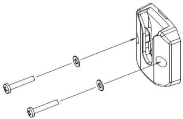
natural_image
Technical line drawing of a mechanical component with multiple cylindrical parts and a housing (no text or symbols)Conventional Mounting with Double Sided Tape (not supplied)
High quality Double-Sided tape can be found at good retail stores.
Secure the front and back pieces of the MIC Hanger using the supplied binding screws.
Locate a suitable mounting position.
Apply high quality Double-Sided tape onto the flat area of the MIC Hanger back piece and then press firmly to the mounting position.
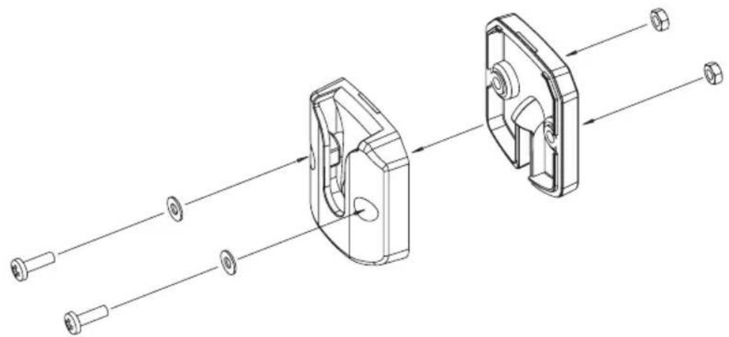
natural_image
Technical line drawing of a mechanical assembly with two views of a housing (no text or symbols)MIC Hanger mounted over MIC Cable

NOTE
The curly cord of the Remote LCD Speaker MIC can extend up to 2m. For practical installation of the MIC Hanger mounted over MIC Cable use this method with the Extension Cable.
Microphone
natural_image
Line drawing of a handheld walkie-talkie device with control panel and antenna (no text or symbols)[Non-Text]
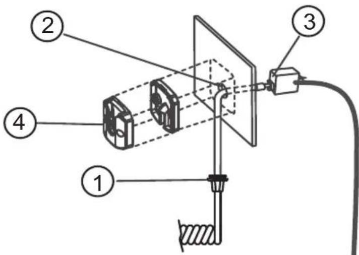
Extension Cable
The plug of the extension cable connects to the Radio. The socket end of the extension cable connects with the microphone plug.
- The rubber collar (dust cover) on the microphone cable is not required and can be cut away or pushed out of the way along the cable.
- Drill a 13mm hole at the MIC hanger location.
- Thread the microphone plug through the hole and connect with the extension cable.
- Mount the MIC Hanger over the hole and cable.
- At the Radio: Connect the extension cable plug to the MIC Jack. Fit the rubber bushing over the MIC jack.
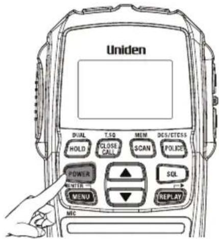
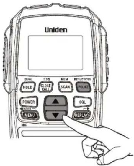
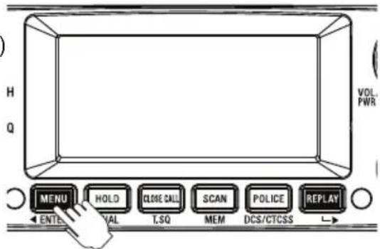
Turning on the Power
Press and hold VOL/PWR control at the base or the [POWER] button on the optional Remote SPK/MIC.
![Press and hold VOLT/WR control at the base or the [POWER] button on the optional Remote SPK/MIC.](/content/2026/05/1056115/images/1e3ce342dd984c1c1c451964a16fddfa4e839d1bcefcac01962093fa3a536f0e.jpg)
Low-Voltage/High-Voltage Alert
The UH8055S can operate on 12VDC (13.8V) or 24VDC (27.6V) power supply, with the range between 10.2VDC to 28.8VDC.

If the power supply voltage exceeds 28.8VDC, an alert tone sounds and HI DC flashes for 5 seconds. The power source must not exceed 32VDC otherwise permanent damage may occur to your radio, which may not be covered by the manufacturer's warranty.
If the input voltage falls below 10.2VDC, LO DC flashes for 5 seconds. The power turns off automatically if voltage falls below 9.0VDC.
Switch your UH8055S OFF and disconnect it from the power source, before locating the cause of the power supply problem.
Setting the Volume
Turn the volume control at the base or press the volume ▲ on the side of the optional Remote SPK/MIC to adjust the volume. The base volume is composed of 42 steps and the optional Remote SPK/MIC is 7 steps.
See Volume Sync on page 32 to synchronize the volume control when the optional Remote SPK/MIC is connected.
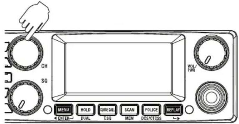
Setting the Manual Squelch
Turn the outer ring of the SQ control at the base to adjust the Squelch.

You must select a channel which is not in use before setting the SQUELCH control. (see p.19 for "Selecting a Channel").
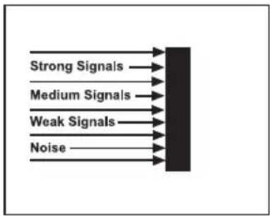
flowchart
graph LR
    A["Strong Signals"] --> C["Processing Block"]
    B["Medium Signals"] --> C
    D["Weak Signals"] --> C
    E["Noise"] --> C
Think of the squelch control as a gate. If you turn Squelch fully clockwise it raises the 'Squelch gate' so high that no signals get through.
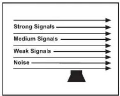
If you turn Squelch fully counter clockwise it lowers the 'Squelch gate' so low that noise gets through.
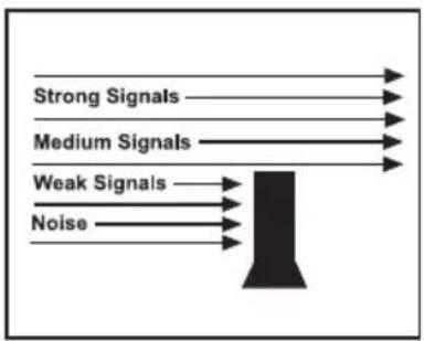
To set the 'Squelch Gate' to the desired level, turn the squelch knob counterclockwise until you hear noise. Then carefully turn the Squelch knob clockwise until the noise fades. Now only strong signals get through.
Setting the Auto Squelch Level
The Auto Squelch feature is available only when the optional Remote SPK/MIC is connected. It has an Off setting and 5 preset squelch levels:
SQL-4 - minimum sensitivity (max/tight squelch)
SQL-3 - medium sensitivity
SQL-2 - moderate sensitivity
SQL-1 - max sensitivity (min squelch)
SQL-0 - Squelch open (monitor)
SQL-OFF
(SQ Volume on the BASE can be activated)
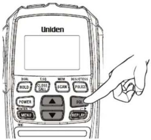
- Press [SQL]. The squelch setting flashes.
- Press ▲ / ▼ on the optional Remote SPK/MIC to change the setting.

- If SQL-0 (squelch open) is selected then MON (monitor) icon flashes.
- If SQL-4 (tight squelch) is selected then SQT icon flashes.
-
Selecting tight squelch mode may prevent the reception of weak signals.
• High noise areas may still break the squelch. -
Press [SQL] to store the setting.
Selecting a Channel
Turn the Rotary Channel Selector at the base or press ▲ / ▼ on the optional Remote SPK/MIC to select the desired channel.
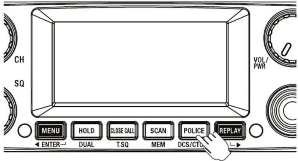
Channel Banks - Using the POLICE Button
The UH8055S has three banks (groups) of channels to select from; CB UHF CB + User programmable RX channels ^1
POL Pre-programmed Police frequencies ^2
FIRE Pre-programmed Fire & Ambulance frequencies ^2
When the CB icon is showing the 80 UHF-CB and any user programmed RX channels will be available for selection or scanning. The 80 UHF-CB channels are numbered 01-80. The user programmable RX channels are numbered 81-180 and only show, in the DCS/CTCSS code area, when programmed.
When the POL icon is showing then pre-programmed police frequencies will be available. When the FIRE icon is showing then pre-programmed fire & ambulance frequencies will be available. The police, fire & ambulance frequencies do not have channel numbers, instead PO appears in the channel display for a police frequency and FI appears for a fire or ambulance frequency.
- Press [POLICE] to select the desired channel bank(s) combination.
The channel banks can be selected as follows;
| ---- | CB | ---- |
| POL | ---- | ---- |
| ---- | ---- | FIRE |
| POL | ---- | FIRE |
| POL | CB | ---- |
| ---- | CB | FIRE |
| POL | CB | FIRE |

^1 Available frequencies & channels are within 400-520MHz Band only in 12.5kHz steps.
^2 Police, Fire & Ambulance reception is unencrypted analogue.
For your reference a list of the available channels, corresponding frequencies and guidelines for their use is printed on p.51 - p.52. For Australia, Channels 05 and 35 are reserved for Emergency Calls.
Programming the Instant Priority Channel
Turn the Rotary Channel Selector at the base to select the Priority Channel you prefer.
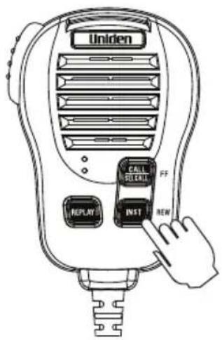
Press and hold [INST] for 2 seconds to store the new setting. INST icon appears to designate the Instant channel.
Recalling the Instant Channel
Momentarily press [INST] to return to the Instant Channel. Press [INST] again to return to the previous channel.
Transmitting
The UH8055S transmits only on UHF-CB Channels.

For your reference a list of the available channels, corresponding frequencies and guidelines for their use and selection is printed on p.51 - p.52. For Australia, Channels 05 and 35 are reserved for Emergency Calls.
Select the desired channel. Press [PTT] on the side of the Heavy Duty Sp MIC and speak normally into the microphone. Hold it approx. 7cm from your mouth. Release [PTT] to end the transmission and listen for a reply.
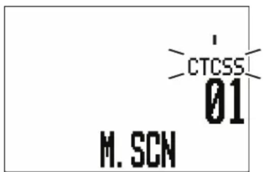
CTCSS (Continuous Tone Coded Squelch System)
Use the CTCSS or DCS privacy codes to talk to UHF-CB users, who are using the same code, without hearing other users on the same channel.
When a CTCSS or DCS tone is set for a UHF-CB channel, the CTCSS or DCS tone is displayed in the DCS/CTCSS code area. For channels with the setting of CTCSS OFF, there will be no display in the DCS/CTCSS code area.

CTCSS and DCS is not available on CH 05 and CH 35. For your reference a list of the available channels, corresponding frequencies and guidelines for their use and selection is printed on p.51 - p.52. For Australia, Channels 05 and 35 are reserved for Emergency Calls.
Rotate the Channel knob on the base to select the desired channel to use CTCSS.
Press and hold [DCS/CTCSS] on the base.
CTCSS icon flashes.
Turn the Rotary Channel Selector at the base or press ▲ / ▼ on the optional Remote SPK/MIC to select DCS/CTCSS code.
Press [DCS/CTCSS] once to store the new setting.
To turn off CTCSS (or DCS) select the oFF code during setting.
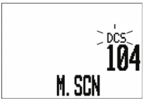
DCS (Digital Coded Squelch)
DCS is a digital extension of CTCSS. It provides 104 extra, digitally coded, squelch codes that follow after the 38 CTCSS codes. CTCSS 1-38, followed by DCS 1-104.
Call Tone Function (Wake Up Tones)
Press the microphone [CALL/SELCALL] Button. A three second wake up ringing tone will be transmitted.
You may select from 10 types of tones (see p.29).

Current regulations require calling tones to be restricted to one transmission per minute. If a second transmission is attempted within one minute then an error tone will sound.
DUAL Watch
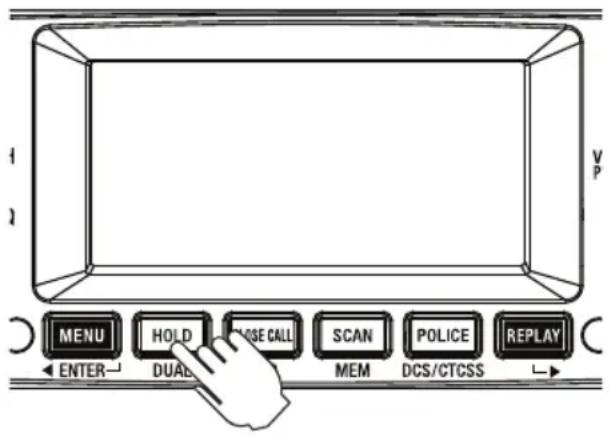
Dual watch will continuously monitor the Instant channel and the current channel for activity (see Programming the Instant Priority Channel, p.20).
Press and hold [DUAL]. DUAL icon appears and two beeps will sound.
To cancel DUAL Watch press and hold [DUAL]. DUAL icon disappears.

- Every 1.5 seconds the Instant channel is monitored for 100msec.
- Dual watch function stops temporarily when receiving a signal.
- Dual watch function is invalid in Scan mode.
Using Repeater Channels
UHF CB repeaters are used to retransmit or relay your signal. Repeaters will extend the range of your radio and overcome the shielding effect caused by solid obstructions. In normal Simplex operation, your radio transmits on one particular frequency and receives on that same frequency.
If there is a barrier that partially blocks your transmitted signal, the probability of another radio receiving the signal is very slim. Hills, tall buildings, metallic structures,...etc tend to act as a screen between radios.
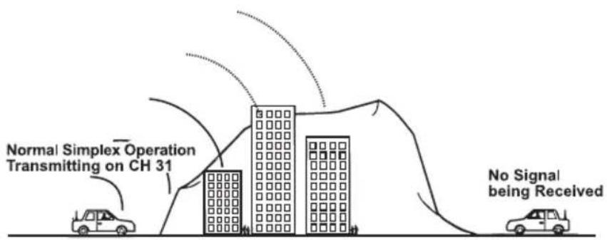
Standard Operation without the aid of a Repeater station.
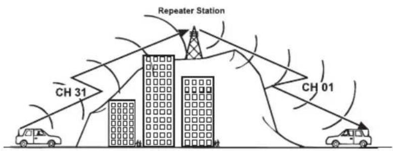
Operation with the aid of a Repeater Station (Duplex).
The signal coming from your radio is received by the Repeater Station and the re-transmitted at the same time on another channel. This operation is called "Duplexing".
For example,
CH01 on Duplex Mode will Receive on CH01 but Transmit on CH31
CH02 on Duplex Mode will Receive on CH02 but Transmit on CH32 etc...
If you transmit on CH01 Duplex mode, you are actually transmitting on CH31 the repeater station down-converts your signal and retransmits on CH01.
Operating the UHF CB Radio in Duplex Mode
For this example we are adopting CH01 as the channel being used in your area for repeater use.
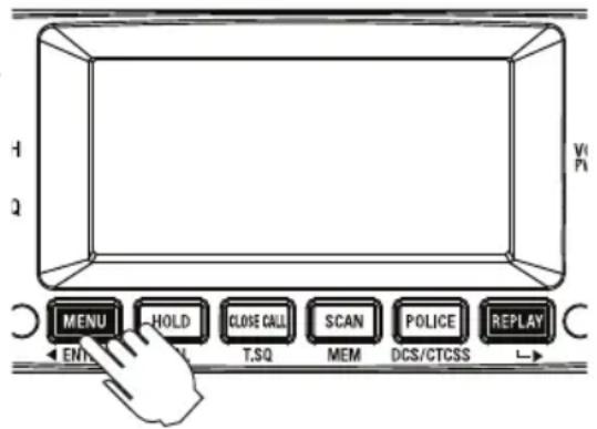
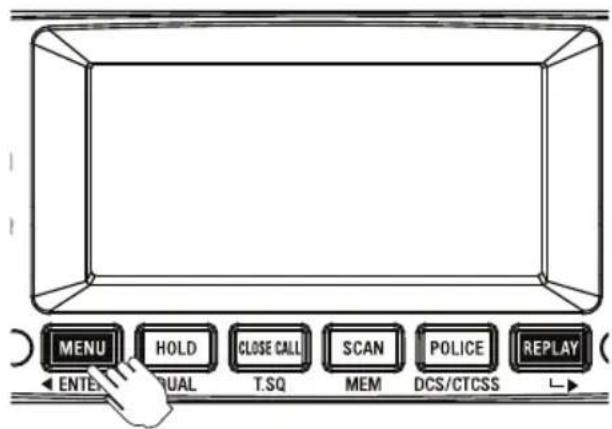
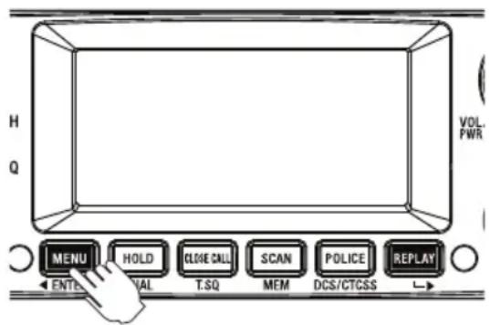
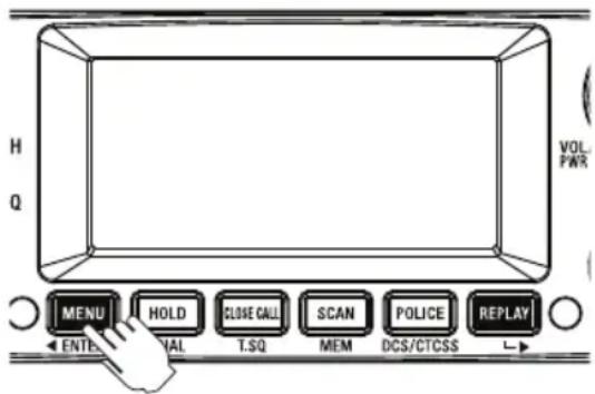
- Press [MENU] on the base. The duplex setting flashes.
- Turn the Rotary Channel Selector on the base to change the setting between ON or OFF (standard channel numbering).
- Press and hold [MENU] to save & exit from the menu mode.
DUP icon displays when a selected channel is set to Duplex mode.

- Only channels 01 - 08, and channels 41 - 48 are available for Duplex.
- Check with your local Retailer for information on available repeaters.
- If a button is not pressed within 10 seconds the UHF CB Radio will automatically exit the Menu Mode.
Scanning
The UH8055S' Scanning feature allows you to search for active channels automatically. There are 3 scanning modes;
Open Scan (OS),
Group Scan (GS) and
Master Scan (M.SCN) (a special case of Group Scan).
During SCAN the UH8055S only checks channels or frequencies that are in the SCAN Memory, which are indicated by the M (memory) icon. The UH8055S maintains two SCAN Memories; one for Open Scan (OS) mode and the other for Group Scan (GS mode, to give you flexibility and allow you to use the radio more effectively.

Group Scan and Master Scan modes share the same SCAN Memory.
Furthermore, any combination of the three channel groups can be scanned by pressing [POLICE] during scan to select the desired channel groups.
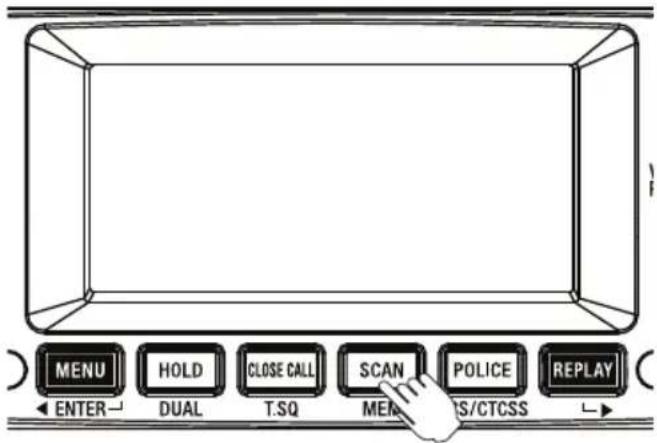
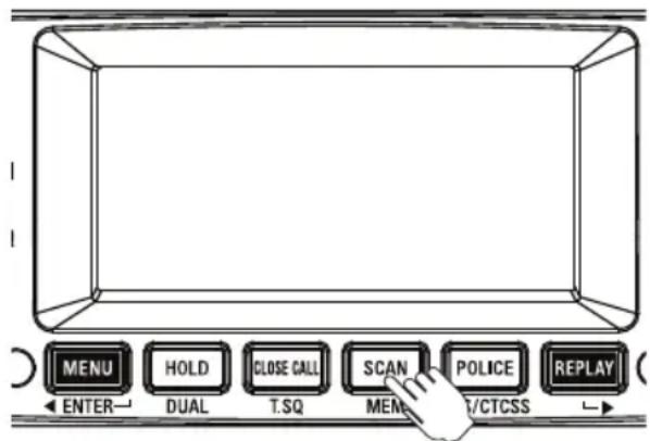
- Press [SCAN] to start Scanning.
- The SCAN icon appears.
- The scan direction can be changed at any time by rotating the Channel knob on the base.
- Press [SCAN] to stop Scanning.
Add/Remove Channels from SCAN Memory
Select OS Scanning Mode. Select the channel you want to store.
Press and hold [MEM]. MEM icon appears and two beep tones sound. To remove the channel from SCAN memory, press and hold [MEM] once more.
The MEM icon disappears.
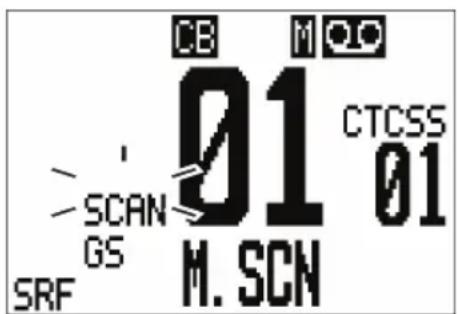
MASTER SCAN Mode
MASTER SCAN is the default scan mode and is enabled to allow continual communication across congested channels.
Master Scan scans channels stored into GS Memory and only opens the squelch for signals with the correct subcode (CTCSS or DCS tone).
To achieve this, all radios in your group must have the same channels in GS memory (group channels) and use the same Subcode (CTCSS or DCS tone).
By scanning only group channels, radios in the network will be able to detect and receive group transmissions- continual communication without interruption. When transmitting in this mode, the radio switches to an unused group channel if it detects another signal with no code, or the wrong code, on the channel last used by the group. In this way, all group users will be able to have continual communication to or from other users.
CH09-CH20 are stored into GS Memory and CTCSS01 is set for MASTER SCAN Subcode by default. The GS memory can be changed, channel by channel, if desired - but for Master Scan to work effectively each radio in the group must have the same channels in its GS memory.
To add/remove channels from GS SCAN Memory, refer the section above.

RX only Channels (CH22, CH23, CH61, CH62 and CH63), User Programmable RX Channels (CH81 to CH180) and Police or Fire (& Ambulance) channels group will not be included in MASTER SCAN Mode even though stored into GS Memory Also channels for which Duplex Setting are On will be skipped in MASTER SCAN Mode.
To select MASTER SCAN Mode:
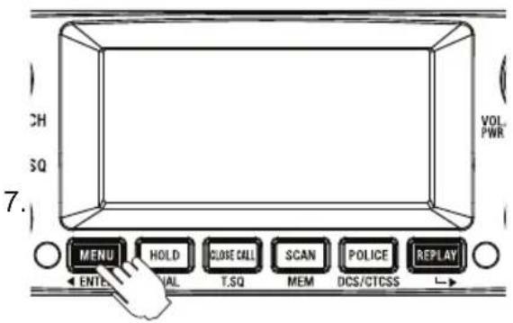
- Press [MENU] four times.
The M.SCAN setting flashes.
- Turn the Rotary Channel Selector to change the setting.
oF: Master Scan is OFF - Scan mode becomes Open Scan or Group Scan depending on GS option setting
on: Master Scan is ON with the current GS channel memory. Open/Group Scan is disabled.
P1: Master Scan is ON with loading CH09-20 in GS.
P2: Master Scan is ON with loading CH21-30, 39, 40 in GS.
P3: Master Scan is ON with loading CH49-60 in GS.
P4: Master Scan is ON with loading CH61-70, 79, 80 in GS.


- Press [MENU] one more time.
- Turn the Rotary Channel Selector to select the desired Subcode (CTCSS or DCS).
- Press and hold the [MENU] to save and exit from the Menu Mode.

If a button is not pressed within 10 seconds the UHF CB Radio will automatically exit the Menu Mode.
Open Scan (OS) Mode
All UHF-CB, user-programmed extra RX channels, Police and Fire & Ambulance frequencies have been added to the OS SCAN Memory for convenience. To add/remove channels from OS SCAN Memory, refer to p.25.
Allows continuous scanning of all selected channels. If an active channel is found, scanning will stop on that channel. If the received signal ceases, the unit will wait 3 seconds for the signal to return, otherwise scanning resumes.
After transmission in scan mode, the unit will wait 20 seconds for the signal to return, otherwise scanning resumes.
To deactivate SCAN, press [SCAN].

NOTE
If SCAN is deactivated while on an active channel, the UH8055S will stay on that active channel. If no channels are active, the UH8055S will reinstate the starting channel.

NOTE
OS Mode is indicated by the absence of the GS icon.
Group Scan (GS) Mode
GS Mode has CH09 to CH20 in the SCAN Memory by default. Channels must be stored to the GS SCAN Memory before group scan can start. To add/remove channels from GS SCAN Memory, refer to p.25.
Includes the accessory feature Priority Watch which allows you to monitor the Instant Priority Channel while scanning (see p.20 for setting Instant Priority Channel and p.29 to turn on Priority Watch).
GS Scanning checks the Instant Priority Channel for activity regularly when Priority Watch is ON.
If the Priority Channel becomes active the radio will stay on that channel for as long as the signal is present. If the received signal ceases, Priority Scanning continues after 3 seconds.
If scanning stops on a channel which is not a Priority Channel, UHF CB Radio will continue monitoring the Priority Channel for activity while listening to the active one.
To select GS Scan Mode:
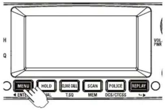
- Press [MENU] three times. The GS setting flashes.
- Turn the Rotary Channel Selector to change the setting between ON and OFF.
- Press and hold [MENU] to save & exit from the menu mode.

NOTE
If a button is not pressed within 10 seconds the UHF CB Radio will automatically exit the Menu Mode.
Priority Watch
To switch Priority Watch On/Off;
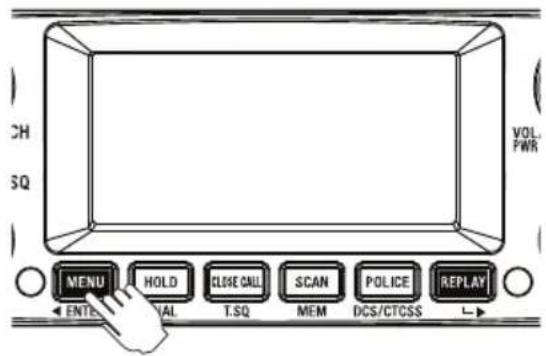
- Press [MENU] two times. The Priority Watch setting flashes.
-
Turn the Rotary Channel Selector to change the setting between ON or OFF.
-
Press and hold [MENU] to save & exit from the menu mode.

If SCAN is deactivated while it is tuned to an active channel, the UH8055S will stay on that active channel. If none of the channels are active, the UH8055S will reinstate the scan start channel.

If OS/GS Scanning is initiated when there are no channels programmed in OS/GS memory, an error tone will be heard and scanning will not start (see Add/Remove Channels from SCAN Memory, p.25).
Selecting the Call Tone (Wake Up Tone)
- Press [MENU] six times. The call tone setting flashes.
- Turn the Rotary Channel Selector to change the setting between 1, 2, 3... 10.
- Press and hold [MENU] to save & exit from the menu mode.

If a button is not pressed within 10 seconds the UHF CB Radio will automatically exit the Menu Mode.
Busy Channel Lockout
If the channel is already in use, you can prevent the UHF CB Radio from transmitting. This is particularly important when using CTCSS/DCS.
- Press [MENU] seven times. The BCL (BUSYLOCK) setting flashes.
-
Turn the Rotary Channel Selector to change the setting between ON or OFF.
-
Press and hold [MENU] to save & exit from the menu mode.

If a button is not pressed within 10 seconds the UH8055S will automatically exit the Menu Mode.
Roger Beep
- Press [MENU] eight times. The roger beep (ROGER) setting flashes.
- Turn the Rotary Channel Selector to change the setting between ON or OFF.
- Press and hold [MENU] to save & exit from the menu mode.

If a button is not pressed within 10 seconds the UH8055S will automatically exit the Menu Mode.
Key Beep On/Off
-
Press [MENU] nine times. The key beep (BEEP) setting flashes.
-
Turn the Rotary Channel Selector to change the setting between OFF, 1, 2, 3... 7.
-
Press and hold [MENU] to save & exit from the menu mode.

If a button is not pressed within 10 seconds the UHF CB Radio will automatically exit the Menu Mode.
Alpha Tag
The SELCALL IDs and Extra Receive Channels have the option of displaying a name (Alpha Tag) instead of the ID or frequency. Set Alpha Tag to ON to display the name if it has been programmed.
-
Press [MENU] ten times. The Alpha Tag (ALPHA) setting flashes.
-
Turn the Rotary Channel Selector to change the setting between ON or OFF.
-
Press and hold [MENU] to save & exit from the menu mode.

If a button is not pressed within 10 seconds the UHF CB Radio will automatically exit the Menu Mode.
Volume Sync
- Press [MENU] 11 times.
The Volume Sync setting flashes.
-
Turn the Rotary Channel Selector at the base or press ▲ / ▼ on the optional Remote SPK/MIC to change the volume sync on/off.
-
Press and hold [MENU] to save & exit from the menu mode.

- When volume sync function is active, the volume of base and optional Remote SPK/MIC are synchronized.
• Volume sync function can be used only when the optional Remote SPK/MIC is connected

If a button is not pressed within 10 seconds the UHF CB Radio will automatically exit the Menu Mode.
Backlight Colour
- Press [MENU] 12 times. The current Backlight colour (CLEAR, BLUE, RED, PURPLE, GREEN, CYAN or YELLOW) setting flashes.
- Turn the Rotary Channel Selector to change the desired colour setting.
- Press and hold [MENU] to save & exit from the menu mode
Backlight Level
- Press [MENU] 13 times. The Backlight level (LIGHT) setting flashes.
- Turn the Rotary Channel Selector to change the setting between OFF, 01, 02 and 03.
- Press and hold [MENU] to save & exit from the menu mode.
LCD Contrast
- Press [MENU] 14 times. The LCD Contrast setting flashes.
- Turn the Rotary Channel Selector to change the setting between 01 (low contrast) to 10 (high contrast).
- Press and hold [MENU] to save & exit from the menu mode.
Simple Mode Setting
Simple Mode is the ability to view a large channel number on the main unit for the UCB Channel (CH01-CH80).
- Press [MENU] 15 times. The Simple mode (SIMPLE) setting flashes.
- Turn the Rotary Channel Selector to change the setting between ON or OFF.
- Press and hold [MENU] to save & exit from the menu mode.

NOTE
If a button is not pressed within 10 seconds the UHF CB Radio will automatically exit the Menu Mode.
100 User Programmable RX Channels
The UH8055S has 100 receive only channels (CH81 to CH180) which can be programmed with frequencies ranging from 400-520MHz (in 12.5kHz steps). The extra RX channels only appear, as part of the CB channel bank, when a frequency has been programmed to a channel. There are three ways to programme RX channels;
- If you know the frequency you may manually programme it to a channel.
- Store a Police or Fire (& Ambulance) frequency to a channel.
- Use the Close Call RF Capture feature to find a nearby strong signal & store this frequency to a channel.
Furthermore, the RX channels can be Alpha Tagged (given a name) if desired.
Manually Programme a RX Channel
In CB channel mode (UHF CB channel);
- Press & hold [MENU]. The lowest available empty RX channel will flash.
-
Turn the Rotary Channel Selector if you wish to select another RX channel.
-
Press [SCAN] to begin the frequency edit. The MHz digit range flashes. Use ◀ or ▶ to shift between MHz range (between 400-520MHz) & kHz range (in 12.5kHz steps). Turn the Rotary Channel Selector to select the desired frequency within MHz & kHz ranges.
-
When desired frequency is entered press [SCAN] to move to Alpha Tag selection. A cursor flashes in the 1st alpha position. If you do not wish to name the channel then skip this step. Turn the Rotary Channel Selector to select the desired alpha character. Use ▶ or ▶ to shift between cursor positions.
-
When finished press [SCAN]. A long confirmation tone sounds to indicate the new channel is programmed. The channel flashes to enable selection for programming of next channel if desired.
-
Press and hold [ENTER], or wait for 10sec, to exit programming mode.
Store a Police or Fire frequency to a RX Channel
Select the Police or Fire (& Ambulance) channels group by pressing [POLICE], and then select a desired frequency by rotating the channel knob.
Or during SCAN, when scan stops on a Police or Fire (& Ambulance) frequency which you wish to store press [HOLD] to stay on that frequency.
- Press and hold [MENU]. The lowest available empty RX channel will appear, alternating with the selected Police and Fire (& Ambulance) frequency.
- Change the RX channel by turning the Rotary Channel Selector
- Press and hold [ENTER]. A confirmation tone sounds to indicate the new channel is programmed.
The RX channel number flashes. - If a name is desired press [SCAN] to begin Alpha Tag edit (see manual programming above).
- Press and hold [ENTER], or wait for 10sec, to exit programming mode.
Store a frequency found using CLOSE CALL to a RX Channel
Start Close Call RF Capture feature.
When an active frequency is found which you wish to store press [HOLD] to stay on that frequency.
- Press and hold [MENU]. The lowest available empty RX channel will appear, alternating with the found frequency.
- Change the RX channel by rotating the channel knob.
- Press and hold [ENTER]. A confirmation tone sounds to indicate the new channel is programmed.
The RX channel number flashes. - If a name is desired press [SCAN] to begin Alpha Tag edit (see manual programming above).
- Press and hold [ENTER], or wait for 10sec, to exit programming mode.
Instant Replay
The Instant Replay feature automatically records up to 1 minute of received signal(s) which can be instantly replayed (through the speaker) by pressing [REPLAY].
Instant Replay automatically records receive signal(s) in the following modes;
• CB & Extra RX channel, Police and Fire (& Ambulance) channel mode
- Scan Mode
- Close Call RF Capture mode
Instant Replay does not record when in monitor mode (SQT-0 setting in normal channel mode).
Press [REPLAY] on the base unit or Speaker MIC at anytime to;
- Playback the most recent received signal. OR
- Playback the most recent recorded signal in the replay buffer (if Instant Replay automatic receive record was turned Off, see Turning Instant Replay On/Off below).
During playback the display shows REPLAY and the number of the currently playing recording.
After the most recent received signal has been played back, a long confirmation tone sounds and the radio returns to the previous mode.
During playback older recordings can be accessed by turning the Rotary Channel Selector or FF/REW on Speaker MIC to skip forward/back between recordings stored within the 1 minute buffer. The record number indicates which discrete recording is currently being replayed.

- Received signals shorter than 500ms are not recorded.
- Automatic recording of receive signal(s) is temporarily suspended during Instant Replay playback.
- Older recordings are automatically overwritten when new recordings are stored.
- Most received communications are short and the 1 minute buffer may contain several recordings.
• Transmissions (TX) are not recorded.
Turning Instant Replay On/Off
Instant Replay is ON by default. The 📄con displays to indicate Instant Replay automatic record is On.
Press and hold [REPLAY] to turn Instant Replay On/Off. Two beep tones sound.
Turn Instant Replay Off if you want to prevent the current 1 minute of recordings from being overwritten.
Close Call™ RF Capture
The Close Call RF Capture feature sets the UH8055S so it detects and then displays the frequency of a nearby strong radio transmission. Close Call RF capture works great for finding frequencies at venues such as malls and sporting events.
Close Call RF Capture doesn't tune to a frequency to check for a transmission, instead it directly detects the presence of a strong, nearby signal and instantly tunes to the source's frequency. The UH8055S only tries to find Close Call transmissions from 400-520 MHz.

- Close Call RF capture works well for locating the source of strong local transmissions such as mobile and handheld two-way radios in areas with no other strong transmission sources. However, if you are in an area with many transmission sources (such as pager radio transmitters, multi-use radio towers, traffic control devices, etc.), Close Call RF capture might not find the transmission you are searching for, or it might find a transmission other than the one you are searching for.
- Close Call works better with some types of transmissions than others. It might not correctly display frequency information for transmitters using a highly directive antenna (such as an amateur radio beam antenna), if there are many transmitters operating at the same time in the same area, or if the transmitter is a broadcast television station.
Using Close Call
To start or stop Close Call RF Capture:
1. Press [CLOSE CALL].
The C-C icon appears and C.CALL is displayed when Close Call RF Capture mode.
When a signal is found a confirmation chirp is sounded and CC FOUND flashes on the display. Press any key (except CLOSE CALL key) when CC FOUND is displayed to show the frequency. The signal strength is also displayed with CC FOUND display.
Lockout an Undesired Frequency
If the signal frequency is undesired (for instance it is a data channel) then the frequency can be added to the lockout list and ignored in future.
- First press [HOLD] to stay on that frequency.
- And then press and hold [HOLD] to lockout that frequency and resume Close Call RF Capture mode.
Unlock a Locked out frequency
- The locked out frequencies can be reviewed by pressing [MENU] while you are in Close Call mode.
LO displays and the lowest frequency in the lockout list flashes.
- Rotate the Channel knob to view other frequencies in the list.
- Press and hold [HOLD] to unlock the currently displayed frequency.
Two beeps sound.
- Press [MENU] to resume Close Call RF Capture mode.

NOTE
- Close Call RF Capture feature is separate to and cannot be operated at the same time as SCAN or normal receive mode.
Selective Calling
Selective Calling (Selcall) is a special Sequential Tone Squelch System that allows the user to receive/transmit calls selectively from/to an individual or group, on a shared busy channel. Therefore Selcall is a group feature used by groups with similarly set up radios.
The UH8055S has a Selective Calling system. Exceptional features, like 10 Selcall ID Memories, Receiver Quieting, Tone Squelch Scanning, Tone and Group Calling make the UH8055S superior to other transceivers in its class.
Receiver Quieting (Tone Squelch)
When activated on individual UHF-CB channels (except for emergency CH05 and CH35), it automatically mutes the receiver audio circuit of the radio. It will stay in this Quiet mode as long as the Selcall tone code (Selcall ID) required to open the muting circuit is not received.
Call Alarm
When a received code matches to your Selcall ID, an alarm (CA Alert) will be emitted informing you that a caller is on the channel.
Tone Squelch Scanning
Scans only tone squelched Channels.
Tone Calling
Allows you to selectively call another radio. Up to 10 Selcall IDs can be stored for frequently called radios.
Group Calling Capability
Transmits Group Calls.
Programming the Selcall ID for your UH8055S
The radio Selcall ID is the ID other users will identify as being your radio. It is set in the Selcall settings menu as follows:
- Power Off the UH8055S.
- Press and hold [POWER] and [MENU]. The UH8055S should turn on in the SELCALL Menu selection state (no tone will sound). Cd displays to indicate the Call ID setting (factory default ID is 00000).
- Press [SCAN] to begin the frequency edit. The 5th digit of the ID flashes.
- Use ◀ or ▶ to shift between digits. A 6th digit (for 6 tone Selcall) is available and indicated by a ‘_’.
- Turn the Rotary Channel Selector to select the desired ID.
- Press and hold [ENTER] to exit the setting mode.
- Press and hold [ENTER] again to exit programming mode. A long confirmation tone sounds.
Storing Selcall IDs of other users to the ID Memory
- Press and hold [CALL/SELCALL]. The Selcall ID memory will open.
- Turn the Rotary Channel Selector to select the desired memory slot to edit.

- Up to 10 ID memories can be stored.
-
If you expect to make calls to radios not stored in the ID memory then leave memory ID 1 blank for manual ID entry at the time of the call.
-
Press [SCAN] to begin the ID edit. The 5th digit of the ID flashes.
-
Use ◀ or ▶ to shift between digits. A 6th digit (for 6 tone Selcall) is available and indicated by a ‘_’.
-
Turn the Rotary Channel Selector to select the desired ID.
-
When desired ID is entered press [SCAN] to move to Alpha Tag selection. A cursor flashes in the 1st alpha position. The default aplha tag is blank - displays as No Name. If you do not wish to name the ID then skip to step 9.
-
Turn the Rotary Channel Selector to select the desired alpha character.
-
Use ◀ or ▶ to shift between cursor positions.
-
When finished press [SCAN]. A confirmation tone sounds to indicate the ID is programmed. The memory number flashes to enable selection for programming of next memory if desired.
-
Press and hold [ENTER], or wait for 10sec, to exit programming mode.
Tone Calling (Making a Selcall Call)
Tone Calling allows you to selectively call other radios.
For convenience, the Selcall ID of the radio you are going to call should be in the Selcall ID memory (see Storing Selcall IDs of other users to the ID Memory p.40). If not then the Selcall ID can be manually entered for this call.
To Call:
- Select the channel that you and your group agreed to use for Selective Calling.
- Press and hold [CALL/SELCALL] for 2 seconds. A double beep tone will sound and the last stored ID or last transmitted ID will be displayed.
- Turn the Rotary Channel Selector to select the desired Selcall ID.
If the desired Selcall ID is not stored in the ID memory you can manually enter the ID as follows;
a) Press [SCAN] to begin ID edit. The 5th digit of the ID flashes.
b) Use ◀ or ▶ to shift between digits. A 6th digit (for 6 tone Selcall) is available and indicated by a ‘_’.
c) Turn the Rotary Channel Selector to select the desired ID.
- Press [CALL/SELCALL] to transmit the Selcall. CAL will display when transmitting the Selcall.
An acknowledge tone coming from the called radio will be received if you have successfully made contact. The acknowledge tone for the UH8055S is a succession of three low tone beeps.
Receiver Quiet (TSQ) Mode
Puts the receiver in the QUIET mode (also known as the Tone Squelch (TSQ) mode) for the selected channel. When activated, the transceiver prevents any unwanted conversations in the channel from being heard unless the call is specifically directed to you and the Selcall ID required to open the QUIET condition has been received.

Under this condition, PTT is temporarily disabled. If you wish to use the same Channel for normal communication, simply remove the channel from QUIET mode.
To Activate/Deactivate Tone Squelch (TSQ) on a Channel
- Rotate the Channel knob to select the channel you want to put in or take out of 'QUIET' mode.
- Press and hold [TSQ] for 2 seconds. Two beeps will sound and the TSQ icon appears on or disappears from the LCD display.
Receiving a Selcall
While in TSQ mode, when UH8055S receives a code matching your Selcall ID, it will perform the following operations:
a) Automatically responds to the caller by transmitting Acknowledge Tones.
b) Informs you that a caller is on the Channel by emitting a CALL ALARM (Default Alarm Setting: four successive beeps in a regular interval for 10 seconds. Refer to p.40, 'Alarm Mode' for other alarm settings) and displays the CAL icon.
c) Flashes the TSQ icon for about 20 seconds allowing you to use the PTT button. If you are not able to respond within the 20 second period, TSQ icon stops flashing and 'QUIET' mode resumes.

The UH8055S can decode a Selcall call even though not in 'QUIET' mode.
Scanning Tone Squelched Channels
If you are using two or more Channels in the TSQ mode, you can monitor all of these Channels for selective calls by using the TSQ scanning feature.
To use this feature start the TSQ Scan by pressing and holding [TSQ] for 2 seconds during Open Scan or Group Scan.
Unlike Normal Scanning, TSQ scans and checks detected signals for Selcall information. If this information is not found, TSQ Scanning resumes.
When a call is received during TSQ Scanning, UH8055S follows the same response as when receiving a call on a Tone Squelch Channel. It differs only in the following ways:
- If the call is not answered within 20 seconds, TSQ Scanning resumes.
The CAL icon remains on the LCD display.
To look for the Channel where the CALL is received.
a) Cancel TSQ Scanning by pressing [SCAN].
b) Turn the Rotary Channel Selector to browse through the TSQ Channels. The CAL indicator marks the Channel where the Call is received.
- When answered, TSQ Scanning is automatically deactivated. The Channel is removed from the QUIET Operating Mode.
To deactivate TSQ Scanning:
a) Press and hold [TSQ] for 2 seconds.
The unit returns to Normal Scanning Mode.
b) Press [SCAN].
The whole scanning operation is cleared.
c) When a Selcall is received, press PTT.

NOTE
The chance of receiving and decoding Selcalls effectively during TSQ Scanning can be increased in many different ways. You can either decrease the number of channels to be scanned thus increasing the scanning speed – or – change some of the Selcall parameters (refer to 'Selcall Programming').
Group Calling
The UH8055S has the capability to respond to Group Calling and to transmit Group Calling Codes.
Group Calling allows you to call members of your group simultaneously. However, to do this, you need to follow a certain format (see below) when programming your TX Selcall ID.
Selcall ID Format
To call Transmitter SELCALL ID
10 radios [X] [X] [X] [X] [A]
100 radios [X] [X] [X] [A] [A]
1000 radios [X] [X] [A] [A] [A]
where: [X] is a common Selcall ID prefix of your group
- and - [A] is the CCIR Assigned Group Tone Code
Example:
If one group comprises 10 members with Selcall IDs the ID numbers could be as follows:
Group ID # Individual ID#
[1] [2] [3] [4] [0]
[1] [2] [3] [4] [1]
[1] [2] [3] [4] [2]
[1] [2] [3] [4] [3]
to -
[1] [2] [3] [4] [9]
all in TSQ mode at CH20
If someone transmits ID 1234A on CH20, all of the above units will open their Tone Squelched Receiver.
Group Calls and ordinary Selcalls can be differentiated in the following manner:
Group Call - Low tone beeps
Ordinary Selcall - High tone beeps
SELCALL Settings
Tone Period
Tone period is the duration of one tone in a Selcall ID sequence. The setting of this parameter depends on the type of application. On long distance communications, for example: where the signal strength of the transmitted information is greatly reduced and affected by noise, it is advisable to use a longer Tone Period. A long Tone Period gives the decoder more time and information to check and evaluate the code.

However, be sure that all the radios in your group use the same Tone Period setting. Otherwise you will not be able to selectively call one another.
The UH8055S allows you to select which Tone Period is best for you. The three most commonly used tone settings (40,70 or 100 mSec) are available. With the freedom to change this parameter, you can easily adapt to the existing system in your group without the inconvenience of having the unit serviced by the dealer.
- Power Off the UH8055S.
- Press and hold [POWER] and [MENU]. The SELCALL Settings Menu will display (no tone will sound).
- Press [MENU] repeatedly to select the Tone Period setting - which is indicated on the display as Pd.
- Press [SCAN] to edit the setting. The current setting flashes.
- Turn the Rotary Channel Selector to select the desired tone period from 40ms, 70ms or 100ms.
- Press [SCAN] to exit the setting.
- Press and hold [ENTER], to save and exit programming mode.
Lead-in Delay
Lead-in delay is a Selcall transmission parameter that ‘wakes-up’ and helps the receiver of the other radio to lock onto the incoming signal. Each time a Selcall ID is transmitted, the Lead-in Delay attaches itself to the beginning of the code sequence and causes the transmitter to be on for a longer period prior to the code transmission. This makes for a stronger communication link between the transmitter and the other receiver.
One major advantage to having the longer Lead-in Delay is when selectively calling another radio via a repeater station. A longer Lead-in Delay helps to stabilise both the communication link from your radio to the repeater station and from the repeater station to the other radio.
Lead-in Delay Programming
- Power Off the UH8055S.
- Press and hold [POWER] and [MENU]. The SELCALL Settings Menu will display (no tone will sound).
- Press [MENU] repeatedly to select the Lead-in Delay setting - which is indicated on the display as Ld.
- Press [SCAN] to edit the setting. The current setting flashes.
- Turn the Rotary Channel Selector to select the desired Lead-in delay period from 500ms, 1000ms, 2000ms, 3000ms or 4000ms.
- Press [SCAN] to exit the setting.
- Press and hold [ENTER], to save and exit programming mode.
Lead-in Tone
The Lead-in Tone, when programmed, 'rides' on the Lead-in Delay.
Hence, when transmitting a Selcall ID, a continuous tone will be heard for the duration of the Lead-in Delay. The main purpose of the Lead-in Tone is to increase the probability of contact between your unit and another radio when TSQ Scanning.
- Power Off the UH8055S.
- Press and hold [POWER] and [MENU]. The SELCALL Settings Menu will display (no tone will sound).
- Press [MENU] repeatedly to select the Lead-in Tone setting - which is indicated on the display as LT.
- Press [SCAN] to edit the setting. The current setting flashes.
- Turn the Rotary Channel Selector to select the desired Lead-in Tone.

- If you want to remove the Lead-in Tone choose the space [ _ ] Bar.
- Press [SCAN] to exit the setting.
- Press and hold [ENTER], to save and exit programming mode.
Alarm Mode
When a received code matches to your receiver Selcall ID the UH8055S will respond based on the Call Alarm mode.
Call Alarm - Auto mode (Default)
a) Transmit an Acknowledge tone to the Caller.
b) Emit CALL Alarm for 10 seconds only.
c) Resume Quiet condition automatically after 20 seconds if the call is not answered.
d) The Unit will start decoding again when the 20 second period elapsed and the call remained unanswered.
Call Alarm - Continue mode
a) Transmit an Acknowledge Tone to the Caller.
b) Initially an alarm of four successive beeps is emitted for 20 seconds and then two successive beeps every four seconds continuously unless answered.
c) The Quiet Condition is never resumed.
d) The Unit continues to check if incoming codes have your Receiver Selcall ID even though the Quiet Condition is already opened. When detected, it will send an acknowledge Tone to the caller and then resets the Call Alarm.

NOTE
For both of the above mentioned modes, transmission by using the PTT button is possible when the TSQ icon is flashing.
- Power Off the UH8055S.
- Press and hold [POWER] and [MENU]. The SELCALL Settings Menu will display (no tone will sound).
- Press [MENU] repeatedly to select the Alarm mode setting - which is indicated on the display as AL.
- Press [SCAN] to edit the setting. The current setting flashes.
- Turn the Rotary Channel Selector to select the desired Alarm mode from AUTO or CONT.
- Press [SCAN] to exit the setting.
- Press and hold [ENTER], to save and exit programming mode.
Group Call Mode
The Group Tone period can be adjusted to increase the ability to identify group calls. Group 01 mode sets the tone period to 1 tone period (default). Group 02 mode sets the first group tone period to 3 tone periods.
- Power Off the UH8055S.
- Press and hold [POWER] and [MENU]. The SELCALL Settings Menu will display (no tone will sound).
- Press [MENU] repeatedly to select the Group Call mode setting - which is indicated on the display as GROUP.
- Press [SCAN] to edit the setting. The current setting flashes.
- Turn the Channel knob to select the desired Group Call mode from 01 or 02.
- Press [SCAN] to exit the setting.
- Press and hold [ENTER], to save and exit programming mode.
SELCALL Tone Frequency List
| Tone No. | Tone Frequency (Hz) | Tone No. | Tone Frequency (Hz) |
| 0 1981 8 | 1747 | ||
| 1 1124 9 | 1860 | ||
| 2 1197 A | (Group) 2400 | ||
| 3 1275 B | 930 | ||
| 4 1358 | C | 2247 | |
| 5 1446 | D | 991 | |
| 6 1540 | E (Repeat) | 2110 | |
| 7 1640 F | 1055 |
CTCSS Codes Table
| Code No. | Frequency (Hz) | Code No. | Frequency (Hz) | |
| “oF” OFF | 20 | 131.8 | ||
| 1 | 67.0 | 21 | 136.5 | |
| 2 | 71.9 | 22 | 141.3 | |
| 3 | 74.4 | 23 | 146.2 | |
| 4 | 77.0 | 24 | 151.4 | |
| 5 | 79.7 | 25 | 156.7 | |
| 6 | 82.5 | 26 | 162.2 | |
| 7 | 85.4 | 27 | 167.9 | |
| 8 | 88.5 | 28 | 173.8 | |
| 9 | 91.5 | 29 | 179.9 | |
| 10 | 94.8 | 30 | 186.2 | |
| 11 | 97.4 | 31 | 192.8 | |
| 12 | 100.0 | 32 | 203.5 | |
| 13 | 103.5 | 33 | 210.7 | |
| 14 | 107.2 | 34 | 218.1 | |
| 15 | 110.9 | 35 | 225.7 | |
| 16 | 114.8 | 36 | 233.6 | |
| 17 | 118.8 | 37 | 241.8 | |
| 18 | 123.0 | 38 | 250.3 | |
| 19 | 127.3 |
| Code No. | DCS Code (Octal) | Code No. | DCS Code (Octal) | Code No. | DCS Code (Octal) |
| 1 023 36 | 223 71 445 | ||||
| 2 025 37 | 225 72 446 | ||||
| 3 026 38 | 226 73 452 | ||||
| 4 031 39 | 243 74 454 | ||||
| 5 032 40 | 244 75 455 | ||||
| 6 036 41 | 245 76 462 | ||||
| 7 043 42 | 246 77 464 | ||||
| 8 047 43 | 251 78 465 | ||||
| 9 051 44 | 252 79 466 | ||||
| 10 053 45 | 255 80 503 | ||||
| 11 054 46 | 261 81 506 | ||||
| 12 065 47 | 263 82 516 | ||||
| 13 071 48 | 265 83 523 | ||||
| 14 072 49 | 266 84 526 | ||||
| 15 073 50 | 271 85 532 | ||||
| 16 074 51 | 274 86 546 | ||||
| 17 114 52 | 306 87 565 | ||||
| 18 115 53 | 311 88 606 | ||||
| 19 116 54 | 315 89 612 | ||||
| 20 122 55 | 325 90 624 | ||||
| 21 125 56 | 331 91 627 | ||||
| 22 131 57 | 332 92 631 | ||||
| 23 132 58 | 343 93 632 | ||||
| 24 134 59 | 346 94 654 | ||||
| 25 143 60 | 351 95 662 | ||||
| 26 145 61 | 356 96 664 | ||||
| 27 152 62 | 364 97 703 | ||||
| 28 155 63 | 365 98 712 | ||||
| 29 156 64 | 371 99 723 | ||||
| 30 162 65 | 411 100 731 | ||||
| 31 165 66 | 412 101 732 | ||||
| 32 172 67 | 413 102 734 | ||||
| 33 174 68 | 423 103 743 | ||||
| 34 205 69 | 431 104 754 | ||||
| 35 212 70 | 432 |

Always listen on a channel (or observe the receive signal level meter) to ensure it is not already being used before transmitting.
Channels 5 and 35 are used for emergency channels.
CTCSS, DCS, TSQ and SELCALL will not operate on these channels.
Please follow these guidelines for channel use in Australia:
- Channels 05 and 35 are Emergency Channels.
• Channel 11 is a Calling Channel. - Channels 22 and 23 are for telemetry and telecommand applications, channels 61, 62 and 63 are for future use and TX is inhibited on these channels.
General communication is accepted on all other channels with these guidelines:
- Channel 40 - road channel (Australia).
- Channels 01-08 (and 31-38), and Channels 41-48 (and 71-78) are repeater channels.

Important information - 80 Channel UHF-CB channel expansion
To provide all users additional channel capacity within the UHF-CB Band. The ACMA will change the majority of the current wideband 40 channel use to narrowband channel use. This allows for additional channels to be added, up to 80 Channels.
This simply means that the new narrowband radio you have purchased will have more channels than older radios. Please refer to the guidelines above and the channel chart for further channel information.
A list of currently authorised channels can also be obtained from the ACMA website in Australia and the MBIE website in New Zealand.
Interference / Poor Audio
When a new narrowband radio receives a signal from an older wideband radio the speech may sound loud - however the radio's built-in AVS (Automatic Volume Stabilizer) circuitry will detect and manage incoming audio to comparable levels.
Narrowband radios operating on CH41 - CH80 may encounter interference from a nearby wideband radios transmitting on high power on an adjacent channel (frequency).
When an older wideband radio receives a signal from a new narrowband radio the speech may sound quiet - the wideband radio user simply adjusts their radio volume for best performance.
The above situations are not a fault of the radio but a symptom of mixed wideband and narrowband radios in current use. It is expected that as older wideband radios are phased out this issue will be eliminated.
UHF-CB Channels and Frequencies
| CH No. | Simplex Mode Transmit / Receive Frequency (MHz) | Duplex Mode Transmit Frequency (MHz) | CH No. | Simplex Mode Transmit / Receive Frequency (MHz) |
| 1 476 | 425 477.175 (CH31) | 21 476.925 | ||
| 2 476 | 450 477.200 (CH32) | 22 476.950 (RX only) | ||
| 3 476 | 475 477.225 (CH33) | 23 476.975 (RX only) | ||
| 4 476 | 500 477.250 (CH34) | 24 477.000 | ||
| 5 476 | 525 477.275 (CH35) | 25 477.025 | ||
| 6 476 | 550 477.300 (CH36) | 26 477.050 | ||
| 7 476 | 575 477.325 (CH37) | 27 477.075 | ||
| 8 476 | 600 477.350 (CH38) | 28 477.100 | ||
| 9 476 | 625 29 477.125 | |||
| 10 476 | 650 30 477.150 | |||
| 11 476 | 675 31 477.175 | |||
| 12 476 | 700 32 477.200 | |||
| 13 476 | 725 33 477.225 | |||
| 14 476 | 750 34 477.250 | |||
| 15 476 | 775 35 477.275 | |||
| 16 476 | 800 36 477.300 | |||
| 17 476 | 825 37 477.325 | |||
| 18 476 | 850 38 477.350 | |||
| 19 476 | 875 39 477.375 | |||
| 20 476 | 900 40 477.400 |
UHF-CB Channels and Frequencies
| CH No. | Simplex Mode Transmit / Receive Frequency (MHz) | Duplex Mode Transmit Frequency (MHz) | CH No. | Simplex Mode Transmit / Receive Frequency (MHz) |
| 41 476.4375 477.1875 (CH 71) 61 | future use476.9375 (RX only) | |||
| 42 476.4625 477.2125 (CH 72) 62 | future use476.9625 (RX only) | |||
| 43 476.4875 477.2375 (CH 73) 63 | future use476.9875 (RX only) | |||
| 44 476.5125 477.2625 (CH 74) 64 477.0125 | ||||
| 45 476.5375 477.2875 (CH 75) 65 477.0375 | ||||
| 46 476.5625 477.3125 (CH 76) 66 477.0625 | ||||
| 47 476.5875 477.3375 (CH 77) 67 477.0875 | ||||
| 48 476.6125 477.3625 (CH 78) 68 477.1125 | ||||
| 49 476.6375 69 477.1375 | ||||
| 50 476.6625 70 477.1625 | ||||
| 51 476.6875 71 477.1875 | ||||
| 52 476.7125 72 477.2125 | ||||
| 53 476.7375 73 477.2375 | ||||
| 54 476.7625 74 477.2625 | ||||
| 55 476.7875 75 477.2875 | ||||
| 56 476.8125 76 477.3125 | ||||
| 57 476.8375 77 477.3375 | ||||
| 58 476.8625 78 477.3625 | ||||
| 59 476.8875 79 477.3875 | ||||
| 60 476.9125 80 477.4125 | ||||
UNIDEN UH8055S UHF CB Transceiver
IMPORTANT: Satisfactory evidence of the original purchase is required for warranty service
Please refer to our Uniden website for any details or warranty durations offered in addition to those contained below.
Warrantor: The warrantor is Uniden Australia Pty Limited ABN 58 001 865 498 ("Uniden Aust").
Terms of Warranty: Uniden Aust warrants to the original retail purchaser only that the UH8055S UHF CB Transceiver (“the Product”), will be free from defects in materials and craftsmanship for the duration of the warranty period, subject to the limitations and exclusions set out below.
Warranty period: This warranty to the original retail purchaser is only valid in the original country of purchase for a Product first purchased either in Australia or New Zealand.
| Product 5 Years | |
| Battery Pack & Accessories | 1 Year |
If a warranty claim is made, this warranty will not apply if the Product is found by Uniden to be:
(A) Damaged or not maintained in a reasonable manner or as recommended in the relevant Uniden Owner's Manual;
(B) Modified, altered or used as part of any conversion kits, subassemblies or any configurations not sold by Uniden Aust;
(C) Improperly installed contrary to instructions contained in the relevant Owner's Manual
(D) Repaired by someone other than an authorized Uniden Repair Agent in relation to a defect or malfunction covered by this warranty; or
(E) Used in conjunction with any equipment, parts or a system not manufactured by Uniden.
Parts Covered: This warranty covers the Product and included accessories.
User-generated Data: This warranty does not cover any claimed loss of or damage to user-generated data (including but without limitation phone numbers, addresses and images) that may be stored on your Product.
Statement of Remedy: If the Product is found not to conform to this warranty as stated above, the Warrantor, at its discretion, will either repair the defect or replace the Product without any charge for parts or service. This warranty does not include any reimbursement or payment of any consequential damages claimed to arise from a Product's failure to comply with the warranty.
Our goods come with guarantees that cannot be excluded under the Australian Consumer Law. You are entitled to a replacement or refund for a major failure and for compensation for any other reasonably foreseeable loss or damage. You are also entitled to have the goods repaired or replaced if the goods fail to be of acceptable quality and the failure does not amount to a major failure.
This warranty is in addition to and sits alongside your rights under either the COMPETITION AND CONSUMER ACT 2010 (Australia) or the CONSUMER GUARANTEES ACT (New Zealand) as the case may be, none of which can be excluded.
Procedure for obtaining warranty service: Depending on the country in which the Product was first purchased, if you believe that your Product does not conform with this warranty, you should deliver the Product, together with satisfactory evidence of your original purchase (such as a legible copy of the sales docket) to Uniden at the address shown below. You should contact Uniden regarding any compensation that may be payable for your expenses incurred in making a warranty claim. Prior to delivery, we recommend that you make a backup copy of any phone numbers, images or other data stored on your Product, in case it is lost or damaged during warranty service.
UNIDEN AUSTRALIA PTY LTD
Service Division
345 Princes Highway,
Rockdale, NSW 2216
Phone: 1300 366 895
Email: custservice@uniden.com.au
THANK YOU FOR BUYING A UNIDEN PRODUCT.
Uniden®
© 2015 Uniden Australia Pty Limited. Printed in Vietnam. U01UT960AZZ(0)