500760-KVM - Controller MuxLab - Free user manual and instructions
Find the device manual for free 500760-KVM MuxLab in PDF.


| Product Type | Network Controller (AV over IP Management) |
| Model | 500760-KVM |
| CPU | Intel Z3735F |
| Memory | 2GB DDR3 |
| Operating System | Ubuntu 15.04 |
| Video Output | VGA (up to 1920x1200) and HDMI |
| Audio | 3.5 mm audio in and out |
| Network Interface | 1x RJ-45 Ethernet (10/100/1000) |
| USB Ports | 3x USB 2.0 |
| Storage Expansion | 1x microSD slot |
| Power Supply | External power adapter (included), DC 5V |
| Dimensions | 4.52 x 4.52 x 1.4 inches (115 x 115 x 35 mm) |
| Weight | 1.1 lbs (0.5 kg) |
| Operating Temperature | 5 °C to 50 °C |
| Wireless | Wi-Fi antenna (for mobile control) |
| Management Interface | Web interface (HTTP) and mobile interface |
| Protocol Support | HTTP POST with JSON API |
| Compatible Devices | MuxLab AV over IP extenders (500752, 500753, etc.) |
| Matrix Switching | Supports connection and preset management |
| Security | Kensington lock slot for physical security |
| Regulatory Certifications | FCC, CE, RoHS, WEEE |
| Warranty | See product warranty policy (standard 3 months) |
Frequently Asked Questions - 500760-KVM MuxLab
User questions about 500760-KVM MuxLab
0 question about this device. Answer the ones you know or ask your own.
Ask a new question about this device
Download the instructions for your Controller in PDF format for free! Find your manual 500760-KVM - MuxLab and take your electronic device back in hand. On this page are published all the documents necessary for the use of your device. 500760-KVM by MuxLab.
USER MANUAL 500760-KVM MuxLab
MuxLab Pro Digital Network Controller (MNC)
(Model: 500811)

natural_image
Two black wireless network devices, MuxLab PRODIGITAL and MuxLab PRODIGITAL PRODIGITAL, shown side by side with antennas and ports (no visible text beyond branding)Operation Manual
Copyright Notice:
Copyright © 2014 MuxLab Inc. All rights reserved.
Printed in Canada. No part of this publication may be reproduced, stored in a retrieval system, or transmitted in any form or by any means, electronic, mechanical, photocopying, recording or otherwise without prior written permission of the author.
Trademarks:
MuxLab is a registered trademark of MuxLab Inc.
Table of Contents
1. Overview....4
1.1.Description....4
1.2. Features....5
2. Technical Specifications ....6
3. Installation and Use ....7
3.1. Part List....7
3.2. Product Overview 8
3.3. Installation Procedure 9
3.4. Ethernet Web Interface – Device Management 23
3.5. Mobile Interface....34
4. Troubleshooting....38
5. Appendix....39
A. IP Commands....39
6. Product Warranty Policy ....46

1.1. Description
The MuxLab Pro Digital Network Controller is a Linux-based PC that allows users to control hub-installed MuxLab products.
When installed on a local area network (LAN), the MuxLab Pro Digital Network Controller can scan the LAN for MuxLab products and allows the user to configure and control these products through an Ethernet Web interface.
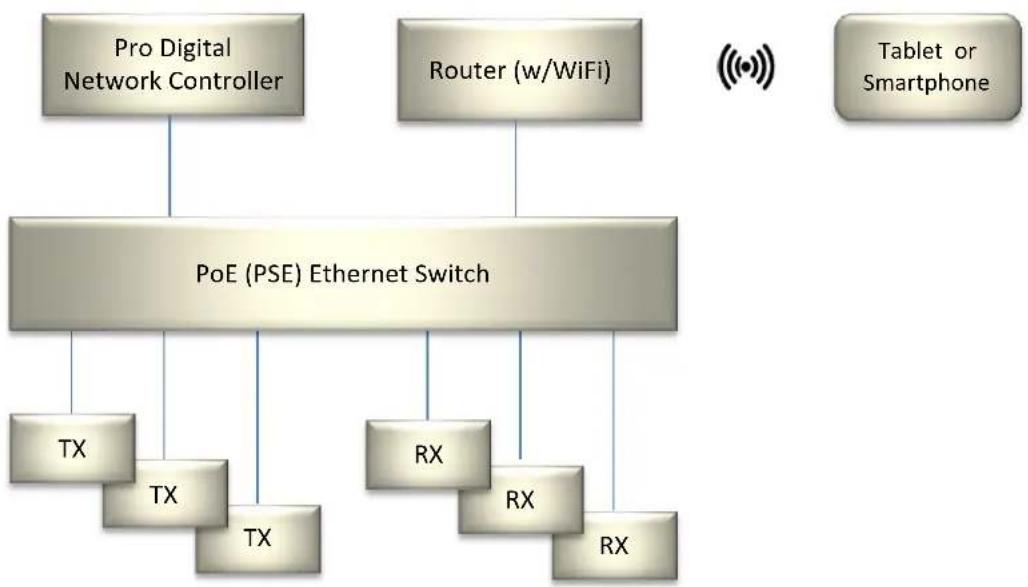
flowchart
graph TD
    A["Pro Digital Network Controller"] --> B["PoE (PSE) Ethernet Switch"]
    C["Router (w/WiFi)"] --> B
    D["Tablet or Smartphone"] --> B
    B --> E["TX"]
    B --> F["TX"]
    B --> G["TX"]
    B --> H["RX"]
    B --> I["RX"]
    B --> J["RX"]
Figure 1: System Overview
Applications include but are not limited to commercial and residential AV systems, classroom projector systems, digital signage, video wall systems, boardroom systems, multi-room systems, classroom training, retail systems, collaborative PC systems, and medical information systems.
1.2. Features

natural_image
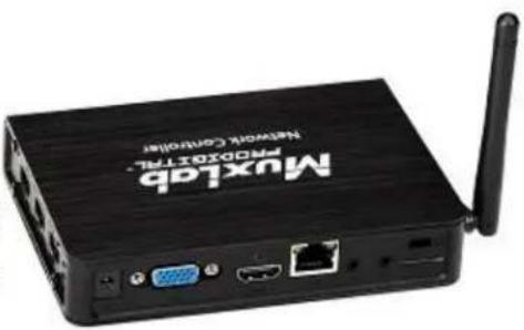
Black MuxLab PRODIGITAL Network Controller device with wireless antenna (no visible text or symbols beyond branding)(Front View)
natural_image
Black wireless router with network controller and port (no visible text or symbols beyond branding)(Rear & Side View)
Figure 1: Pro Digital Network Controller
Front Panel
- Power LED
- Power button
Back Panel
- VGA video port
- HDMI video port
• LAN port (RJ-45 jack) - Audio in (3.5 mm)
• Audio out (3.5 mm) - Micro SD memory slot
- K lock
- Power connector
Side Panel
• Three (3) USB 2.0 ports
2. Technical Specifications
| MuxLab ProDigital Network Controller | |
| CPU | Intel Z3735F |
| Memory | 2GB DDR3 |
| BIOS | AMI BIOS |
| VGA | Resolution up to 1920 x 1200 |
| Keyboard and Mouse | USB keyboard and mouse (sold separately) |
| Peripherals | • USB 2.0 ports (3x)• micro SD slot (1x)• Network interface (1x)• Audio in and out |
| Operating System | Ubuntu 15.04 |
| Operating Temperature | 5 °C to 50 °C |
| Dimensions | 4.52 x 4.52 x 1.4 inch (115 x 115 x 35 mm) |
| Weight | 1.1lbs (0.5kg) |
| Accessories Included | External Power Adaptor |
| Regulatory | FCC, CE, RoHS, WEEE |
| Order Information | 500811 Pro Digital Network Controller |
Table 1: Technical Specifications
3. Installation and Use
3.1. Part List
The MuxLab Pro Digital Network Controller comes with the following parts:
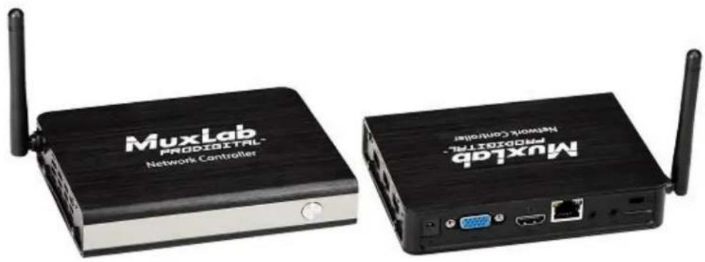
- Base unit (1x)
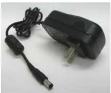
• External Power Adapter (1x)
natural_image
Two black wireless network devices, MuxLab PRODIGITAL and MuxLab PRODIGITAL PRODIGITAL, shown with antennas and ports (no readable text beyond branding)Please verify that both parts are present before proceeding.
Figure 2: Base Unit
natural_image
Black and white photo of a handheld electronic device with cable and connector (no visible text or symbols)Figure 3: External Power Adaptor
3.2. Product Overview
The external connections and connection indicators of the MuxLab Pro Digital Network Controller are detailed in
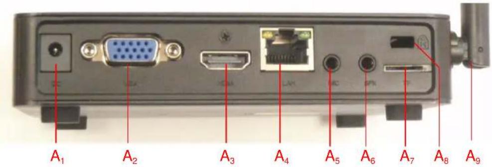
Figure 4: Rear Panel and Figure 5: Side Panel. Please familiarize yourself with them before installing the unit.

Figure 4: Rear Panel
A_1=DC Power
A_2=VGA video
A_3=HDMI video
A_4 = RJ45 Ethernet
A_5 = Audio in
A_6 = Audio out
A_7 = Micro SD Memory Slot
A8 = K Lock
A9 = Wifi antenna

Figure 5: Side Panel
B_1=USB2.0#1
B_2 = USB 2.0 #2
B_3=USB2.0#3
3.3. Installation Procedure
Note that the examples below assume that the Ethernet Switch used does not support WiFi, and a Router with WiFi capability is required in order to communicate with smartphones and tablets for control purposes.
Setting the Ethernet Switch & Router to the same Subnet as MuxLab Devices:
The MuxLab Pro Digital Network Controller comes with a default static IP address of 192.168.168.50 (with DHCP disabled). The MuxLab AV over IP Transmitters and Receivers are set to support DHCP by default. When no DHCP server is available the AV over IP Transmitters and Receivers fallback to a static IP address of 192.168.168.55 (for the 500752, 500753, 500754 and 500756 Transmitters) and 192.168.168.56 (for the 500752, 500753, 500754 and 500756 Receivers), and 192.168.168.58 (for the 500758 and 500759 Transmitters) and 192.168.168.59 (for the 500758 and 500759 Receivers).
These MuxLab products (MNC, and the AV over IP Transmitters & Receivers) work in conjunction with a PoE (PSE) Ethernet Switch (MuxLab recommends the Cisco SG300 Series) and a Router of your choice with WiFi capability to be able to communicate with a smartphone or tablet. The use of a smartphone or tablet to manage the MuxLab devices with third party software applications is optional but is the most common method of control and generally preferred, however MuxLab devices may also be managed via the Pro Digital Network Controller web interface.
In order for the DHCP server within the Ethernet Switch to support the MuxLab device subnet, set the static IP of the Ethernet Switch to 192.168.168.1 (recommended setting). Refer to the Ethernet Switch manual for instructions on how to accomplish this. MuxLab also has a guide specific to the Cisco SG300 Series, see document SE-000819-A (Configuring Network Setting of the Ethernet Switch & MuxLab AV over
IP Devices), which can be found on MuxLab's website under any of the AV over IP product pages (as a download under the Operation Manual sub-category).
The Router with WiFi capability, must also be placed on the same subnet as the MuxLab devices and it should be set with a Static IP address, we recommend using a Static IP address of 192.168.168.2. Refer to your Router documentation on how to accomplish this.
Setting MuxLab Devices, Ethernet Switch and Router to an Existing Subnet:
If the MuxLab AV over IP devices are being installed in an existing environment that has a working subnet already configured that cannot be easily changed, then the subnet of the MuxLab devices, the Ethernet Switch (if a new Ethernet Switch is required), and the Router with Wifi (if a new Router is required) must be changed in order to match the existing subnet. For this case we will use 192.168.2.x as an example subnet already in place and which must be supported. Note that this is only an example and may not necessarily reflect your actual subnet address.
If the Ethernet Switch does not already reside in the example subnet of 192.168.2.x, then set the static IP of the Ethernet Switch to a free static IP address (for the sake of this example we will use an IP address of 192.168.2.1). Refer to the Ethernet Switch manual for instructions on how to accomplish this. MuxLab also has a guide specific to the Cisco SG300 Series, see document SE-000819-A (Configuring Network Setting of the Ethernet Switch & MuxLab AV over IP Devices), which can be found on MuxLab's website under any of the AV over IP product pages (as a download under the Operation Manual sub-category).
If the Router with WiFi does not already reside in the example subnet of 192.168.2.x, then set the static IP of the Router to a free static IP address (for the sake of this example we will use an IP address of 192.168.2.2). Refer to your Router documentation on how to accomplish this.
The MuxLab AV over IP Transmitters and Receivers are set by default to support DHCP, and will automatically be set to the subnet specified by the DHCP Server. These units need only be physically connected into the network as described in their respective Installation Guides and by using the 500811 Pro Digital Network Controller to discover them. But before the MNC can be used, the new MNC subnet must also be set.
To change the subnet of the MNC requires a two-step process:
Process 1: Configuring the IP address of the MNC
Process 2: Physically installing the MNC in the network
Note:
- An example subnet address of 192.168.2.x of the existing network on which the MNC will be installed is assumed for this example process.
- The MNC comes with a static IP address of 192.168.168.50 and with DHCP disabled. This process explains how to change it to the example subnet of 192.168.2.x.
Process 1: Configuring the IP address of the MNC
Refer to

Figure 4: Rear Panel and Figure 5: Side Panel.
- On the back panel of the MNC:
A. Plug the supplied power adaptor into the DC power jack. Ensure that the other end of the power adaptor is plugged into a power socket.
B. Ensure that the power switch on the front of the unit is in the ON position (front button • pressed in).
C. Connect one end of an Ethernet cable to the Ethernet port. Ensure that the other end of the Ethernet cable is connected to a computer.
Refer to Figure 6: Internet Browser Entry.
- On the computer to which the MNC is connected, open up an Internet browser (Explorer, Chrome, Firefox, etc.) and type the following address in the address bar near the top of the screen:
hp://192.168.168.50/mnc/
NOTE: mnc must be written in lower case

Figure 6: Internet Browser Entry
-
Press Enter on the keyboard. If the browser connects to the MNC, go to Step 7.
-
If the browser fails to connect to the MNC, a failure message will appear. Perform the following steps (steps 4 through 6) in order to set the computer to the same subnet as the MNC, to be able to then change the MNC subnet (from step 7 onward) to match the subnet of the existing installation (refer to Figure 7: Determining Computer IP Address):
A. Move the mouse to the bottom of the screen and click on the Start button at the lower left.
B. Click into the Search programs and files field just above the Start button and type cmd. Press Enter on the keyboard.
C. A DOS window will appear. Type ipconfig and press Enter on the keyboard.
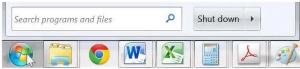
Step 4A

Step 4B
![C:\Windows\system32\cmd.exe Microsoft Windows [Version 6.1.7601] Copyright (c) 2009 Microsoft Corporation. All rights reserved. C:\>ipconfig](/content/2026/05/1055656/images/bb414e4f56b7c55a974f7a08d6e747eda790b65c2a1c4e4e8c2347e54c86128d.jpg)
Step 4C
Figure 7: Determining Computer IP Address

Figure 8: Computer IP Address).
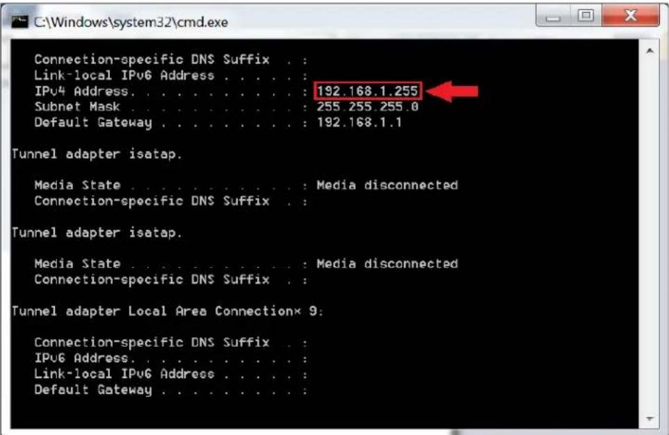
Figure 8: Computer IP Address
- If the IPv4 Address (shown in the red box of Figure 8) does NOT begin with the numbers 192.168.168.x, then perform the following steps (refer to Figure 9 through Figure 12):
A. Type exit and press Enter on the keyboard.
B. Move the mouse to the bottom of the screen and click on the Start button at the lower left.
C. Click on Control Panel
D. Click on Network and Internet
E. Click on Network and Sharing Center
F. Click on Local Area Connection
G. Click on Properties
H. Click on Internet Protocol Version 4 (TCP/IPv4). It will turn blue.
I. Click on Properties
J. Click the Use the following IP address radio button.
K. In the IP address field, type the following:
192.168.168.x
Where x can be any number from 2 to 254 except for 50 (since 50 is the MNC address). The example in Figure 12 has the PC set to a Static IP address of 192.168.168.12
L. In the Subnet mask field, type the following:
255.255.255.0
M. Click on OK.

Step 5A

Steps 5B-5C
Figure 9

Step 5D
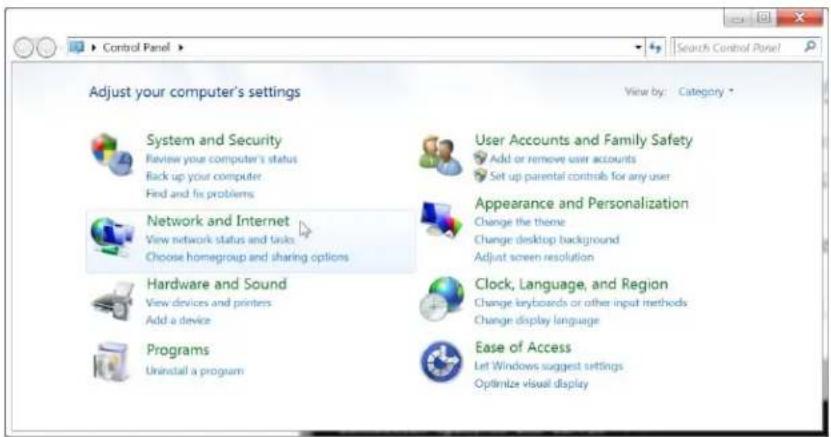
Step 5E

Step 5F
Figure 10

Step 5G

Steps 5H-5I
Figure 11

Steps 5J-5K-5L-5M
Figure 12
The computer is now ready to communicate with the MNC.
Refer to Figure 13: Internet Browser Entry.
- Open up an Internet browser (Explorer, Chrome, Firefox, etc.) and type the following address in the address bar near the top of the screen:
hp://192.168.168.50/mnc/
NOTE: mnc must be written in lower case

Figure 13: Internet Browser Entry
Refer to Figure 14 Login Screen
- The MuxLab Pro Digital Network Controller Web interface Login Screen will appear.

Figure 14 Login Screen
- In the User Name field, type admin. Use lower case.
- In the Password field, type admin. Use lower case.
- Click Log in.

Refer to
© 2015 Mudlab Inc. version: 1.0.2
Figure 15 Network Settings Screen
-
Click the Settings tab. The Network Settings screen will appear.
-
Next to Use DHCP, ensure that the No radio button is selected.
-
In the IP address field, type the first 3 entries of the IP address of the network subnet on which the MNC will be installed, which in our example is 192.168.2.x.
For example, type the following in the MNC IP address field:
192.168.2.x
Where x in our example can be any number from 3 to 254, and since “1” was used above for the Ethernet Switch and “2” was used for the Router, then for this example we will
select "5" for a Static IP address of 192.168.2.5, see

Figure 15. Just make sure the Static IP address for the MNC does conflict with the Static IP address of the Ethernet Switch and the Router or any other Static IP address already pre-assigned in the given network.
- In the Network mask field, type 255.255.255.0
- In the Router field, type the IP address of the network Router (which in our example is 192.168.2.2).

Figure 15 Network Settings Screen
Click on Save. The MNC will reboot (see
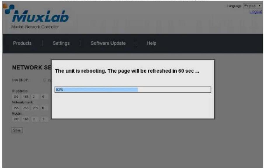
- Figure 16 MNC Reboot Screen).

Figure 16 MNC Reboot Screen
The MNC is now configured to work with your network router.
Process 2: Physically installing the MNC to the network
- Disconnect the Ethernet cable from the computer and connect it to either the Router or the Ethernet Switch. Ensure that the other end is still connected to the MNC. Also make sure that the Router is connected to the Ethernet Switch.
3.4. Ethernet Web Interface – Device Management
The Ethernet Web interface allows the user to manage the MNC and the AV over IP product family of extenders remotely from a Windows based computer. Make sure the computer is set to a Static IP address in the same subnet, which in our example is 192.168.2.x. Follow steps 4, 5 & 6 in section 3.3 on how to accomplish this, but set using the subnet 192.168.2.x
Ensure that the computer is connected by an Ethernet cable to the network router on which the MNC is physically installed. Open up an Internet browser (Explorer, Chrome, Firefox, etc.) and type in the MNC IP address in the address bar near the top of the screen, such as, which in our example is 192.168.2.5:
192.168.2.5/mnc/
NOTE: 192.168.2.x represents the first three IP address entries of the network subnet on which the MNC is physically installed.
The MuxLab Network Controller Web interface Login Screen will appear (Figure 17).
Figure 17 Login Screen

In the User Name field, type admin. Use lower case.
In the Password field, type admin. Use lower case.
Click Log in.
You are now ready to manage the MuxLab Pro Digital Network Controller.
Products Screen
Once the user has logged in, the Products screen will appear (Figure 18).

Figure 18: Products Screen
In the following section we will be using the MuxLab 500752 HDMI over IP Extender as an example of how to use the MuxLab Pro Digital Controller to manage MuxLab AV over IP devices.
In the SELECT A PRODUCT drop down box, click on HDMI over IP (500752) as shown in Figure 18.
A dialog box will appear, asking the user if he wants to load a previously saved device list (in case such a list has already been stored). This dialog box will appear even if no device list was previously saved.
Two tabs appear in the Products screen (Set-up and Matrix), with the Set-up tab being active by default.
The Set-up tab offers the user two options for the type of set-up allowed: Automatic or Manual.
Automatic means that the software will scan the system for every dip-switch enabled device and override its manual dip-switch address settings and place these units under software address control.
Manual means that the software will allow the manual dip-switch address settings of any found device to remain active.
After selecting Automatic or Manual, click on Launch discovery. The system will then scan the network for all source side devices (in this example 500752 Transmitters) and display side devices (in this example 500752 Receivers), and will display the scan results in tabular form (see Figure 19).
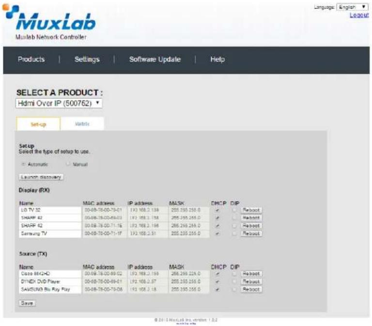
Figure 19: Sources and Displays
Each 500752 Transmitter and Receiver can be assigned an arbitrary descriptive name, normally reflecting the end device that it is terminated to. To change the name of any Display (RX) or Source (TX) device, click the Name field to edit its contents. Several Name fields can be edited before saving changes (as shown in
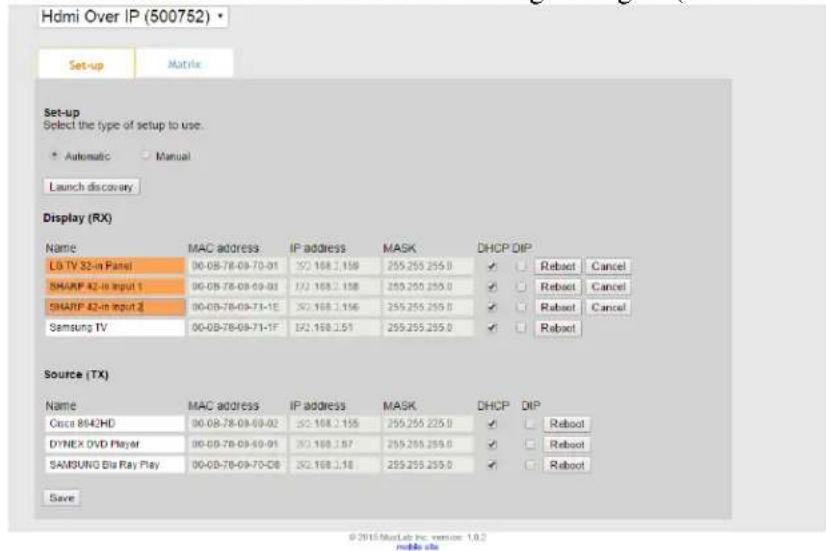
Figure 20).
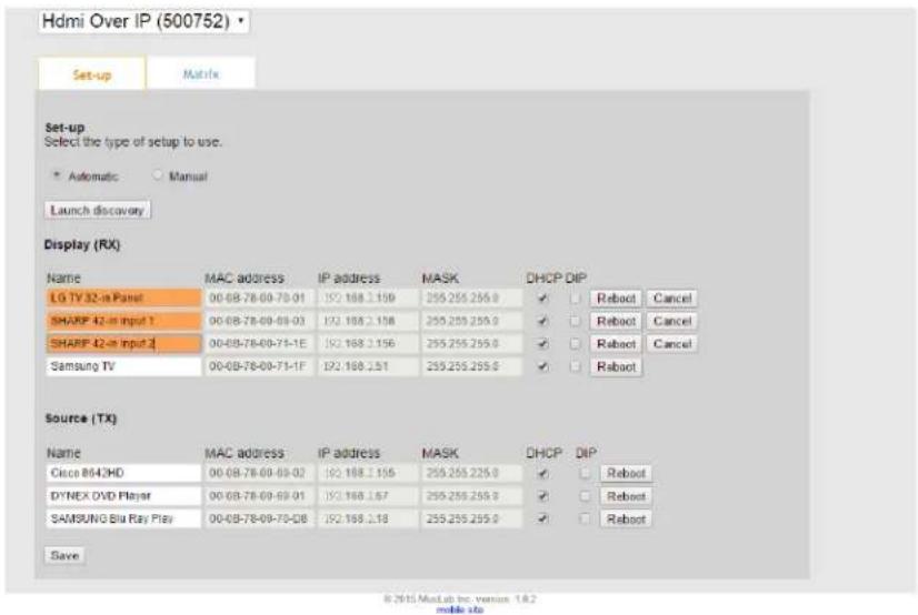
Figure 20: Name Changes
To save all name changes, click on Save. A green UPDATED tag will appear next to newly changed names (see Figure 21).

Figure 21: Saving Name Changes
The Matrix tab of the Products screen allows the user to connect any Display to any Source. The user also has the option of using Presets to save connection schemes (“presets”), as well as to edit and delete existing presets (see Figure 22).
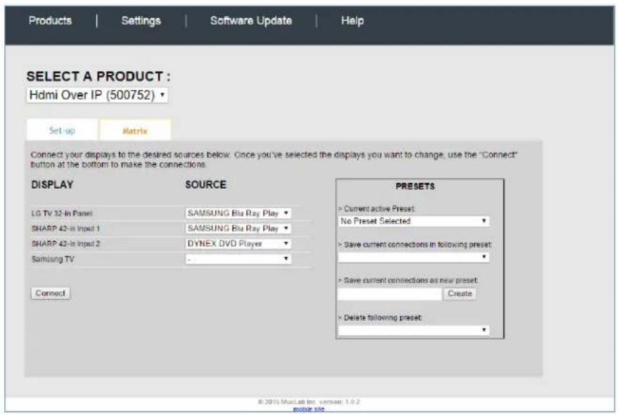
Figure 22: Matrix Tab
Figure 23 and Figure 24 demonstrate how to connect a display to a source. The user clicks on the drop-down list next to the given display (for example “Samsung TV”) and selects which source to connect to (Figure 23).

Figure 23: Change Connection
Once the selection is made (the user can change any or all connections between displays and sources), click on Connect to finalize the change. A green SUCCESS tag will appear next to the new or changed connection (Figure 24).

Figure 24: Finalize Change
To create a new preset, the user clicks the > Save current connections as new preset field (see Figure 25) and types a name. This assigned preset name will be linked to the existing connection scheme being shown within the Matrix tab.
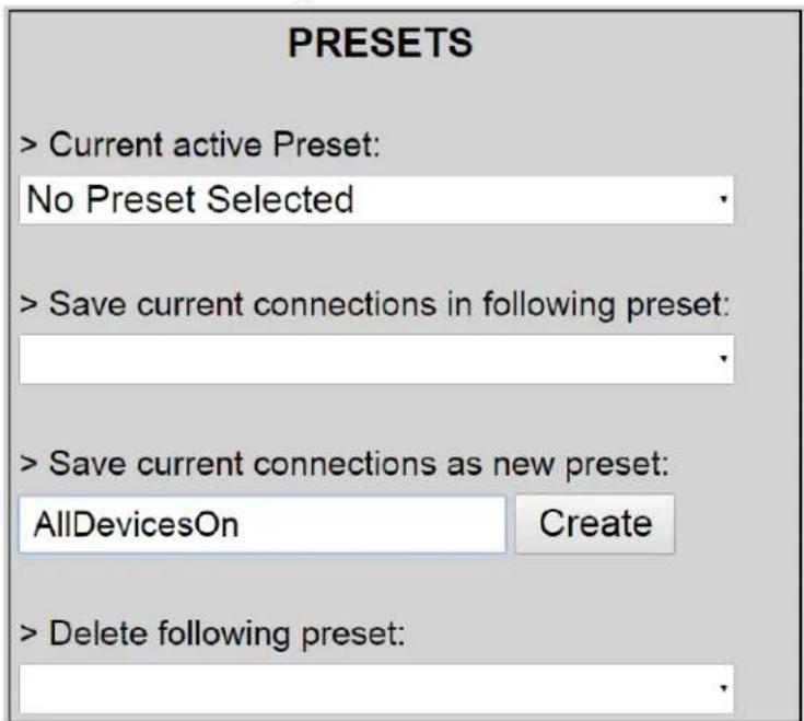
Figure 25: Create New Preset
To save this preset, the user clicks on Create. A green SUCCESS tag will appear next to the > Save current connections as new preset field (see Figure 26).

Figure 26: Confirmation of New Preset
To delete a preset, the user clicks the > Delete following preset drop-down box and selects a preset name from the list shown (as in Figure 27).

Figure 27: Delete Preset
Once selected, the preset will be deleted and a green SUCCESS tag will appear next to the > Delete following preset field (see Figure 28).

Figure 28: Confirmation of Deleted Preset
To re-save the current connections as displayed in the Matrix tab under an existing Preset name, the user clicks the > Save current connection in following preset dropdown box and selects a preset name (Figure 29).
Figure 29: Change Current Active Preset
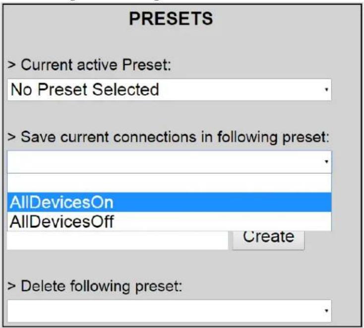
Once selected, the Preset will be saved and a green SUCCESS tag will appear next to the > Save current connections in following preset field (see Figure 30).

Figure 30: Confirmation of Changed Preset Name
In order to activate an existing Preset, select > Current active Preset, and select the Preset name from the drop-down box and the Preset will become active. In addition the active Preset will be displayed in the Current active Preset field.
Settings Screen
The Settings screen contains two tabs: Network and Administration.
The Network tab (see Figure 31) is used to change the IP address of the MuxLab Network Controller (MNC), the network mask, as well as the router IP address. It also allows the user to enable or disable DHCP.

Figure 31: Settings Screen: Network Tab
The Administration tab (see Figure 32) is used to change administrator passwords. The user must enter their:
- Existing Password
- Their new password
- And their new password a second time (to confirm that there are no entry errors)
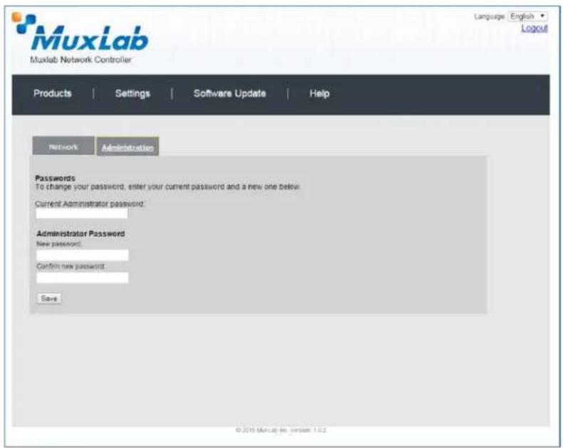
Figure 32: Settings Screen: Administration Tab
3.5. Mobile Interface
The mobile interface is presented below in a series of annotated snapshots. Note that at any time, the user can navigate to the regular website by clicking regular site at the bottom of the screen. The mobile device must be connected to the same WiFi network as configured on the router.

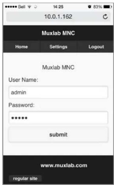
The home page of the MuxLab MNC mobile interface presents the user with two entry fields: User Name and Password.
By default, both the User Name and Password are admin (case-sensitive for Password).
The user is prompted to select a product from a drop-down list.
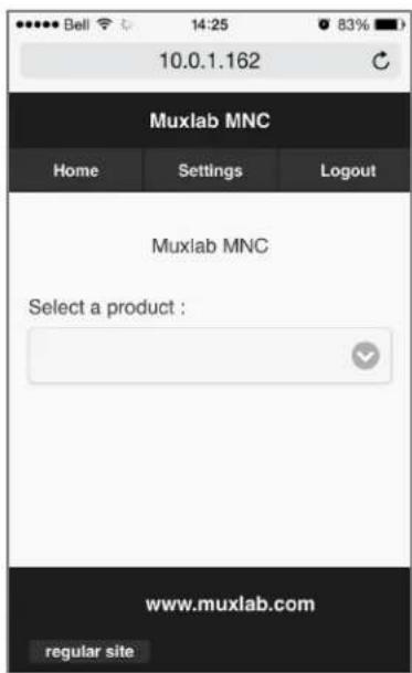
As per our earlier product example, the user can then select the:
Hdmi Over IP (500752).

The selected product (HDMI OVER IP) appears at the top of the sub-menu. The user has three options from the sub-menu, Launch Discovery, Matrix and Get Devices.
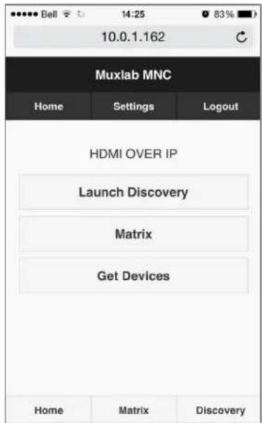
After selecting Launch Discovery in the sub-menu, the user is presented with a list of Sources (TX) and Displays (RX).
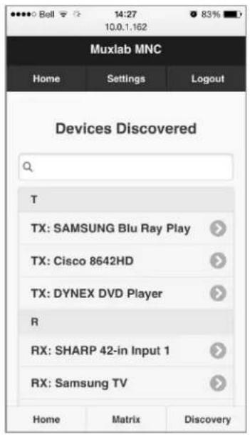
After selecting any Source or Display from the list, the user is presented with the MAC and IP Address of the device in question.

4. Troubleshooting
Table 6 lists common problems, as well as their possible causes and solutions. If the information below does not solve the problem, technical support contact information can be found at the end of this section.
| PROBLEM | POSSIBLE SOLUTIONS |
| Unable to connect computer to MNC | Ensure the computer IP subnet address matches the IP subnet address of the MNC |
| Ensure that http://192.168.168.50/mnc/ is written in lower case | |
| Unable to connect computer to Ethernet Switch or to the Router | Ensure the computer IP subnet address matches the IP subnet address of the Ethernet Switch and Router. |
| General communication problem between devices | As a general rule, all devices required to communicate together on the same local network, must have an IP address in the same subnetStatic IP address must be unique and in the same subnet.DHCP addresses must be assigned within the same subnet and configured at the DHCP server not to overlay with any assigned Static IP addresses. |
Table 6: Troubleshooting
When contacting your nearest MuxLab dealer or MuxLab Technical Support at 877-689-5228 (toll free in North America) or (+1) 514-905-0588 (International), please have the following information ready:
- Unit model number.
• Description of problem. - List of tests performed.
5.
Appendix
A. IP Commands
Please note that commands are case sensitive and arguments must be separated by a single space. Commands must be entered as shown and ended with a carriage return.
The IP command API use HTTP POST with JSON data. Each IP command must be sent to the following URL: http://aaa.bbb.ccc.ddd/mnc/secure_api.php
Each IP command must contain the MuxLab Network Controller (MNC) username and password:
aaa.bbb.ccc.ddd the MNC IP address
p_username the MNC username
p_password the MNC user password
FORMAT
The IP command (JSON data) has the following formats:
Command without data parameters:
{"p_targetId": <target id>, "p_cmd": "<command name>", "p_username": "<MNC User Name>", "p_password": "<MNC password>"}
Response format without additional data:
{"p_targetId": <target id>, "p_cmd": "<command name>", "p_rspStatus": "<command status>", "p_msg": "<a message>"}
Command with data parameters:
{"p_targetId": <target id>, "p_cmd": "<command name>", "p_username": "<MNC User Name>", "p_password": "<MNC password>", "p_data": [{"key1": value1, "key2": value2, ... }]}
Response format with additional data:
{"p_targetId": <target id>, "p_cmd": "<command name>", "p_rspStatus": "<command status>", "p_msg": "<a message>", "p_data": [{"key1": value1, "key2": value2, ...}]}
The “p_data” field will depend on the associated command.
The "p_targetId" value is:
“0” to send a command for the MNC
“1” to send a command for the “500752” product
COMMAND/RESPONSE LIST
1. Automatic Discovery
Description:
The system will retrieve all the devices in the network and automatically send all the necessary updates to the devices in order to configure them properly (duplicate IP addresses will not be solved by the system; the user must resolve this kind of issue). The system will then return a list of devices found with their attributes.
Command:
{"p_targetId":1,"p_cmd":"launch_discovery_auto","p_userName:<MNC User Name >","p_password":"<MNC password>"}
Response:
{"p_targetId":1,"p_cmd":"launch_discovery_auto","p_rspStatus:"SUCCESS","p_msg":"<a message>",
"p_data":[{"productName":"<value>", "modelName":"<value>", "customName":"<value>", "mac":"<value>", "ip":"<value>", "mask":"<value>", "isDhcp":<0/1>," multicastGroupIp":"<value>", "videoResolution":"<value>", "videoFrameRate":"<value>", "audioFormat":"<value>", "isVideoSignalDetected":<0/1>, "isIrOn":<0/1>, "isDipSwitchEnabled":<0/1>, "isDisplayConnected":<0/1>, "isScreenImageOn":<0/1>, "isScreenTextOn":<0/1>, "connectedMac":"<value>}", { ... }, ...]
NOTE: Red text signifies additional attributes for RX devices.
2. Manual Discovery
Description:
The system will retrieve all the devices in the network and will return a list of devices found with their attributes. No other actions will be performed.
Command:
{"p_targetId":1,"p_cmd":"launch_discovery","p_username:"<MNC User Name >","p_password":"<MNC password>"}
Response:
{"p_targetId":1,"p_cmd":"launch_discovery","p_rspStatus:"SUCCESS","p_msg":"<a message>",
"p_data":[{"productName":"<value>", "modelName":"<value>", "customName":"<value>", "mac":"<value>", "ip":"<value>", "mask":"<value>", "isDhcp":<0/1>, "multicastGroupIp":"<value>", "videoResolution":"<value>", "videoFrameRate":"<value>", "audioFormat":"<value>", "isVideoSignalDetected":<0/1>, "isIrOn":<0/1>, "isDipSwitchEnabled":<0/1>, "isDisplayConnected":<0/1>, "isScreenImageOn":<0/1>, "isScreenTextOn":<0/1>, "connectedMac":"<value>"}, { ... }, ...]
NOTE: Red text signifies additional attributes for RX devices.
3. Get Devices from the Database
Description:
The system will retrieve all the devices currently stored in the database
Command:
{"p_targetId":1,"p_cmd":"get_devices","p_username:"<MNC User Name >","p_password":"<MNC password>"}
Response:
{"p_targetId":1,"p_cmd":"get_devices","p_rspStatus":"SUCCESS","p_msg":"<a
message>", "p_data": [{"productName":"<value>", "modelName":"<value>", "customName":"<value>", "mac":"<value>", "ip":"<value>", "mask":"<value>", "isDhcp":"<0/1>, "multicastGroupIp":"<value>", "videoResolution":"<value>", "videoFrameRate":"<value>", "audioFormat":"<value>", "isVideoSignalDetected":"<0/1>, "isIrOn":"<0/1>, "isDipSwitchEnabled":"<0/1>, "isDisplayConnected":"<0/1>, "isScreenImageOn":"<0/1>, "isScreenTextOn":"<0/1>, "connectedMac":"<value>"}, { ... }, ...]
NOTE: Red text signifies additional attributes for RX devices.
4. Update Some Device Attributes
Description:
The system will update the devices specified with the new attributes provided. Note that the devices to be updated MUST already exist in the MNC database.
Command:
{"p_targetId":1,"p_cmd":"update_devices","p_username:"<MNC User Name >","p_password":"<MNC password >","p_data":[<mac":"<device mac address>>,<attribute name>:<attribute value>,..."},{<mac":"<device mac address>>,<attribute name>:<attribute value>,...}],...]}
List of attribute names that can be modified:
"customName" Set the custom name to give to this device
"ip" Set the device IP address (Eg. "192.168.1.80")
"mask" Set the device mask (Eg. "255.255.255.0")
"isDhcp" Set the DHCP on (1) or off (0) (Eq. 1)
"isDipSwitchEnabled" Set the dip switch on(1) or off(0) (Eg.: 0)
Response:
{"p_targetId":1,"p_cmd":"update_devices","p_rspStatus:"SUCCESS","p_msg":"<a
message>", "p_data": [{"productName":"<value>", "modelName":"<value>", "customName":"<value>", "mac":"<value>", "ip":"<value>", "mask":"<value>", "isDhcp":"<0/1>, "multicastGroupIp":"<value>", "videoResolution":"<value>", "videoFrameRate":"<value>", "audioFormat":"<value>", "isVideoSignalDetected":"<0/1>, "isIrOn":"<0/1>, "isDipSwitchEnabled":"<0/1>, "isDisplayConnected":"<0/1>, "isScreenImageOn":"<0/1>, "isScreenTextOn":"<0/1>, "connectedMac":"<value>"}, { ... }, ...]
NOTE: Red text signifies additional attributes for RX devices.
5. Reboot Device
Description:
The system will reboot the devices
Command:
{"p_targetId": 1, "p_cmd": "reboot_devices", "p_username": "<MNC User Name >", "p_password": "<MNC password >", "p_data": [{"mac":"<device mac address>"}, {...}, ...]}
Response:
{"p_targetId":1,"p_cmd":"update_devices","p_rspStatus:"SUCCESS","p_msg":"<a message>", "p_data":[{"mac":"<device mac address>", "rspStatus":"SUCCESS or FAILED","msg":""}, ...]}
6. Connect/Disconnect Device
Description:
Perform a connect/disconnect between devices
Command:
{"p_targetId": 1, "p_cmd": "connection", "p_username": "<MNC User Name >", "p_password": "<MNC password >", "p_data": [{"macRx":"<Rx device mac address>","macTx":"<Tx device mac address>"}, {...}, ...]} "macRx": the RX mac address to connect/disconnect "macTx": - To disconnect, use "00-00-00-00-00-00" - To connect, use the TX device MAC address
Response:
{"p_targetId":1,"p_cmd":"connection","p_rspStatus:"SUCCESS","p_msg":"<a message>", "p_data":[{"macRx":"<Rx device mac address>", "macTx":"<Tx device mac address>", "rspStatus":"SUCCESS or FAILED","msg":""}]
7. Select and Apply a Preset
Description:
Apply a (an existing) preset
Command:
{"p_targetId":1,"p_cmd":"select_preset","p_username:"<MNC User Name >","p_password":"<MNC password >","p_data":[{"presetId":"<preset id number>"}]
Response:
{"p_targetId":1,"p_cmd":"select_preset","p_rspStatus:"SUCCESS","p_msg":"<a message>", "p_data":[{"macRx":"<Rx device mac address>", "macTx":"<Tx device mac address>", "rspStatus":"SUCCESS or FAILED", "msg":""}, ...]
NOTE: "p_data" will return all connection results that took place.
8. Save Current Matrix Connections in a Specific Preset
Description:
Save the current matrix connections in a specific (existent) preset
Command:
{"p_targetId": 1, "p_cmd": "save_preset", "p_username": "<MNC User Name >", "p_password": "<MNC password >", "p_data": [{"presetId":"<preset id number>"}]}
Response:
{"p_targetId":1,"p_cmd":"save_preset","p_rspStatus:"SUCCSESS","p_msg":"<a message>", "p_data":[{"presetId":"<preset ID number>"}]
9. Save Current Matrix Connections in a NEW Preset Name
Description:
Save the current matrix connections in a NEW preset name
Command:
{"p_targetId":1,"p_cmd":"create_preset","p_username:"<MNC User Name >","p_password":"<MNC password >","p_data":[{"presetName":"<a new preset name>"}]}
Response:
{"p_targetId":1,"p_cmd":"create_preset","p_rspStatus:"SUCCSESS","p_msg":"<a message>", "p_data":[{"prestName":"<name of the preset>", presetId":"<preset ID number>"}]
10. Delete a Preset
Description:
Delete a preset
Command:
{"p_targetId":1,"p_cmd":"delete_preset","p_username:"<MNC User Name >","p_password":"<MNC password >","p_data":[{"presetId":"<preset id number>"}]
Response:
{"p_targetId":1,"p_cmd":"delete_preset","p_rspStatus:"SUCCSESS","p_msg":"<a message>", "p_data":[{"presetId":"<preset ID number>"}]
11. Modify Network Setting of the MNC
Description:
Modify any network settings of the MNC (ip/mask/gateway/dhcp)
Command:
{"p_targetId": 0, "p_cmd": "modifyNetSettings", "p_username": "<MNC User Name >", "p_password": "<MNC password >", "p_data": [{"dhcp":"<0/1>"}, {"ip":"<ip address>"}, {"mask":"<mask address>"}, {"gateway":"<gateway address>"}]}
Response:
{"p_targetId":0,"p_cmd":"modifyNetSettings","p_rspStatus:"SUCCESS/FAILED","p_msg":"<a message>"}
12. Modify Administrator password of the MNC
Description:
Modify the administrator password of the MNC
Command:
{"p_targetId": 0, "p_cmd": "changeAdminPswd", "p_username": "<MNC User Name >", "p_password": "<MNC password >", "p_data": [{"username":"<the user name>"}, {"currpswd":"<current password>"}, {"newpswd":"<new password>"}]}
Response:
{"p_targetId":0,"p_cmd":"modifyNetSettings","p_rspStatus:"SUCCESS/FAILED","p_msg":"<a message>"}
6. Product Warranty Policy
Items Under Warranty - Company Policy
MuxLab guarantees its products to be free of defects in manufacturing and workmanship for the warranty period from the date of purchase. If this product fails to give satisfactory performance during this warranty period, MuxLab will either repair or replace this product at no additional charge, except as set forth below. Repair and replacement parts will be furnished on an exchange basis and will be either reconditioned or new. All replaced parts and products become the property of MuxLab. This limited warranty does not include repair services for damage to the product resulting from accident, disaster, misuse, abuse, or unauthorized modifications or normal decay of battery driven devices. Batteries, if included with the product, are not covered under this warranty.
Limited warranty service can be obtained by delivering the product during the warranty period to the authorized MuxLab dealer from whom you purchased the product, or by sending it to MuxLab. MuxLab will not accept any such product for repair without a Return Material Authorization number (RMA#) issued by its Customer Service Department and a proof of purchase date. If this product is delivered to MuxLab by mail, you agree to assume risk of loss or damage in transit, to prepay shipping charges to the warranty service location, and to use the original shipping container or equivalent.
THE ABOVE LIMITED WARRANTY IS THE ONLY WARRANTY COVERING YOUR MUXLAB PRODUCT. THERE ARE NO OTHER WARRANTIES, EXPRESSED OR IMPLIED, INCLUDING WARRANTIES OF MERCHANTABILITY OR FITNESS FOR A PARTICULAR PURPOSE. SOME STATES DO NOT ALLOW LIMITATIONS ON IMPLIED WARRANTIES, SO THE ABOVE LIMITATION MAY NOT APPLY TO YOU.
IF THIS PRODUCT IS NOT IN GOOD WORKING ORDER, YOUR SOLE REMEDY SHALL BE REPAIR OR REPLACEMENT AS PROVIDED FOR ABOVE. IN NO EVENT SHALL MuxLab BE LIABLE TO YOU FOR ANY DAMAGES, INCLUDING ANY LOSS OF PROFITS, LOST SAVINGS, OR OTHER INCIDENTAL OR CONSEQUENTIAL DAMAGES ARISING OUT OF THE USE OF OR INABILITY TO USE THIS PRODUCT, EVEN IF MUXLAB OR AN AUTHORIZED MuxLab DEALER HAS BEEN ADVISED OF THE POSSIBILITY OF SUCH DAMAGES; NOR WILL MUXLAB BE LIABLE FOR ANY CLAIM BY ANY OTHER PARTY. SOME STATES DO NOT ALLOW THE EXCLUSION OR LIMITATION OF INCIDENTAL OR CONSEQUENTIAL DAMAGES FOR CONSUMER PRODUCTS, SO THE ABOVE LIMITATIONS OR EXCLUSIONS MAY NOT APPLY TO YOU. THIS WARRANTY GIVES YOU SPECIFIC LEGAL RIGHTS. YOU MAY ALSO HAVE OTHER RIGHTS WHICH MAY VARY FROM STATE TO STATE.
Warranty Periods
Any product found to be defective within three (3) months of invoice, including one (1) month shelf life, may be returned for replacement by a new unit or a satisfactory repair within one (1) month of receiving any returned product. The customer must provide MuxLab with the serial number and proof of purchase of the defective unit being returned. All R.M.A.'s issued are subject to inspection by MuxLab, and will be returned to customer if not properly package – units must be returned in original container or equivalent. MuxLab will not accept any such product for repair without an authorization for its Technical Support department and without a return authorization number issued by MuxLab Customer Service department. For credit & replace R.M.A., customer will be liable to pay replacement invoice if defective products are not returned. Product more than six months old, including shelf life.
The defective unit must be returned prepaid to MuxLab and then the unit will be repaired or if repair is not possible, replaced by an equivalent unit and returned to the customer within one (1) month of receiving any returned product. There is no charge for repair (parts and labor) during the full warranty period.
Items Defective and not under Warranty
For products which are no longer under warranty the policy is repair and return. An amount of 25% of the products published list price at the time of purchase will be charged. Customer must issue a purchase order to cover the cost of repair. Each unit will be returned to the customer within one (1) month from receipt of the unit by MuxLab. The defective unit must be returned prepaid to MuxLab. The repaired unit will be returned to the customer FOB MuxLab. The repaired unit has a 90 day warranty.

MuxLab Inc.
8495 Dalton Road
Mount Royal, Quebec
Canada H4T 1V5
Tel.: +1 (514) 905-0588 Fax: +1 (514) 905-0589
Toll Free (North America): 877 689-5228
URL: www.muxlab.com
E-mail: videoease@muxlab.com
- MuxLab Pro Digital Network Controller (MNC)
- (Model: 500811)
- Copyright Notice:
- Trademarks:
- Table of Contents
- Overview....4
- Technical Specifications ....6
- Installation and Use ....7
- Troubleshooting....38
- Appendix....39
- Product Warranty Policy ....46
- Description
- Features
- Front Panel
- Back Panel
- Side Panel
- Technical Specifications
- Installation and Use
- Part List
- Product Overview
- Installation Procedure
- Setting the Ethernet Switch & Router to the same Subnet as MuxLab Devices:
- Setting MuxLab Devices, Ethernet Switch and Router to an Existing Subnet:
- Note:
- Process 1: Configuring the IP address of the MNC
- Refer to Figure 14 Login Screen
- Figure 15 Network Settings Screen
- 192.168.2.x
- Process 2: Physically installing the MNC to the network
- Ethernet Web Interface – Device Management
- Products Screen
- Settings Screen
- Mobile Interface
- Troubleshooting
- IP Commands
- FORMAT
- COMMAND/RESPONSE LIST
- Automatic Discovery
- Description:
- Command:
- Response:
- Manual Discovery
- Get Devices from the Database
- Update Some Device Attributes
- List of attribute names that can be modified:
- Reboot Device
- Connect/Disconnect Device
- Select and Apply a Preset
- Save Current Matrix Connections in a Specific Preset
- Save Current Matrix Connections in a NEW Preset Name
- Delete a Preset
- Modify Network Setting of the MNC
- Modify Administrator password of the MNC
- Product Warranty Policy
- Items Under Warranty - Company Policy
- Warranty Periods
- Items Defective and not under Warranty
Brand : MuxLab
Model : 500760-KVM
Category : Controller