Unity XT 680F - NAS DELL - Free user manual and instructions
Find the device manual for free Unity XT 680F DELL in PDF.

| Product Type | All-Flash Storage Array (NAS/SAN Unified) |
| Model | Dell Unity XT 680F |
| Form Factor | 2U Rackmount |
| Dimensions (H x W x D) | 8.68 cm x 48.3 cm x 73.3 cm (3.4" x 19" x 28.9") |
| Weight (fully loaded) | Approximately 24 kg (53 lbs) |
| Power Supply | Dual redundant, hot-swappable 1200W AC PSU |
| Maximum Raw Capacity | Up to 368 TB (with 24 x 15.36 TB SSDs) |
| Drive Support | 24 x 2.5" SAS SSDs (hot-swappable) |
| Controllers | Dual active-active storage processors |
| Memory (per controller) | 128 GB DDR4 |
| Supported Protocols | FC, iSCSI, NFS, SMB, S3 |
| Data Reduction (Inline) | Compression and deduplication (always on) |
| RAID Levels | RAID 5, 6, 10; dynamic RAID (pool-based) |
| Management | Unisphere web-based GUI, CLI, REST API |
| Cooling | Dual fan modules, redundant hot-swappable |
| Operating Temperature | 10°C to 35°C (50°F to 95°F) |
| Certifications | FCC, CE, UL, RoHS |
| Warranty | 3-year hardware warranty with (optional) extended support |
| Spare Parts Availability | Field-replaceable units: PSU, fan, controller, drive, m.2 boot module |
Frequently Asked Questions - Unity XT 680F DELL
User questions about Unity XT 680F DELL
0 question about this device. Answer the ones you know or ask your own.
Ask a new question about this device
Download the instructions for your NAS in PDF format for free! Find your manual Unity XT 680F - DELL and take your electronic device back in hand. On this page are published all the documents necessary for the use of your device. Unity XT 680F by DELL.
USER MANUAL Unity XT 680F DELL
Dell EMC Unity™ All Flash and Unity Hybrid Dell EMC Unity 480/F, Unity 680/F, Unity 880/F
Installation and Service Guide
302-005-519
REV 01
Copyright © 2019 Dell Inc. or its subsidiaries. All rights reserved.
Published June 2019
Dell believes the information in this publication is accurate as of its publication date. The information is subject to change without notice.
THE INFORMATION IN THIS PUBLICATION IS PROVIDED "AS-IS." DELL MAKES NO REPRESENTATIONS OR WARRANTIES OF ANY KIND WITH RESPECT TO THE INFORMATION IN THIS PUBLICATION, AND SPECIFICALLY DISCLAIMS IMPLIED WARRANTIES OF MERCHANTABILITY OR FITNESS FOR A PARTICULAR PURPOSE. USE, COPYING, AND DISTRIBUTION OF ANY DELL SOFTWARE DESCRIBED IN THIS PUBLICATION REQUIRES AN APPLICABLE SOFTWARE LICENSE.
Dell, EMC, and other trademarks are trademarks of Dell Inc. or its subsidiaries. Other trademarks may be the property of their respective owners. Published in the USA.
Dell EMC
Hopkinton, Massachusetts 01748-9103
1-508-435-1000 In North America 1-866-464-7381
www.DellEMC.com
CONTENTS
Additional resources 7
Chapter 1 Installation Procedures 9
Hardware terms....10
Release information.... 10
Before you begin....10
Installation workflow including optional DAEs.... 10
Site and equipment preparation.... 11
Unpack the DPE....12
Record the product serial number from the DPE....13
Install the rails in the cabinet....13
Install the DPE on the rails.... 15
Secure the system in the cabinet.... 16
Attach the storage processors to the network....16
Install optional DAEs....17
Connect power to the DPE....17
Power up optional DAEs.... 18
Verify status LEDs.... 18
Installing the front bezel....20
Connect a Windows-based computer to your storage system....21
Automatically assigning a dynamic storage system management port IP address....22
Manually assigning a static storage system management port IP address....23
Download and install the Connection Utility software.... 23
Run the Connection Utility....24
Unpack the (optional) disk-array enclosures.... 25
15-drive DAE container contents.... 25
25-drive DAE container contents....27
Install the disk array enclosure....28
Install 15-drive DAE....28
Install 25-drive DAE....31
Cabling the DPE to a DAE....35
Cabling the first optional DAE to create back-end bus 1.... 36
Cabling the second optional DAE to create back-end bus 0....37
Cabling an expansion DAE to an existing DAE to extend a back-end bus.... 37
Connecting power to the DAE.... 38
Chapter 2 Service Procedures 41
Replace a faulted disk in the DPE.... 42
Identifying and locating the faulted part in Unisphere....42
Remove a faulted 2.5" disk....42
Install a 2.5" disk....42
Verifying the operation of the new part in Unisphere....43
Returning a faulted part....43
Add a new disk in the DPE.... 44
Removing the front bezel.... 44
Remove a disk filler module.... 44
Install a 2.5" disk....45
Verifying the operation of the new part in Unisphere....45
Replace a power supply.... 46
Identifying and locating the faulted part in Unisphere....46
DPE power supply LEDs.... 46
Remove a power supply....46
Install a power supply....47
Verifying the operation of the new part in Unisphere....48
Returning a faulted part....48
Replace an embedded module.... 49
Identifying and locating the faulted part in Unisphere....49
Preparing the SP assembly for service.... 49
Embedded module LEDs.... 50
Remove a faulted embedded module....51
Transfer the 4-port card....53
Install an embedded module....55
Rebooting a SP assembly into Normal Mode.... 55
Verifying the operation of the new part in Unisphere....56
Add a 4-port card.... 56
Preparing the SP assembly for service.... 56
Remove an embedded module.... 57
Identify the location for the new 4-port card....58
Install a 4-port card.... 58
Install an embedded module....59
Adding the 4-port card to SP B.... 60
Rebooting a SP assembly into Normal Mode.... 60
Committing the new I/O ports.... 61
Verifying the operation of the new part in Unisphere.... 61
Replace a 4-port card....61
Identifying and locating the faulted part in Unisphere.... 61
Preparing the SP assembly for service.... 62
Embedded module LEDs.... 62
Remove an embedded module.... 64
Remove a 4-port card....65
Install a 4-port card.... 66
Install an embedded module....67
Rebooting a SP assembly into Normal Mode.... 68
Verifying the operation of the new part in Unisphere....68
Add an SFP....69
Install an SFP module.... 69
Committing the new I/O ports....69
Verifying the operation of the new part in Unisphere....70
Replace a faulted SFP....70
Identifying and locating the faulted part in Unisphere....70
Remove an SFP module.... 70
Install an SFP module....71
Verifying the operation of the new part in Unisphere.... 71
Returning a faulted part....72
Replace an I/O module....72
Identifying and locating the faulted part in Unisphere.... 72
Preparing the SP assembly for service.... 72
DPE I/O module LEDs....73
Remove a faulted I/O module.... 73
Install a new I/O module....74
Rebooting a SP assembly into Normal Mode.... 75
Verifying the operation of the new part in Unisphere....75
Returning a faulted part....75
Add an I/O module....76
Locating a slot for a new I/O module.... 76
Remove a filler I/O module.... 76
Install a new I/O module....76
Verifying that the new I/O ports are recognized.... 77
Adding the I/O module to SP B....78
Committing the new I/O ports....78
Identifying and locating the faulted part in Unisphere....78
Preparing the storage processor (SP) for service....79
Remove the SP assembly.... 80
Remove the top cover from the SP assembly.... 82
Remove the faulted fan module.... 83
Install a new fan module....84
Install the top cover on the SP assembly.... 84
Install the SP assembly....85
Rebooting an SP assembly into Normal Mode.... 86
Verifying the operation of the new part in Unisphere....87
Returning a faulted part....87
Replace a dual inline memory module (DIMM)....88
Identifying and locating the faulted part in Unisphere....88
Preparing the storage processor (SP) for service.... 88
Remove the SP assembly.... 89
Remove the top cover from the SP assembly....91
Remove the faulted dual inline memory module.... 92
Install the dual inline memory module.... 92
Install the top cover on the SP assembly.... 93
Install the SP assembly....94
Rebooting an SP assembly into Normal Mode.... 95
Verifying the operation of the new part in Unisphere....96
Returning a faulted part....96
Replace an M.2 SSD....96
Identifying and locating the faulted part in Unisphere....96
Preparing the storage processor (SP) for service....97
Remove the SP assembly.... 98
Remove the top cover from the SP assembly.... 100
Remove the faulted M.2 SSD....101
Install the M.2 SSD.... 102
Install the top cover on the SP assembly....103
Install the SP assembly.... 104
Rebooting an SP assembly into Normal Mode.... 105
Verifying the operation of the new part in Unisphere.... 106
Returning a faulted part.... 106
Replace an SP assembly.... 106
Identifying and locating the faulted part in Unisphere.... 106
Preparing the storage processor (SP) for service.... 106
Remove the SP assembly.... 108
Remove the top cover from the SP assembly.... 110
Transfer parts from the faulted SP assembly to the replacement SP
assembly....111
Install the top cover on the SP assembly.... 114
Install the SP assembly.... 114
Rebooting an SP assembly into Normal Mode....115
Verifying the operation of the new part in Unisphere.... 116
Returning a faulted part....116
Appendix A Configuration Worksheet 117
Configuration worksheet.... 118
Appendix B Safety precautions for handling replaceable units 121
Handling replaceable units....122
Avoiding electrostatic discharge (ESD) damage ....122
Emergency procedures (without an ESD kit).... 122
Hardware acclimation times.... 123
Removing, installing, or storing replaceable units.... 124
Unpacking a part.... 125
Standard touch point colors.... 125
Additional resources
As part of an improvement effort, revisions of the software and hardware are periodically released. Therefore, some functions described in this document might not be supported by all versions of the software or hardware currently in use. The product release notes provide the most up-to-date information on product features. Contact your technical support professional if a product does not function properly or does not function as described in this document.
Where to get help
Support, product, and licensing information can be obtained as follows:
Product information
For product and feature documentation or release notes, go to Unity Technical Documentation at: www.emc.com/en-us/documentation/unity-family.htm.
Troubleshooting
For information about products, software updates, licensing, and service, go to Online Support (registration required) at: https://Support.EMC.com. After logging in, locate the appropriate Support by Product page.
Technical support
For technical support and service requests, go to Online Support at: https://Support.EMC.com. After logging in, locate Create a service request. To open a service request, you must have a valid support agreement. Contact your Sales Representative for details about obtaining a valid support agreement or to answer any questions about your account.
Special notice conventions used in this document
DANGER
Indicates a hazardous situation which, if not avoided, will result in death or serious injury.
WARNING
Indicates a hazardous situation which, if not avoided, could result in death or serious injury.
CAUTION
Indicates a hazardous situation which, if not avoided, could result in minor or moderate injury.
NOTICE
Addresses practices not related to personal injury.
Note
Presents information that is important, but not hazard-related.
Additional resources
CHAPTER 1
Installation Procedures
This chapter describes how to install the system.
Note
Review the information in Safety precautions for handling replaceable units on page 121 before handling replaceable parts.
- Hardware terms....10
- Release information....10
- Before you begin.... 10
• Installation workflow including optional DAEs......10 - Site and equipment preparation....11
- Unpack the DPE....12
- Record the product serial number from the DPE....13
• Install the rails in the cabinet....13
• Install the DPE on the rails....15 - Secure the system in the cabinet....16
- Attach the storage processors to the network.... 16
• Install optional DAEs....17 - Connect power to the DPE....17
- Verify status LEDs....18
• Installing the front bezel....20 - Connect a Windows-based computer to your storage system.... 21
• Automatically assigning a dynamic storage system management port IP address 22
• Manually assigning a static storage system management port IP address...... 23 - Unpack the (optional) disk-array enclosures....25
• Install the disk array enclosure....28
• Cabling the DPE to a DAE 35
• Cabling the first optional DAE to create back-end bus 1....36
• Cabling the second optional DAE to create back-end bus 0....37
• Cabling an expansion DAE to an existing DAE to extend a back-end bus...... 37 - Connecting power to the DAE....38
Hardware terms
Release information
Before you begin
Procedure
- Set up a product support account.
If you do not already have a product support account, go to https://support.emc.com/products/39949 to set one up. You will need a support account to access the latest troubleshooting information, online chat, installation and maintenance videos, utilities and wizards.
- Complete the Configuration Worksheet.
The Configuration Worksheet is available for download from https://support.emc.com/products/39949. Configuration worksheet information is also included in Configuration Worksheet on page 117.
Installation workflow including optional DAEs
Use the following documents and software and sequence of actions as a guide to install the storage system:
- Use the Quick Start Guide or this guide and the Unity Hardware Information Guide to:
a. Prepare the site for installation.
b. Unpack the storage system.
c. Rack and install the storage system.
d. Cable the system components.
e. Power up the system components.
f. Use the Connection Utility (CU) to discover and configure the system management IP address for network management.
g. Launch a browser, log in to the system, and follow the Unisphere Initial Configuration Wizard tasks to complete the initial system configuration.
- Use Unisphere to:
a. Complete the Initial Configuration Wizard tasks:
- Accept License Agreement and Configure User Credentials
• Install License File
- Configure Network Services (DNS/NTP)
- Configure FAST Cache and Pools (optional)
- Configure Alerts (optional)
- Configure Support Credentials, Customer Contact Information, and EMC Secure Remote Services (recommended)
- Configure iSCSI Interfaces (optional)
-
Set up a NAS Server (optional)
b. Enable SSH under Service > Service Tasks (recommended for remote support)
c. Update system software under Settings > Software and Licenses (as required)
d. Configure Block and File resources, and Hosts (as required) -
Use this guide and the Hardware Information Guide to:
a. Rack and install optional DAEs
b. Cable the optional DAEs
c. Power up the optional DAEs
d. Configure extra Block and File resources, and Hosts (as required)
Site and equipment preparation
The following items are required for installation.
Tools: ESD protection kit, slotted or Phillips screwdriver (optional), and a mechanical lift (optional).
Management console: A Windows-based computer to run the initialization, maintenance, and management tools with:
• At least 100 MB of free space
- Connection on same LAN subnet as your storage system (recommended)
• Web browser (Internet Explorer, Mozilla Firefox, Google Chrome)
Note
Refer to the Unity Support Matrix on the support website for compatibility and interoperability information related to the Web browsers.
Space: Cabinet vertical space of 2U (3.5 inches, 8.9 cm) for the disk processor enclosure (DPE), and if applicable, the following cabinet space for each DAE:
• 2U, 25-drive DAE (3.4 inches, 8.63 cm)
• 3U, 15-drive DAE (5.75 inches, 14.6 cm)
Network connections: The following I/O modules and embedded modules are available for network connectivity.
• 4-port 16Gb Fibre Channel I/O module
• 4-port 25GbE Optical I/O module
• 4-port 10GbE BaseT I/O module
• 4-port 12Gb SAS backend I/O module
• 10GbE BaseT 4-port card
• 25GbE 4-port card
Network information:
• DNS and NTP servers accessible from the storage system (recommended)
• Windows Domain Controller (recommended)
- SMTP server network connection to the storage system and the management host (optional)
- If you are using the Connection Utility, the management port and login information required includes:
■ A static IP address for the system
■ The subnet mask of the LAN to which the system is connected
■ The default gateway address of the LAN to which the system is connected
■ Passwords for system users admin and service
- If you are setting up the system on a network with DHCP servers, DNS servers, and Dynamic DNS services, you need:
■ The system serial number
■ Domain information
Unpack the DPE
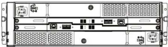
The disk processor enclosure (DPE) is a 2U component with 25 2.5" drive slots. Verify that you have received all of the DPE components, including cables, bezel, and rail kit.
| Component | Image |
| 2U, 25-drive disk processor enclosure (DPE) | 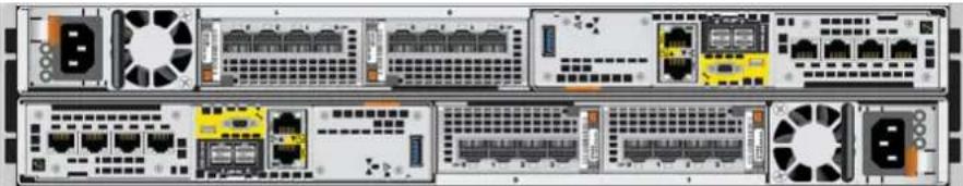 |
| Tool-less rails | 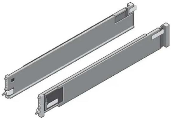 |
| Component Image | |
| Power cords | 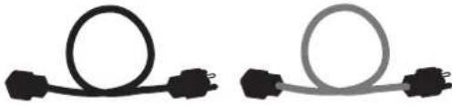 |
| Bezel for disk processor enclosure (1) | 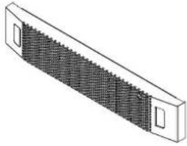 |
Record the product serial number from the DPE
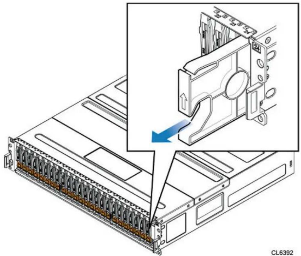
The PSNT for the 25-slot DPE is a black pull-out tag that is located between the drives in slots 16 and 17.
Figure 1 Location of the product serial number tag
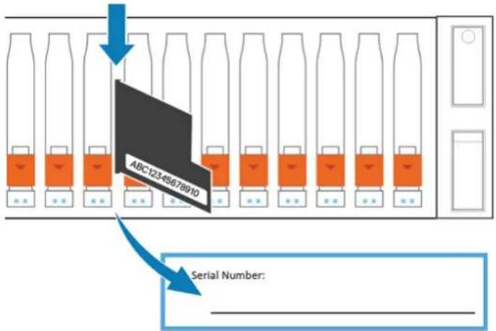
Pull the tag out and record the product serial number from the tag on the Configuration Worksheet. The product serial number is three letters followed by 11 numbers. After recording the information, return the tag to its inserted position.
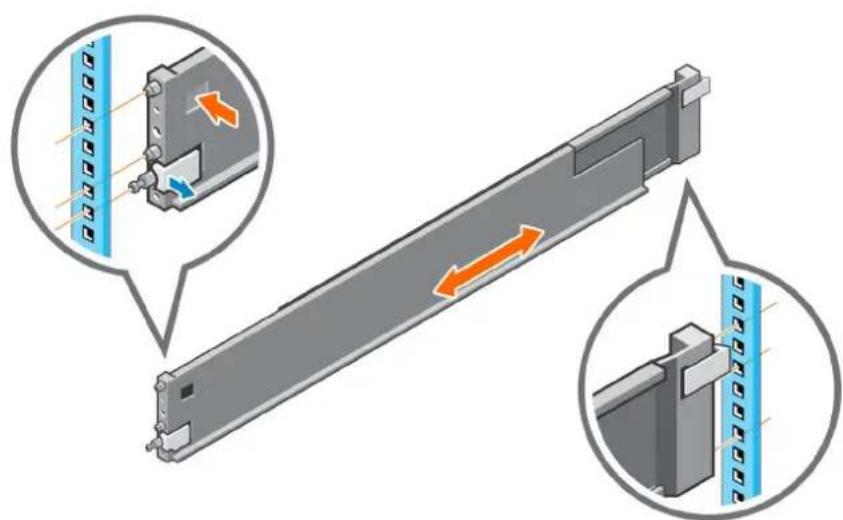
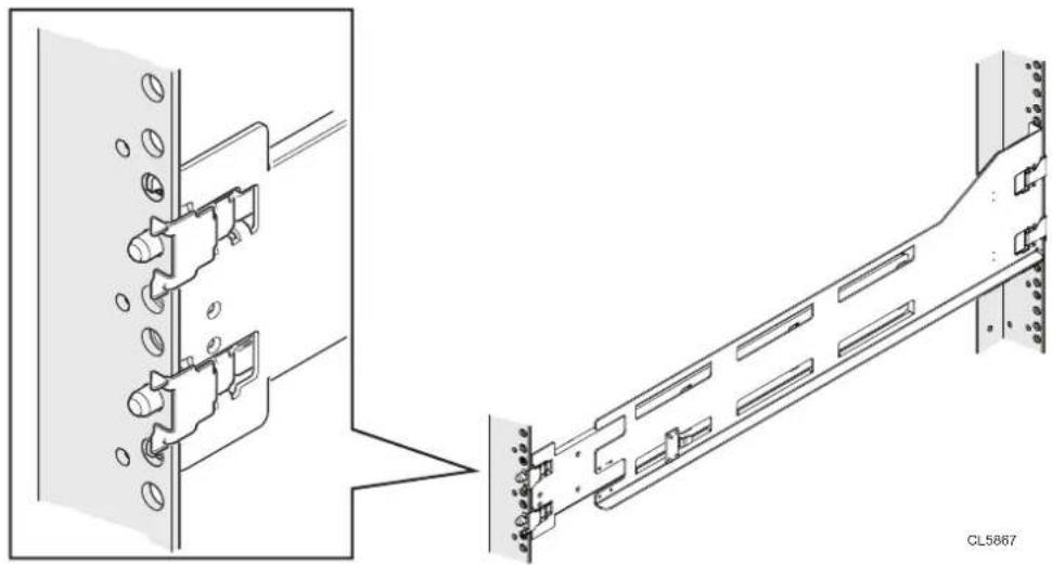
Install the rails in the cabinet
This task describes the procedure to install one rail. After installing one rail, repeat the procedure for the other rail. The procedure is the same for both the left and right rail. You can install the rails into either a square or round hole rack.
Procedure
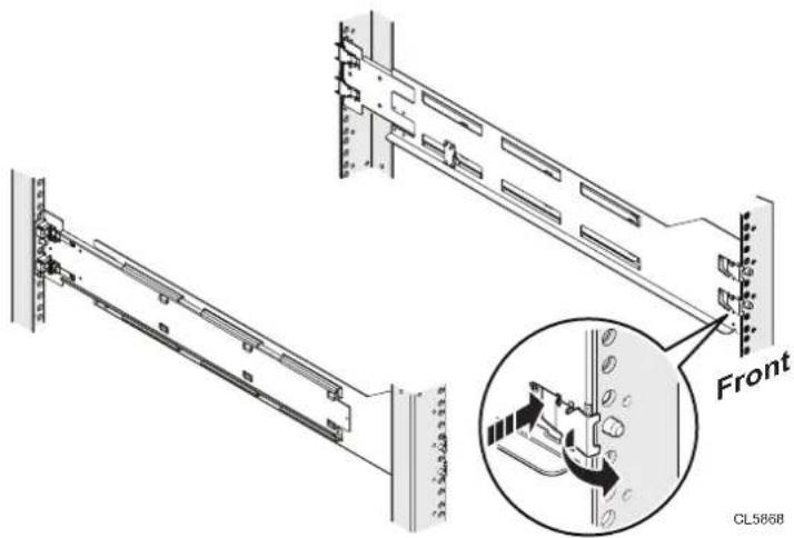
- Position the rail end piece so the label FRONT is located at the front of the rack and facing towards the inside of the rack, while orienting the rear of the rail to align level with the holes on the rear of the rack.
- From the rear of the rack, pull the rail straight back until the latch is locked.
-
To install the front end piece of the rail, press the blue latch release button until the latch rotates open.
-
Pull the rail forward until the pins slide into the holes on the front of the rack, then release the latch to secure the rail in place.
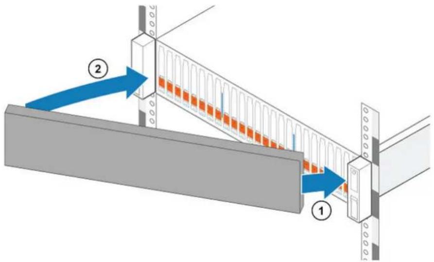
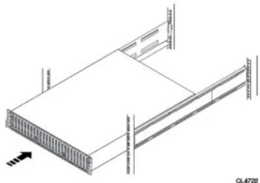
Figure 2 Installing the rails
natural_image
Diagram of a mechanical component with directional arrows indicating movement, shown in two circular views (no text or symbols present)- Repeat for the other rail.
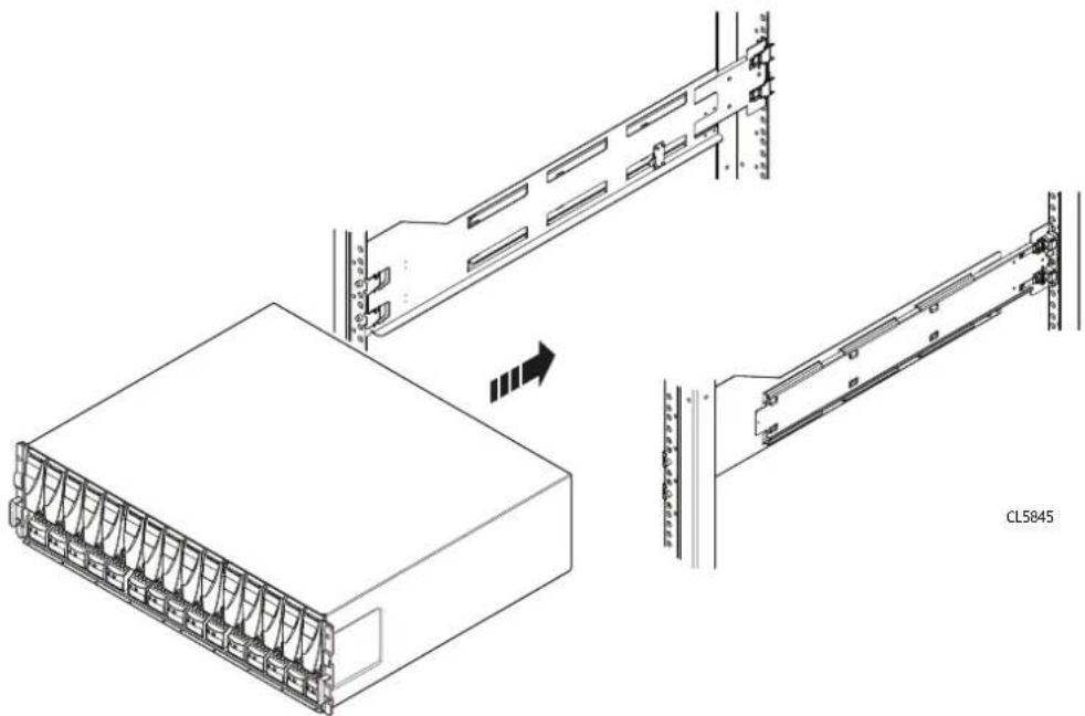
Install the DPE on the rails
CAUTION
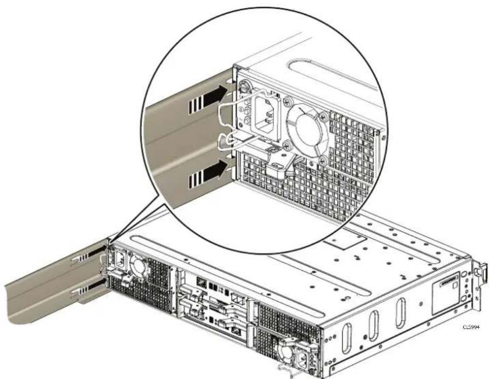
The enclosure is heavy and should be installed into or removed from a rack by two people. To avoid personal injury and/or damage to the equipment, do not attempt to lift and install the enclosure into a rack without a mechanical lift and/or help from another person.
- Lift the enclosure and slide it onto the rails from the front of the cabinet.
- Push the system into the rack until the slam latches engage and lock the system into the rack.
Ensure that the enclosure is flush with the front of the rack, fully seated in the cabinet, and does not slide out.
Figure 3 Installing the system in the enclosure
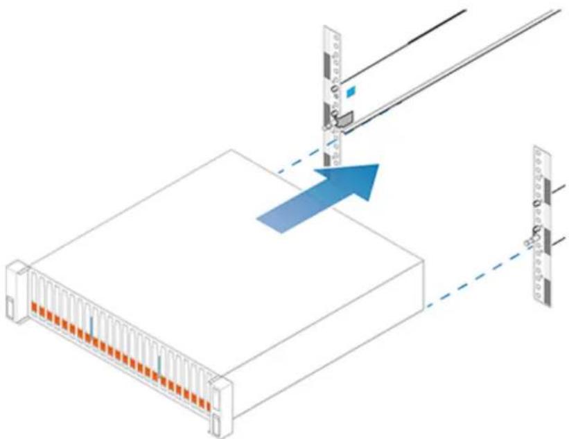
natural_image
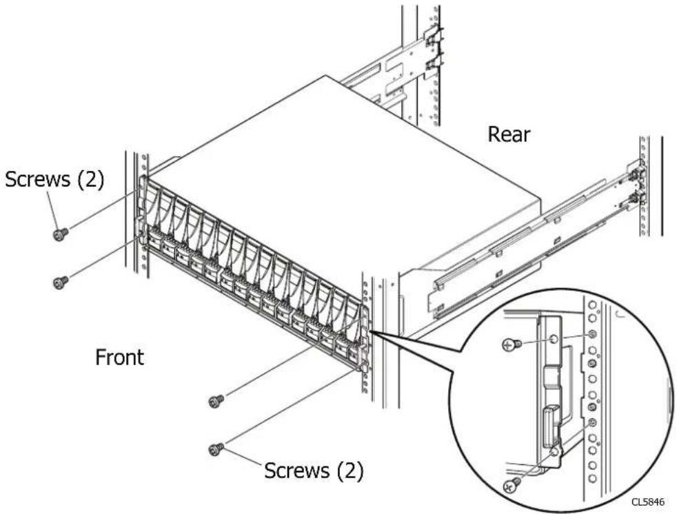
Diagram showing a server rack with orange connectors and a blue arrow indicating a process or connection (no text or symbols present)Secure the system in the cabinet
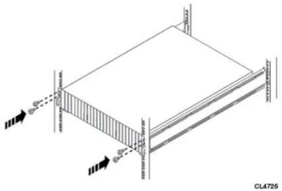
Procedure
- If securing the system for shipment in the cabinet or in other unstable environments, locate the hard mount captive screw under each latch and tighten using a #1 Phillips screwdriver.
Figure 4 Securing the system in the cabinet
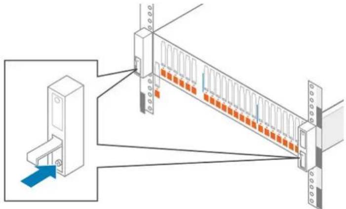
natural_image
Diagram of a server rack with orange connectors and connection points, showing internal structure and connection to a device (no text or symbols present)Attach the storage processors to the network
Procedure
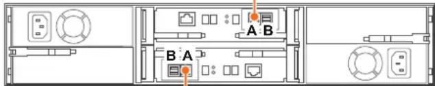
- Locate two bulk Category (CAT) 5, 5e, 6, 6a or better Ethernet cables.
- Connect two Ethernet cables from the LAN to the 1 Gb RJ45 management ports from which you will configure the system. This will be one port on each storage processor.
Note
The SP A and SP B network management ports must be connected on the same subnet. In general, both SPs should have mirrored configurations in order to provide failover.
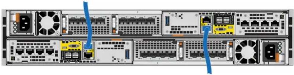
Figure 5 Cabling the storage processors to the network
natural_image
Front view of a rack-mounted server with multiple ports and connectors (no visible text or labels)Note
Additional information about the ports and cabling is in the Hardware Information Guide, available on the Unity Info Hub at http://bit.ly/unityinfohub or on Online Support (https://support.emc.com/products/39949).
Install optional DAEs
If you are installing one or more optional DAEs, see Unpack the (optional) disk-array enclosures on page 25 for installation instructions.
If you are not installing an optional DAE, continue to the next section.
Connect power to the DPE
Before you begin
All components must be racked and the network cabling completed before connecting the storage system to power and booting the system.
Procedure
- Verify that the cabinet circuit breakers are in the On position and that power is connected to the cabinet.
Note
No power cables should be connected to the PDUs at this time.
- Attach a double-sided Shut Down Procedure cable label to each power cable using the tie wraps included in the Accessory Kit.
Note
Attach each label close to the end of the power cable where it plugs into the DPE.
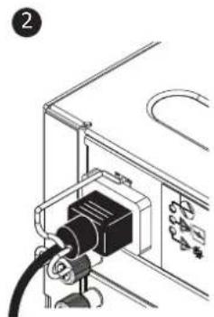
- Plug each DPE power cable into each SP assembly's power supply unit.
The power cable to SP assembly A is gray. The power cable to SP assembly B is black.
-
Secure each power cable to the system component with the cable retention bail on the power supply unit.
-
Connect the DPE to the power distribution unit as follows:
a. Connect the power supply for SP assembly A, shown in gray, to PDU A.
b. Connect the power supply for SP assembly B, shown in black, to PDU B.
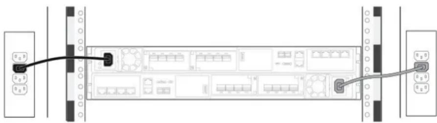
Figure 6 Cabling the DPE to the PDU
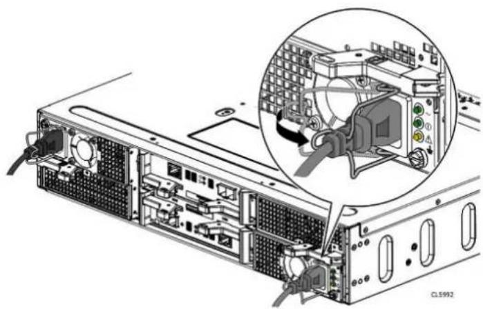
natural_image
Diagram of a server rack with ports and connectors, showing internal components and cable routing (no text or labels)- Bundle and secure the cables as necessary with tie wraps.
- If your storage system has been installed in a cabinet, place the single-sided adhesive backed Shut Down Procedure label included in the Accessory Kit on the back of the cabinet door. Otherwise, place this label in a location that is visible while viewing the storage system from the rear.
- Monitor the system as it powers up. It takes approximately 10-15 minutes for the system to power up. The LEDs show the progress of system activation. Green, blue, and amber activity lights blink during the startup sequence. Review the next section for information on the power up states.
Power up optional DAEs
If you installed one or more optional DAEs, attach the power cables. See Connecting power to the DAE on page 38 for instructions on powering up a DAE.
If you are not installing an optional DAE, continue to the next section.
Verify status LEDs
The system should be available in approximately 15 minutes.
This section calls out only the LEDs that you need to verify to ensure that the system powered up correctly.
Note
The Unity Hardware Information Guide provides more details on all system LEDs.
The array is powered up and ready to run the Connection Utility when the SP Fault LED shows intervals of amber for one second and blue for three seconds. If the system is on a network with a DNS server and DHCP, the management IP address can be assigned automatically. When it is assigned, the SP Fault LED is solid blue. Ensure that the power-up is complete and that the system is ready before you continue.
DPE rear status LEDs
Figure 7 Storage processor assembly LEDs

Table 1 Storage processor assembly LEDs
| LED Location State Description | |||
| Storage processor assembly fault | 1 | Amber Fault has occurred. | |
| Blue A management IP address has been assigned. | |||
| Amber or blue blinking | System is booting. | ||
| Blue and amber alternating (blue for 3 seconds) | System not initialized. A management IP address has not been assigned. | ||
| Blue and amber alternating at one second intervals | Storage processor assembly in Service Mode. | ||
| Off No fault has occurred, normal operation. | |||
| Storage processor assembly power | 2 | Green Storage | processor assembly is on (main power). |
| Green blinking | Storage processor assembly is initializing a serial over LAN session (Standby Mode). | ||
| Off Storage processor assembly is off. | |||
DPE front status LEDs
Figure 8 DPE and disk drive LEDs
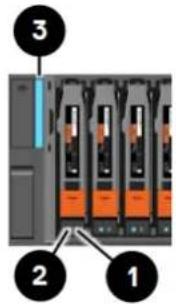
Table 2 DPE and disk drive LEDs
| LED Location State | Description | ||
| Disk drive fault Amber Fault has occurred. | |||
| Off No fault has occurred, normal operation. | |||
| Disk drive active Blue Disk drive activity. | |||
| Off Disk drive is powered off. | |||
| DPE fault/power Blue Power is on. No fault has occurred, normal operation. | |||
| Amber Power is on. Fault has occurred within the enclosure. | |||
| Off Power is off. | |||
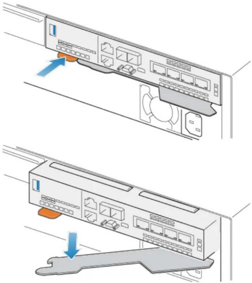
Installing the front bezel
CAUTION
Remove the plastic protective strip from the front of the bezel prior to placing the system into operation. Failure to do so will cause the system to overheat.
Procedure
- If present, remove the plastic protective strip from the front of the bezel.
- Align the bezel with the enclosure.
- Gently push the bezel into place on the cabinet until it latches.
- If the bezel has a lock, insert the key that shipped with your enclosure into the lock, and turn the key to lock the bezel.
Figure 9 Installing the front bezel
Connect a Windows-based computer to your storage system
Note
At the end of the power-up process, the SP Fault LED blinks in intervals of amber for one second and then blue for three seconds, indicating that the system is ready to run the Connection Utility.
You must connect a Windows-based computer to your system directly or remotely over a subnetwork. This computer will be used to continue setting up your system and must be on the same subnet as the storage system to complete the initialization.
NOTICE
Check to see if there is security software running on your workstation/laptop such as Cisco Security Agent or McAfee Host Intrusion Prevention Service that may prevent the initialized system from being detected. If there is, disable it (Windows Services) before running the initialization.
The system management ports support both IPv4 and IPv6. You can assign an IP address to a system in the following ways:
- If you are running the storage system on a dynamic network that includes a DHCP server and a DNS server, the management IP address can be assigned automatically.
- If you are not running the storage system in a network that supports DHCP or you would rather manually assign a static IP address, you must install and run the Connection Utility on the Windows-based computer.
Dynamic IP addresses (DHCP) should not be used for any components of the EMC Secure Remote Services Virtual Edition (ESRS VE) servers, Policy Manager servers, or managed devices.
NOTICE
If you use DHCP to assign IP addresses to any EMC Secure Remote Services (ESRS) components (ESRS Virtual Edition servers, Policy Manager, or managed devices), they must have static IP addresses. Leases for the IP addresses that Dell EMC devices use cannot be set to expire. It is recommended that you assign static IP addresses to those devices you plan to have managed by ESRS.
Automatically assigning a dynamic storage system management port IP address
Assigning an IP address to a storage system management port dynamically requires the following:
• Network DNS server (with dynamic DNS services enabled)
- Network DHCPv4 server and/or a DHCPv6 server and/or a router advertising DNS servers
- Connectivity between the storage system, the DHCP server, and the DNS server
The DHCP server must be configured to automatically register DHCP clients with Dynamic DNS services. By default, storage systems are configured to use DHCP for IP assignment and will accept an IP address offered by a network DHCP server.
Perform the following steps to automatically assign an IP address to your storage system management port:
Procedure
-
After you power up the storage system, check the SP Fault LED.
-
If the SP Fault LED is solid blue, a management IP address has been assigned.
-
If the SP Fault LED is solid blue for three seconds and then flashes amber for one second intervals, no management IP address has been assigned. Check the connectivity between the system, the DNS server, and the DHCP server.
-
Open a web browser and access the Unisphere management interface specifying the following as a URL in the browser's address bar: serial_number.dns_zone
where
| URL string | Description |
| serial_number Serial number of your storage system. You can find this in the packing materials that came with your system (for example, FNM00131800283). It is also on the PSNT tag on the front of the DPE. | |
| dns_zone Network DNS zone on which the storage system is located (for example, mylab.emc.com). | |
Based on the examples provided in this table, the URL to the storage system would be FNM00131800283.mylab.emc.com.
Note
If a certificate error appears, follow the instructions in your browser either to bypass the error or to install the self-signed storage system certificate. For more detail about your storage system certificate, refer to the EMC Unity Security Configuration Guide.
-
Log in with the default username and password.
-
Username: admin
- Password: Password123#
The Unisphere Initial Configuration wizard launches.
- Continue with the steps in the Unisphere Initial Configuration wizard to accept the license agreement, configure, and update the software on your system.
The Unisphere Initial Configuration wizard online help provides information about the steps remaining to accept the license agreement, configure, and update the software on your system.
- Confirm that the SP Fault LED is now out.
This provides an indication that all operating system software has booted and SP is ready for I/O.
Manually assigning a static storage system management port IP address
To manually assign a static IP address for the storage system management port, you must install and run the Connection Utility on a Windows-based computer. The Connection Utility assigns a network address to the storage system.
Download and install the Connection Utility software
Procedure
- Download the Connection Utility installation program from the Dell EMC Online Support website (https://support.emc.com/products/39949), under the Downloads selection on the menu bar of the product page for your storage system.
- Install the Connection Utility software on a Windows computer.
To use the Auto Discover method, install the Connection Utility on a computer in the same subnet as the storage system's management port.
- Launch the Connection Utility.
In Windows: C:\Program Files\DELL EMC\Unity linkedUtility
Note
The Connection Utility automatically sets the displayed language based on the settings of the computer. To change the language displayed in the Connection Utility, select the language from the list under Change language:.
Run the Connection Utility
Before you begin
Obtain the following information:
- Serial Number: Unique identifier associated with the storage system (printed on a tag located on the system). This identifies your system when you use the Connection Utility to discover storage systems on a subnet. When you register your system online, this value is the Product ID.
- System name: Name that you will be assigning to the storage system.
- IP address: Management IPv4 or IPv6 address through which Unisphere connects to the storage system.
- Subnet mask: For IPv4 management addresses, the subnet mask is an IP address mask that identifies the range of IP addresses in the subnet where the storage system is connected.
- Subnet prefix length: For IPv6 management addresses, the subnet prefix length is the number of significant bits in the address that will be used for routing purposes.
- Gateway address: IP address of the default gateway for the management interface. The gateway is the IP address of the router or node used to communicate outside the local subnet.
Run the Connection Utility from a host attached to the same subnet as your storage system. Doing so lets the Connection Utility automatically detect the new storage system. If you are unable to run the Connection Utility from the same subnet, you can still manually configure the connection.
Procedure
-
On the Welcome screen, select one of the following methods to configure your system, and then click Next:
-
Auto Discover - Use this method if you are running the Connection Utility from a host on the same subnet as your storage system. This method automatically discovers unconfigured storage systems on your local network and sends the configuration file directly to the storage system.
-
Manual Configuration - Use this method if you are running the Connection Utility from a host that is not on the same subnet as your storage system. This method enables you to create a configuration file that you can save to a USB flash drive. You then insert the flash drive into the USB port on the storage system, and the storage system automatically reads the configuration from the USB drive.
-
[Applies to Auto Discover mode only] From the list of automatically discovered systems, select the system you want to configure, and then click Next. Note: If you do not see the system listed on the screen, try clicking Discover to restart the discovery process. If the problem persists, refer to troubleshooting instructions.
-
On the Configure screen, specify the following:
- Name - A meaningful name for this system. You can specify a name up to 32 characters. It can only contain alpha-numeric characters and a dash. It cannot contain any space characters, underscores, or begin and end with a dash.
- In the Management IPv4 Address and Management IPv6 Address sections, select the options you want, specify relevant information, and then click Next.
-
Review the configuration information, and then do the following based on the mode you selected:
-
For Auto Discover mode, click Start to apply the configuration on the storage system.
• For Manual Configuration mode:
a. Click Save to USB drive. Ensure that you save the configuration file to the root directory level of the USB drive.
b. Click Next to identify the location of the port on your storage system.
c. Insert the USB drive into one of the available USB ports on either SP.
The storage system will automatically detect the USB drive and apply the network connection information. This process may take up to 10 minutes.
When successfully completed, a response file (iw_resp.txt) is written back to the USB drive.
- Click Finish.
- Confirm that the SP Fault LED is solid blue, which indicates that the system's IP address has been set.
After you finish
In a web browser, access Unisphere by specifying the URL: http://
Where,
Note
Refer to the Configuration Worksheet for information on the user credentials you must use the first time you log on.
The Initial Configuration Wizard launches the first time you access Unisphere. Refer to the Configuration Worksheet and Unisphere Online Help for more information on configuring and start using your system.
Unpack the (optional) disk-array enclosures
Disk-array enclosures (DAEs) provide additional storage. The types of DAEs available are:
• 3U 15 disk 3.5" drive DAE
• 2U 25 disk 2.5" drive DAE
DAEs are optional. If you have one or more DAEs in the system, verify that you have received all of the DAE components, including cables, bezel, rail kit, and mounting screws.
15-drive DAE container contents
Verifying shipping package contents
Confirm that you received all necessary equipment needed to install the new 15-drive DAE.
Verify that you received the following:
| Component Quantity | ||
| Disk-array enclosure (DAE) Front view | 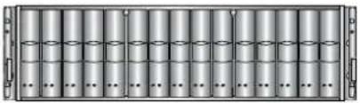 | 1 |
 | ||
| Rear view CL5665 | ||
| Snap in rail kit | 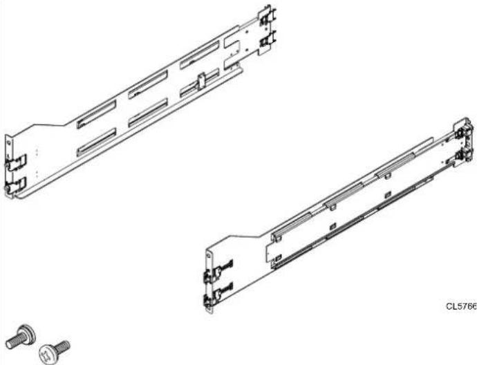 | 1 (includes 2 rails and 6 screws) |
| Power cords (AC or DC) AC power cords | 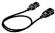 | 2 |
| DC power cords | ||
| Bezel for disk-array enclosure (with key) |  | 1 |
| SAS cables (either 1 meter or 2 meter copper) that connect disk-array enclosures to each other (1 meter cables) or to DPE (2 meter cables) | 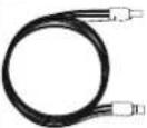 | 2 |
25-drive DAE container contents
Verifying shipping package contents
Confirm that you received all necessary equipment needed to install the new 25-drive DAE.
Verify that you received the following:
| Component Quantity | ||
| Disk-array enclosure (25-drive DAE) | Front view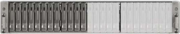 Rear view Rear view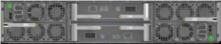 | 1 |
| Rail kit, includingSnap-in rails (2)Screws (3 per rail) | 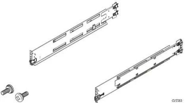 | 1 |
| Power cords 2 | 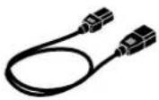 | |
| Bezel for disk-array enclosure (with key) | 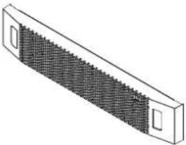 | 1 |
| mini-SAS HD cables (either 1 meter or 2 meter copper) that connect disk-array enclosures to each other (1 meter cables) or to DPE (2 meter cables) | 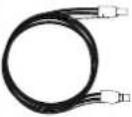 | 2 |
Install the disk array enclosure
There are two types of DAEs. One is a 3U 15 disk 3.5" drive DAE. The other is a 2U 25 disk 2.5" drive DAE. DAEs are optional. The installation procedures are slightly different for each.
Install 15-drive DAE
Installing snap-in rails in the cabinet
Note
The snap-in rails are dedicated left and right, and cannot be interchanged. The front edge of each rail is stamped L or R for left or right side when the rail faces the cabinet front.
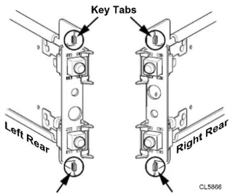
The snap-in rails have two key tabs at the top and bottom edge on the rear of each rail. The key tabs ensure that the rails are installed in the appropriate 2U space.
Procedure
- From the rear of the cabinet, insert the two key tabs into the holes of the 2U-space on the rear cabinet channel.
Figure 10 Key tabs at rear rail top and bottom edge
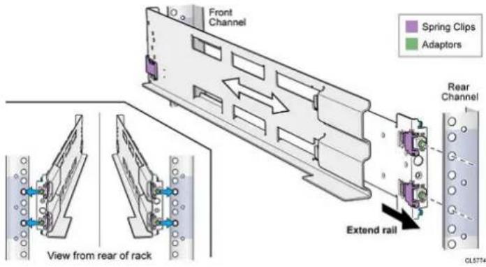
Note
As the key tabs and adaptors are pushed into the rear mounting holes, the spring clips will ride over the cabinet channel and snap into place.
- Holding the rail extended, push the key tabs and the adaptors into the rear mounting holes until the spring clips snap into place on the outside of the rear cabinet channel.
Figure 11 Aligning the rear adaptors (left rear of cabinet shown)
natural_image
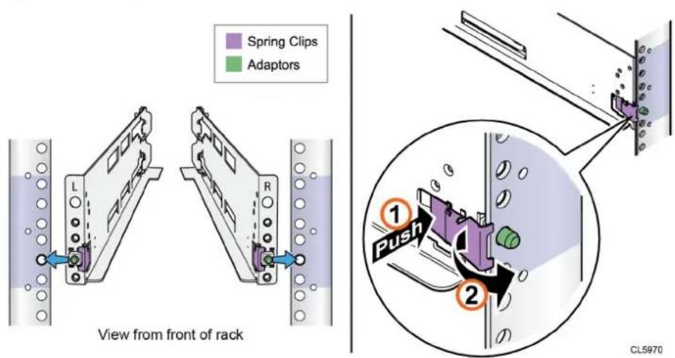
Technical diagram showing a mechanical assembly with two views: one close-up of a component and another enlarged detail (no text or symbols)- At the front of the cabinet, making sure the rail is level, pull it forward and align the rail adaptor with the mounting hole in the channel. Push in on the spring clip while pulling forward on the rail. When the spring clip is forward of the front cabinet channel, and the adaptor is in the mounting holes, release the spring clip so it holds the rail in place.
CAUTION
Ensure the spring clip is securely attached to the channel. It may be necessary to push in on the clip to assist in snapping it into place.
Figure 12 Securing the Spring Clips
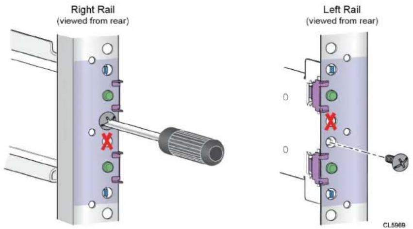
- From the rear of the cabinet, secure the rail in place using one M5 screw on each rail.
Figure 13 Installing the M5 Screw
Installing the DAE on the rails
WARNING
The enclosure is heavy and should be installed into or removed from a rack by two people. To avoid personal injury and/or damage to the equipment, do not attempt to lift and install the enclosure into a rack without a mechanical lift and/or help from another person.
Procedure
- With help from another person, lift the enclosure and, from the front of the cabinet/rack, slide the enclosure onto the rails.
Figure 14 Sliding the enclosure onto the rails
natural_image
Technical line drawing of a server rack with internal components and an arrow indicating assembly (no text or symbols)- Once the enclosure is completely seated into the rear tabs, secure the front of the enclosure to the front vertical channels with four screws (two per side), but do not tighten the screws until they are all in place.
Figure 15 Securing the front of the enclosure
Install 25-drive DAE
Installing the rails in the cabinet
Note
The snap-in rails are dedicated left and right, and cannot be interchanged.
Procedure
- Orient the rails. Face the front of the cabinet when orienting the left and right rail placement. The front edge of each rail is stamped L or R.
- From the rear of the cabinet, insert the adapters into the holes on the rear rack channel with the rail extended as shown in Figure 16 on page 32.
- Push the rail into the rear mounting holes until the spring clips snap into place on the outside of the rear channel.
CAUTION
Ensure the holes on the rail line up with the holes on the cabinet. This will ensure proper alignment of the rails. Also, check that the rails are level and using the same cabinet Unit markers from front to rear. Ensure you are using the same unit markers from the front of the cabinet to the rear of the cabinet.
Figure 16 Push rail into rear channel mounting holes
- From the rear of the cabinet, secure the rails in place using one M5 screw on each rail.
Figure 17 Installing the M5 Screw
- Working from the front of the cabinet, align the adaptor with the mounting hole on the front of the rack as shown in Figure 18 on page 33.
CAUTION
Ensure the holes on the rail line up with the holes on the cabinet. This will ensure proper alignment of the rails. Also, check that the rails are level from front-to-back and left-to-right. Ensure you are using the same unit markers from the front of the cabinet to the rear of the cabinet.
- Push in on the spring clip while pulling the rail forward. When the spring clip is forward of the front rack channel, and the adaptor is in the mounting holes, release the spring clip so it holds the rail in place.
CAUTION
Ensure the spring clip is securely attached to the channel. It may be necessary to push in on the clip to assist in snapping it into place.
Figure 18 Securing rail to front channel
Installing the DAE on the rails
CAUTION
The enclosure is heavy and should be installed into or removed from a rack by two people. To avoid personal injury and/or damage to the equipment, do not attempt to lift and install the enclosure into a rack without a mechanical lift and/or help from another person.
Do not install the enclosure without the rear rail screws installed and fully tightened. If the screws are not installed and tightened, the rails could rotate out of position, possibly causing the enclosure to fall, causing damage to the DAE and causing personnel injury.
Procedure
- With help from another person, lift the enclosure and, from the front of the cabinet/rack, slide the enclosure onto the rails.
Figure 19 Sliding the enclosure onto the rails
natural_image
Technical line drawing of a server rack with ventilation ducts and mounting brackets (no text or symbols)When the enclosure slides to the back of the cabinet, the rear tabs on the rails insert into the notches in the rear of the enclosure. The tabs secure and support the rear of the enclosure.
Figure 20 Rail tabs securing the rear of the enclosure
natural_image
Technical diagram of a server rack with an inset close-up showing internal components (no text or symbols)- Secure the front of the enclosure to the front vertical channels with four screws (two per side), but do not tighten the screws until they are all in place.
Figure 21 Securing the front of the enclosure
natural_image
Technical diagram of a structural panel with directional arrows and dimension labels (no readable text or symbols)Cabling the DPE to a DAE
If you have one or more DAEs, cable the DAEs to the DPE back-end ports so that the storage is available in the system.
Ensure that the DAE is located close enough to route and connect to the DPE using the two-meter DPE-to-DAE interconnect cables. Five-meter and ten-meter interconnect cables are available when connecting enclosures across multiple racks.
Note
General DAE back-end bus configuration rules:
- Maximum number of enclosures per bus is 10.
- Maximum number of drive slots per bus is 250, up to specific system limitations for drive slots.
- For best performance, it is recommended that you evenly distribute DAEs across the available back-end buses.
Consider the maximum number of drives that can be installed in the storage system model. DAEs can be added to the system while the operating system is active, and up to the DAE and drive slot limit for the storage system. DAEs or drive slots that are over the system limit cannot operate in the system.
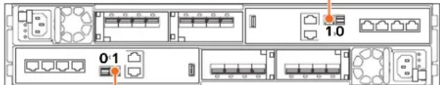
The storage processors connect to the DAEs with mini-SAS HD cables. The cables connect LCCs in the DAEs of a storage platform in a daisy-chain topology. The mini-SAS HD ports on the storage processors in the DPE are labeled 0 and 1. Mini-SAS HD port 0 is connected internally to the SAS expander that connects the drives on the front of the DPE.
Each DAE supports two redundant connections to the DPE: LCC A and LCC B.
It is recommended that you connect the first optional DAE to the mini-SAS HD output port 1 of each storage processor. This connection creates back-end bus 1 (BE1) and designates this DAE as enclosure 0 of this bus. The address of this enclosure is BE1 Enclosure 0. In a two back-end bus system, it is recommended that you connect the second optional DAE to the mini-SAS HD port 0 of each storage processor.
DAE load balancing
If your system has several optional DAEs, you can daisy-chain them within that bus. However, it is recommended that you balance each bus. In other words, optimize your environment by using every available bus, and spread the number of enclosures and
drives as evenly as possible across the buses. The rule of load or bus balancing is applied to all DAEs.
Cabling the first optional DAE to create back-end bus 1
Connect the first optional expansion DAE to port 1 of the DPE to create back-end bus 1 (BE1) and designate this DAE as enclosure 0 of this bus. We refer to the address of this enclosure as BE1 Enclosure 0 (1_0).
To prepare for this cabling task:
- Locate the mini-SAS HD cables to be used to connect to the newly installed expansion DAE. Typically these cables are two-meters long. You use longer cables, typically five-meters or eight-meters, to connect enclosures located in different racks. Cables are shipped without labels attached. The cables and ports are not colored.
- Locate the sheet of cable labels provided.
Orient the cable connectors as described in the procedure that follows, making sure that you do NOT connect:
• A DPE expansion port 0 to another DPE expansion port 0
• Any A-side ports to B-side ports
Procedure
- Label a pair of mini-SAS HD cables.
- Connect port 1 on SP A in the bottom slot of the DPE to port A on the link control card (LCC A) in the bottom of the DAE.
- Connect port 1 on SP B in the top slot of the DPE to port A on the link control card (LCC B) in the top of the DAE.
Figure 22 Cabling one DPE to one 25-drive DAE
Cabling the second optional DAE to create back-end bus 0
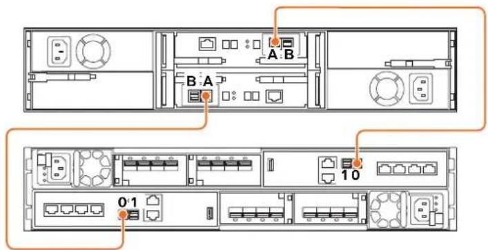
Connect the second optional expansion DAE to the DPE expansion port 0 to extend back-end bus 0 (BE0) and designate this DAE as enclosure 0 of this bus. We refer to the address of this enclosure as BE0 Enclosure 0 (0_0).
Note
When cabling the 15-drive DAE LCC SAS ports, ensure that the cables do not overlap behind the DAE.
Procedure
- Label a pair of mini-SAS HD cables.
- Connect port 0 on SP A in the bottom slot of the DPE to port A on the link control card (LCC A) in the bottom of the DAE.
- Connect port 0 on SP B in the top slot of the DPE to port A on the link control card (LCC B) in the top of the DAE.
Figure 23 Cabling a DPE to a second 25-drive DAE
If you need to cable more than two optional DAEs, refer to the Unity Installation Guide.
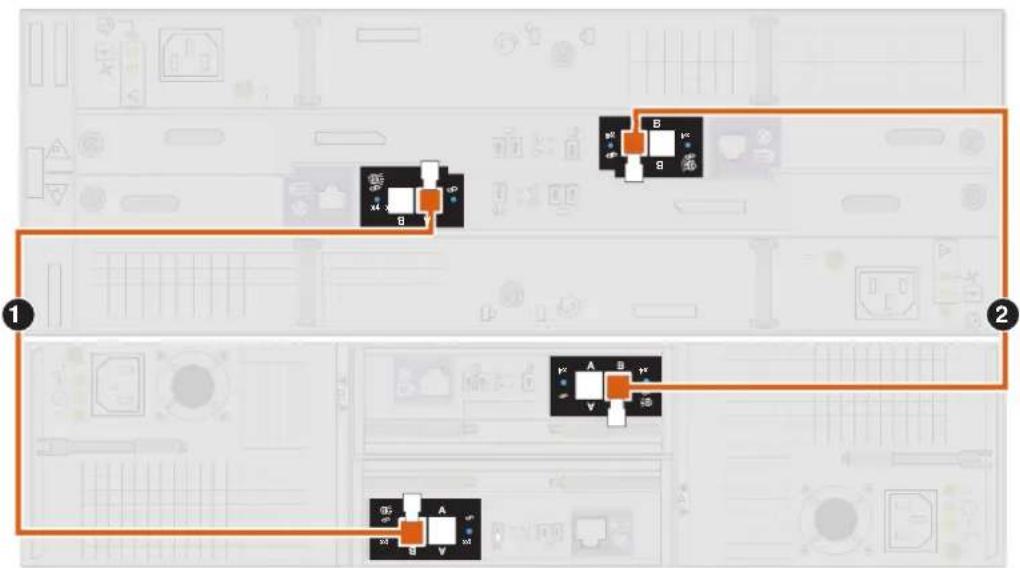
Cabling an expansion DAE to an existing DAE to extend a back-end bus
Connect the optional expansion DAE to the last installed DAE in the back-end bus to extend to the new DAE.
Note
When cabling the 15-drive DAE LCC SAS ports, ensure that the cables do not overlap behind the DAE.
Procedure
-
Label a pair of mini-SAS HD cables.
-
Connect port B on the link control card (LCC A) of the lower-numbered DAE to port A on the link control card (LCC A) of the higher-numbered DAE.
LCC A is on the lower portion of the DAE.
- Connect port B on the link control card (LCC B) of the lower-numbered DAE to port A on the link control card (LCC B) of the higher-numbered DAE.
LCC B is on the upper portion of the DAE.
Example 1 Connect the DAE to another DAE
Figure 24 25-drive DAE extended to a 15-drive DAE
flowchart
graph TD
    A["Input Port 1"] --> B["Control Button 1"]
    B --> C["Output Port 2"]
    C --> D["Control Button 2"]
    D --> E["Output Port 3"]
Connecting power to the DAE
Procedure
- Verify that the cabinet circuit breakers are in the On position and that power is connected to the cabinet.
- Connect the power cables to the optional DAEs.
Figure 25 Connecting power cables to the 3U, 15-drive DAE
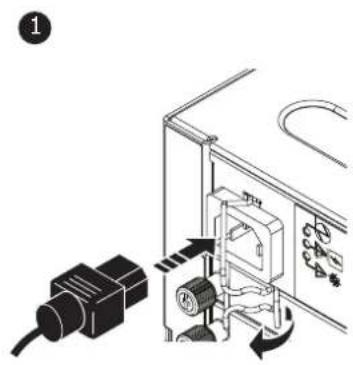
natural_image
Diagram of a plug inserted into a device housing (no text or symbols visible)CL5765
Figure 26 Connecting power cables to the 2U, 25-drive DAE
natural_image
Technical illustration of a server rack with an inset showing internal components (no text or symbols)- Secure each power cable to the power supply with the cable retention bail.
- Connect the power to the each DAE as follows:
a. Connect the power cable for LCC A to PDU A.
b. Connect the power cable for LCC B to PDU B.
The enclosures power up immediately once the cable is connected.
- Bundle and secure the cables as necessary with tie wraps.
Installation Procedures
CHAPTER 2
Service Procedures
This document describes how to replace parts or add new parts to a system.
Before you service the system, ensure that you have received the new part and have correctly identified its intended location in the system. Go to the Unisphere Service section for instructions on how to identify failures, order new parts and safely handle hardware components.
When servicing the system, only add or replace one component at a time. New hardware added while simultaneously servicing other components may not be recognized by the system and can cause errors.
Note
Review the information in Safety precautions for handling replaceable units on page 121 before handling replaceable parts.
- Replace a faulted disk in the DPE....42
- Add a new disk in the DPE....44
- Replace a power supply 46
- Replace an embedded module....49
- Add a 4-port card....56
- Replace a 4-port card....61
- Add an SFP 69
- Replace a faulted SFP....70
- Replace an I/O module....72
- Add an I/O module....76
- Replace a fan module....78
- Replace a dual inline memory module (DIMM) 88
- Replace an M.2 SSD 96
- Replace an SP assembly....106
Replace a faulted disk in the DPE
Take the following actions to remove a faulted disk and install the replacement disk into the DPE.
Identifying and locating the faulted part in Unisphere
Before you replace a faulted part, locate its placement within the storage system. Procedure
- In Unisphere, select System View.
- Select the Enclosures page.
- Locate the faulted part marked orange, and displayed in the Enclosures view.
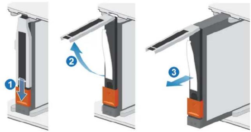
Remove a faulted 2.5" disk
Procedure
- Push down on the orange button to release the latch.
- Remove the disk from the slot.
Figure 27 Removing a 2.5" disk
- Place the disk on a static-free surface.
Install a 2.5" disk
Note
If you are installing multiple disks in a system that is powered up, wait at least 10 seconds before sliding the next disk into position.
Procedure
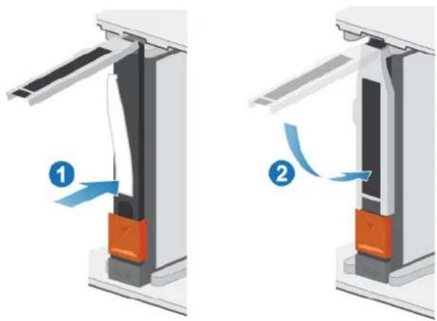
- Align the disk with the guides in the slot.
- With the latch fully opened, gently push the disk into the slot.
The latch begins to rotate downward when it meets the enclosure. -
Push the orange button until the disk is fully seated in the slot.
-
Push the latch down until it locks into place
The activity light flashes to indicate that the spin-up sequence has begun.
Figure 28 Installing a 2.5" disk
natural_image
Two-step diagram showing fluid flow between a mechanical component, labeled 1 and 2 with arrows indicating direction (no text or symbols beyond labels)Verifying the operation of the new part in Unisphere
Verify that the new part is recognized by your system, and operating correctly.
Procedure
-
In Unisphere, select System View.
-
On the Summary page, confirm that the system status is OK.
-
Select the Enclosures page.
-
Verify that the part appears with the OK status in the enclosure view. You may need to refresh Unisphere by clicking on the refresh icon next to the Enclosures view.
If the system health monitor shows the part as faulted, contact your service provider.
Returning a faulted part
We appreciate the return of defective material within 5 business days (for US returns). For International customers, please return defective material within 5-10 business days. All instructions and material required to return your defective part were supplied with your good part shipment.
Procedure
- Package the faulted part in the shipping box that contained the replacement part, and seal the box.
- Ship the failed part to your service provider as described in the instructions that were included with the replacement part.
- (Optional) For more information about returning customer-replaceable parts, from Unisphere, click Support > Replace Disk Drives, Power Supplies, and Other Parts > Return a Part to display the part return instructions.
If your screen does not show the Return a Part option, contact your service provider for instructions on what to do next.
Add a new disk in the DPE
Take the following actions to add a new disk in the DPE.
Removing the front bezel
Procedure
- If the bezel has a lock, insert the key that shipped with your enclosure into the lock, and turn the key to unlock the bezel.
- Press the two latch buttons on the bezel surface to release the bezel from the cabinet.
- Pull the bezel off the cabinet and put it on a clean, static-free surface.
Remove a disk filler module
Procedure
- Insert your finger into the cutout on the disk filler module.
- Pull the filler module out of the slot.
Figure 29 Removing a disk filler module
Install a 2.5" disk
Note
If you are installing multiple disks in a system that is powered up, wait at least 10 seconds before sliding the next disk into position.
Procedure
- Align the disk with the guides in the slot.
-
With the latch fully opened, gently push the disk into the slot.
The latch begins to rotate downward when it meets the enclosure. -
Push the orange button until the disk is fully seated in the slot.
-
Push the latch down until it locks into place
The activity light flashes to indicate that the spin-up sequence has begun.
Figure 30 Installing a 2.5" disk
natural_image
Two mechanical assembly diagrams showing fluid flow or movement between components, labeled 1 and 2 (no text or symbols present)Verifying the operation of the new part in Unisphere
Verify that the new part is recognized by your system, and operating correctly.
Procedure
- In Unisphere, select System View.
- On the Summary page, confirm that the system status is OK.
- Select the Enclosures page.
- Verify that the part appears with the OK status in the enclosure view. You may need to refresh Unisphere by clicking on the refresh icon next to the Enclosures view.
If the system health monitor shows the part as faulted, contact your service provider.
Replace a power supply
Take the following actions to remove the faulted power supply and install the replacement power supply into the system.
Identifying and locating the faulted part in Unisphere
Before you replace a faulted part, locate its placement within the storage system. Procedure
- In Unisphere, select System View.
- Select the Enclosures page.
- Locate the faulted part marked orange, and displayed in the Enclosures view.
DPE power supply LEDs
Use the fault LEDs to identify the faulted part.
Figure 31 DPE power supply LEDs
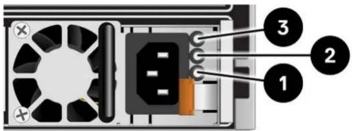
Table 3 DPE power supply LEDs
| LED Location State Description | |||
| AC power (input) Green AC power is on. | |||
| Off AC power is off. Verify source power | |||
| DC power (output) Green DC power is on. | |||
| Off DC power is off. Verify source power. | |||
| Fault Solid amber Power supply and backup fault. | Check cable connection. | ||
| Blinking amber | BIOS, POST, and OS starting up or system overheating. | ||
| Off No fault. | |||
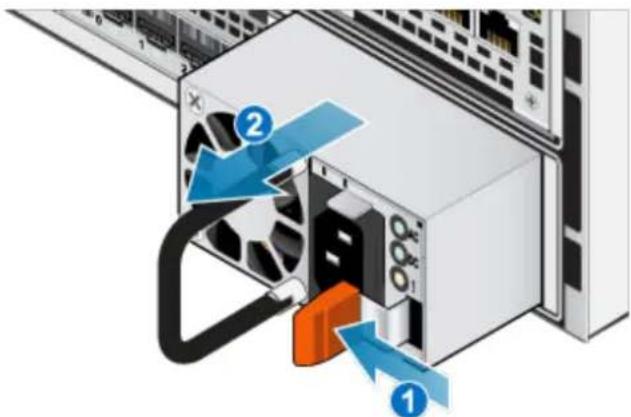
Remove a power supply
There are two power supplies. The power supplies are installed in the top and bottom SP assembly, and the top power supply is installed upside-down. This procedure works for removing either power supply, however, the direction in which the release handle
is pressed is to the left for the bottom power supply, and to the right for the top power supply.
Note
You do not need to power down the system to remove a power supply.
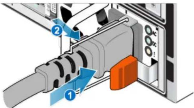
Procedure
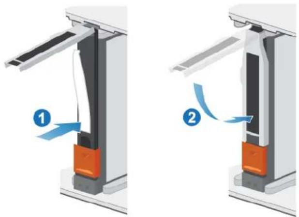
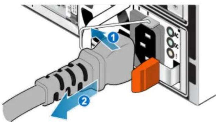
- Rotate the power cable retention bail to the left (to the right for the bottom power supply). Remove the power cable from the power supply.
Figure 32 Removing the power cable
- Push and hold the orange release tab to the left (to the right for the bottom power supply) and grasp the power supply by its handle. Remove the power supply by pulling it from the SP assembly.
Figure 33 Removing a power supply
Install a power supply
The power supplies are installed in the top and bottom SP assemblies, meaning that the top power supply is installed upside-down. This procedure works for installing either power supply.
Procedure
-
Align the power supply with the slot in the SP assembly. The power cable retention bail will be on the right for the bottom power supply and on the left for the top power supply.
-
Push the power supply into the SP assembly until it clicks into place.
Figure 34 Installing a power supply
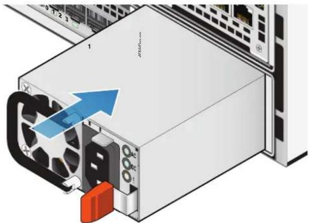
- Connect the power cable to the power supply and secure the cord with the retention bail at the connector.
Figure 35 Inserting the power cable
Verifying the operation of the new part in Unisphere
Verify that the new part is recognized by your system, and operating correctly. Procedure
- In Unisphere, select System View.
- On the Summary page, confirm that the system status is OK.
- Select the Enclosures page.
- Verify that the part appears with the OK status in the enclosure view. You may need to refresh Unisphere by clicking on the refresh icon next to the Enclosures view.
If the system health monitor shows the part as faulted, contact your service provider.
Returning a faulted part
We appreciate the return of defective material within 5 business days (for US returns). For International customers, please return defective material within 5-10
business days. All instructions and material required to return your defective part were supplied with your good part shipment.
Procedure
- Package the faulted part in the shipping box that contained the replacement part, and seal the box.
- Ship the failed part to your service provider as described in the instructions that were included with the replacement part.
- (Optional) For more information about returning customer-replaceable parts, from Unisphere, click Support > Replace Disk Drives, Power Supplies, and Other Parts > Return a Part to display the part return instructions.
If your screen does not show the Return a Part option, contact your service provider for instructions on what to do next.
Replace an embedded module
Take the following actions to remove the faulted embedded module and install the replacement embedded module into the system.
Identifying and locating the faulted part in Unisphere
Before you replace a faulted part, locate its placement within the storage system.
Procedure
- In Unisphere, select System View.
- Select the Enclosures page.
- Locate the faulted part marked orange, and displayed in the Enclosures view.
Preparing the SP assembly for service
Reset and hold is a special state during which power is maintained to the SP assembly so that I/O modules, embedded modules, and 4-port cards can be safely removed. This state has fewer management capabilities than Service Mode, but allows for easier I/O module, embedded module and 4-port card replacement.
Note
Both SP assemblies must NOT be in reset and hold simultaneously. The system should be up for at least 40 minutes since its last reboot before being placed into reset and hold.
Procedure
- Open Unisphere and select Service, then Service Tasks.
- Under the name of the SP assembly where you will install the new I/O module, embedded module or 4-port card, select Reset and Hold and then click Execute.
- When prompted, type the service password to put the SP assembly into reset and hold.
- (Optional) Either refresh the browser or follow the onscreen instructions to restore full-functionality to Unisphere.
When placing the primary storage processor into hold in reset, Unisphere becomes momentarily unresponsive as the management services transfer over
to the other SP. After about 10 minutes, the SP assembly's status will change to Degraded, and indicate that the SP assembly has been placed in held in reset. The SP assembly's status can be confirmed by checking the log entries in Unisphere under Events > Alerts.
- Wait until the SP assembly fault LED and power indicator LED are lit solid amber and green, respectively, and the peer SP assembly's Unsafe to Remove LED is lit before moving to the next task.
Embedded module LEDs
Use the fault LEDs to identify the faulted part.
Figure 36 Embedded module LEDs
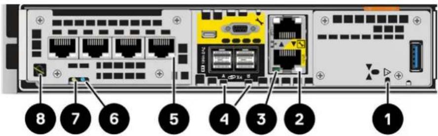
Table 4 Embedded module LEDs
| LED Location State Description | |||
| Embedded module power Amber embedded module has faulted | |||
| Off No fault has occurred, normal operation. | |||
| Ethernet port link Green Link established. | |||
| Off No link established. | |||
| Ethernet port activity Amber Port activity. | |||
| Off No port activity. | |||
| SAS port/activity Link Blue SAS port link is up. | |||
| Off No link established. | |||
| Port link Green Link up with high speed. | |||
| Amber Link up with degraded speed. | |||
| Off Link down. | |||
| Storage processor assembly fault | 6 | Amber Fault has occurred. | |
| Blue Storage processor assembly in Degraded Mode. | |||
| Amber or blue blinking | System is booting. | ||
| Blue and amber alternating (green for 3 seconds) | System not initialized. A management IP address has not been assigned. | ||
| Blue and amber alternating at one second intervals | Storage processor assembly in Service Mode. | ||
| Off No fault has occurred, normal operation. | |||
| Storage processor assembly power | 7 | Green Storage | processor assembly is on (main power). |
| Green blinking | Storage processor assembly is initializing a serial over LAN session (Standby Mode). | ||
| Off Storage processor assembly is off. | |||
| Unsafe to remove White Do not remove the embedded module. Improper removal could cause data loss. | |||
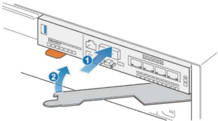
Remove a faulted embedded module
Procedure
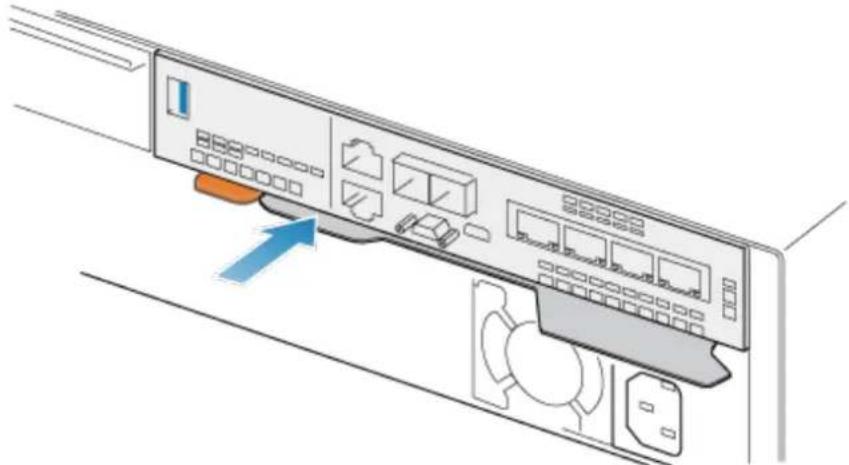
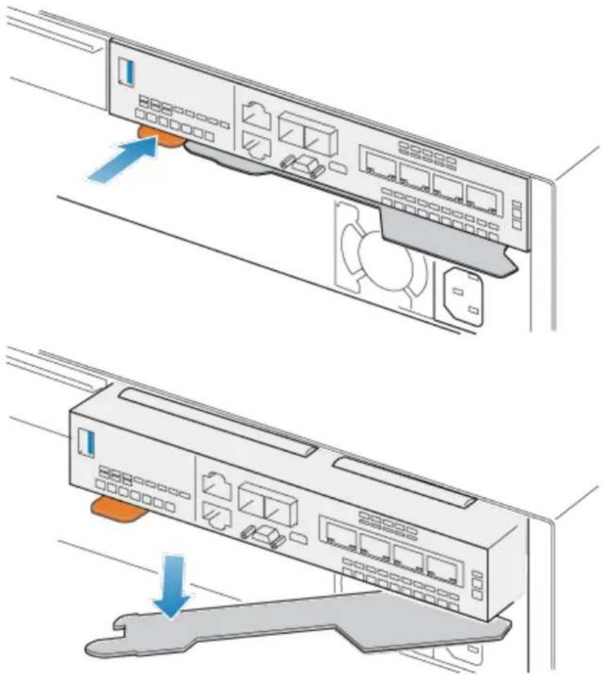
- Label and disconnect all cables attached to the embedded module.
- Push the orange tab to release the lever.
Figure 37 Releasing the lever on the embedded module
natural_image
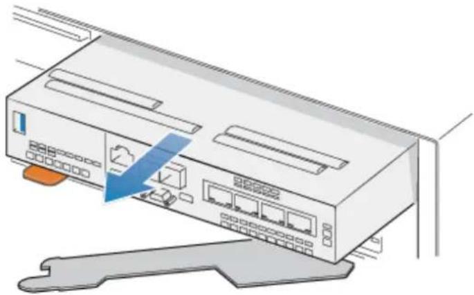
Illustration of a server rack with ports and ventilation slots, showing two configurations (no text or symbols)- Pull the release lever away from the system. The embedded module releases from the system as you pull the lever.
Figure 38 Removing the embedded module from the system

natural_image
Illustration of a network switch device with ports and a blue arrow indicating a location or connection point (no text or symbols present)- Remove the embedded module from the slot.
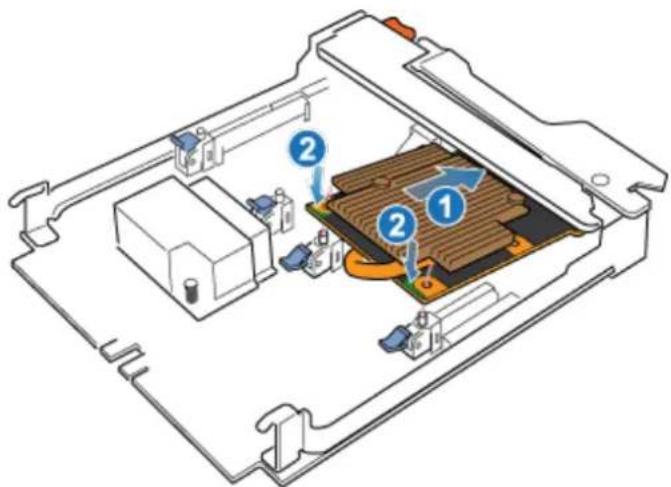
Transfer the 4-port card
If you are replacing the embedded module, remove the 4-port card from the old embedded module and install it into the new embedded module. Do not transfer the 4-port card while replacing a SP assembly.
Remove a 4-port card
Procedure
- Remove the SFPs from the front of the embedded module.
- Remove the air dam at the front of the embedded module by loosening the four captive screws.
- Push down the two blue tabs on the back of the 4-port card to release the 4-port card.
Figure 39 Opening the retaining tabs
natural_image
Technical line drawing of an electronic device casing with internal components and mounting brackets (no text or symbols)- Lift the 4-port card off the pegs, and pull the 4-port card away from the embedded module.
Figure 40 Removing the 4-port card
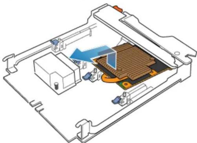
natural_image
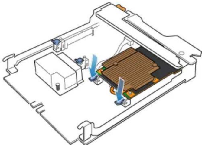
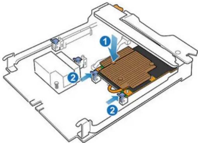
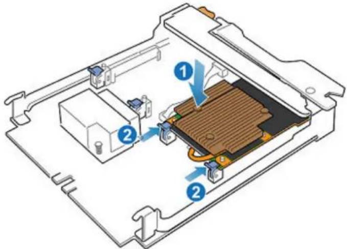
Isometric technical diagram of a device casing with internal components and a blue arrow indicating flow or movement (no text or symbols)Install a 4-port card
Procedure
-
Align the 4-port card in the embedded module so that the ports on the front line up with the slots on the front of the embedded module.
-
Align the white pegs beneath the holes on the 4-port card.

Do not force the 4-port card into place. If the 4-port card does not smoothly seat, re-align the pegs and try again.
Figure 41 Seating the 4-port card
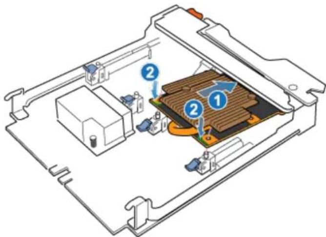
-
Gently push down on the upper-left circle on the 4-port card.
-
Push up on the blue tabs until they lock into place.
Figure 42 Locking the 4-port card into position
-
Replace the air dam and tighten the four captive screws.
-
Install the SFPs into the embedded module.
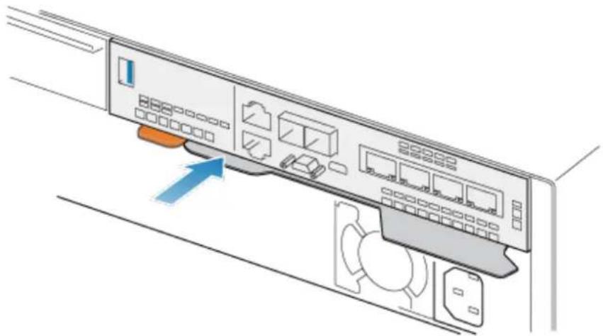
Install an embedded module
Procedure
- Align the embedded module with the empty slot and carefully push it into the slot.
As the embedded module is installed, the release lever rotates inward.
Figure 43 Installing the embedded module

- When the embedded module is fully seated, push the release lever back into the system until the orange tab locks the lever in place.
Figure 44 Locking the release lever
natural_image
Diagram of a server rack with ports and indicators, showing an arrow pointing to a specific area (no text or symbols present)- Connect each cable into the same port from which it was removed.
Rebooting a SP assembly into Normal Mode
Before you begin
Ensure that the replacement I/O module, embedded module, or 4-port card has been correctly installed using Unisphere. The replaced part's status indicates that the module is powered off and will power on during the next system reboot.
Reboot the recently serviced SP assembly into Normal Mode using the procedure that follows:
Procedure
- Open Unisphere and select Service, then Service Tasks.
- Under the name of the storage processor where you installed the new I/O module, embedded module, or 4-port card, select Reboot and click Execute.
- When prompted, type the Service Password to put the SP assembly into Normal Mode.
It may take up to 15 minutes for the system to complete its reboot to return to normal mode.
Verifying the operation of the new part in Unisphere
Verify that the new part is recognized by your system, and operating correctly.
Procedure
- In Unisphere, select System View.
- On the Summary page, confirm that the system status is OK.
- Select the Enclosures page.
- Verify that the part appears with the OK status in the enclosure view. You may need to refresh Unisphere by clicking on the refresh icon next to the Enclosures view.
If the system health monitor shows the part as faulted, contact your service provider.
Add a 4-port card
Take the following actions to install a new 4-port card into the system.
Preparing the SP assembly for service
Reset and hold is a special state during which power is maintained to the SP assembly so that I/O modules, embedded modules, and 4-port cards can be safely removed. This state has fewer management capabilities than Service Mode, but allows for easier I/O module, embedded module and 4-port card replacement.
Note
Both SP assemblies must NOT be in reset and hold simultaneously. The system should be up for at least 40 minutes since its last reboot before being placed into reset and hold.
Procedure
- Open Unisphere and select Service, then Service Tasks.
- Under the name of the SP assembly where you will install the new I/O module, embedded module or 4-port card, select Reset and Hold and then click Execute.
- When prompted, type the service password to put the SP assembly into reset and hold.
- (Optional) Either refresh the browser or follow the onscreen instructions to restore full-functionality to Unisphere.
When placing the primary storage processor into hold in reset, Unisphere becomes momentarily unresponsive as the management services transfer over to the other SP. After about 10 minutes, the SP assembly's status will change to Degraded, and indicate that the SP assembly has been placed in held in reset. The SP assembly's status can be confirmed by checking the log entries in Unisphere under Events >Alerts.
- Wait until the SP assembly fault LED and power indicator LED are lit solid amber and green, respectively, and the peer SP assembly's Unsafe to Remove LED is lit before moving to the next task.
Remove an embedded module
Procedure
-
Label and disconnect all cables attached to the embedded module.
-
Push the orange tab to release the lever.
Figure 45 Releasing the lever on the embedded module
natural_image
Illustration of a server rack with ports and ventilation slots, showing two configurations (no text or symbols)- Pull the release lever away from the system. The embedded module releases from the system as you pull the lever.
Figure 46 Removing the embedded module from the system
natural_image
Illustration of a network switch device with ports and a blue arrow pointing to the internal components (no text or symbols present)- Remove the embedded module from the slot.
Identify the location for the new 4-port card
Ensure that you install the new 4-port card in the correct location.
Install the new 4-port card in slot 0 within the embedded module. When looking at the embedded module from the front, slot 0 is on the left side of the embedded module.
Install a 4-port card
Procedure
- Remove the air dam at the front of the embedded module.
- Align the 4-port card in the embedded module so that the ports on the front line up with the slots on the front of the embedded module.
- Align the white pegs beneath the holes on the 4-port card.
CAUTION
Do not force the 4-port card into place. If the 4-port card does not smoothly seat, re-align the pegs and try again.
Figure 47 Seating the 4-port card
-
Gently push down on the upper-left circle on the 4-port card.
-
Push up on the blue tabs until they lock into place.
Figure 48 Locking the 4-port card into position
-
Install the air dam that came with the 4-port card, and tighten the four captive screws.
-
If the 4-port card includes SFPs, install them into the embedded module.
Install an embedded module
Procedure
- Align the embedded module with the empty slot and carefully push it into the slot.
As the embedded module is installed, the release lever rotates inward.
Figure 49 Installing the embedded module
- When the embedded module is fully seated, push the release lever back into the system until the orange tab locks the lever in place.
Figure 50 Locking the release lever
natural_image
Illustration of a server rack with ports and a blue arrow pointing to a specific component (no text or symbols present)- Connect each cable into the same port from which it was removed.
Adding the 4-port card to SP B
You have completed the addition of the 4-port card to SP A. Now you are ready to add the other 4-port card to SP B by repeating the tasks that you just performed for SP A.
Note
Ensure that you install the 4-port card in the same slot on SP B that was used on SP A.
Procedure
- Place SP B into reset and hold.
- Locate the slot for the new 4-port card on SP B.
- Remove the embedded module.
- Install the new 4-port card.
- Replace the embedded module.
- Reboot SP B into normal mode.
Rebooting a SP assembly into Normal Mode
Before you begin
Ensure that the replacement I/O module, embedded module, or 4-port card has been correctly installed using Unisphere. The replaced part's status indicates that the module is powered off and will power on during the next system reboot.
Reboot the recently serviced SP assembly into Normal Mode using the procedure that follows:
Procedure
- Open Unisphere and select Service, then Service Tasks.
- Under the name of the storage processor where you installed the new I/O module, embedded module, or 4-port card, select Reboot and click Execute.
- When prompted, type the Service Password to put the SP assembly into Normal Mode.
It may take up to 15 minutes for the system to complete its reboot to return to normal mode.
Committing the new I/O ports
You must commit the new I/O ports before they can be used.
Procedure
- In Unisphere, select System View.
- Select the DPE and select Commit IO Ports.
Note
Committing I/O ports requires multiple reboots of the SPs and may take up to an hour to complete. You can find I/O ports commit and SP reboot status details on Service > Logs. During these reboots you will temporarily lose Unisphere connectivity.
After this process completes, the new I/O ports have been successfully committed into the system.
If the commit of the new I/O ports fails, please wait 15 minutes for the system to fully boot and then re-attempt the commit process.
Verifying the operation of the new part in Unisphere
Verify that the new part is recognized by your system, and operating correctly.
Procedure
- In Unisphere, select System View.
- On the Summary page, confirm that the system status is OK.
- Select the Enclosures page.
- Verify that the part appears with the OK status in the enclosure view. You may need to refresh Unisphere by clicking on the refresh icon next to the Enclosures view.
If the system health monitor shows the part as faulted, contact your service provider.
Replace a 4-port card
Take the following actions to remove the 4-port card and install the replacement 4-port card into the system.
Identifying and locating the faulted part in Unisphere
Before you replace a faulted part, locate its placement within the storage system.
Procedure
- In Unisphere, select System View.
- Select the Enclosures page.
- Locate the faulted part marked orange, and displayed in the Enclosures view.
Preparing the SP assembly for service
Reset and hold is a special state during which power is maintained to the SP assembly so that I/O modules, embedded modules, and 4-port cards can be safely removed. This state has fewer management capabilities than Service Mode, but allows for easier I/O module, embedded module and 4-port card replacement.
Note
Both SP assemblies must NOT be in reset and hold simultaneously. The system should be up for at least 40 minutes since its last reboot before being placed into reset and hold.
Procedure
- Open Unisphere and select Service, then Service Tasks.
- Under the name of the SP assembly where you will install the new I/O module, embedded module or 4-port card, select Reset and Hold and then click Execute.
-
When prompted, type the service password to put the SP assembly into reset and hold.
-
(Optional) Either refresh the browser or follow the onscreen instructions to restore full-functionality to Unisphere.
When placing the primary storage processor into hold in reset, Unisphere becomes momentarily unresponsive as the management services transfer over to the other SP. After about 10 minutes, the SP assembly's status will change to Degraded, and indicate that the SP assembly has been placed in held in reset. The SP assembly's status can be confirmed by checking the log entries in Unisphere under Events > Alerts.
- Wait until the SP assembly fault LED and power indicator LED are lit solid amber and green, respectively, and the peer SP assembly's Unsafe to Remove LED is lit before moving to the next task.
Embedded module LEDs
Use the fault LEDs to identify the faulted part.
Figure 51 Embedded module LEDs
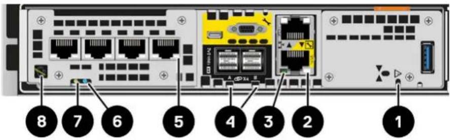
Table 5 Embedded module LEDs
| LED Location State Description | |||
| Embedded module power Amber embedded module has faulted | |||
| Off No fault has occurred, normal operation. | |||
| Ethernet port link Green Link established. | |||
| Off No link established. | |||
| Ethernet port activity Amber Port activity. | |||
| Off No port activity. | |||
| SAS port/activity Link Blue SAS port link is up. | |||
| Off No link established. | |||
| Port link Green Link up with high speed. | |||
| Amber Link up with degraded speed. | |||
| Off Link down. | |||
| Storage processor assembly fault | 6 | Amber Fault has occurred. | |
| Blue Storage processor assembly in Degraded Mode. | |||
| Amber or blue blinking | System is booting. | ||
| Blue and amber alternating (green for 3 seconds) | System not initialized. A management IP address has not been assigned. | ||
| Blue and amber alternating at one second intervals | Storage processor assembly in Service Mode. | ||
| Off No fault has occurred, normal operation. | |||
| Storage processor assembly power | 7 | Green Storage processor assembly is on (main power). | |
| Green blinking Storage processor assembly is initializing a serial over LAN session (Standby Mode). | |||
| Off Storage processor assembly is off. | |||
| Unsafe to remove White Do not remove the embedded module. Improper removal could cause data loss. | |||
| Off Safe to remove the embedded module when the embedded module has been properly prepared. | |||
Remove an embedded module
Procedure
- Label and disconnect all cables attached to the embedded module.
- Push the orange tab to release the lever.
Figure 52 Releasing the lever on the embedded module
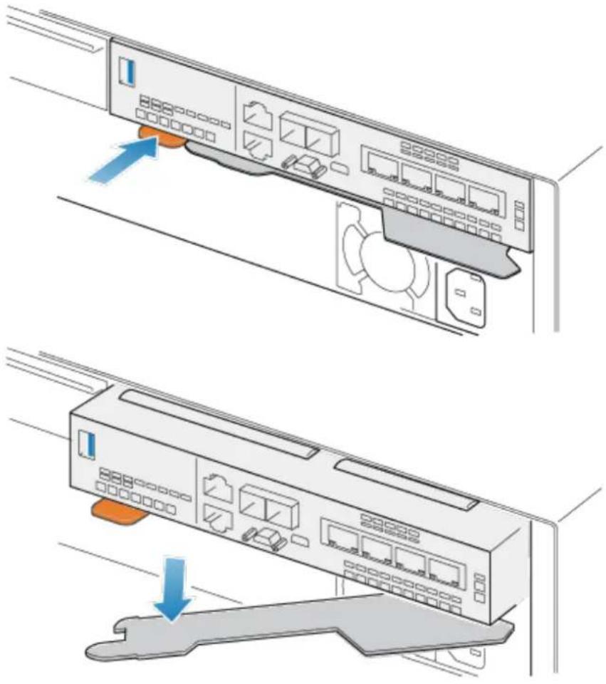
natural_image
Illustration of a network device showing two components: one with ports and one with a cable, both without any text or symbols.- Pull the release lever away from the system. The embedded module releases from the system as you pull the lever.
Figure 53 Removing the embedded module from the system

natural_image
Illustration of a network device with ports and a blue arrow pointing to a component (no text or symbols)- Remove the embedded module from the slot.
Remove a 4-port card
Procedure
- Remove the SFPs from the front of the embedded module.
- Remove the air dam at the front of the embedded module by loosening the four captive screws.
- Push down the two blue tabs on the back of the 4-port card to release the 4-port card.
Figure 54 Opening the retaining tabs

natural_image
Technical diagram of an electronic device showing internal components and wiring (no text or labels)- Lift the 4-port card off the pegs, and pull the 4-port card away from the embedded module.
Figure 55 Removing the 4-port card

natural_image
Technical diagram of an electronic device showing internal components and a blue arrow indicating flow or movement (no text or symbols present)Install a 4-port card
Procedure
- Align the 4-port card in the embedded module so that the ports on the front line up with the slots on the front of the embedded module.
- Align the white pegs beneath the holes on the 4-port card.
CAUTION
Do not force the 4-port card into place. If the 4-port card does not smoothly seat, re-align the pegs and try again.
Figure 56 Seating the 4-port card

- Gently push down on the upper-left circle on the 4-port card.
- Push up on the blue tabs until they lock into place.
Figure 57 Locking the 4-port card into position
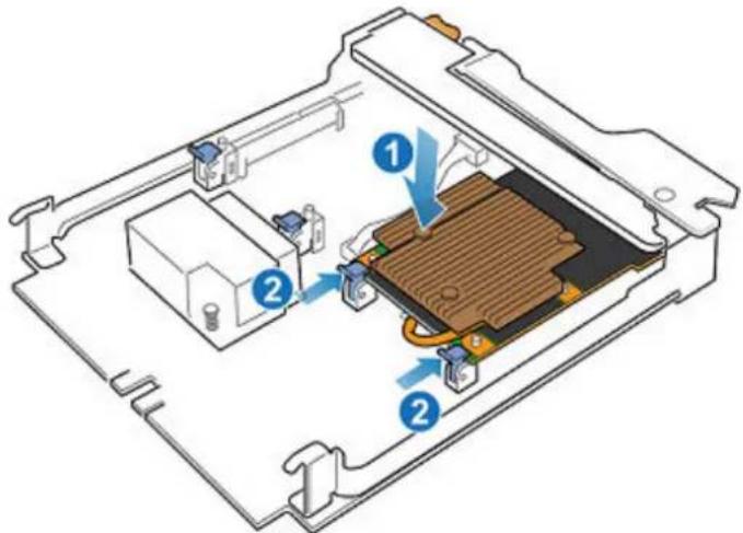
- Replace the air dam and tighten the four captive screws.
- Install the SFPs into the embedded module.
Install an embedded module
Procedure
- Align the embedded module with the empty slot and carefully push it into the slot.
As the embedded module is installed, the release lever rotates inward.
Figure 58 Installing the embedded module

- When the embedded module is fully seated, push the release lever back into the system until the orange tab locks the lever in place.
Figure 59 Locking the release lever

natural_image
Illustration of a server rack with ports and a blue arrow pointing to a component (no text or symbols present)- Connect each cable into the same port from which it was removed.
Rebooting a SP assembly into Normal Mode
Before you begin
Ensure that the replacement I/O module, embedded module, or 4-port card has been correctly installed using Unisphere. The replaced part's status indicates that the module is powered off and will power on during the next system reboot.
Reboot the recently serviced SP assembly into Normal Mode using the procedure that follows:
Procedure
- Open Unisphere and select Service, then Service Tasks.
- Under the name of the storage processor where you installed the new I/O module, embedded module, or 4-port card, select Reboot and click Execute.
- When prompted, type the Service Password to put the SP assembly into Normal Mode.
It may take up to 15 minutes for the system to complete its reboot to return to normal mode.
Verifying the operation of the new part in Unisphere
Verify that the new part is recognized by your system, and operating correctly.
Procedure
- In Unisphere, select System View.
- On the Summary page, confirm that the system status is OK.
- Select the Enclosures page.
- Verify that the part appears with the OK status in the enclosure view. You may need to refresh Unisphere by clicking on the refresh icon next to the Enclosures view.
If the system health monitor shows the part as faulted, contact your service provider.
Add an SFP
Take the following actions to add a new SFP into the system.
Install an SFP module
Procedure
- Verify that the replacement SFP module has the same part number as the failed SFP module.
The part number is on a label attached to the SFP module. - Push the spring release latch up and slide the new SFP module into the port until it is securely connected.
Figure 60 Installing an SFP module
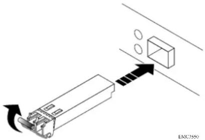
-
Push the spring release down to lock the SFP module into place.
-
Reconnect the cable to the replacement SFP module.
Committing the new I/O ports
You must commit the new I/O ports before they can be used.
Procedure
- In Unisphere, select System View.
- Select the DPE and select Commit IO Ports.
Note
Committing I/O ports requires multiple reboots of the SPs and may take up to an hour to complete. You can find I/O ports commit and SP reboot status details on Service > Logs. During these reboots you will temporarily lose Unisphere connectivity.
After this process completes, the new I/O ports have been successfully committed into the system.
If the commit of the new I/O ports fails, please wait 15 minutes for the system to fully boot and then re-attempt the commit process.
Verifying the operation of the new part in Unisphere
Verify that the new part is recognized by your system, and operating correctly.
Procedure
- In Unisphere, select System View.
- On the Summary page, confirm that the system status is OK.
- Select the Enclosures page.
- Verify that the part appears with the OK status in the enclosure view. You may need to refresh Unisphere by clicking on the refresh icon next to the Enclosures view.
If the system health monitor shows the part as faulted, contact your service provider.
Replace a faulted SFP
Take the following actions to remove the faulted SFP and install the replacement SFP into the system.
Identifying and locating the faulted part in Unisphere
Before you replace a faulted part, locate its placement within the storage system.
Procedure
- In Unisphere, select System View.
- Select the Enclosures page.
- Locate the faulted part marked orange, and displayed in the Enclosures view.
Remove an SFP module
Procedure
- If a cable is connected to the SFP, disconnect the cable.
- Gently pull down on the spring release latch.
- While still holding onto the latch, gently pull out the SFP module.

Do not remove the I/O module. Removing the I/O module causes the SP assembly to reboot immediately.
Figure 61 Removing an SFP module
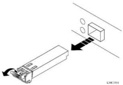
Install an SFP module
Procedure
- Verify that the replacement SFP module has the same part number as the failed SFP module.
The part number is on a label attached to the SFP module.
- Push the spring release latch up and slide the new SFP module into the port until it is securely connected.
Figure 62 Installing an SFP module
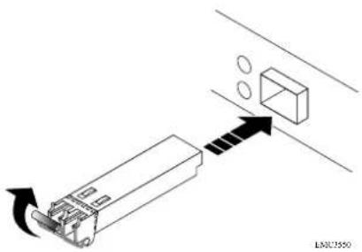
- Push the spring release down to lock the SFP module into place.
- Reconnect the cable to the replacement SFP module.
Verifying the operation of the new part in Unisphere
Verify that the new part is recognized by your system, and operating correctly.
Procedure
- In Unisphere, select System View.
- On the Summary page, confirm that the system status is OK.
- Select the Enclosures page.
- Verify that the part appears with the OK status in the enclosure view. You may need to refresh Unisphere by clicking on the refresh icon next to the Enclosures view.
If the system health monitor shows the part as faulted, contact your service provider.
Returning a faulted part
We appreciate the return of defective material within 5 business days (for US returns). For International customers, please return defective material within 5-10 business days. All instructions and material required to return your defective part were supplied with your good part shipment.
Procedure
- Package the faulted part in the shipping box that contained the replacement part, and seal the box.
- Ship the failed part to your service provider as described in the instructions that were included with the replacement part.
- (Optional) For more information about returning customer-replaceable parts, from Unisphere, click Support > Replace Disk Drives, Power Supplies, and Other Parts > Return a Part to display the part return instructions.
If your screen does not show the Return a Part option, contact your service provider for instructions on what to do next.
Replace an I/O module
Take the following actions to remove the faulted I/O module and install the replacement I/O module into the system.
Identifying and locating the faulted part in Unisphere
Before you replace a faulted part, locate its placement within the storage system.
Procedure
- In Unisphere, select System View.
- Select the Enclosures page.
- Locate the faulted part marked orange, and displayed in the Enclosures view.
Preparing the SP assembly for service
Reset and hold is a special state during which power is maintained to the SP assembly so that I/O modules, embedded modules, and 4-port cards can be safely removed. This state has fewer management capabilities than Service Mode, but allows for easier I/O module, embedded module and 4-port card replacement.
Note
Both SP assemblies must NOT be in reset and hold simultaneously. The system should be up for at least 40 minutes since its last reboot before being placed into reset and hold.
Procedure
- Open Unisphere and select Service, then Service Tasks.
- Under the name of the SP assembly where you will install the new I/O module, embedded module or 4-port card, select Reset and Hold and then click Execute.
-
When prompted, type the service password to put the SP assembly into reset and hold.
-
(Optional) Either refresh the browser or follow the onscreen instructions to restore full-functionality to Unisphere.
When placing the primary storage processor into hold in reset, Unisphere becomes momentarily unresponsive as the management services transfer over to the other SP. After about 10 minutes, the SP assembly's status will change to Degraded, and indicate that the SP assembly has been placed in held in reset. The SP assembly's status can be confirmed by checking the log entries in Unisphere under Events > Alerts.
- Wait until the SP assembly fault LED and power indicator LED are lit solid amber and green, respectively, and the peer SP assembly's Unsafe to Remove LED is lit before moving to the next task.
DPE I/O module LEDs
Use the fault LEDs to identify the faulted part.
Figure 63 DPE I/O module LEDs
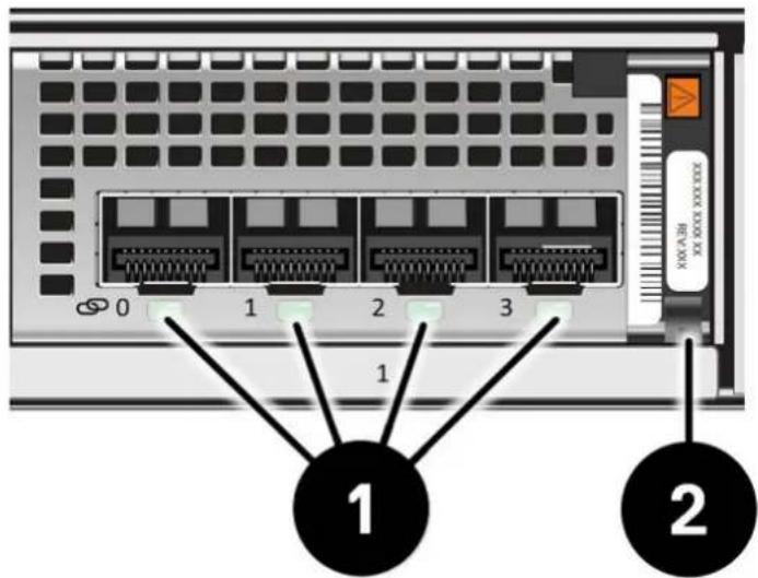
Table 6 DPE I/O module LEDs
| LED Location State Description | |||
| Port link Green or blue Link up | 1 | ||
| Off Link down | |||
| Power fault Green Power | 2 | ||
| Amber Power fault | |||
Remove a faulted I/O module
Procedure
- Pull the trigger mechanism on the I/O module handle to release it.
Figure 64 Releasing the I/O module
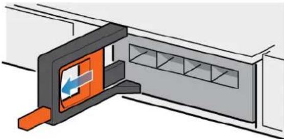
natural_image
Isometric illustration of a door with an orange panel and blue directional arrow, mounted on a wall (no text or symbols)- Gently pull the I/O module from the slot.
Figure 65 Removing the I/O module
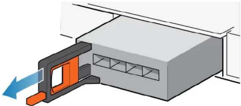
natural_image
3D diagram of a mechanical assembly with an orange component and blue directional arrow (no text or symbols)Install a new I/O module
Procedure
- Align the module with the empty slot and carefully push the module into the slot.
Figure 66 Installing an I/O module

natural_image
3D diagram of a mechanical assembly with an orange bracket and blue directional arrow (no text or symbols)-
When the I/O module appears seated, push and release the small button on the handle.
-
If the button remains in, the module is fully seated.
- If the button springs back, gently push the module further into the chassis, then push it again.
- If the button still does not rest flush with its handle, remove the module and repeat steps 1 and 2.
Figure 67 Locking in the I/O module
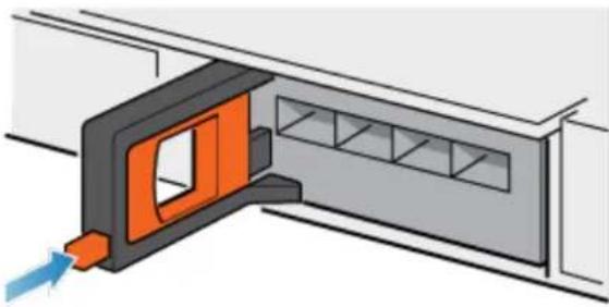
natural_image
Diagram of a door opening with orange and gray components, showing airflow direction (no text or symbols)- Connect the cables into the assigned I/O module ports.
Rebooting a SP assembly into Normal Mode
Before you begin
Ensure that the replacement I/O module, embedded module, or 4-port card has been correctly installed using Unisphere. The replaced part's status indicates that the module is powered off and will power on during the next system reboot.
Reboot the recently serviced SP assembly into Normal Mode using the procedure that follows:
Procedure
- Open Unisphere and select Service, then Service Tasks.
-
Under the name of the storage processor where you installed the new I/O module, embedded module, or 4-port card, select Reboot and click Execute.
-
When prompted, type the Service Password to put the SP assembly into Normal Mode.
It may take up to 15 minutes for the system to complete its reboot to return to normal mode.
Verifying the operation of the new part in Unisphere
Verify that the new part is recognized by your system, and operating correctly.
Procedure
- In Unisphere, select System View.
- On the Summary page, confirm that the system status is OK.
- Select the Enclosures page.
- Verify that the part appears with the OK status in the enclosure view. You may need to refresh Unisphere by clicking on the refresh icon next to the Enclosures view.
If the system health monitor shows the part as faulted, contact your service provider.
Returning a faulted part
We appreciate the return of defective material within 5 business days (for US returns). For International customers, please return defective material within 5-10 business days. All instructions and material required to return your defective part were supplied with your good part shipment.
Procedure
- Package the faulted part in the shipping box that contained the replacement part, and seal the box.
- Ship the failed part to your service provider as described in the instructions that were included with the replacement part.
- (Optional) For more information about returning customer-replaceable parts, from Unisphere, click Support > Replace Disk Drives, Power Supplies, and Other Parts > Return a Part to display the part return instructions.
If your screen does not show the Return a Part option, contact your service provider for instructions on what to do next.
Add an I/O module
Take the following actions to install a new I/O module into the system.
If you are adding a 4-port SAS I/O module and connecting an 80-drive DAE that requires x8 connectivity, insert the SAS cable into the 4-port SAS I/O module before persisting the I/O module. The 4-port SAS I/O module must be persisted with the cable inserted for x8 connectivity.
Note
If the SAS back-end I/O module is powered on without any cables inserted, it is automatically set at x4 and cannot be used for x8 lane cabling.
Locating a slot for a new I/O module
Locate the slot with the I/O filler module that you want to replace with the new I/O module.
Remove a filler I/O module
Procedure
- Pull the trigger mechanism on the filler I/O module handle to release it.
- Gently pull the filler module from the slot.
Install a new I/O module
Procedure
- Align the module with the empty slot and carefully push the module into the slot.
Figure 68 Installing an I/O module
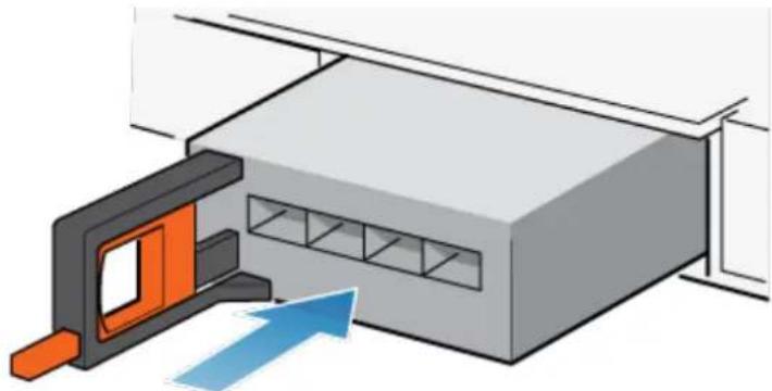
natural_image
3D diagram of a mechanical assembly with an orange bracket and blue directional arrow (no text or symbols)-
When the I/O module appears seated, push and release the small button on the handle.
-
If the button remains in, the module is fully seated.
- If the button springs back, gently push the module further into the chassis, then push it again.
- If the button still does not rest flush with its handle, remove the module and repeat steps 1 and 2.
Figure 69 Locking in the I/O module
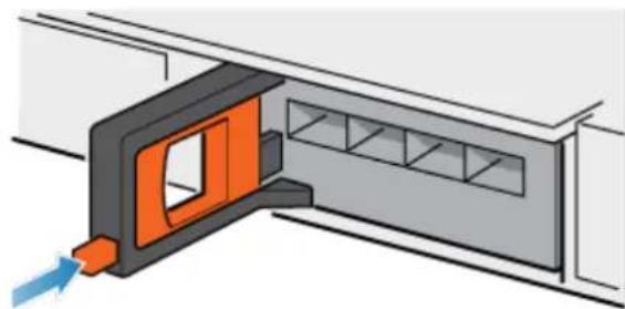
natural_image
Diagram of a door opening with orange and gray components, showing internal structure (no text or symbols)- Connect the cables into the assigned I/O module ports.
Verifying that the new I/O ports are recognized
Verify that the new I/O ports are recognized by your system and is not faulted using the procedure that follows.
NOTICE
Do not attempt to commit the new I/O ports at this time. Wait until directed later in this procedure for the appropriate point to commit both new I/O ports.
Procedure
- Open Unisphere ^TM and select System View.
- Select the new I/O ports in the the graphical view:
In the graphical view, the ports should be highlighted yellow.
If the system health monitor shows the ports as faulted, contact your service provider.
Adding the I/O module to SP B
You have completed the addition of the I/O module to SP A. Now you are ready to add the other I/O module to SP B by repeating the following tasks that you just performed for SP A:
Note
Ensure that you install the I/O module in the same slot on SP B that was used on SP A.
- Locate the slot for the new I/O module.
- Remove the I/O filler module from the SP B assembly.
- Unpack the I/O module.
- Install the I/O module.
- Verify that the system recognizes the I/O module.
Committing the new I/O ports
You must commit the new I/O ports before they can be used.
Procedure
- In Unisphere, select System View.
- Select the DPE and select Commit IO Ports.
Note
Committing I/O ports requires multiple reboots of the SPs and may take up to an hour to complete. You can find I/O ports commit and SP reboot status details on Service > Logs. During these reboots you will temporarily lose Unisphere connectivity.
After this process completes, the new I/O ports have been successfully committed into the system.
If the commit of the new I/O ports fails, please wait 15 minutes for the system to fully boot and then re-attempt the commit process.
Take the following actions to remove the faulted fan module and install the replacement fan module into the system.
Identifying and locating the faulted part in Unisphere
Before you replace a faulted part, locate its placement within the storage system.
Procedure
- In Unisphere, select System View.
- Select the Enclosures page.
- Locate the faulted part marked orange, and displayed in the Enclosures view.
Preparing the storage processor (SP) for service
To protect your system from accidental data loss during this maintenance activity, prepare the SP for service. You prepare the SP for service by putting it in Service Mode.
Entering Service Mode stops I/O on the SP so that service tasks can be safely performed.
Note
Both SPs must NOT be in Service Mode at the same time.
Procedure
- Open Unisphere and select Service, then Service Tasks.
- Under the name of the storage processor where you will install the new part, select Enter Service Mode and then click Execute.
- When prompted, enter the Service Password to put the SP into Service Mode.
- (Optional) Either refresh your browser or follow the on-screen instructions to restore full-functionality to Unisphere.
When placing the primary storage processor into Service Mode, Unisphere will become momentarily unresponsive (about one minute) as the management services transfer over to the other SP. - Return to cabinet with the system and locate the SP in the DPE from the back of the cabinet.
- Wait until the SP fault LED is flashing alternating amber and blue before continuing to the next task.
The SP fault LED will flash alternating amber and blue while the SP remains in Service mode and is receiving active power.
Figure 70 Storage processor assembly LEDs

Table 7 Storage processor assembly LEDs
| LED Location State Description | |||
| Storage processor assembly fault | 1 | Amber Fault has occurred. | |
| Blue A management IP address has been assigned. | |||
| Amber or blue blinking | System is booting. | ||
| Blue and amber alternating (blue for 3 seconds) | System not initialized. A management IP address has not been assigned. | ||
| Blue and amber alternating at one second intervals | Storage processor assembly in Service Mode. | ||
| Off No fault has occurred, normal operation. | |||
| Storage processor assembly power | 2 | Green Storage | processor assembly is on (main power). |
| Green blinking | Storage processor assembly is initializing a serial over LAN session (Standby Mode). | ||
| Off Storage processor assembly is off. | |||
Remove the SP assembly
This procedure describes how to remove a SP assembly from the chassis. There are two SP assemblies. The top SP assembly is considered to be upside-down and mirrors the bottom SP assembly. The illustration shows the removal of the bottom SP assembly. The procedure for removing the top SP assembly is the same.
CAUTION
Do not remove a SP assembly while the "Unsafe to remove" LED is lit.
Procedure
- Rotate the power cable retention bail to the left (right for top power supply). Disconnect the power cable from the power supply.
Note
If the I/O module and network cables are not already labeled, label them clearly for reconnecting later.
Figure 71 Removing the power cable

- Disconnect the network and all other cables from the back of the I/O modules and network ports on the SP assembly.
Note
Do not remove any cables from the other SP assembly.
- Pull the orange release trigger while gently pushing in on the SP assembly.
The hook disengages from the locking mechanism, and the release tab slides out.
Note
The SP assembly comes completely out of the chassis. Be prepared to support the SP assembly to avoid dropping it.
Figure 72 Disengaging the locking mechanism
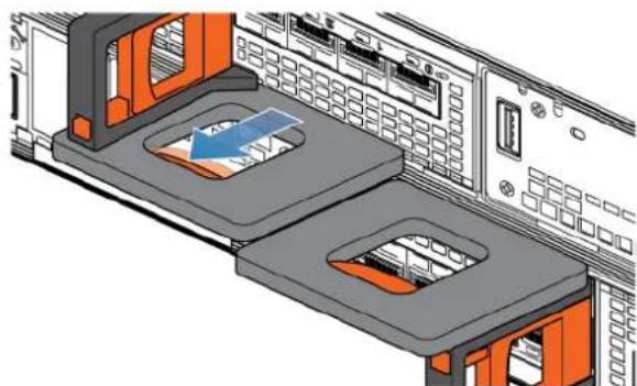
natural_image
3D technical illustration of a server rack with two orange panels and internal components (no text or symbols)- Use the release handle to pull the SP assembly outward enough to grasp the sides with both hands. Then, with both hands supporting the SP assembly, pull the SP assembly fully out of the enclosure.
Figure 73 Removing the SP assembly

natural_image
Diagram of a server rack with attached hardware components and a blue arrow indicating a loading or movement (no text or symbols present)- Place the SP assembly on a clean, flat, static-free work surface.
Remove the top cover from the SP assembly
Before you begin
Ensure that the internal battery has powered off before removing the top cover. After removing the SP assembly from the rack, wait at least 30 seconds, or until you hear the internal battery power off.
Procedure
- While pushing down the two blue release buttons, slide the top cover towards the rear of the system, until it stops.
Figure 74 Releasing the top cover
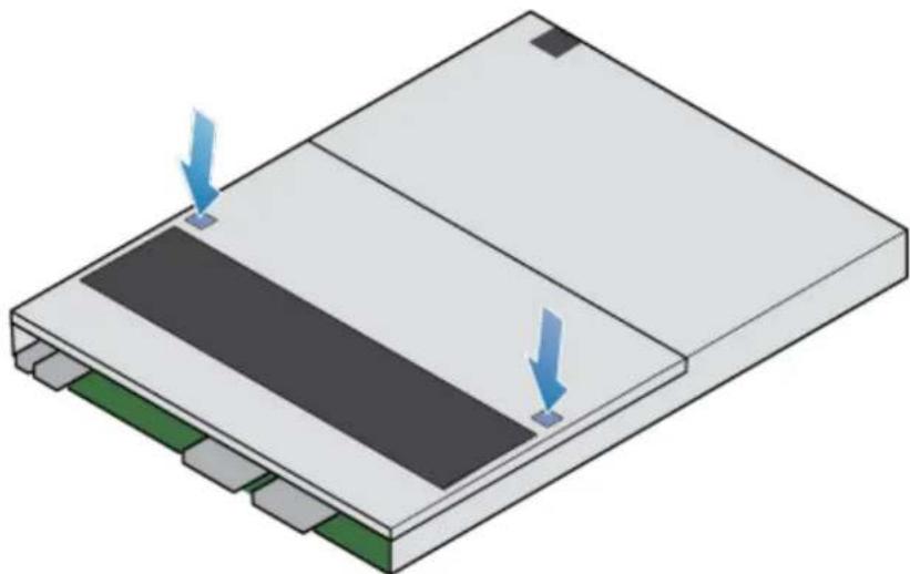
natural_image
Isometric view of a rectangular electronic device with two blue arrows pointing to its top panel (no text or symbols present)- Lift the top cover upward and remove it from the SP assembly.
Figure 75 Removing the top cover

natural_image
3D diagram of a device with a blue arrow pointing to a component, no text or symbols presentRemove the faulted fan module
Procedure
- Disconnect the fan module power cable from the motherboard.
Figure 76 Disconnecting fan power cable
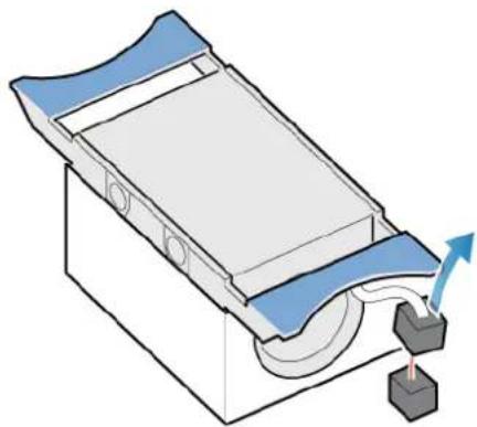
natural_image
Diagram of a mechanical device with a curved panel and directional arrows indicating motion (no text or symbols)- Unhook the fan module power cable from the cable holder.
- Squeeze the blue release tabs.
- Lift the fan module away from the motherboard.
Figure 77 Removing the fan from the motherboard
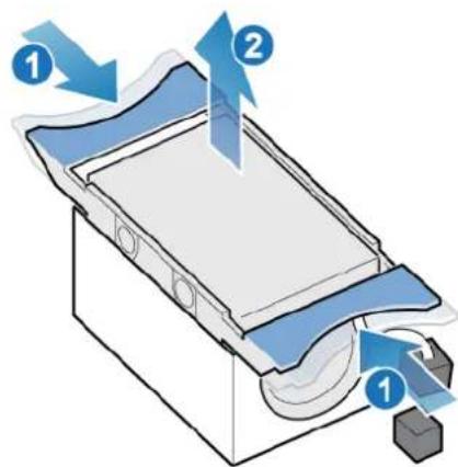
- Place the fan module into the mounting position in the SP assembly.
- Squeeze the blue tabs and press downward to lock the fan module into position.
- Connect the fan module power cable to the connector on the motherboard.
Figure 78 Installing the fan module
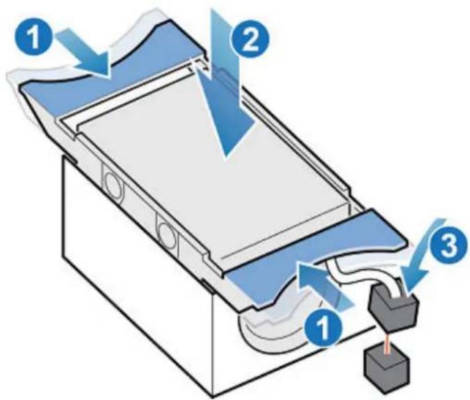
Install the top cover on the SP assembly
Procedure
- Position the top cover over the SP assembly and align it with the slots in the sides at the rear of the SP assembly.
Figure 79 Aligning the top cover
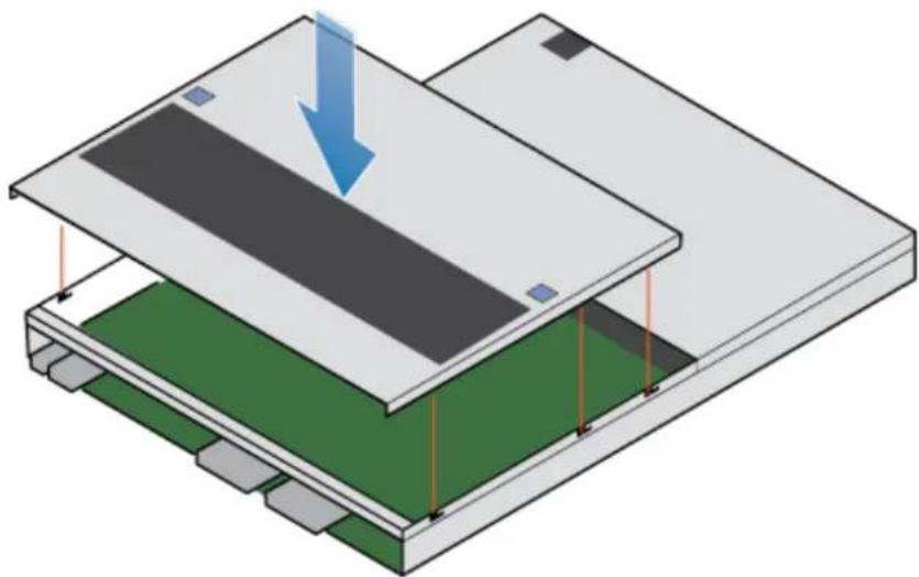
natural_image
Isometric diagram of a layered electronic device with a blue arrow indicating downward motion (no text or symbols)- Pull the top cover forward to secure it in place.
Figure 80 Securing the top cover

natural_image
Isometric view of a rectangular electronic device with a blue arrow pointing to its internal structure (no text or symbols)Install the SP assembly
Procedure
- Align the pins on the top of the SP assembly with the grooves on the top of the chassis.
- Slide the SP assembly into the chassis until it stops, about halfway in.
Figure 81 Sliding the SP assembly halfway into the chassis

natural_image
Diagram of a server rack with orange connectors and drive bays, showing internal components and connection points (no text or labels)- Pull the black release tab out completely, and slide the rest of the SP assembly back into the chassis.
The black release tab slides back into the system as it is inserted.
Figure 82 Installing the SP assembly

natural_image
Isometric view of a server rack with orange and black components, showing internal layout and ventilation slots (no text or labels)- Pull the orange release trigger and push in gently to re-engage the locking mechanism.
If the black release tab comes out when pulled, the locking mechanism is not engaged.
Rebooting an SP assembly into Normal Mode
Before you begin
If you removed the SP assembly during the replacement, wait about 10-15 minutes after reinserting the SP assembly into the system to allow the SP assembly to fully reboot into Service Mode. Ensure that the SP assembly fault LED is flashing alternating amber and blue (1 Hz) before continuing.
Note
If you attempt this task before the SP assembly has completed its automatic reboot into Service Mode, the attempt to reboot into Normal mode fails.
Reboot the recently serviced SP assembly into Normal Mode using the procedure that follows:
Procedure
- Open Unisphere and select Service, then Service Tasks.
- Under the name of the SP assembly where you installed the new part, select Reboot and the click Execute.
- When prompted, enter the service password to put the SP assembly into Normal Mode.
It may take up to 15 minutes for the system to complete its reboot, and return to normal mode.
Verifying the operation of the new part in Unisphere
Verify that the new part is recognized by your system, and operating correctly.
Procedure
- In Unisphere, select System View.
- On the Summary page, confirm that the system status is OK.
- Select the Enclosures page.
- Verify that the part appears with the OK status in the enclosure view. You may need to refresh Unisphere by clicking on the refresh icon next to the Enclosures view.
If the system health monitor shows the part as faulted, contact your service provider.
Returning a faulted part
We appreciate the return of defective material within 5 business days (for US returns). For International customers, please return defective material within 5-10 business days. All instructions and material required to return your defective part were supplied with your good part shipment.
Procedure
- Package the faulted part in the shipping box that contained the replacement part, and seal the box.
- Ship the failed part to your service provider as described in the instructions that were included with the replacement part.
- (Optional) For more information about returning customer-replaceable parts, from Unisphere, click Support > Replace Disk Drives, Power Supplies, and Other Parts > Return a Part to display the part return instructions.
If your screen does not show the Return a Part option, contact your service provider for instructions on what to do next.
Replace a dual inline memory module (DIMM)
Take the following actions to remove the faulted DIMM and install the replacement DIMM into the system.
The DIMMs are located within the SP assembly. You can access the DIMMs by removing the SP assembly from the chassis and opening the top cover.
Identifying and locating the faulted part in Unisphere
Before you replace a faulted part, locate its placement within the storage system.
Procedure
- In Unisphere, select System View.
- Select the Enclosures page.
- Locate the faulted part marked orange, and displayed in the Enclosures view.
Preparing the storage processor (SP) for service
To protect your system from accidental data loss during this maintenance activity, prepare the SP for service. You prepare the SP for service by putting it in Service Mode.
Entering Service Mode stops I/O on the SP so that service tasks can be safely performed.
Note
Both SPs must NOT be in Service Mode at the same time.
Procedure
- Open Unisphere and select Service, then Service Tasks.
- Under the name of the storage processor where you will install the new part, select Enter Service Mode and then click Execute.
- When prompted, enter the Service Password to put the SP into Service Mode.
- (Optional) Either refresh your browser or follow the on-screen instructions to restore full-functionality to Unisphere.
When placing the primary storage processor into Service Mode, Unisphere will become momentarily unresponsive (about one minute) as the management services transfer over to the other SP. - Return to cabinet with the system and locate the SP in the DPE from the back of the cabinet.
- Wait until the SP fault LED is flashing alternating amber and blue before continuing to the next task.
The SP fault LED will flash alternating amber and blue while the SP remains in Service mode and is receiving active power.
Figure 83 Storage processor assembly LEDs
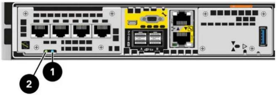
Table 8 Storage processor assembly LEDs
| LED Location State Description | |||
| Storage processor assembly fault | 1 | Amber Fault has occurred. | |
| Blue A management IP address has been assigned. | |||
| Amber or blue blinking | System is booting. | ||
| Blue and amber alternating (blue for 3 seconds) | System not initialized. A management IP address has not been assigned. | ||
| Blue and amber alternating at one second intervals | Storage processor assembly in Service Mode. | ||
| Off No fault has occurred, normal operation. | |||
| Storage processor assembly power | 2 | Green Storage | processor assembly is on (main power). |
| Green blinking | Storage processor assembly is initializing a serial over LAN session (Standby Mode). | ||
| Off Storage processor assembly is off. | |||
Remove the SP assembly
This procedure describes how to remove a SP assembly from the chassis. There are two SP assemblies. The top SP assembly is considered to be upside-down and mirrors the bottom SP assembly. The illustration shows the removal of the bottom SP assembly. The procedure for removing the top SP assembly is the same.
CAUTION
Do not remove a SP assembly while the "Unsafe to remove" LED is lit.
Procedure
- Rotate the power cable retention bail to the left (right for top power supply). Disconnect the power cable from the power supply.
Note
If the I/O module and network cables are not already labeled, label them clearly for reconnecting later.
Figure 84 Removing the power cable
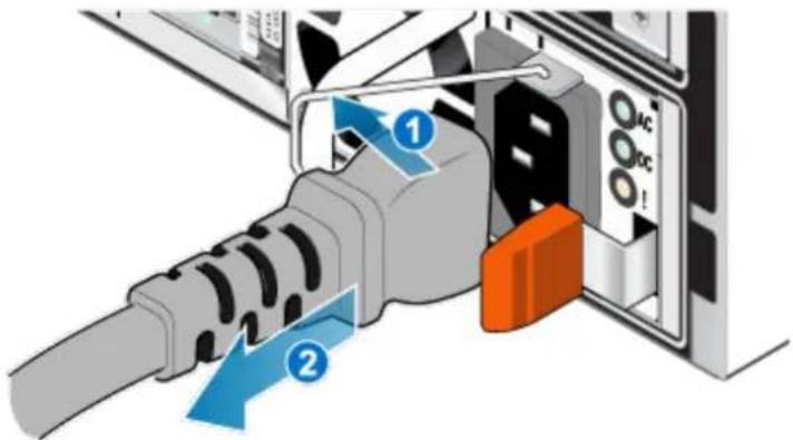
- Disconnect the network and all other cables from the back of the I/O modules and network ports on the SP assembly.
Note
Do not remove any cables from the other SP assembly.
- Pull the orange release trigger while gently pushing in on the SP assembly.
The hook disengages from the locking mechanism, and the release tab slides out.
Note
The SP assembly comes completely out of the chassis. Be prepared to support the SP assembly to avoid dropping it.
Figure 85 Disengaging the locking mechanism
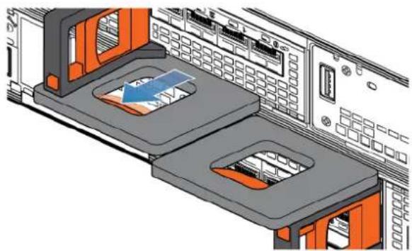
natural_image
3D technical illustration of a server rack with two orange storage compartments and internal components (no text or symbols)- Use the release handle to pull the SP assembly outward enough to grasp the sides with both hands. Then, with both hands supporting the SP assembly, pull the SP assembly fully out of the enclosure.
Figure 86 Removing the SP assembly
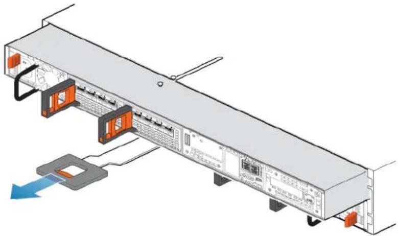
natural_image
Diagram of a server rack with connected ports and a highlighted CPU socket (no text or labels)- Place the SP assembly on a clean, flat, static-free work surface.
Remove the top cover from the SP assembly
Before you begin
Ensure that the internal battery has powered off before removing the top cover. After removing the SP assembly from the rack, wait at least 30 seconds, or until you hear the internal battery power off.
Procedure
- While pushing down the two blue release buttons, slide the top cover towards the rear of the system, until it stops.
Figure 87 Releasing the top cover

natural_image
Isometric view of a rectangular electronic device with two blue arrows pointing to its top panel (no text or symbols present)- Lift the top cover upward and remove it from the SP assembly.
Figure 88 Removing the top cover

natural_image
Isometric view of a rectangular electronic component with a blue arrow indicating upward motion (no text or symbols)Remove the faulted dual inline memory module
Procedure
- Locate the faulted DIMM in the SP assembly.
The DIMMs are identified by white or black retaining tabs.
-
Depress the white or black retaining tabs downward to free the DIMM from its slot.
-
Remove the faulted DIMM.
Figure 89 Removing the DIMM
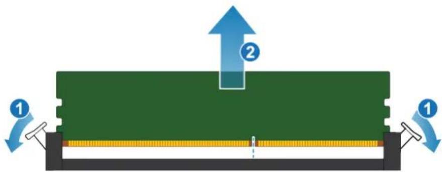
Install the dual inline memory module
Procedure
-
Touching only the outside edges of the DIMM, align the DIMM with the connector.
-
Firmly push the carrier straight down into the connector.
When the DIMM is fully seated, you will hear a snap, and feel the connector latches click into place.
Figure 90 Installing the DIMM
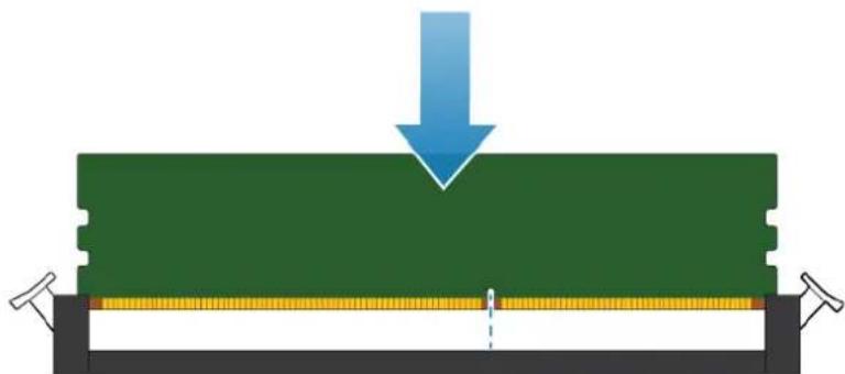
natural_image
Diagram showing a blue arrow pointing downward over a green rectangular block, with no text or symbols present.- Ensure that the tabs have locked into place and the DIMM is secure.
Install the top cover on the SP assembly
Procedure
- Position the top cover over the SP assembly and align it with the slots in the sides at the rear of the SP assembly.
Figure 91 Aligning the top cover
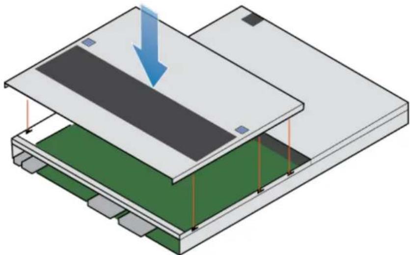
natural_image
Isometric diagram of a layered electronic device with a blue arrow indicating downward motion (no text or symbols)- Pull the top cover forward to secure it in place.
Figure 92 Securing the top cover

natural_image
Isometric view of a rectangular electronic device with a blue arrow pointing to its internal structure (no text or symbols)Install the SP assembly
Procedure
- Align the pins on the top of the SP assembly with the grooves on the top of the chassis.
- Slide the SP assembly into the chassis until it stops, about halfway in.
Figure 93 Sliding the SP assembly halfway into the chassis

natural_image
Diagram of a server rack with orange ports and connected cables, showing internal components and a blue arrow indicating a loading or connection point (no text or symbols present)- Pull the black release tab out completely, and slide the rest of the SP assembly back into the chassis.
The black release tab slides back into the system as it is inserted.
Figure 94 Installing the SP assembly
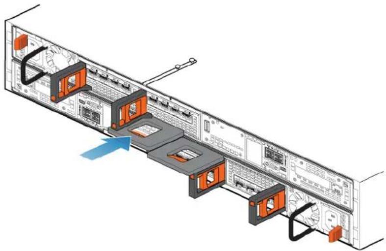
natural_image
Diagram of a server rack with orange connectors and labeled ports, showing internal layout and connection points (no text or symbols present)- Pull the orange release trigger and push in gently to re-engage the locking mechanism.
If the black release tab comes out when pulled, the locking mechanism is not engaged.
Rebooting an SP assembly into Normal Mode
Before you begin
If you removed the SP assembly during the replacement, wait about 10-15 minutes after reinserting the SP assembly into the system to allow the SP assembly to fully reboot into Service Mode. Ensure that the SP assembly fault LED is flashing alternating amber and blue (1 Hz) before continuing.
Note
If you attempt this task before the SP assembly has completed its automatic reboot into Service Mode, the attempt to reboot into Normal mode fails.
Reboot the recently serviced SP assembly into Normal Mode using the procedure that follows:
Procedure
- Open Unisphere and select Service, then Service Tasks.
- Under the name of the SP assembly where you installed the new part, select Reboot and the click Execute.
- When prompted, enter the service password to put the SP assembly into Normal Mode.
It may take up to 15 minutes for the system to complete its reboot, and return to normal mode.
Verifying the operation of the new part in Unisphere
Verify that the new part is recognized by your system, and operating correctly.
Procedure
- In Unisphere, select System View.
- On the Summary page, confirm that the system status is OK.
- Select the Enclosures page.
- Verify that the part appears with the OK status in the enclosure view. You may need to refresh Unisphere by clicking on the refresh icon next to the Enclosures view.
If the system health monitor shows the part as faulted, contact your service provider.
Returning a faulted part
We appreciate the return of defective material within 5 business days (for US returns). For International customers, please return defective material within 5-10 business days. All instructions and material required to return your defective part were supplied with your good part shipment.
Procedure
- Package the faulted part in the shipping box that contained the replacement part, and seal the box.
- Ship the failed part to your service provider as described in the instructions that were included with the replacement part.
- (Optional) For more information about returning customer-replaceable parts, from Unisphere, click Support > Replace Disk Drives, Power Supplies, and Other Parts > Return a Part to display the part return instructions.
If your screen does not show the Return a Part option, contact your service provider for instructions on what to do next.
Replace an M.2 SSD
Take the following actions to remove the faulted M.2 SSD and install the replacement M.2 SSD into the system.
The M.2 SSD are located within the SP assembly. You can access the M.2 SSD by removing the SP assembly from the chassis and opening the top cover.
Identifying and locating the faulted part in Unisphere
Before you replace a faulted part, locate its placement within the storage system.
Procedure
- In Unisphere, select System View.
- Select the Enclosures page.
- Locate the faulted part marked orange, and displayed in the Enclosures view.
Preparing the storage processor (SP) for service
To protect your system from accidental data loss during this maintenance activity, prepare the SP for service. You prepare the SP for service by putting it in Service Mode.
Entering Service Mode stops I/O on the SP so that service tasks can be safely performed.
Note
Both SPs must NOT be in Service Mode at the same time.
Procedure
- Open Unisphere and select Service, then Service Tasks.
- Under the name of the storage processor where you will install the new part, select Enter Service Mode and then click Execute.
- When prompted, enter the Service Password to put the SP into Service Mode.
- (Optional) Either refresh your browser or follow the on-screen instructions to restore full-functionality to Unisphere.
When placing the primary storage processor into Service Mode, Unisphere will become momentarily unresponsive (about one minute) as the management services transfer over to the other SP. - Return to cabinet with the system and locate the SP in the DPE from the back of the cabinet.
- Wait until the SP fault LED is flashing alternating amber and blue before continuing to the next task.
The SP fault LED will flash alternating amber and blue while the SP remains in Service mode and is receiving active power.
Figure 95 Storage processor assembly LEDs

Table 9 Storage processor assembly LEDs
| LED Location State Description | |||
| Storage processor assembly fault | 1 | Amber Fault has occurred. | |
| Blue A management IP address has been assigned. | |||
| Amber or blue blinking | System is booting. | ||
| Blue and amber alternating (blue for 3 seconds) | System not initialized. A management IP address has not been assigned. | ||
| Blue and amber alternating at one second intervals | Storage processor assembly in Service Mode. | ||
| Off No fault has occurred, normal operation. | |||
| Storage processor assembly power | 2 | Green Storage | processor assembly is on (main power). |
| Green blinking | Storage processor assembly is initializing a serial over LAN session (Standby Mode). | ||
| Off Storage processor assembly is off. | |||
Remove the SP assembly
This procedure describes how to remove a SP assembly from the chassis. There are two SP assemblies. The top SP assembly is considered to be upside-down and mirrors the bottom SP assembly. The illustration shows the removal of the bottom SP assembly. The procedure for removing the top SP assembly is the same.
CAUTION
Do not remove a SP assembly while the "Unsafe to remove" LED is lit.
Procedure
- Rotate the power cable retention bail to the left (right for top power supply). Disconnect the power cable from the power supply.
Note
If the I/O module and network cables are not already labeled, label them clearly for reconnecting later.
Figure 96 Removing the power cable

- Disconnect the network and all other cables from the back of the I/O modules and network ports on the SP assembly.
Note
Do not remove any cables from the other SP assembly.
- Pull the orange release trigger while gently pushing in on the SP assembly.
The hook disengages from the locking mechanism, and the release tab slides out.
Note
The SP assembly comes completely out of the chassis. Be prepared to support the SP assembly to avoid dropping it.
Figure 97 Disengaging the locking mechanism

natural_image
3D technical illustration of a server rack with two orange panels and internal components (no text or symbols)- Use the release handle to pull the SP assembly outward enough to grasp the sides with both hands. Then, with both hands supporting the SP assembly, pull the SP assembly fully out of the enclosure.
Figure 98 Removing the SP assembly

natural_image
Diagram of a server rack with attached hardware components and a blue arrow indicating a loading or movement (no text or symbols present)- Place the SP assembly on a clean, flat, static-free work surface.
Remove the top cover from the SP assembly
Before you begin
Ensure that the internal battery has powered off before removing the top cover. After removing the SP assembly from the rack, wait at least 30 seconds, or until you hear the internal battery power off.
Procedure
- While pushing down the two blue release buttons, slide the top cover towards the rear of the system, until it stops.
Figure 99 Releasing the top cover

natural_image
Isometric view of a rectangular electronic device with two blue arrows pointing to its top panel (no text or symbols present)- Lift the top cover upward and remove it from the SP assembly.
Figure 100 Removing the top cover
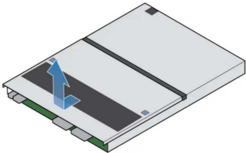
natural_image
3D diagram of a device with a blue arrow pointing to a component, no text or symbols presentRemove the faulted M.2 SSD
Procedure
- Locate the M.2 SSD adaptor in the SP assembly.
The M.2 SSD adaptor is identified by the blue retaining tabs.
-
Depress the blue retaining tabs downward to free the M.2 SSD adaptor from its slot.
-
Touching only the outside edges of the M.2 SSD adaptor, remove the M.2 SSD adaptor.
Figure 101 Removing the M.2 SSD adaptor
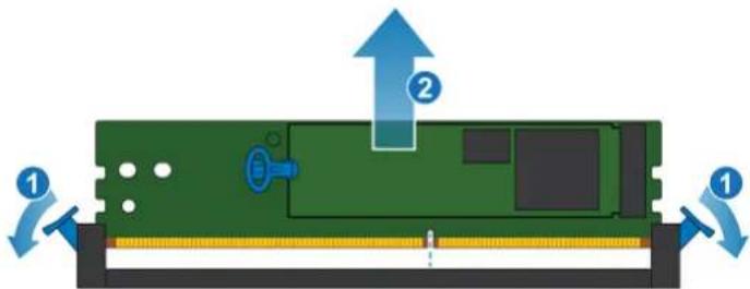
-
Identify the faulted M.2 SSD. One is labeled DRIVE 0 and the other is labeled DRIVE 1.
-
On the faulted M.2 SSD, gently pull the handle on the release tab to separate it from the tab holding it in place.
-
Pull straight up on the pull tab to free it from the M.2 SSD adaptor.
-
Remove the M.2 SSD from the M.2 SSD adaptor.
Figure 102 Removing the M.2 SSD from the M.2 SSD adaptor
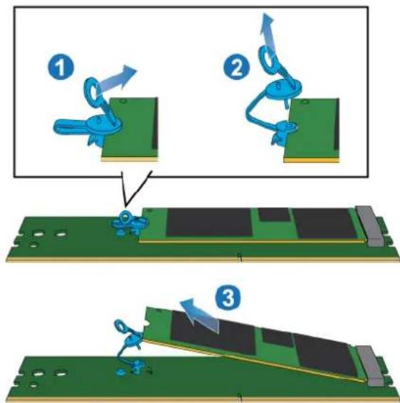
Install the M.2 SSD
Procedure
- Place the M.2 SSD into the M.2 SSD adaptor.
- Align the blue tab on the replacement M.2 SSD with the slot on the M.2 SSD adaptor and gently push it into place.
- Connect the pull tab to the blue adapter.
Figure 103 Installing the M.2 SSD into the M.2 SSD adaptor
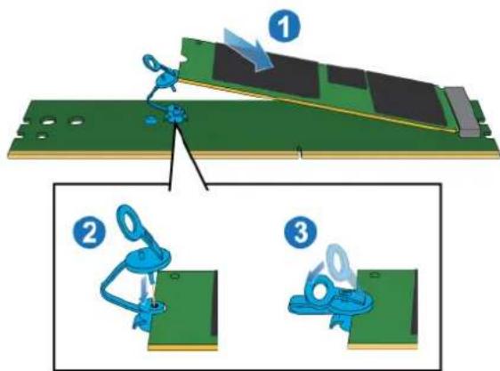
- Touching only the outside edges of the M.2 SSD adaptor, align the M.2 SSD adaptor with the connector.
- Firmly push the M.2 SSD adaptor straight down into the connector.
When the M.2 SSD adaptor is fully seated, you will hear a snap, and feel the connector latches click into place.
Figure 104 Installing the M.2 SSD adaptor
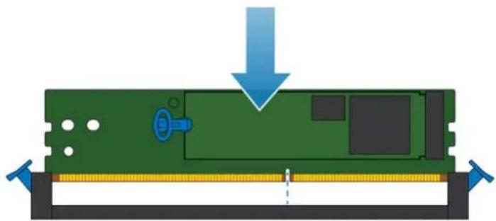
natural_image
Diagram of a mechanical assembly with a green component and blue arrow indicating downward motion (no text or symbols)Install the top cover on the SP assembly
Procedure
- Position the top cover over the SP assembly and align it with the slots in the sides at the rear of the SP assembly.
Figure 105 Aligning the top cover
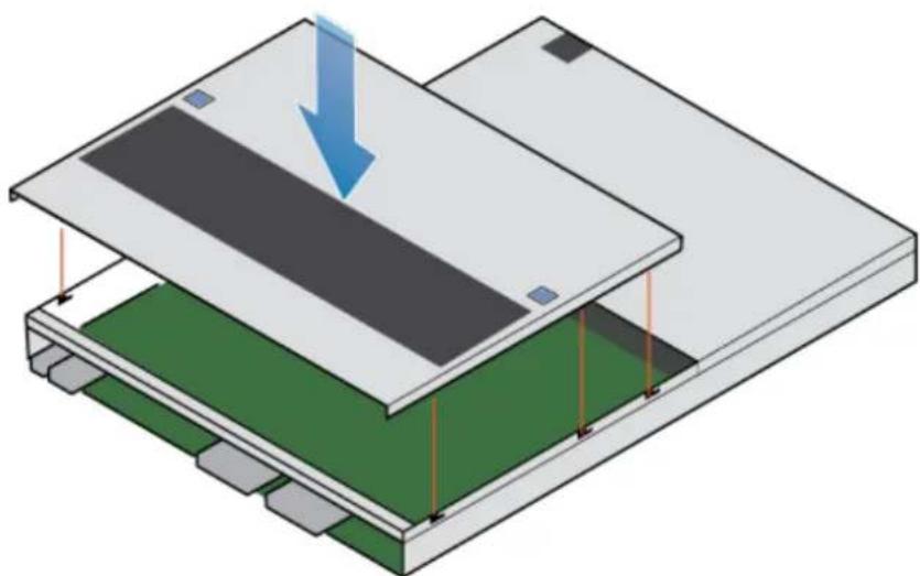
natural_image
Isometric diagram of a layered electronic device with a blue arrow indicating downward motion (no text or symbols)- Pull the top cover forward to secure it in place.
Figure 106 Securing the top cover

natural_image
Isometric view of a rectangular electronic device with a blue arrow pointing to its internal structure (no text or symbols)Install the SP assembly
Procedure
- Align the pins on the top of the SP assembly with the grooves on the top of the chassis.
- Slide the SP assembly into the chassis until it stops, about halfway in.
Figure 107 Sliding the SP assembly halfway into the chassis
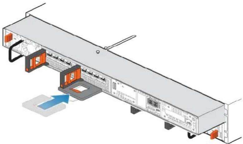
natural_image
Diagram of a server rack with orange ports and connected cables, showing internal components and a blue arrow indicating a loading or connection (no text or symbols present)- Pull the black release tab out completely, and slide the rest of the SP assembly back into the chassis.
The black release tab slides back into the system as it is inserted.
Figure 108 Installing the SP assembly

natural_image
Diagram of a server rack with orange connectors and labeled ports, showing internal layout and connection points (no text or symbols present)- Pull the orange release trigger and push in gently to re-engage the locking mechanism.
If the black release tab comes out when pulled, the locking mechanism is not engaged.
Rebooting an SP assembly into Normal Mode
Before you begin
If you removed the SP assembly during the replacement, wait about 10-15 minutes after reinserting the SP assembly into the system to allow the SP assembly to fully reboot into Service Mode. Ensure that the SP assembly fault LED is flashing alternating amber and blue (1 Hz) before continuing.
Note
If you attempt this task before the SP assembly has completed its automatic reboot into Service Mode, the attempt to reboot into Normal mode fails.
Reboot the recently serviced SP assembly into Normal Mode using the procedure that follows:
Procedure
- Open Unisphere and select Service, then Service Tasks.
- Under the name of the SP assembly where you installed the new part, select Reboot and the click Execute.
- When prompted, enter the service password to put the SP assembly into Normal Mode.
It may take up to 15 minutes for the system to complete its reboot, and return to normal mode.
Verifying the operation of the new part in Unisphere
Verify that the new part is recognized by your system, and operating correctly.
Procedure
- In Unisphere, select System View.
- On the Summary page, confirm that the system status is OK.
- Select the Enclosures page.
- Verify that the part appears with the OK status in the enclosure view. You may need to refresh Unisphere by clicking on the refresh icon next to the Enclosures view.
If the system health monitor shows the part as faulted, contact your service provider.
Returning a faulted part
We appreciate the return of defective material within 5 business days (for US returns). For International customers, please return defective material within 5-10 business days. All instructions and material required to return your defective part were supplied with your good part shipment.
Procedure
- Package the faulted part in the shipping box that contained the replacement part, and seal the box.
- Ship the failed part to your service provider as described in the instructions that were included with the replacement part.
- (Optional) For more information about returning customer-replaceable parts, from Unisphere, click Support > Replace Disk Drives, Power Supplies, and Other Parts > Return a Part to display the part return instructions.
If your screen does not show the Return a Part option, contact your service provider for instructions on what to do next.
Replace an SP assembly
Take the following actions to remove the faulted SP assembly from the enclosure and install the replacement SP assembly.
Identifying and locating the faulted part in Unisphere
Before you replace a faulted part, locate its placement within the storage system.
Procedure
- In Unisphere, select System View.
- Select the Enclosures page.
- Locate the faulted part marked orange, and displayed in the Enclosures view.
Preparing the storage processor (SP) for service
To protect your system from accidental data loss during this maintenance activity, prepare the SP for service. You prepare the SP for service by putting it in Service Mode.
Entering Service Mode stops I/O on the SP so that service tasks can be safely performed.
Note
Both SPs must NOT be in Service Mode at the same time.
Procedure
- Open Unisphere and select Service, then Service Tasks.
- Under the name of the storage processor where you will install the new part, select Enter Service Mode and then click Execute.
-
When prompted, enter the Service Password to put the SP into Service Mode.
-
(Optional) Either refresh your browser or follow the on-screen instructions to restore full-functionality to Unisphere.
When placing the primary storage processor into Service Mode, Unisphere will become momentarily unresponsive (about one minute) as the management services transfer over to the other SP.
-
Return to cabinet with the system and locate the SP in the DPE from the back of the cabinet.
-
Wait until the SP fault LED is flashing alternating amber and blue before continuing to the next task.
The SP fault LED will flash alternating amber and blue while the SP remains in Service mode and is receiving active power.
Figure 109 Storage processor assembly LEDs
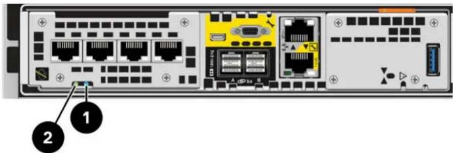
Table 10 Storage processor assembly LEDs
| LED Location State Description | |||
| Storage processor assembly fault | 1 | Amber Fault has occurred. | |
| Blue A management IP address has been assigned. | |||
| Amber or blue blinking | System is booting. | ||
| Blue and amber alternating (blue for 3 seconds) | System not initialized. A management IP address has not been assigned. | ||
| Blue and amber alternating at one second intervals | Storage processor assembly in Service Mode. | ||
| Off No fault has occurred, normal operation. | |||
| Storage processor assembly power | 2 | Green Storage | processor assembly is on (main power). |
| Green blinking | Storage processor assembly is initializing a serial over LAN session (Standby Mode). | ||
| Off Storage processor assembly is off. | |||
Remove the SP assembly
This procedure describes how to remove a SP assembly from the chassis. There are two SP assemblies. The top SP assembly is considered to be upside-down and mirrors the bottom SP assembly. The illustration shows the removal of the bottom SP assembly. The procedure for removing the top SP assembly is the same.
CAUTION
Do not remove a SP assembly while the "Unsafe to remove" LED is lit.
Procedure
- Rotate the power cable retention bail to the left (right for top power supply). Disconnect the power cable from the power supply.
Note
If the I/O module and network cables are not already labeled, label them clearly for reconnecting later.
Figure 110 Removing the power cable
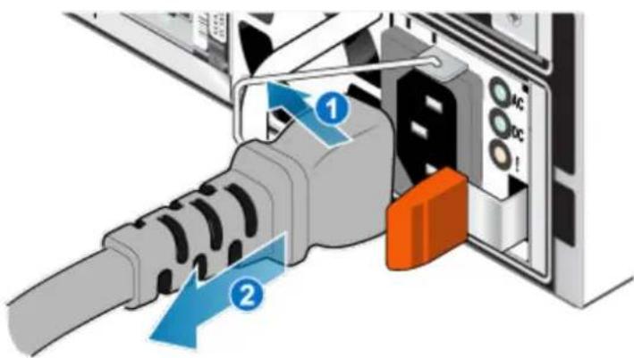
- Disconnect the network and all other cables from the back of the I/O modules and network ports on the SP assembly.
Note
Do not remove any cables from the other SP assembly.
- Pull the orange release trigger while gently pushing in on the SP assembly.
The hook disengages from the locking mechanism, and the release tab slides out.
Note
The SP assembly comes completely out of the chassis. Be prepared to support the SP assembly to avoid dropping it.
Figure 111 Disengaging the locking mechanism

natural_image
3D technical illustration of a server rack with orange and gray components, showing internal layout and ventilation slots (no text or symbols)- Use the release handle to pull the SP assembly outward enough to grasp the sides with both hands. Then, with both hands supporting the SP assembly, pull the SP assembly fully out of the enclosure.
Figure 112 Removing the SP assembly

natural_image
Diagram of a server rack with attached hardware components and a blue arrow indicating a loading or movement (no text or symbols present)- Place the SP assembly on a clean, flat, static-free work surface.
Remove the top cover from the SP assembly
Before you begin
Ensure that the internal battery has powered off before removing the top cover. After removing the SP assembly from the rack, wait at least 30 seconds, or until you hear the internal battery power off.
Procedure
- While pushing down the two blue release buttons, slide the top cover towards the rear of the system, until it stops.
Figure 113 Releasing the top cover

natural_image
Isometric view of a rectangular electronic device with two blue arrows pointing to its top panel (no text or symbols present)- Lift the top cover upward and remove it from the SP assembly.
Figure 114 Removing the top cover
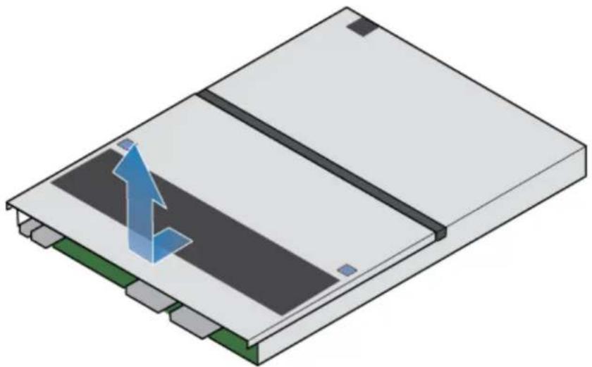
natural_image
Isometric view of a rectangular electronic component with a blue arrow indicating a directional change or force, no text or symbols present.Transfer parts from the faulted SP assembly to the replacement SP assembly
Transfer the following components from the faulted SP assembly to the corresponding locations in the replacement SP assembly.
To help ensure the correct placement in the enclosure, transfer only one component at a time.
• Transfer the power supply
• Transfer the I/O module and fillers
• Transfer the embedded module
• Transfer the internal M.2 boot module
• Transfer DIMMs
• Transfer internal fans
• Transfer the internal battery backup module
Remove the internal battery backup module
Procedure
- Remove the internal battery backup module cover.
- Disconnect the internal battery backup module cable from the motherboard by squeezing the white tab and lifting upward.
- Push down on the two blue retaining tabs. At the same time, pull up on the blue pull tab.
Figure 115 Releasing the internal battery backup module
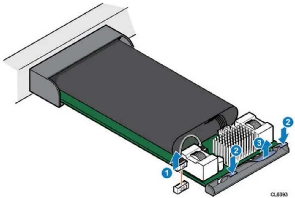
- Lift the internal battery backup module away from the motherboard.
Figure 116 Removing the internal battery backup module
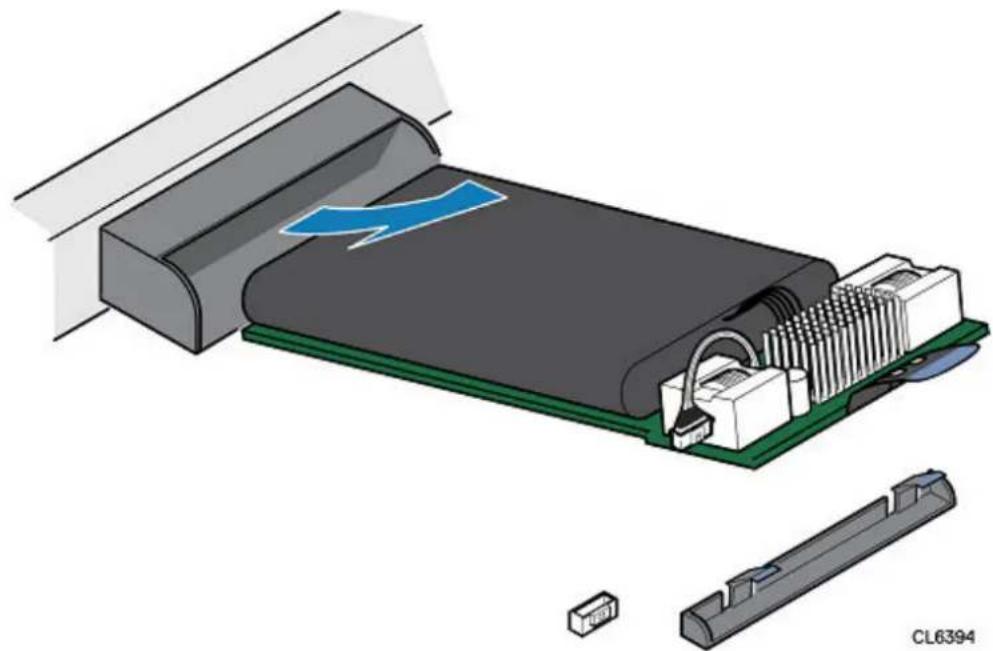
natural_image
Exploded view diagram of an electronic device showing internal components and a blue lightning bolt (no text or symbols)- Remove the cable from the internal battery backup module by squeezing the white tab and lifting upward.
Install the internal battery backup module
Procedure
-
Connect the internal battery backup module cable to the internal battery backup module.
-
Place the internal battery backup module into position on the motherboard.
Figure 117 Installing the internal battery backup module

natural_image
Diagram of an electronic device showing internal components and a blue arrow indicating flow or movement (no text or symbols)- Press downward on the internal battery backup module to lock it into position.
- Connect the internal battery backup module cable to the motherboard.
Figure 118 Securing the internal battery backup module
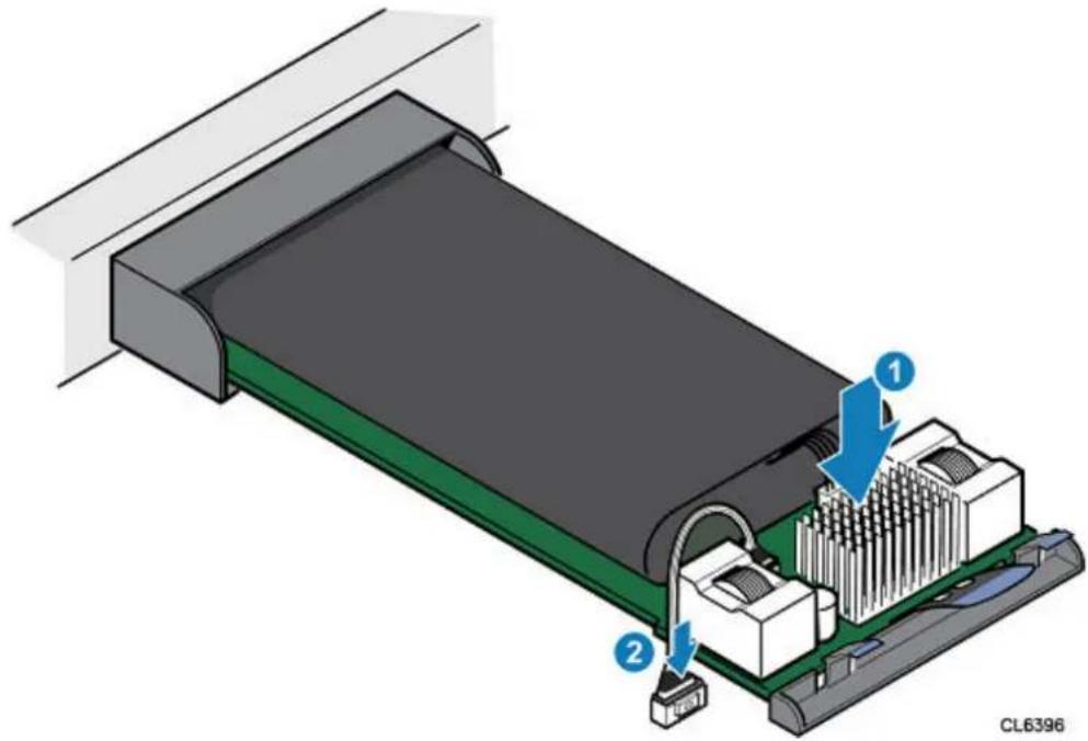
- Install the internal battery backup module cover.
Install the top cover on the SP assembly
Procedure
- Position the top cover over the SP assembly and align it with the slots in the sides at the rear of the SP assembly.
Figure 119 Aligning the top cover

natural_image
Isometric diagram of a layered electronic device with a blue arrow indicating downward motion (no text or symbols)- Pull the top cover forward to secure it in place.
Figure 120 Securing the top cover
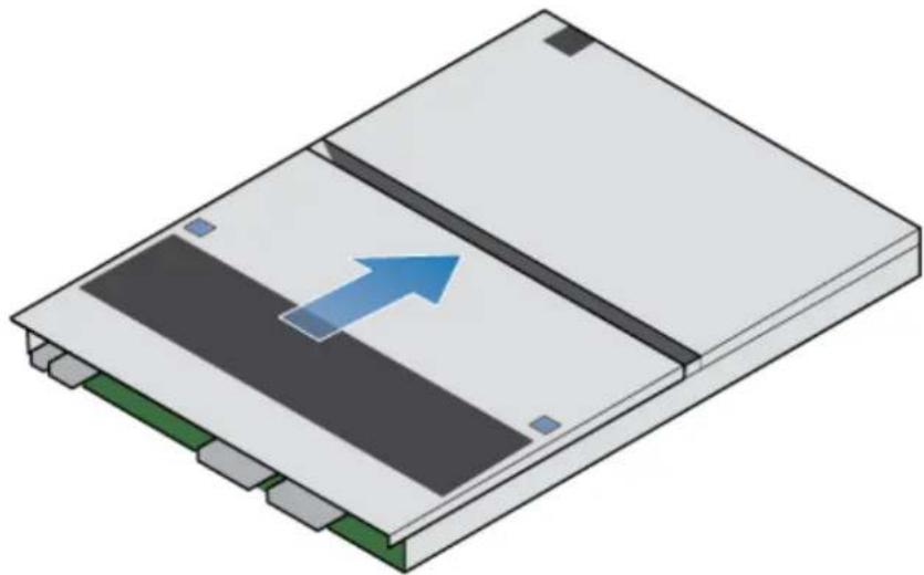
natural_image
Isometric view of a rectangular electronic device with a blue arrow pointing to its internal structure (no text or symbols)Install the SP assembly
Procedure
- Align the pins on the top of the SP assembly with the grooves on the top of the chassis.
- Slide the SP assembly into the chassis until it stops, about halfway in.
Figure 121 Sliding the SP assembly halfway into the chassis
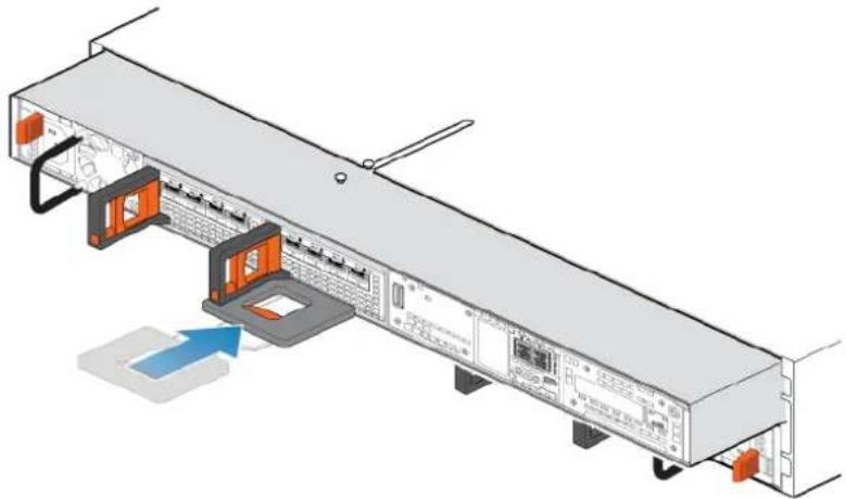
natural_image
Diagram of a server rack with orange connectors and drive bays, showing internal components and connection points (no text or labels)- Pull the black release tab out completely, and slide the rest of the SP assembly back into the chassis.
The black release tab slides back into the system as it is inserted.
Figure 122 Installing the SP assembly

natural_image
Isometric view of a server rack with orange and black components, showing internal layout and ventilation slots (no text or labels)- Pull the orange release trigger and push in gently to re-engage the locking mechanism.
If the black release tab comes out when pulled, the locking mechanism is not engaged.
Rebooting an SP assembly into Normal Mode
Before you begin
If you removed the SP assembly during the replacement, wait about 10-15 minutes after reinserting the SP assembly into the system to allow the SP assembly to fully reboot into Service Mode. Ensure that the SP assembly fault LED is flashing alternating amber and blue (1 Hz) before continuing.
Note
If you attempt this task before the SP assembly has completed its automatic reboot into Service Mode, the attempt to reboot into Normal mode fails.
Reboot the recently serviced SP assembly into Normal Mode using the procedure that follows:
Procedure
- Open Unisphere and select Service, then Service Tasks.
- Under the name of the SP assembly where you installed the new part, select Reboot and the click Execute.
- When prompted, enter the service password to put the SP assembly into Normal Mode.
It may take up to 15 minutes for the system to complete its reboot, and return to normal mode.
Verifying the operation of the new part in Unisphere
Verify that the new part is recognized by your system, and operating correctly.
Procedure
- In Unisphere, select System View.
- On the Summary page, confirm that the system status is OK.
- Select the Enclosures page.
- Verify that the part appears with the OK status in the enclosure view. You may need to refresh Unisphere by clicking on the refresh icon next to the Enclosures view.
If the system health monitor shows the part as faulted, contact your service provider.
Returning a faulted part
We appreciate the return of defective material within 5 business days (for US returns). For International customers, please return defective material within 5-10 business days. All instructions and material required to return your defective part were supplied with your good part shipment.
Procedure
- Package the faulted part in the shipping box that contained the replacement part, and seal the box.
- Ship the failed part to your service provider as described in the instructions that were included with the replacement part.
- (Optional) For more information about returning customer-replaceable parts, from Unisphere, click Support > Replace Disk Drives, Power Supplies, and Other Parts > Return a Part to display the part return instructions.
If your screen does not show the Return a Part option, contact your service provider for instructions on what to do next.
APPENDIX A
Configuration Worksheet
This appendix contains a worksheet to collect and record information and to use as a guide to start setting up your storage system.
Topics include:
- Configuration worksheet....118
Configuration worksheet
Use this worksheet to collect and record information to start setting up your storage system using the following:
• Online Support
- Connection Utility
• Unisphere Initial Configuration Wizard
This worksheet should be used in conjunction with the information in the previous chapter. Refer to the Connection Utility and Unisphere Online Help for additional guidance for setting up your storage system. In the respective user interface, click the ? icon to display its online help.
Note
Sites with restricted Internet access must obtain the Connection Utility software and product license keys in advance to configure the system. Go to the Unity Info Hub at http://bit.ly/unityinfohub for detailed instructions.
Online Support
Enter the following information related to your Online Support account:
| Item | Value |
| Online Support account:Go to support.emc.com to create your Online Support account.Your username and password will be required for the Unisphere Initial Configuration wizard. |
Connection Utility
Enter the following information related to the system management address:
| Item | Value |
| Storage system Product ID / Serial Number:Refer to the serial number tag on the front of the DPE component for the system ID.Use this ID in the Connection Utility to auto-discover a storage system on a subnet. | |
| Name:If you obtained the system's IP address through DHCP, use the system serial number for the name. | |
| Management IP Address:Management IPv4 and/or IPv6 address to assign to the storage system. | |
| Subnet Mask (IPv4 only): | |
| Item Value | |
| IP address mask that identifies the range of IP addresses in the subnet where storage system is connected. | |
| Gateway:Default gateway IP address of the storage system management interface. | |
| Prefix Length (IPv6 only):The number of significant bits in the address that will be used for routing purposes. |
Unisphere
Enter the following information to initially log into Unisphere:
| Item Value | |
| Unisphere login information:When logging into Unisphere for the first time, use the default system account user name and password | User Name:adminPassword:Password123# |
Initial Configuration Wizard
The Initial Configuration Wizard walks you through the initial set up of Unisphere and prepares the system for use. The first time the wizard launches, you will need to access the End User License Agreement (EULA) and install Unisphere licenses. Use the following list of screens and related actions as a guide to the initial configuration process.
| Screen Name | Action |
| Copyright Accept the EULA. | |
| Unisphere Password Set the Unisphere admin and service passwords | |
| Unisphere Licenses Obtain your license file. | Unisphere license file online and upload your license file. |
| DNS servers (Manual configuration) | Enter the network name or IP address of one or more DNS servers. |
| NoteA DNS server is required for EMC Secure Remote Services (ESRS). | |
| NTP Servers Enter the network | name or IP address of one or more NTP (Network Time Protocol) servers. |
| Screen Name Action | |
| NoteAn NTP server must be configured before you can create a NAS server with SMB (CIFS) shares that use Windows Active Directory (required for multiprotocol). It is also recommended that you configure an NTP server on both systems in order for the replication feature to work correctly. | |
| FAST Cache and Storage Pools | Create FAST Cache (if supported) and storage pools, or configure these items later. |
| Alert Settings Configure alert notifications by entering the email addresses to which alerts should be sent, set the severity level for these alerts, and configure an SMTP server. | |
| Proxy Server (optional) Enter the Protocol, IP address, and Proxy Server username and password. | |
| EMC Support Credentials Enter your EMC Online Support username and password. | |
| Customer Information Enter your customer contact information, including name, email, and office phone number. EMC Support will use this information to get in contact with you in response to an issue. | |
| EMC Secure Remote Services Enable and configure EMC Secure Remote Services (ESRS) to send system information to EMC and expedite issue resolution. | |
| iSCSI Interfaces (optional) Refer to the Unisphere Online Help for more information about configuring iSCSI interfaces. | |
| NAS Servers (optional) Refer to the NAS Server Wizard Online Help for more information about configuring NAS servers. | |
Note
Visit the Unity Info Hub page at http://bit.ly/unityinfohub for more information about configuring your storage system.
APPENDIX B
Safety precautions for handling replaceable units
Review these safety considerations before replacing any parts to avoid damage to your system.
- Handling replaceable units....122
- Standard touch point colors....125
Handling replaceable units
This section describes the precautions that you must take and the general procedures that you must follow when removing, installing, and storing any replaceable unit.
Avoiding electrostatic discharge (ESD) damage
When replacing or installing hardware units, you can inadvertently damage the sensitive electronic circuits in the equipment by simply touching them. Electrostatic charge that has accumulated on your body discharges through the circuits. If the air in the work area is very dry, running a humidifier in the work area will help decrease the risk of ESD damage. Follow the procedures below to prevent damage to the equipment.
Be aware of the following requirements:
- Provide enough room to work on the equipment.
- Clear the work site of any unnecessary materials or materials that naturally build up electrostatic charge, such as foam packaging, foam cups, cellophane wrappers, and similar items.
- Do not remove replacement or upgrade units from their antistatic packaging until you are ready to install them.
- Before you begin service, gather together the ESD kit and all other materials you will need.
- Once servicing begins, avoid moving away from the work site; otherwise, you may build up an electrostatic charge.
-
Use ESD anti-static gloves or an ESD wristband (with strap). If using an ESD wristband with a strap:
-
Attach the clip of the ESD wristband to the ESD bracket or bare metal on a cabinet/rack or enclosure.
- Wrap the ESD wristband around your wrist with the metal button against your skin.
■ If a tester is available, test the wristband.
Emergency procedures (without an ESD kit)
In an emergency when an ESD kit is not available, use the following precautions to reduce the possibility of an electrostatic discharge by ensuring that your body and the subassembly are at the same electrostatic potential.
NOTICE
These precautions are not a substitute for the use of an ESD kit. Follow them only in the event of an emergency.
- Before touching any unit, touch a bare (unpainted) metal surface of the cabinet/rack or enclosure.
- Before removing any unit from its antistatic bag, place one hand firmly on a bare metal surface of the cabinet/rack or enclosure, and at the same time, pick up the unit while it is still sealed in the antistatic bag. Once you have done this, do not
move around the room or touch other furnishings, personnel, or surfaces until you have installed the unit.
- When you remove a unit from the antistatic bag, avoid touching any electronic components and circuits on it.
- If you must move around the room or touch other surfaces before installing a unit, first place the unit back in the antistatic bag. When you are ready again to install the unit, repeat these procedures.
Hardware acclimation times
Systems and components must acclimate to the operating environment before applying power. This requires the unpackaged system or component to reside in the operating environment for up to 16 hours in order to thermally stabilize and prevent condensation.
Table 11 on page 123 helps you determine the precise amount of stabilization time required.
Table 11 Hardware acclimation times (systems and components)
| If the last 24 hours of the TRANSIT/STORAGE environment was this: | ...and the OPERATING environment is this: | ...then let the system or component acclimate in the new environment this many hours: | |
| Temperature Humidity | |||
| Nominal 68-72°F (20-22°C) | Nominal 40-55% RH | Nominal 68-72°F (20-22°C) 40-55% RH | 0-1 hour |
| Cold <68°F (20°C) | Dry <30% RH | <86°F (30°C) 4 hours | |
| Cold <68°F (20°C) | Damp ≥30% RH | <86°F (30°C) 4 hours | |
| Hot >72°F (22°C) | Dry <30% RH | <86°F (30°C) 4 hours | |
| Hot >72°F (22°C) | Humid 30-45% RH | <86°F (30°C) 4 hours | |
| Humid 45-60% RH | <86°F (30°C) 8 hours | ||
| Humid ≥60% RH | <86°F (30°C) 16 hours | ||
| Unknown <86°F (30°C) 16 hours | |||
NOTICE
- If there are signs of condensation after the recommended acclimation time has passed, allow an additional eight (8) hours to stabilize.
- Systems and components must not experience changes in temperature and humidity that are likely to cause condensation to form on or in that system or component. Do not exceed the shipping and storage temperature gradient of 45^ F/hr ( 25^ C/hr).
- Do NOT apply power to the system for at least the number of hours specified in Table 11 on page 123. If the last 24 hours of the transit/storage environment is unknown, then you must allow the system or component 16 hours to stabilize in the new environment.
Removing, installing, or storing replaceable units
Use the following precautions when removing, handling, or storing replaceable units:
CAUTION
Some replaceable units have the majority of their weight in the rear of the component. Ensure that the back end of the replaceable unit is supported while installing or removing it. Dropping a replaceable unit could result in personal injury or damage to the equipment.
NOTICE
- For a module that must be installed into a slot in an enclosure, examine the rear connectors on the module for any damage before attempting its installation.
- A sudden jar, drop, or even a moderate vibration can permanently damage some sensitive replaceable units.
- Do not remove a faulted replaceable unit until you have the replacement available.
- When handling replaceable units, avoid electrostatic discharge (ESD) by wearing ESD anti-static gloves or an ESD wristband with a strap. For additional information, refer to Avoiding electrostatic discharge (ESD) damage on page 122.
- Avoid touching any exposed electronic components and circuits on the replaceable unit.
- Never use excessive force to remove or install a replaceable unit. Take time to read the instructions carefully.
- Store a replaceable unit in the antistatic bag and the specially designed shipping container in which you received it. Use the antistatic bag and special shipping container when you need to return the replaceable unit.
- Replaceable units must acclimate to the operating environment before applying power. This requires the unpackaged component to reside in the operating environment for up to 16 hours in order to thermally stabilize and prevent condensation. Refer to Hardware acclimation times on page 123 to ensure the replaceable unit has thermally stabilized to the operating environment.
NOTICE
Your storage system is designed to be powered on continuously. Most components are hot swappable; that is, you can replace or install these components while the storage system is running. However, the system requires that:
- Front bezels should always be attached to ensure EMI compliance. Make sure you reattach the bezel after replacing a component.
- Each slot should contain a component or filler panel to ensure proper air flow throughout the system.
Unpacking a part
Procedure
- Wear ESD gloves or attach an ESD wristband to your wrist and the enclosure in which you are installing the part.
- Unpack the part and place it on a static-free surface.
- If the part is a replacement for a faulted part, save the packing material to return the faulted part.
Standard touch point colors
Touch points are component locations where you can:
- Grip the hardware to remove or install a component.
- Open or close a latch.
- Turn a knob to open, close, or adjust a component.
Standard touch point colors are terra-cotta (orange) or blue.
Note
Within this documentation, the color orange is used instead of terra-cotta for simplicity.
Table 12 Standard touch point colors
| Touch point color | Description |
| Terra-cotta(orange) | This color indicates that you can perform the task, such as remove a component with a terra-cotta (orange) lever, while the system remains powered (up/on).NoteSome tasks may require additional steps. |
| Blue This color indicates that a shutdown of the system or component is required before you can perform the task, such as removing a component with a blue lever. | |
 | |