PT510 - Receiver Pyle - Free user manual and instructions
Find the device manual for free PT510 Pyle in PDF.

User questions about PT510 Pyle
0 question about this device. Answer the ones you know or ask your own.
Ask a new question about this device
Download the instructions for your Receiver in PDF format for free! Find your manual PT510 - Pyle and take your electronic device back in hand. On this page are published all the documents necessary for the use of your device. PT510 by Pyle.
USER MANUAL PT510 Pyle
natural_image
Abstract black-and-white logo with concentric curved lines and a central 'P' shape (no text or symbols)PYLE®
240 Watt Public Address Power Amplifier, w/ 70V Output & Mic Talkover, USB/SD Card MP3 Player, Built-in FM Radio
text_image
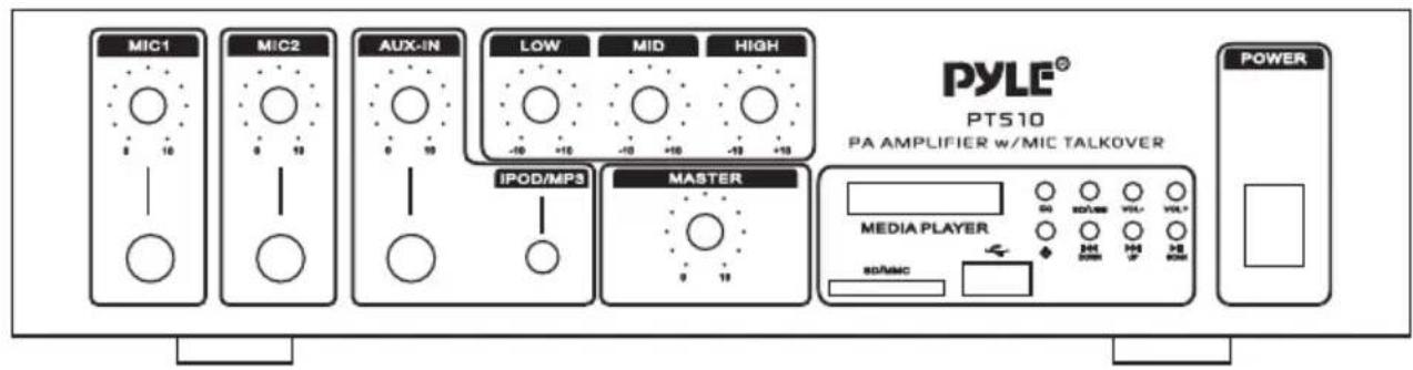
MIC1 MIC2 AUX-IN LOW MID HIGH IPOD/MP3 MASTER PYLE® PT510 PA AMPLIFIER w/MIC TALKOVER MEDIA PLAYER SDAMC POWERMODEL:PT510 PA AMPLIFIER
www.pyleaudio.com
INTRODUCTION
Your New PYLE PT510 AMPLIFIER gives you the power and versatility you need in a professional sound system.
The amplifier's wide frequency response makes it suitable for amplifying music or vocal program material. It can be used for live bands, office paging systems, public announcements, or a variety of other installations.
Please read this manual thoroughly before you attempt to set up and use the amplifier. It contains a range of installation suggestions as well as instructions to ensure safe usage. Installed properly, you can expect years of trouble-free service from this product.
FEATURES AND CONTROLS
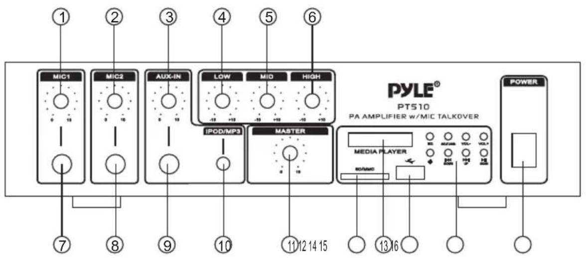
FRONT PANEL- PT510
text_image
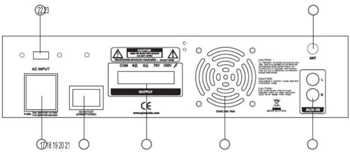
MIC1 MIC2 AUX-IN LOW MID HIGH IPOD/MP3 MASTER MEDIA PLAYER POWER PT510 PA AMPLIFIER w/MIC TALKOVER 7 8 9 10 11 12 14 15 13 16REAR PANEL-PT510
text_image
22 23 AC INPUT FUSE TOL.200 FOR 115-120V TOL.200 FOR 229-240N AC OUTLET (OFF/STITCHED) 17 18 19 20 21 CAUTION RARE OF ELECTRIC SHOCK BEET OPEN WARNING SHOCK HAZARD - DEPT ON COM 4Q 8Q 70V 100V OUTPUT CE www.aytis.edu.com COOLING PAN CAUTION: TO PROVEGET PLATESH SHOCK DO NOT USE THIS POURLED PLATE WITH AN AUTOMOBILE CABLE SHOCKS FOR ALL STOPS OUT OF ORDER THE SLABS FOR ONLY PULSE SWITCHED TO PROVEGET SLADE EXPOUSE CAUTION: SPRING/BRIGHT SUPPLY CABB BEFORE CHARGING FUEL CAUTION: FOR SUPERBOLD PROTECTION ASSEMBLY ARE IT'S NOO FOR YOUR ITEMS ONLY WITH SAME TYPE FUEL. MACE SWITCHER ANT L R AUX-INMODEL:PT510 PA AMPLIFIER
- MIC1 Volume Control
-Volume control for MIC1.
- MIC2 Volume Control
-Volume control for MIC2.
- AUX-IN VOLUME CONTROL
- Allow you to control any high level sound source inputs (by 1/4" Audio Input, 1/8" iPod/MP3 input, and RCA Audio Input to connect any high level sound source inputs).
- LOW Tone Control
- Lets you adjust the sound of bass frequency to the acoustic of a Particular performance environment.
- MID Tone Control
-Lets you adjust the sound of middle range frequency to the acoustic of a Particular performance environment.
- HIGH Tone Control
-Lets you adjust the sound of treble frequency to the acoustic of a Particular performance environment.
-
MIC1 1/4" Input Jack
-
MIC2 1/4" Input Jack
-
Audio 1/4" Input Jack
-allow you to connect any high level sound source, such as a CD player, tape deck, or tuner, to the CD/AUX jack.
- IPOD/MP3 1/8" Input Jack
- Let you easily connect the computerized MP3 Device (player) sources, such as PC (CD ROM), Laptop, Walkman, iPod, and Cell Phone, iPhone, iPad, ect.
- MASTER Volume Control
-Lets you adjust the overall sound level.
-
SD/MMC Socket for Playing SD/MMC cards.
-
Function Blue LED Display Window.
-
USB Socket for playing the USB function.
-
Keys for MP3(USB/SD/MMC) Function Control:
-EQ: Equalizer adjustment for the USB/SD.
-SD/USB: Switch between the USB and SD playing.
-Vol-/VOL+: Adjust MP3(USB/SD) volume- or volume+
- ⏻ Power on or off for MP3(USB/SD/MMC)
MODEL:PT510 PA AMPLIFIER
-DOWN/UP: Song Selection Control both for MP3(USB/SD/MMC) and FM Tuner
-PLAY/PAUSE: Play or Pause control for MP3(USB/SD/MMC) and FM Tuner.
- Power On/Off for the Whole Machine.
17.AC INPUT
-When plug the power supply cable on the machine, pls make sure the switch as above is in the proper position before operating,
18.AC OUTLET
-Unswitched AC Accessory Outlet-300W MAX.
19.Push-Terminal Connectors
-Let you easily connect the speaker wires directly to the amplifiers
20.FAN: Cooling Fan
21.AUX INPUT JACK
-Allows you to connect any high level sound source, such as a CD player, tape deck, or tuner, to the CD/AUX jack.
22.110V/220V Voltage Switch
- The amplifier has selectable input voltage from 110V/60Hz which is the standard in USA and CANADA. You can also switch the input voltage to 220V/50Hz for EUROPEAN operation. PIs make sure the switch as above is in the proper position before operating,
23.ANT
-Connect for FM Antennas
INSTALLATION GUIDELINES
Connecting the GND (GROUND) screw terminal
If you connect a low level audio input source (turntable) to the PHONO, please connect your turntable's ground wire (usually black or green) to the amplifier's GND terminal, to avoid a low frequency hum.
You can also use this screw to ground any other system connection.
Input connections
The PT 510 accept a board range of input sources, including:
Microphones (up to two simultaneously)
Compact Disc (CD) player
Cassette, Reel-to-Reel or other tape player
Radio Tuner
Magnetic Cartridge Turntable
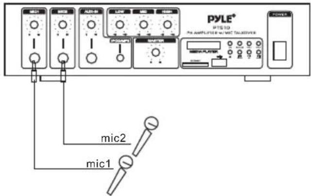
Connecting microphones
The MIC 1 and MIC 2 jacks permit you to connect two microphones with 6.35mm plug.
text_image
PYLE® PTS 10 Pre AMPLIFIER w/ MTC TALACOVER mic2 mic1Connecting a turntable
In this Situation, set the PHONO and AUX/CD SELECTOR switch to the PHONO.
Speaker connections
One or more speakers (4 or 8 – Ohm) speakers can be connected to the amplifier with or without transformers. However, before you connect any speaker to the amplifier, the total speaker impedance must be calculated in order to avoid damage to the amplifier. A total speaker impedance greater than 8 Ohms or less than 4 Ohms can be cause this damage to occur. To begin with, in order to ensure equal volume from each speaker, all connected speakers should have the same impedance.
A proper total impedance with the 4 to 8 Ohms range can be achieved by combining series and paralleled speaker connections. Please see the diagrams which follow the same impedance.
Finally, always use the shortest length of speaker wire possible of proper gauge. Usually, 18-gauge wire is adequate for lengths under 25 feet, while 16-gauge is used for greater lengths.
text_image
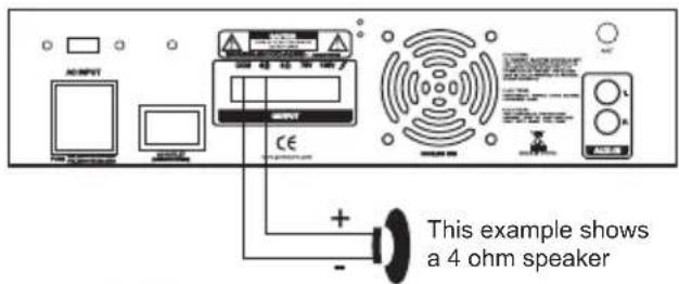
AC/REF This example shows a 4 ohm speakerSystem 1: Single speaker system
- Connect the speaker (-) terminal to the amplifier COMMON terminal
- Depending on the speaker being used, connect the speaker (+) terminal to the amplifier's 4-Ohm or 8- Ohm amplifier terminal.
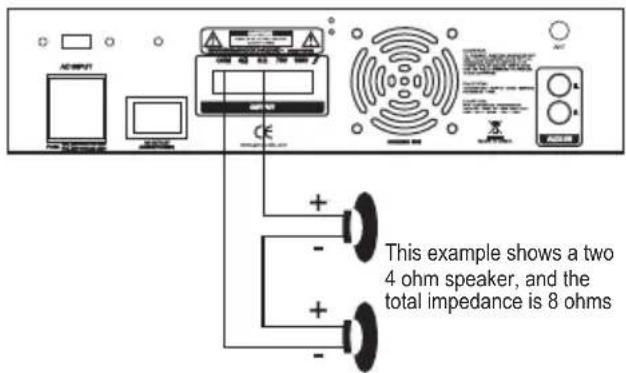
System 2: Two (or more) speakers in series
- Connect the LEFT SPEAKER (-) to the amplifier COMMON terminal.
- Connect the LEFT SPEAKER (+) to the RIGHT SPEAKER (-).
- Connect the RIGHT SPEAKER (+) to the amplifier's 4-Ohm or 8-Ohm terminal, depending on the TOTAL IMPEDANCE of the two speakers.
text_image
This example shows a two 4 ohm speaker, and the total impedance is 8 ohmsTO THE 8-OHM TERMINAL
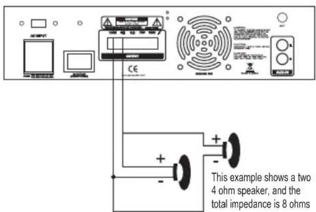
System 3: Two (or more) speakers in parallel
- Connect the LEFT SPEAKER (-) to the RIGHT SPEAKER (-).
- Connect BOTH the LEFT SPEAKER (-) and the RIGHT SPEAKER (-) to the amplifier COMMON terminal.
- Connect the LEFT SPEAKER (+) to the RIGHT SPEAKER (+).
- Connect BOTH the LEFT SPEAKER (+) and RIGHT SPEAKER (+) to the amplifier 4-Ohm or 8-Ohm terminal, depending on the TOTAL IMPEDANCE of the two speakers. If each speaker has an impedance of 8-Ohm, the total speaker impedance in this parallel configuration is 4 Ohms.
text_image
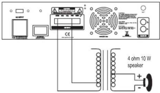
ACRIPUT CE This example shows a two 4 ohm speaker, and the total impedance is 8 ohmsSystem4: Connecting speakers with transformers
- Locate the input taps on your transformer. These taps are on side of the transformer, and are rated in watts, 10, 5, 2.5, 1.25 or 0.62. Usually, each speaker in a system uses the same wattage tap.
Connect the selected tap to the amplifier 70V RMS terminal.
If you wish a particular speaker to have a higher volume level, connect the wire from 70V RMS to a higher wattage tap on the transformer.
-
Connect the transformer's COMMON tap on the primary side to the amplifier COMMON terminal.
-
Connect the speaker's (+) terminals to the transformer's secondary tap that matches the speaker's TOTAL IMPEDANCE. Locate on the opposite side of the transformer, these secondary taps are outputs, and are rated in Ohms 4 or 8.
-
Connect the speaker's (-) terminals to the transformer's COMMON tap on the secondary side.
NOTE: Before connecting the speakers, please be sure the total wattage of the primary tap you use does not exceed the amplifier's maximum power rating.
ALSO: Avoid, where possible, multiple connections to the 70V RMS and COMMON terminals.
text_image
OUTPUT 4 ohm 10 W speaker CESpecifications
Output Power at THD 10%, 1 kHz 50W
Maximum Power 240W
THD at 1W, 1 kHz Low-Pass Filter
MIC 1....1%
MIC 2....1%
AUX/CD 1%
Frequency Response (at 1W, +/- 3 dB)
MIC 1....80 Hz - 20 kHz
MIC 2....80 Hz - 20 kHz
AUX/CD 80 Hz - 20 kHz
Input Sensitivity (at 10% THD, 1kHz)
MIC 1 2.5 mV
MIC 2 2.5 mV
AUX/CD....150mV
Signal-Noise Ratio (Input Shorted) with WTD
MIC 1....60dB
MIC 2....60dB
AUX/CD 70dB
Noise Level (Input Shorted)....0.75mV
Equalizer Control Range
100 Hz +/- 10 dB
1 kHz +/- 10 dB
8 kHz +/- 10 dB
Power Requirement
120V AC, 60 Hz/240V AC, 50 Hz
Power Fuse
120V AC 2A
240V AC 1 A
Dimensions H x W x D,
12.6x7.48x3.15 (inches)
32×19×8(cm)
Weight, (kg)
4.2KGS