
WRC613SB - Range hood WESTINGHOUSE - Free user manual and instructions
Find the device manual for free WRC613SB WESTINGHOUSE in PDF.


| Product Type | Under-cabinet range hood |
| Brand | Westinghouse |
| Model | WRC613SB |
| Installation | Under cabinet, recirculating or ducted |
| Width | 60 cm (23.6 inches) |
| Depth | Approximately 50 cm |
| Height | Approximately 15 cm (adjustable chimney) |
| Weight | Approximately 12 kg |
| Power Supply | 220-240 V, 50 Hz |
| Rated Power | 200 W |
| Max Airflow | 650 m³/h |
| Noise Level | 55 dB (max speed) |
| Number of Speeds | 3 |
| Control Type | Push buttons |
| Lighting | 2 x 20 W halogen or LED (depending on version) |
| Grease Filters | Aluminum washable filters |
| Charcoal Filter | Optional (for recirculation mode) |
| Ducting Diameter | 150 mm |
| Energy Class | A (estimated) |
| Cleaning | Wash grease filters monthly with mild detergent; clean exterior with damp cloth |
| Safety Features | Overheat protection, auto shut-off (timer optional) |
| Spare Parts | Filters, bulbs, switch available from authorized service |
| Warranty | 2 years (typical) |
| Manual Included | Yes, PDF available |
Frequently Asked Questions - WRC613SB WESTINGHOUSE
User questions about WRC613SB WESTINGHOUSE
0 question about this device. Answer the ones you know or ask your own.
Ask a new question about this device
Download the instructions for your Range hood in PDF format for free! Find your manual WRC613SB - WESTINGHOUSE and take your electronic device back in hand. On this page are published all the documents necessary for the use of your device. WRC613SB by WESTINGHOUSE.
USER MANUAL WRC613SB WESTINGHOUSE
INSTALLATION AND USER MANUAL
WRC613SB Canopy Rangehood
WRC913SB Canopy Rangehood
CONGRATULATIONS
Congratulations and thank you for choosing our canopy rangehood. We are sure you will find your new rangehood a pleasure to use. Before you use your rangehood, we recommend that you read through the whole user manual, which provides the description of the rangehood and its function.
To avoid the risks that are always present when you use an electrical appliance it is important that the canopy rangehood is installed correctly and that you read the safety instructions carefully to avoid misuse and hazards. We recommend that you keep this instruction booklet for future reference and pass it on to any future owners. After unpacking the canopy rangehood please check it is not damaged. If in doubt, do not use the appliance but contact your local Electrolux Service Centre.
Conditions of use
This appliance is intended to be used in household and similar applications such as:
• Staff kitchen areas in shops, offices and other working environments
- Farm houses
- By clients in hotels, motels and other residential type environments
• Bed and breakfast type environments.
Record model and serial number here:
Model:
Serial No: ____

TIPS & INFORMATION
IMPORTANT – CHECK FOR ANY DAMAGES OR MARKS. If you find the rangehood is damaged or marked, you must report it within 7 days if you wish to claim for damage/marks under the manufacturers warranty. This does not affect your statutory rights.
UNPACKING
Check that the cooker hood has no damage. Transportation damage should immediately be reported to the company responsible for the transportation. Damage, faults and missing details should immediately be reported to the retailer. Take care of the packing materials so that small children cannot play with them.

ENVIRONMENTAL TIPS
INFORMATION ON DISPOSAL FOR USERS
- Most of the packing materials are recyclable. Please dispose of those materials through your local recycling depot or by placing them in appropriate collection containers.
- If you wish to discard this product, please contact your local authorities and ask for the correct method of disposal.
CONTENTS
Important safety instructions 3
Description of your rangehood 5
Components list 5
Technical specifications 5
Rangehood dimensions 6
Installation 7
Using your rangehood 12
Care & maintenance 12
Troubleshooting 14
Optional ducting accessories 15
Warranty 16
IMPORTANT SAFETY INSTRUCTIONS
This manual explains the proper use of your new Westinghouse canopy rangehood. Please read this manual carefully before using the product. This manual should be kept in a safe place for handy reference. This canopy rangehood is a domestic appliance which has been manufactured and tested to comply with Australian and New Zealand Standard AS/NZS 60335.2.31.
Meanings of symbols used in this manual are shown below:

CAUTION
This symbol indicates the possibility of injury or damage to property.

This symbol indicates never to do this.

This symbol indicates always do this.

TIPS & INFORMATION
This symbol indicates tips and information about use of the appliance.

ENVIRONMENTAL TIPS
This symbol indicates tips and information about economical and ecological use of the appliance.

CAUTION
Read the following carefully to avoid an electric shock or fire.
GENERAL WARNINGS
√
The appliance must be plugged into its own dedicated 220-240V, 50Hz AC electrical outlet.
This appliance can be used by children aged from 8 years and above and persons with reduced physical, sensory or mental capabilities or lack of experience and knowledge if they have been given supervision or instruction concerning the use of the appliance in a safe way and understand the hazards involved. Children shall not play with the appliance. Cleaning and user maintenance shall not be made by children without supervision.
This canopy rangehood is not recommended for barbecues and cannot be installed for external use.
② Grease filters must be removed every four weeks (maximum) for cleaning to reduce the risk of fire.
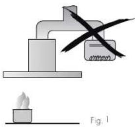
The exhaust from the canopy rangehood must not be discharged into any heating flue, which may carry combustion products from other sources. (Fig 1)
Exhaust air must not be discharged into a wall cavity, unless the cavity is designed for the purpose.
There must be adequate ventilation of the room when the canopy rangehood is used at the same time as appliances burning gas or other fuels.
√ Always cover lit gas burners with pots or pans when canopy rangehood is in use.
√ Always switch off gas burners before you remove pots or pans.
Do not leave lit gas burners exposed due to the risk of fire. (Fig 2)
The hood must always be disconnected from the electricity supply before beginning any maintenance work.
Failure to install the screws or fixing device in accordance with these instructions may result in electrical hazards.
ELECTRICAL CONNECTION
Check that the mains voltage matches with the voltage on the data plate inside the canopy rangehood. Check that the installation complies with standards of local building, gas and electrical authorities. Before connecting to the mains supply ensure that the mains voltage corresponds to the voltage on the rating plate inside the cooker hood.
If the supply cord is damaged, it must be replaced by the manufacturer or its service agent or similarly qualified person in order to avoid a hazard.
natural_image
Simple line drawing of a heating setup with a box and a flame, no text or symbols present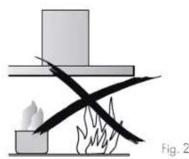
natural_image
Simple line drawing of a firecracker with smoke and flames, no text or symbols presentSAFETY WARNINGS – FOR THE INSTALLER
When installing the cooker hood, make sure you adhere to the minimum and maximum distances from the cooker hood base to the hob surface (refer to page 7).
Exhaust flue installation: The following rules must be strictly followed to obtain optimal air extraction.
- Keep exhaust flue short and straight.
- Do not reduce the size or restrict exhaust flue. Keep bends in the exhaust flue to a minimum.
- When using flexible flue always install duct with helix pulled taut to minimise pressure loss.
- Failure to observe these basic instructions will drastically reduce the performance and increase the noise levels of the cooker hood.
Exhaust air must not be discharged into a wall cavity, unless the cavity is designed for that purpose. The exhaust from the cooker hood must not be discharged into any heating flue, which may carry combustion products from other sources.
NOTE: Some installations may require the telescopic exhaust cover to be cut to length. Cut with sharp tin snips or a fine-tooth hack saw blade, taking care not to distort or dent the exhaust cover.
DESCRIPTION OF YOUR RANGEHOOD
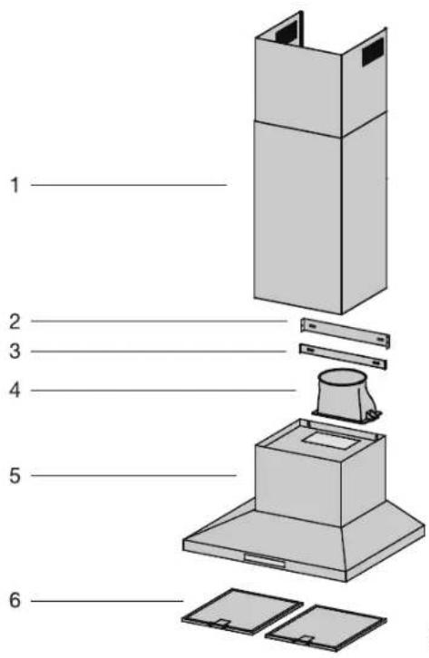
Fig. 3
Components list
Qty.
- Telescopic flue cover set 1
- Upper Flue mounting bracket 1
- Lower Flue mounting bracket 1
- Exhaust transition duct 1
- Main body and fan housing assembly....1
- Grease filter(WRC613SB) 2
- Grease filter(WRC913SB)....3
Technical specification
• Power supply: 240 V 50 Hz. Connects to 10 A power point
• Lights: 2 x 4 watt, 240 V LED
Additional items required for installation
- Fixings required to attach rangehood body and anti tilt points
• Fixings required to attach flue cover mounting brackets - Worm drive clamps, Duct tape or cable ties
- Ducting accessories
| MODEL | WRC613SB | WRC913SB |
| Height | 660 mm - 1,160 mm | 660 mm - 1,160 mm |
| Width | 600 mm | 900 mm |
| Depth | 500 mm | 500 mm |
| Max absorbed power | 338 W | 338 W |
| Lighting | 2 x 4W LED (GU10 fitting) | 2 x 4W LED (GU10 fitting) |
| Outlet diameter | 150 mm | 150 mm |
| Electrical connection | 220 - 240V, 50 Hz | 220 - 240V, 50 Hz |
The manufacturer reserves the right to make technical changes.
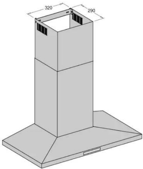
RANGEHOOD DIMENSIONS
WRC613SB
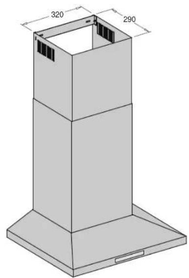
natural_image
3D technical drawing of a tall industrial chimney with base and top dimensions labeled (no text or symbols beyond measurements)WRC913SB
natural_image
Isometric technical drawing of a tall industrial chimney with base plate and top opening (no text or symbols)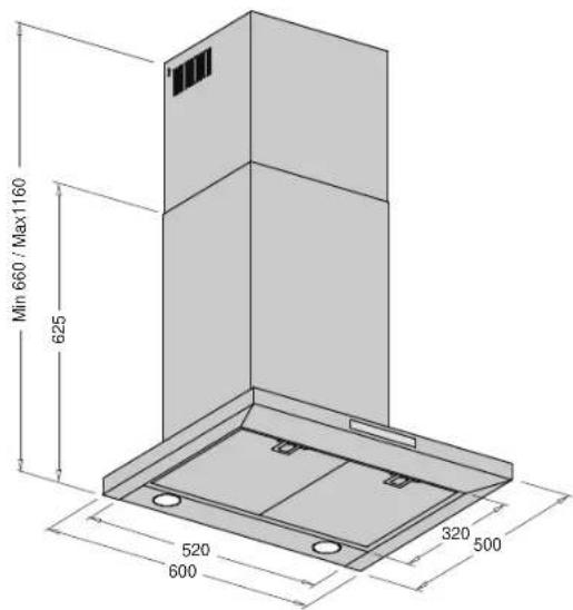
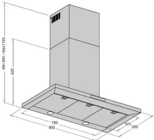
Fig. 4
INSTALLATION
PRE-INSTALLATION
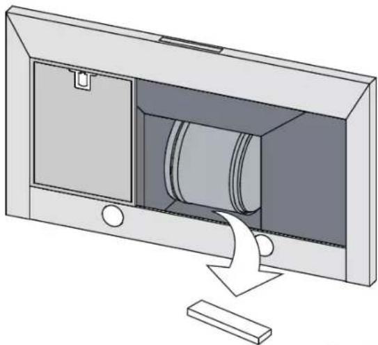
Before installing the cooker hood, peel off any protective plastic covering and remove polystyrene from inside behind the fan motor. See Fig. 5 below.
natural_image
Diagram of a cabinet or storage unit with a cylindrical component inserted, showing internal components and an arrow indicating direction (no text or symbols present)Fig. 5
LOCATION
The hood is to be mounted on the wall. When installed, the hood must be not less than 60cm above electric burners or 65cm above gas or mixed-fuel burners.
| Distance from hood base to top of hob | |
| hob type minimum* maximum | |
| gas 650mm 800mm | |
| electric 600mm 800mm | |
* If the instructions of the hob specify a greater distance than the minimum above, then that shall be the minimum height for installation.
INSTALLATION
- Using a spirit level mark a vertical centre line on the wall where the hood is to be positioned, and a horizontal line at the hood base position. (See Figure 4 for relevant model)
NOTE. The height of the underside of the hood body must be a minimum of 600mm* to a maximum height of 800mm.
* If the instructions of the hob specify a greater distance than the minimum above, then that shall be the minimum height for installation.
2. Mark the location for the flue cover wall mounting brackets and rangehood mounting points and anti-tilt fixing points above the hood base using the hood base as a reference point
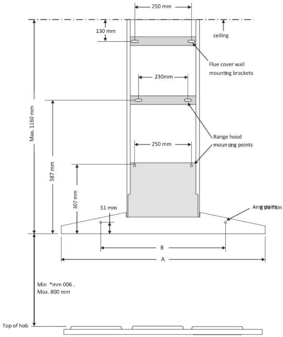
Fig. 6
| WRC613SBWRC913SB | ||
| A | 600 mm | 900 mm |
| B | 440 mm | 550 mm |
INSTALLATION
- Install flue cover wall mounting brackets with suitable fixings. Install suitable screws for rangehood mounting points (to support a total weight of 30kg) to the wall as marked (Fig. 7).
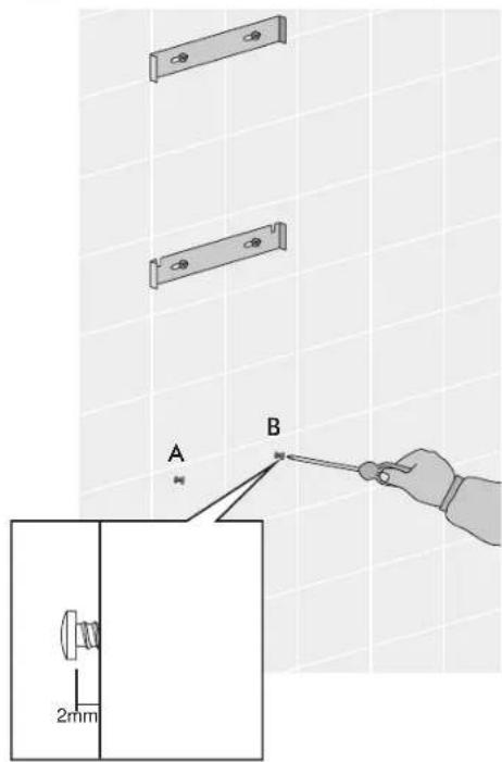
Fig. 7
- Fix exhaust transition duct using screws supplied (Fig. 8).
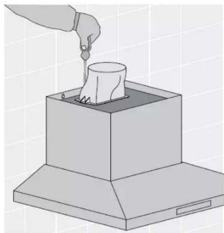
natural_image
Illustration of a hand pouring liquid into a container on an open box (no text or symbols)Fig. 8
- Hang the body hood on the mounting screws then secure at the anti-tilt locations as indicated in Fig. 6 & 7.
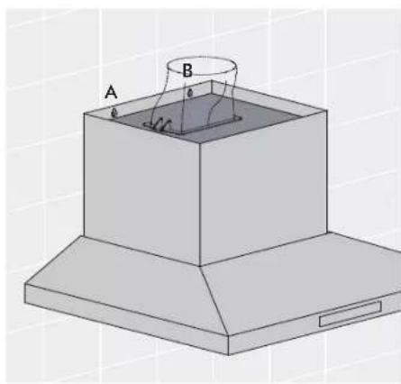
natural_image
3D diagram of a box with labeled points A and B, showing internal structure and no text or symbolsFig. 9
INSTALLATION
Depending on the preferred installation/ducting mode, follow step 6a or 6b below.
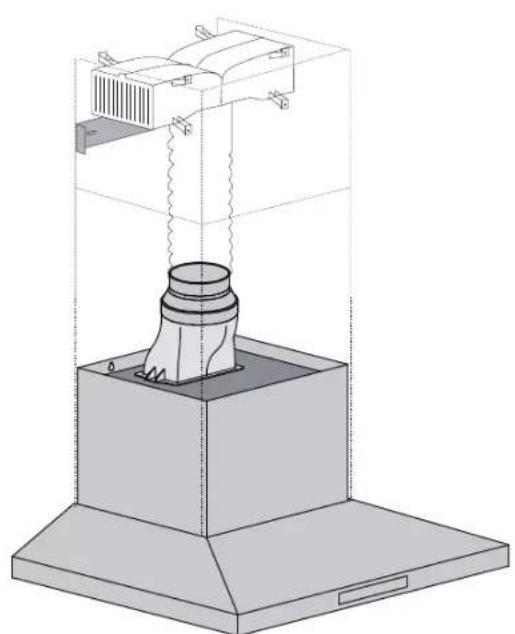
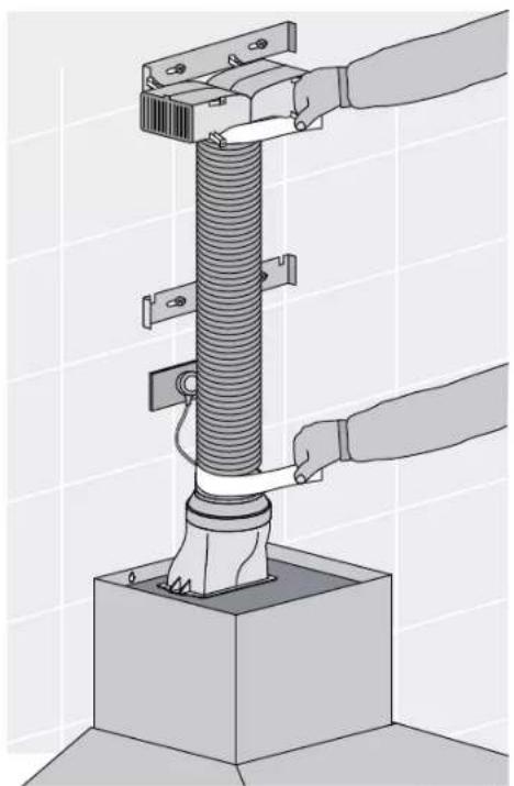
6a. Recirculating mode (Fig. 10). Using the centre line, secure the recirculating T-piece to the wall with suitable screws/fixings (optimal kit AR610RK). Install flexible pipe between T-piece and reducer. Use cable ties or suitable duct tape to secure flexible pipe to T-piece and reducer (Fig. 12).
NOTE: When installed in recirculating mode, it is recommended to use a carbon filter (included in recirculation kit AR610RK) to prevent odours being emitted back into the room.
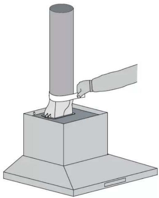
6b.Ducted mode (Fig 11.) Fit a 150mm diameter non combustible flue pipe. Continue the centre line to the ceiling. Fit flue pipe to the exhaust transition duct. Use cable ties or suitable duct tape to secure flue pipe to the transition duct.
NOTE: For ducted mode, extend the flue pipe through the roof to external 'roof cowl' to vent exhaust externally. Do not vent into the ceiling cavity.
NOTE: To ensure optimum performance of the rangehood, the use of rigid ducting (optional AR150F) is recommended. The use of bends should be avoided. Rigid flexible ducting is suitable, although loose flexible ducting is unacceptable. All ducting must be fire retardant.
natural_image
Illustration of a hand pressing a cylindrical object into a base, no text or symbols presentFig. 11
natural_image
Technical line drawing of a mechanical device with a base and housing (no text or symbols)Fig. 10
natural_image
Illustration of a hand operating a mechanical press or spring assembly mounted on a base (no text or symbols visible)Fig. 12
INSTALLATION
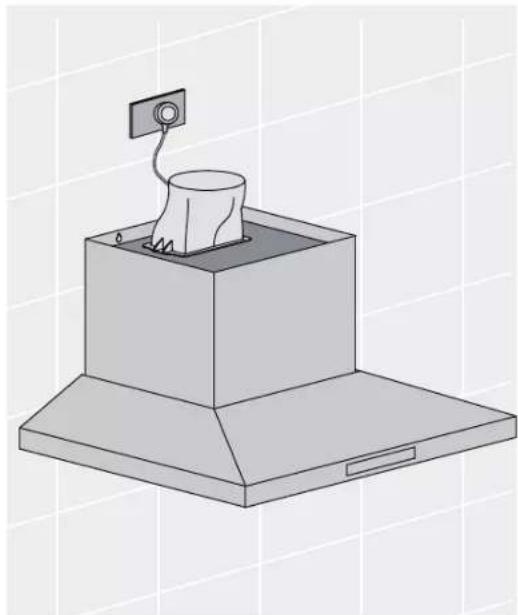
7. Electrical connection
Check that the installation complies with the standards of local building, gas and electrical authorities. Before connecting to the mains supply ensure that the mains voltage corresponds to the voltage on the rating plate inside the rangehood.
natural_image
Isometric illustration of a kitchen chimney with a mounted appliance (no text or symbols)Fig. 13
8. Installation of telescopic flue covers
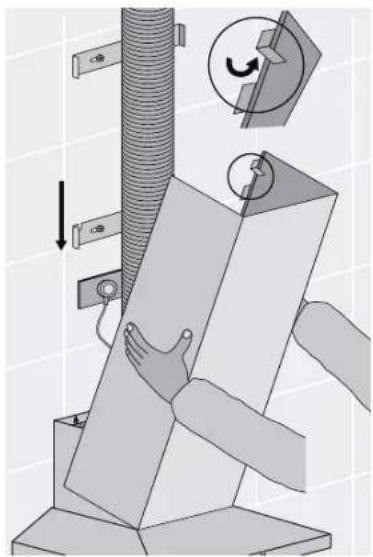
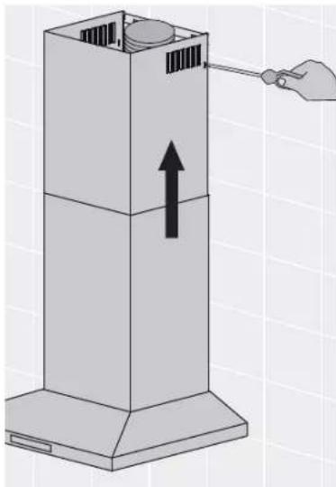
Separate the inner and outer flue covers, and carefully remove the protective coating from both. Carefully reassemble the upper and lower flue covers sections by sliding the inner into the outer flue cover. Carefully lower the assembled upper and lower flue covers onto the top of the rangehood body, and insert the flue cover into the rangehood body approximately 5mm.
9. Fix upper flue cover
Fix upper flue cover to the wall mounting bracket with screws supplied. Ensure that the upper section is extended.
natural_image
Mechanical assembly diagram showing a tool interacting with a cylindrical component and a paper sheet (no text or symbols present)Fig. 14
natural_image
Diagram of a vertical stacker with an upward arrow indicating force or movement, and a hand adjusting the load (no text or symbols present)Fig. 15

IMPORTANT!
Care must be taken to ensure the screws (supplied in accessories bag) are not cross threaded when attaching the upper flue cover. If installed in recirculating mode, insert the optional carbon filler (included in recirculation kit AR610RK). To complete the cooker hood installation, insert the three filters to the underside of the hood body. Place back edge of filter into position and push up front edge so that the filter clips into place.
Your Electrolux cooker hood is now ready to use.
CONTROL PANEL
- Best results are obtained by using a low speed for normal conditions and a high speed when odours are more concentrated.
- Turn the hood on for a few minutes before you start cooking.
- The hood should be left on for a minimum of 5 minutes after cooking or until all odours have dispersed.
- The control switches are located on the front panel of the unit. See Fig. 16 below.
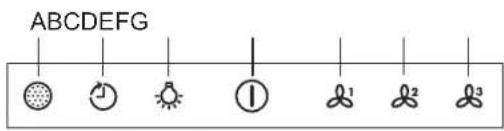
Fig. 16
A. Filter
- This is the indicator/switch to show when the filter needs to be cleaned.
- Once the filters are cleaned the "Filter" alert can be deactivated with a single touch.
B. Timer
Using the Timer
- At the end of cooking, if the timer is switched on, the rangehood will continue to run for an additional 5 to 15 minutes, depending on the selected fan speed.
- The fan speed is reduced in 5 minute increments until the rangehood turns it self OFF.
- If the fan speed is set on high, it will run for 5 minutes then reduce to medium for 5 minutes, then reduce to low for 5 minutes before finally turning it self OFF.
- This should ensure the removal of any odours that remain after cooking.
C. Lights
To switch Lights ON and OFF
- Touch the 'light' symbol to turn the lights ON.
- Touch 'light' symbol again to turn the lights OFF.
D. Power on/off
E. Fan speed 1 - light frying/boiling
F. Fan speed 2- frying/wok cooking/heavy boiling
G. Fan speed 3- grilling, intensive frying and wok cooking
CARE & MAINTENENCE
CAUTION
External surfaces are susceptible to scratches and abrasions, so please follow the cleaning instructions to ensure the best possible result is achieved without damage.
Cleaning the hood
- Clean the outside of the hood using a damp cloth and a solution of water and mild washing up liquid. Clean stainless steel surfaces using non-abrasive cleaning products that are specifically for use on stainless steel. To ensure the best results also use an even pressure and follow the grain of the stainless steel. Use of a soft cloth reduces the risk of scratching. If the cloth is wet ensure that a dry soft cloth is used to wipe down the surface and apply stainless steel protector to reduce the risk of any surface rust appearing.
- Never use corrosive, abrasive or flammable cleaning products or products containing bleach.
- Never insert pointed objects in the motor's protective grid.
- Only ever clean the switch panel and filter grill using a damp cloth and mild washing up liquid.
- It is extremely important to clean the unit and change the filters at the recommended intervals. Failure to do so will cause grease deposits that could cause a fire.
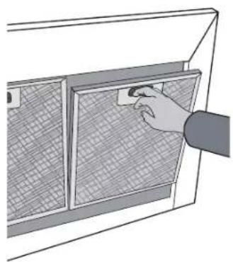
Removing the metal grease filters
- Push the grease filter towards the back of the unit and then pull it down and out.
natural_image
Illustration of a hand using a tool to clean or inspect a grid-patterned panel inside a cabinet (no text or symbols visible)NOTE. This product is fitted with a safety cutout device.
If the cooker hood is installed to close to the cooktop, flambe cooking, operating the cooktop without cooking utensils and blocked filters may activate the safety cutout device. If the hood stops during operation, correct the faults and allow time for the safety cutout device to reset, the cooker hood will then function correctly.
CARE & MAINTENENCE
Hand washing
Soak grease filters for about one hour in hot water with a grease-loosening cleaner, then rinse off thoroughly with hot water. Repeat the process if necessary. Refit the grease filters when they are dry.
Dishwasher
Place grease filters in the dishwasher. Select the most powerful washing program and highest temperature, at least 65°C. Repeat the process. Refit the grease filters when they are dry. When washing the metal grease filter in the dishwasher a slight discolouration of the filter can occur, this does not have any impact on it's performance.
NOTE: The metal grease filters must be removed and washed, either by hand or in the dishwasher, every four weeks.
- Clean the inner housing using warm water and grease loosing cleaner (never use caustic detergents, abrasive powders or brushes).
Charcoal filter
- The charcoal filter should only be used if you want to use the hood in the recirculation function.
- This filter cannot be cleaned or re-used and as a general rule, the activated charcoal filter should be changed once every four months.
Fitting the charcoal filter
Fit one charcoal filter on the left and one on the right so as to cover the plastic grids that protect the fan wheel.
• Always specify the hood model code number and serial number when ordering replacement filters. This information is shown on the registration plate located on the inside of this unit.
- Replacement charcoal filters can be ordered from your local Service Centre.
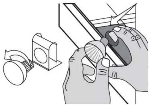
Changing the LED lamps
If LED lamps need replacing, they must be replaced by lamps as stated in the technical specifications.
natural_image
Illustration of hands using a tool to adjust a component, with a mechanical knob and a rotating knob nearby (no text or symbols)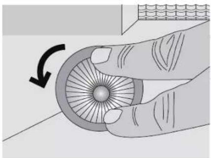
natural_image
Illustration of a hand holding a circular object with radial lines, showing a curved arrow indicating rotation (no text or symbols present)Ensure that the appliance is switched off before carrying out maintenance to avoid any possibility of electric shock.
TROUBLESHOOTING GUIDE
| REMEDYP R O B L E M | |
| The cooker hood will not start | Check that the hood is connected to an electrical supply |
| Check that a fan speed has been selected | |
| The cooker hood is not working | Check that the fan speed is set high enough for the task |
| The grease filters are clean | |
| The kitchen is adequately vented to allow the entry of fresh air | |
| If set up for recirculation, check that the charcoal filter is still effective | |
| If set up for extraction, check that the ducting and outlets are not blocked | |
| Do not operate cooktop without pots/pans | |
| Do not flambe under cooktop | |
| The cooker hood has switched off during operation | The safety cut-out device has been tripped – turn off the hob and wait for the device to reset. Check and clean filters. If the hood has been installed below the heights indicated in the installation instructions the motor will cut out frequently which will damage the hood. |
If you have completed all of the above checks and are still experiencing difficulty, please contact your local Electrolux Service Centre.
NOTE: This product is fitted with a safely cutout device.
- If the cooker hood is installed to close to the cooktop, flambe cooking, operating the cooktop without cooking utensils and blocked filters may activate the safety cutout device. If the hood stops during operation, correct the faults and allow time for the safety cutout device to reset, the cooker hood will then function correctly.
- Do not operate cooktop without pots/pans
- Do not flambe under cooktop
OPTIONAL DUCTING ACCESSORIES
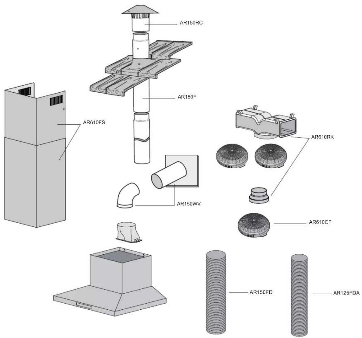
Part Numbers Description
| AR150RC | 150mm G/Bond Roof Cowl |
| AR150F | 150mm G/Bond Flue 1200mm |
| AR150VVV | 150mm Wall Vent & duct |
| AR610RK | Recirculating Kit (150-120mm reducer, T-piece & carbon filters |
| AR610CF | Replacement carbon filter |
| AR610FS | Stainless steel exhaust cover extension 1200mm |
| AR150FD | 150mm aluminum flexible duct |
| AR125FDA | 125mm aluminum flexible duct |
| 1438124 | 50mm wide aluminum tape (55m roll) |

Thinking is your Electrolux
Warranty
FOR SALES IN AUSTRALIA AND NEW ZEALAND APPLIANCE: RANGEHOOD
This document sets out the terms and conditions of the product warranties for Electrolux Appliances. It is an important document. Please keep it with your proof of purchase documents in a safe place for future reference should you require service for your Appliance.
- In this warranty
(a) 'acceptable quality' as referred to in clause 10 of this warranty has the same meaning referred to in the ACL;
(b) 'ACL' means Trade Practices Amendment (Australian Consumer Law) Act (No.2) 2010;
(c) 'Appliance' means any Electrolux product purchased by you accompanied by this document;
(d) 'ASC' means Electrolux' authorised serviced centres;
(e) 'Electrolux' means Electrolux Home Products Pty Ltd of 163 O'Riordan Street, Mascot, NSW 2020, ABN 51 004 762 341 in respect of Appliances purchased in Australia and Electrolux (NZ) Limited of 3-5 Niall Burgess Road, Mount Wellington, in respect of Appliances purchased in New Zealand;
(f) 'major failure' as referred to in clause 10 of this warranty has the same meaning referred to in the ACL and includes a situation when an Appliance cannot be repaired or it is uneconomic for Electrolux, at its discretion, to repair an Appliance during the Warranty Period;
(g) 'Warranty Period' means:
(i) where the Appliance is used for personal, domestic or household use (i.e. normal single family use) as set out in the instruction manual, the Appliance is warranted against manufacturing defects in Australia for 24 months and in New Zealand for 24 months, following the date of original purchase of the Appliance;
(ii) where the Appliance is used for commercial purposes (including being used to directly assist a business or where the Appliance is used in a multi-family communal or share type environment), the Appliance will then be warranted against manufacturing defects in Australia for 3 months and in New Zealand for 3 months, following the date of original purchase of the Appliance.
(h) 'you' means the purchaser of the Appliance not having purchased the Appliance for re-sale, and 'your' has a corresponding meaning.
- This warranty only applies to Appliances purchased and used in Australia or New Zealand and is in addition to (and does not exclude, restrict, or modify in any way) any non-excludable statutory warranties in Australia or New Zealand.
- During the Warranty Period Electrolux or its ASC will, at no extra charge if your Appliance is readily accessible for service, without special equipment and subject to these terms and conditions, repair or replace any parts which it considers to be defective. Electrolux or its ASC may use remanufactured parts to repair your Appliance. You agree that any replaced Appliances or parts become the property of Electrolux. This warranty does not apply to light globes, batteries, filters or similar perishable parts.
- Parts and Appliances not supplied by Electrolux are not covered by this warranty.
- You will bear the cost of transportation, travel and delivery of the Appliance to and from Electrolux or its ASC. If you reside outside of the service area, you will bear the cost of:
(a) travel of an authorised representative;
(b) transportation and delivery of the Appliance to and from Electrolux or its ASC,
In all instances, unless the Appliance is transported by Electrolux or an Electrolux authorised representative, the Appliance is transported at the owner's cost and risk while in transit to and from Electrolux or its ASC.
- Proof of purchase is required before you can make a claim under this warranty.
- You may not make a claim under this warranty unless the defect claimed is due to faulty or defective parts or workmanship. Electrolux is not liable in the following situations (which are not exhaustive):
(a) the Appliance is damaged by:
(i) accident
(ii) misuse or abuse, including failure to properly maintain or service
(iii) normal wear and tear
(iv) power surges, electrical storm damage or incorrect power supply
(v) incomplete or improper installation
(vi) incorrect, improper or inappropriate operation
(vii) insect or vermin infestation
(viii) failure to comply with any additional instructions supplied with the Appliance;
(b) the Appliance is modified without authority from Electrolux in writing;
(c) the Appliance's serial number or warranty seal has been removed or defaced;
(d) the Appliance was serviced or repaired by anyone other than Electrolux, an authorised repairer or ASC.
- This warranty, the contract to which it relates and the relationship between you and Electrolux are governed by the law applicable where the Appliance was purchased. Where the Appliance was purchased in New Zealand for business purposes the Consumer Guarantee Act does not apply.
- To the extent permitted by law, Electrolux excludes all warranties and liabilities (other than as contained in this document) including liability for any loss or damage whether direct or indirect arising from your purchase, use or non use of the Appliance.
- For Appliances and services provided by Electrolux in Australia, the Appliances come with a guarantee by Electrolux that cannot be excluded under the Australian Consumer Law. You are entitled to a replacement or refund for a major failure and for compensation for any other reasonably foreseeable loss or damage. You are also entitled to have the Appliance repaired or replaced if the Appliance fails to be of acceptable quality and the failure does not amount to a major failure. The benefits to you given by this warranty are in addition to your other rights and remedies under a law in relation to the Appliances or services to which the warranty relates.
- At all times during the Warranty Period, Electrolux shall, at its discretion, determine whether repair, replacement or refund will apply if an Appliance has a valid warranty claim applicable to it.
- For Appliances and services provided by Electrolux in New Zealand, the Appliances come with a guarantee by Electrolux pursuant to the provisions of the Consumer Guarantees Act, the Sale of Goods Act and the Fair Trading Act.
- To enquire about claiming under this warranty, please follow these steps: (a) carefully check the operating instructions, user manual and the terms of this warranty;
(b) have the model and serial number of the Appliance available;
(c) have the proof of purchase (eg an invoice) available;
(d) telephone the numbers shown below.
- You accept that if you make a warranty claim, Electrolux and its ASC may exchange information in relation to you to enable Electrolux to meet its obligations under this warranty.
Important Notice
Before calling for service, please ensure that the steps listed in point 13 above have been followed.
| FOR SERVICEor to find the address of your nearest state service centre in AustraliaPLEASE CALL 13 13 49For the cost of a local call (Australia only) | SERVICE AUSTRALIAElectroluxELECTROLUX HOME PRODUCTSwww.electrolux.com.au | FOR SPARE PARTSor to find the address of your nearest state spare parts centre in AustraliaPLEASE CALL 13 13 50For the cost of a local call (Australia only) |
| FOR SERVICEor to find the address of your nearest authorised service centre in New ZealandFREE CALL 0800 10 66 10(New Zealand only) | SERVICE NEW ZEALANDElectroluxELECTROLUX HOME PRODUCTSwww.electrolux.co.nz | FOR SPARE PARTSor to find the address of your nearest state spare parts centre in New ZealandFREE CALL 0800 10 66 20(New Zealand only) |
GRH_Warr_Apr11
For more information on all westinghouse appliances, or for dimension and installation information, call into your retailer, phone or email our customer care team or visit our website:
AUSTRALIA
phone: 1300 363 640
fax: 1800 350 067
email: customercare@electrolux.com.au
web: www.westinghouse.com.au
NEW ZEALAND
phone: 09 573 2384
fax: 0800 363 600
email: customercare@electrolux.co.nz
web: www.westinghouse.co.nz


Electrolux

SERVICE
TOP SERVICE
Top Service encompasses the after sales service provided by The Electrolux Group to consumers including delivery, home service and spare parts.
Westinghouse. We are part of the Electrolux family. Share more of our thinking at www.electrolux.com
Part number: 60901730 Issue B
© 2015 Electrolux Home Products Pty Ltd
ABN 51 004 762 341
Print code: WRC613SB_WRC913SB_CHJul15
- INSTALLATION AND USER MANUAL
- CONGRATULATIONS
- Conditions of use
- TIPS & INFORMATION
- UNPACKING
- ENVIRONMENTAL TIPS
- INFORMATION ON DISPOSAL FOR USERS
- CONTENTS
- IMPORTANT SAFETY INSTRUCTIONS
- CAUTION
- GENERAL WARNINGS
- ELECTRICAL CONNECTION
- SAFETY WARNINGS – FOR THE INSTALLER
- DESCRIPTION OF YOUR RANGEHOOD
- Components list
- Technical specification
- Additional items required for installation
- RANGEHOOD DIMENSIONS
- INSTALLATION
- PRE-INSTALLATION
- LOCATION
- Electrical connection
- Installation of telescopic flue covers
- Fix upper flue cover
- IMPORTANT!
- CONTROL PANEL
- Filter
- Timer
- Using the Timer
- Lights
- To switch Lights ON and OFF
- Power on/off
- CARE & MAINTENENCE
- Cleaning the hood
- Removing the metal grease filters
- Hand washing
- Dishwasher
- Charcoal filter
- Fitting the charcoal filter
- Changing the LED lamps
- TROUBLESHOOTING GUIDE
- Thinking is your Electrolux
- Warranty
- Important Notice
- AUSTRALIA
- NEW ZEALAND
- TOP SERVICE
Brand : WESTINGHOUSE
Model : WRC613SB
Category : Range hood