D-5.1300 - Hi-Fi System AudioControl - Free user manual and instructions
Find the device manual for free D-5.1300 AudioControl in PDF.


| Product Type | 5-Channel Power Amplifier |
| Power Output (RMS) | 130W per channel into 8 ohms |
| Total Power | 650W RMS |
| Frequency Response | 20 Hz - 20 kHz ±0.5 dB |
| Total Harmonic Distortion | < 0.05% |
| Signal-to-Noise Ratio | > 100 dB |
| Input Sensitivity | 1.2V |
| Input Impedance | 47k ohms |
| Speaker Impedance | 4-8 ohms |
| Damping Factor | > 200 |
| Protection Circuitry | Short circuit, thermal, overload |
| Trigger Input | 12V DC |
| Cooling | Convection with heat sink |
| Dimensions (W x D x H) | 17.0 x 13.5 x 4.0 inches |
| Weight | 28.5 lbs |
| Power Consumption | 1000W maximum |
| Speaker Terminals | Binding posts (5-way) |
| Gain Controls | Individual per channel |
| Bass Management | Built-in crossover (variable) |
| Remote Turn-On | Yes, via 12V trigger |
| Rack Mountable | Optional kit available |
| Maintenance | Clean with dry cloth; avoid liquids |
| Safety | Do not expose to moisture; ensure ventilation |
| Spare Parts and Repairability | Contact authorized service center; no user-serviceable parts |
| General Information | Designed for high-fidelity home audio systems |
Frequently Asked Questions - D-5.1300 AudioControl
User questions about D-5.1300 AudioControl
0 question about this device. Answer the ones you know or ask your own.
Ask a new question about this device
Download the instructions for your Hi-Fi System in PDF format for free! Find your manual D-5.1300 - AudioControl and take your electronic device back in hand. On this page are published all the documents necessary for the use of your device. D-5.1300 by AudioControl.
USER MANUAL D-5.1300 AudioControl
Features
• 5 high power amplifier channels
- 4 x 100 W @ 4 ohms + 1 x 300 W @ 4 ohms
- 4 x 200 W @ 2 ohms + 1 x 500 W @ 2 Ohms
• DM Smart DSP app included
- Input and Output RTA for precise and informed tuning
- GTO™ Signal Sense
- MILC™ Level Matching Technology (Patent pending)
- Option Port
- 8 Summable Speaker-Level Inputs for OEM integration
• Signal Delay
• 12 and 24 dB/octave crossovers
• 30 band equalizer
- Optional ACR-3 remote for preset recall and level control
• Cage free, Grade AA goodness
D-5.1300
High Power Multi Channel Amplifier with DSP Matrix Processor
Important Safety Instructions
- Read these instructions.
- Keep these instructions.
- Heed all warnings.
- Follow all instructions.
- Do not use this apparatus near water.
- Clean only with a dry cloth.
- Do not block any ventilation openings. Install in accordance with the manufacturer's instructions.
- Do not install near any heat sources such as mufflers, silencers, exhaust pipes, or other apparatus (including amplifiers) that produce heat.
- WARNING: Improper installation may lead to permanent injury or death. Installation of the apparatus must be done with great care by qualified personnel, to prevent damage to fuel lines, power, and other electrical wiring, hydraulic brake lines, and other systems, that might compromise vehicle safety.
- Provide +12V and Ground insulated wiring of between 4 and 0 AWG to ensure adequate current to the amplifier.
- Use rubber grommets to protect wiring whenever passing wires through metal openings or bulkheads.
- Only use attachments/accessories specified by the manufacturer.
-
Refer all servicing to qualified service personnel. Servicing is required when the apparatus has been damaged in any way, such as the power input terminals are damaged, liquid has been spilled or objects have fallen into the apparatus, the apparatus has been exposed to rain or moisture, does not operate normally, or has been dropped.
-
This apparatus shall not be exposed to dripping or splashing, and no object filled with liquids, shall be placed on the apparatus.
- Fuses shall be replaced only with the correct type and fuse value, and only when the apparatus is powered off.
- Exposure to high sound pressure levels may lead to permanent hearing loss. Take every precaution to protect your hearing.

The lightning flash with arrowhead symbol within an equilateral triangle is intended to alert the user to the presence of uninsulated "dangerous voltage" within the product's enclosure, that may be of sufficient magnitude to constitute a risk of electric shock to persons.

The exclamation point within an equilateral triangle is intended to alert the user of the presence of important operating and maintenance (servicing) instructions in the literature accompanying the appliance.
Caution: to reduce the risk of electric shock, do not disassemble the apparatus, other than to remove the top panel to access the controls.
There are no user-serviceable parts inside. Refer servicing to qualified personnel.

Recycling notice: If the time comes and this apparatus has fulfilled its destiny, do not throw it out into the trash. It has to be carefully recycled for the good of mankind, by a facility specially equipped for the safe recycling of electronic apparatii. Please contact your local or state recycling leaders for assistance in locating a suitable nearby recycling facility. Or, contact us and we might be able to repair it for you.
Features
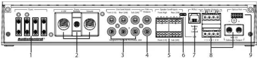
- Fuses 30A – Replace these fuses only with the exact same style and Ampere rating. Disconnect 12V power before changing or inspecting the fuses.
- Power Input Terminal +12V – The left screw terminal connects to the +12V battery binding post of the vehicle. Use good quality insulated wire, between 4 and 0 gauge.
Power Input Terminal Ground – The right screw terminal connects to a good ground connection on the vehicle. Use good quality insulated wire, between 4 and 0 gauge.
Remote Power Input Terminal – The middle screw terminal connects to the 12V remote trigger output of some head units. When the head unit is turned on, then the D-5.1300 will turn on. Alternatively, you can use the GTO ^™ feature of the D-5.1300 to turn the unit on. The GTO detects when the head unit is turned on via speaker level inputs 1/2 (front).
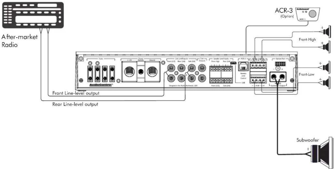
- RCA Analog Line-Level Inputs – The line-level output from the head unit or factory-installed radios can connect here, so the D-5.1300 will receive the line-level audio signals.
- RCA Analog Line-Level Outputs – These line-level analog outputs from the D-5.1300 connect to the line-level inputs of your power amplifiers and other equipment. The matrix capabilities of the D-5.1300 allow you to pick and choose the outputs from any combination of inputs, add crossovers and EQ as required.
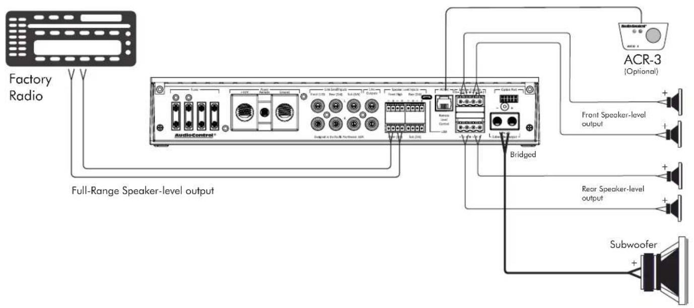
- Speaker-Level Inputs – The speaker-level output from amplifiers and factory installed radios can connect here, so the D-5.1300 will receive the audio signals this way and do its thing. Make sure that you follow the plus and minus polarity markings on the D-5.1300 and match it to the polarity of the speaker wiring. Speaker-level Inputs 1-2 have the GTO™ (great turn on) signal-sense circuit that will awaken the D-5.1300 when an input signal is present.
AudioControl®
Making Good Sound Great"
- USB Micro Connector – This connects to your computer's USB A port to configure the D-5.1300 with the control software.
- Remote Control Connector – This connects to the optional ACR-3 remote level control using a standard telephone cord.
- Speaker-Level Output Terminals – These screw terminals connect with speaker wire to your loudspeakers. Make sure that the average combined speaker impedance does not dip below 2 Ohms, or 4 Ohms in Bridged mode. Outputs 1 and 2 can be combined in Bridge mode to power a single speaker. Use the 1+ and 2- terminals only. Outputs 3/4 can also be combined in bridge mode, use the 3+/4- terminals only.
- Option Port – This port allows you to connect our optional AC-BT24 Bluetooth adapter, so you can stream audio into channels 7 and 8 from your Bluetooth-enabled devices. Or setup and control your D-5.1300 with the DM Smart app.
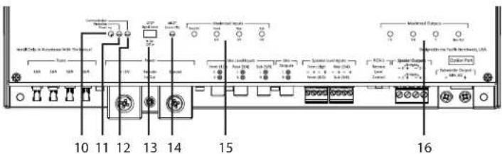
- Power LED – If you have connected your battery power, vehicle ground, and turn-on lead (or GTO ^™ signal sensing) correctly, then this light should be GREEN to indicate the power is ON. An internal blue glow will also emanate from the heatsink area to indicate that the power is ON. There are times when this blue glow will flash, such as during power-up, and when the protection circuits have detected a problem. See the table to the right.
- Protection LED – The D-5.1300 amplifier has built in diagnostic codes to tell you exactly what is going wrong should the amplifier detect a problem. Below is a list of diagnostic codes to help you.
If the protection LED should come on, read the red codes quickly before turning off the system and investigating. Note that the blue power codes mentioned in the table are for the internal blue glow from behind the heatsink area, and not the power LED which is green. If there is problem with the unit, the sensing circuit will shut down the unit to protect itself, and this protection LED will come on. For example, this might happen if the temperature within the unit is too high. Check there is good ventilation around the unit, and that the speaker wires are not short circuiting, and check that you are not running too low of a speaker impedance.
| Power (Blue) Codes | (These are the blue LEDs inside the unit) |
| Power Up | |
| Reset Boot | |
| Protection Activated | |
| Protection (Red) Codes | (This is the red Protection LED on the unit) |
| 1 Short | |
| 2 Repeated Short | |
| 3 Under Voltage | |
| 4 Over Voltage | |
| 5 DC Offset | |
| 6 Thermal Heatsink | |
| 7 Thermal Transformer |
-
Communications LED – This LED turns on when there is USB activity between the D-5.1300 and your computer during set up.
-
GTO™ Signal Sense – In the ON position, the D-5.1300 amplifier will turn on gracefully when it detects the source unit powering on with inputs 1 and 2, and it will turn off after a period of time when the audio signal fades away to silence. In some situations, factory installed audio systems may turn on or "wake up" due to convenience features like door chimes, alarms, and cell phone signals that trigger the source unit in the vehicle to come on. To prevent these from turning your audio system on unexpectedly, you can bypass the GTO™ circuit by moving the GTO™ switch to the OFF position and use a switched 12-volt signal connected to the Remote In terminal instead.
-
MILC™ Source Clip LED – With the MILC™ (Maximum Input Level Control) patent-pending level-setting circuit (on inputs 1-2 only), you are able to optimize the level of the incoming audio signal. While playing a 1khz test tone, increase the volume of the source unit until the Source Clip LED is illuminated, then back it down
until it is dimly lit or flickering on/off. Remember the number or position of your source's volume control, as this is your maximum undistorted volume level. If the LED comes on consistently during normal operation, the level of the audio signals should be lowered before they reach the input of the D-5.1300.
-
Maximized Input LEDs – These LEDs illuminate when a maximum audio signal is present on any of the analog audio inputs. During power-up, these LEDs and the output LEDs will turn on momentarily, one after the other. Turn down the levels if these LEDs are on a lot.
-
Maximized Output LEDs – These LEDs illuminate when there is maximum signal present on any of the analog audio outputs. Turn down the output levels if these LEDs are on a lot.
Power Connections
Head Unit
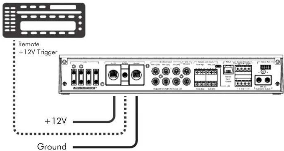
In this example, the head unit has a +12V trigger output that is connected to the D-5.1300 remote input terminal. When the head unit is turned on, it will turn on the D-5.1300.
Alternatively, the GTO ^™ signal sense feature can be used to gently turn on the D-5.1300 when an audio input signal is detected at inputs 1-2. (Then the connection to the D-5.1300's remote input terminal is not required.)
The +12V power wiring and Ground wiring should be between 4 and 0 AWG.
System #1: Using speaker-level inputs
AudioControl®
Making Good Sound Great"
System #2: Tri-amping
Quick Start Guide
Installation
We recommend mounting the D-5.1300 in the trunk/boot or cargo area of the vehicle. An alternative location would be under the front seat of your vehicle if there is enough room to install and also to reach the controls. When choosing a location, please keep these things in mind:
- Before you start, disconnect the +12V positive and negative cables from the battery in the vehicle to prevent any damage to the vehicle or the amplifier during the installation process.
- Pick a mounting location that will provide access to the controls and connections, provide adequate ventilation, and also protect the unit from heat, moisture, and dirt.
- The D-5.1300 needs to be securely mounted using the four mounting holes located in each corner.
- Before drilling any holes, take every precaution to prevent damage to fuel lines, power and other electrical wiring, hydraulic brake lines, and other systems, that might compromise vehicle safety.
- Always mount the unit as far from the antenna in the vehicle as possible, and away from the radio or any other RF sensitive electronics in the vehicle.
-
Use between 4 and 0 gauge insulated power cable to connect the +12V terminal of the D-5.1300 to the positive terminal of the vehicle battery.
-
The D-5.1300 has speaker-level inputs that are designed to accept amplified, speaker-level signals from a factory source unit or amplifier. You may need to refer to a factory service manual or wiring-harness schematic to determine which wires are the speaker wires for your system. If you are unsure which are the speaker wires, we recommend you look at the color of the speaker wires connected to the speakers and follow them back to the source. Connect the speaker wires to the D-5.1300 speaker-level input plugs using the correct polarity.
-
Line-level audio signals will generally come from your after-market radio, or if you are really getting the most out of your car audio system they may be coming from a really awesome product like the AudioControl LC6i (shameless plug). There are generally only two things to consider when using the line-level RCA inputs:
-
Use good shielded or twisted pair RCA cables.
-
Run your RCA cables at least 18" away from power and speaker cables to avoid picking up radiated noise in your system.
ACR-3 Dash Control Option
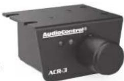
The optional AudioControl ACR-3 dash control is a dual-function remote for your D-5.1300. It may be mounted under the dash using its own bracket, or through a custom hole in the dash. The endless knob should be within reach of the driver, and in a spot where the two LEDs are plainly visible. Disconnect the vehicle battery +12V and Ground connections before installation.
-
When the left (BLUE) LED is on, turn the remote knob clockwise to turn the level up, and counterclockwise to turn it down.
-
To recall a memory preset with the ACR-3, press the knob in to switch from blue mode (volume control) to RED mode (preset recall). If, within two seconds, you turn the knob clockwise one click, it will recall one preset higher than you are currently operating. If, within two seconds, you turn the knob counter-clockwise, it will recall one preset lower than you are currently operating (for example, to change from Memory 2 to Memory 1).
Top Lid Removal
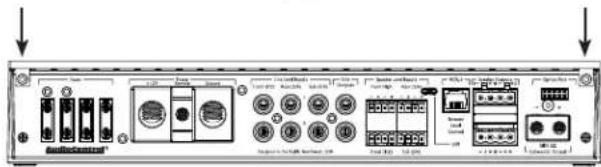
The top lid must be removed to gain access to the controls, and then put back on again to protect the controls from dust bunnies.
Removal Procedure
- Locate the two screws that hold the straight edge of the lid onto the connector side of the amplifier.
-
Use the supplied hex key to loosen both screws just enough until this edge of the lid can lift freely up just a little. (There is no need to remove the screws all the way, in case you lose them.)
-
Slide the lid toward the heatsink fins just a tad, before further lifting the straight edge of the lid about 2", then disengage the remaining two points of contact (under the wavy edge).
-
Place the lid in a safe and handy place, ready for the time when you have finished adjusting the controls to your immense satisfaction, and just before Parker brings tea and sandwiches.
Quick Start
Before you start, please take a moment to visit our knowledge base: www.audiocontrol.com/knowledge-base. It will help you with a plethora of sound advice, and help set the mood for the installation.
- The following details give a brief overview of the steps required to install the D-5.1300 in your system. The steps below are explained in more detail throughout the on-line manual.
- Undo the +12V and Ground connections to the car battery before making any connections to the D-5.1300.
- When making connections, designate red RCA plugs as right, and designate white, black, or gray plugs as left.
- Use quality interconnect cables. We know from experience that really cheap cables can cause a multitude of problems.
- Connect the +12V input terminal of the unit to the +12V terminal of the vehicle battery.
- Connect the Ground terminal of the unit to the negative terminal of the vehicle battery.
- Connect the remote power terminal of the unit to the remote turn-on switch of your source unit. Alternatively, you can skip this connection and use the GTO ^™ Signal sensing on inputs 1-2.
- Connect your audio inputs to the unit – either speaker-level or line-level RCA.
-
Run the optional ACR-3 remote to the front of the vehicle to adjust the level on the fly.
-
Note that the following initial setting up is carefully done with no speakers connected, to help prevent tweeter damage (for example) during the D-5.1300 setup.
- When you are satisfied that all is looking good and correct, reconnect the vehicle battery. Make sure that any external amplifiers are off.
- Install the control application onto your computer. (You can find this at www.audiocontrol.com)
- Connect the computer to the unit using the USB micro connection, and run the application. The unit will be recognized and you can enter an initial password (1234) that you can customize later.
- Use the application to adjust every aspect of the D-5.1300 operation until you have the system just right. Set up the optional remote control to adjust the levels you want.
- With the computer removed, the D-5.1300 will now operate just as you have it set up.
- Turn off the power, and connect your loudspeakers to the D-5.1300 or your external amplifiers.
- Turn on the system and play the source at minimum volume to begin with, then bring up the levels slowly.
- Enjoy the drive!
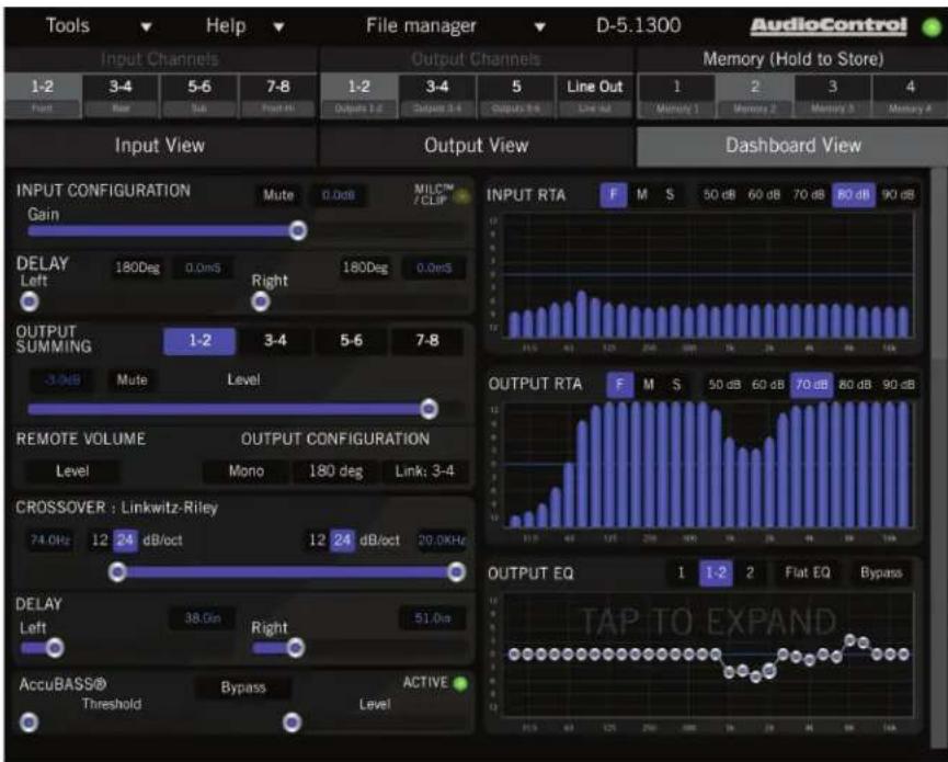
The Display
The display has three main sections: Input View, Output View, and Dashboard View, in addition to the top menu bar (File, Tools, Help) and the Memory (1, 2, 3, 4) section.
For more details of the software application, please take a look at the on-line owner's manual.
Input View
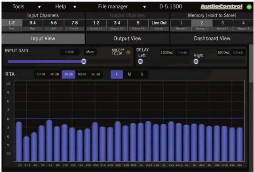
This display allows you to set the input gains, polarities and delays. The goal of the Input View display is to get all of the signals arriving to the D-5.1300 evenly balanced in level, and time-aligned so that they can be summed as desired later. The integrated Real Time Analyzer (RTA) is helpful in achieving this objective.
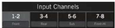
- Select an input pair from this row, then the parameters shown will be for this input pair.
bar
| Channel | Output Value | | :--- | :--- | | Input GAIN 0.0dB | 0.0 dB | | MILETM / CLIP | 70 dB | | DELAY Left 180Deg | 90 dB | | Right 180Deg | 0.0mS | | RTA 50 dB | 60 dB | | RTA 70 dB | 80 dB | | RTA 90 dB | 90 dB | | RTA F | 3 M | | RTA S | 12 |AudioControl® Making Good Sound Great™
Output View
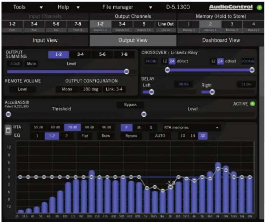
This is where you will spend the majority of your tuning time, as it is where you will set routing and summing, output levels, crossovers, EQ and AccuBASS® settings. The D-5.1300 is exceptionally flexible, and can be configured to use any output in any bandwidth or source and match the needs of the installation.
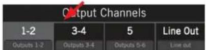
- Select an output from this list, and it will be highlighted in glorious living gray. Then all the parameters shown are for this output pair.
bar_line
| Parameter | Value | | --------- | ----- | | CROSOVER : Linkwitz-Riley | 74.0Hz | | DETA | 12 dB/oct | | DELAY | 38.0in | | Bypass | -3.8 | | Threshold | | | Active | | | RTS | 50 dB | | EQ | 1 | | Format | 1:2 | | Format Ratio | 2 | | Format Power Ratio | Flat | | Format Output Ratio | Draw | | Format Output Power Ratio | Bypass | | Output Summing | -3.0dB Mute | | Output Configuration | Mono 180 deg Link: 3-4 | | Input View | Output View | | Input View | Output View | | Input View | Output View | | Input View | Output View | | Output View | Output View | | Output View | Output View | | Output View | Output View | | Output View | Output View | | Output View | Output View | | Output View | Output View | | Output View | Output View | | Output View | Output View | | Output View | Output View | | Output View | Output View | | Output View | Output View | | Output View | Output View | | Output View | Output View | | Output View | Output View | | Output View [Output] | 1-2, 3-4, 5-6, 7-8, 1-2, 3-4, 5, Line Out, Memory 1, Memory 2, Memory 3, Memory 4, Memory 5, Memory 6, Memory 7, Memory 8, Memory 9, Memory 10, Memory 11, Memory 12, Memory 13, Memory 14, Memory 15, Memory 16, Memory 17, Memory 18, Memory 19, Memory 20, Memory 21, Memory 22, Memory 23, Memory 24, Memory 25, Memory 26, Memory 27, Memory 28, Memory 29, Memory 30, Memory 31, Memory 32, Memory 33, Memory 34, Memory 35, Memory 36, Memory 37, Memory 38, Memory 39, Memory 40, Memory 41, Memory 42, Memory 43, Memory 44, Memory 45, Memory 46, Memory 47, Memory 48, Memory 49, Memory 50, Memory 51, Memory 52, Memory 53, Memory 54, Memory 55, Memory 56, Memory 57, Memory 58, Memory 59, Memory 60, Memory 61, Memory 62, Memory 63, Memory 64, Memory 65, Memory 66, Memory 67, Memory 68, Memory 69, Memory 70, Memory 71, Memory 72, Memory 73, Memory 74, Memory 75, Memory 76, Memory 77, Memory 78, Memory 79, Memory 80, Memory 81, Memory 82, Memory 83, Memory 84, Memory 85, Memory 86, Memory 87, Memory 88, Memory 89, Memory 90, Memory 91, Memory 92, Memory 93, Memory 94, Memory 95, Memory 96, Memory 97, Memory 98, Memory 99, Memory100 |Dashboard View
This display allows you to conveniently see the settings of any one input and any one output simultaneously. All of the controls work the same as the Input View and Output View.
AudioControl®
Making Good Sound Great™
Specifications
All specifications are measured at 14.4 VDC (standard automotive voltage). As technology advances, AudioControl reserves the right to continuously change our specifications, like our Pacific Northwest weather, although we are working on changing that as well.
D-5.1300
Power Output....4 x 100 Watts @ 4 Ohm
2 x 400 Watts @ Bridged 4 Ohm*
1 x 300 Watts @ 4 Ohm
4 x 200 Watts @ 2 Ohm
1 x 500 Watts @ 2 Ohm
Frequency Response 20 Hz - 22 kHz
S/N Ratio 102 dBA, ref 200 Watts @ 2 Ohm
THD+N ....<0.1%
Bass Processing ....AccuBASS® Restoration
AccuBASS® Patent # 9,225,305
Power / Ground Wire Gauge......between 4 and 0 AWG
Fuse Rating 4 x 30 amps
Speaker-Level Inputs.... 8 x, summable, 40 V max
Line-Level Inputs....6 x, balanced RCA, 6 V max
Line-Level Outputs....2 x, balanced RCA, 6 V max
Weight 7.2 lbs
Dimensions....12.00"W x 7.95"D x 2.10"H
Hand-grown and ecologically harvested from the wooded slopes of Mountlake Terrace, Washington.
©2020 AudioControl. All rights reserved.
*Bridged rating on 5th channel goes unspecified due to those pesky laws of physics
Brand : AudioControl
Model : D-5.1300
Category : Hi-Fi System