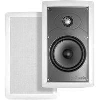
SC65 - Loudspeaker POLK - Free user manual and instructions
Find the device manual for free SC65 POLK in PDF.


| Product Type | 2-way bookshelf speaker |
| Brand | Polk Audio |
| Model | SC65 |
| Driver Configuration | 6.5-inch woofer, 1-inch tweeter |
| Dimensions (H x W x D) | 8.5 x 5.5 x 6 inches |
| Weight | 5 lbs |
| Power Handling (RMS) | 50-100 Watts |
| Impedance | 8 Ohms |
| Frequency Response | 50 Hz - 20 kHz |
| Sensitivity | 88 dB |
| Recommended Amplifier Power | 20-100 Watts per channel |
| Enclosure Type | Bass reflex (ported) |
| Wiring | Spring clip terminals |
| Placement | Bookshelf or stand |
| Care and Cleaning | Wipe with dry cloth; avoid moisture |
| Safety | Keep away from water and heat sources |
| Spare Parts Availability | Contact Polk customer service |
| Repairability | Serviceable by authorized technician |
| Warranty | 5 years limited |
| Included Accessories | Speaker grille, user manual |
Frequently Asked Questions - SC65 POLK
User questions about SC65 POLK
0 question about this device. Answer the ones you know or ask your own.
Ask a new question about this device
Download the instructions for your Loudspeaker in PDF format for free! Find your manual SC65 - POLK and take your electronic device back in hand. On this page are published all the documents necessary for the use of your device. SC65 by POLK.
USER MANUAL SC65 POLK
Installing Your In-Wall or In-Ceiling Speakers

Section 1: Introduction To Installing In-Wall or In-Ceiling Polk Audio Speakers
Installing your new Polk Audio in-ceiling or in-wall speakers is relatively easy to accomplish for even the most hesitant do-it-yourselfer. This Guide will take you through the process step by step. Installing your new Polk speakers can be very rewarding, and they look and sound great too.
At first, many are intimidated thinking about attempting this on their own. Thinking about cutting into your drywall should not be a barrier to doing this yourself. Sheet rock or dry wall is by design a very forgiving building material. We suggest that you choose walls or ceilings that are not covered with wallpaper or have a faux finish. Since, in some cases the need to cut into a wall to install the cabling is necessary, and that hole will need to be patched and painted, matching the patterns on some wall papers, and harmonizing a faux finish can be difficult. But if you consider yourself to be a wiz at wallpaper and/or paint repair, go for it!
Here is a quick "personal test" to see if you're up for doing this yourself:
Are you familiar the following tools:
- Stud finder
- Tape measure
- Utility Knife
• Power drill and driver - Sheet rock saw
- Putty knife
- Wire fish tape
- Wire stripers
- Full frequency 50 nanosecond vector scope and are confident about troubleshooting any frequency scatter between 5 and 2.35 gig?
If you at least have a working knowledge of these basic tools then see below to gain confidence.
Have you ever run cabling for any of the following:
- Telephones
- Computer network
- Printer cable
- Track lighting
• Automatic sprinklers
• Outdoor or indoor lighting
• Cable or satellite television - A security system
And do you feel comfortable with any of the following:
• Repairing a hole in sheetrock or drywall
- Installing "on wall" shelving
• Installing baseboards or crown molding
If you answered yes to any of these and are familiar with the tools listed, we're confident that you are capable of installing Polk speakers.
Safety and Code Review
- Use material and speaker cabling that conforms to your community and state building codes—your retailer or home center service personal will know if these are unique and which material to use.
- Use caution when standing on a ladder.
• Always use eye protection. - When in a crawl space, attic or unfinished basement be sure to light the space safely.
- Take your time.
- When drilling into walls or ceilings shut of power to that area of the house.
- When drilling through a fire block or any fire barrier, after installing the wire, be sure to fill the hole with a comparable fire retardant material (available in small quantities at any home improvement center in a convenient aerosol can).
- When cutting or stripping wires, or using sharp blades—slow down, make sure you have enough light, and always cut or slice in a motion away from your body.
Photos and description of the Tools
Sheet rock saw
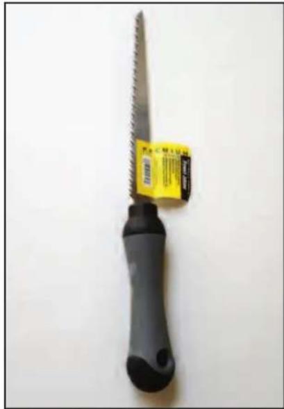
Fish tape to help install wire into existing walls

Battery powered hand held drill and driver (shown with magnetic driver extension)

Stiff Putty blade
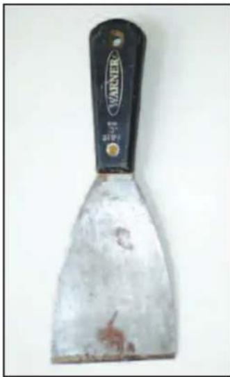
Tape measure, utility knife and wire stripper

Section 2: Polk Audio In-Wall and In-Ceiling Speaker Installation Guide
Materials and Preparation
Before cutting into your walls to install your new Polk Audio speakers, gather up all the tools and materials needed to complete the project.
Speaker cable: the audio signals are going to run on the cables you install. Here are some things to know and options to think through:
- Cable vs. wire: A cable utilizes more than one conductor, a wire uses just one conductor-even if the wire is "stranded" or has several bare wires together-in all basic speaker applications you will need a minimum of 2 conductors, thus the term cable is used here instead of "wire".
2) Be certain that you have enough speaker cable—it is always a good idea to cut each run of cable 3' to 6' longer than needed. The length of your cable run will determine the gauge of wire needed. The term "gauge" refers to the size of the cross section of the wire, (the lower the gauge number, the larger the wire is in diameter).
The following is a good general guide for wire sizing:
a. Runs under 100' (33m) use 14 or 16 gauge cable.
b. Runs over 100' use 12 gauge cable.

3) Your audio retailer can recommend the brand and type of cable that will work best for your application. Some things your retailer will need to know to make an appropriate recommendation:
a. Overall length of the cable run
b. The room application (is this for your home theater or for background music in your bathroom?)
c. The local building codes
4) We recommend utilizing a stranded cable that is manufactured specifically for speakers which wraps the conductors in one jacket and are commonly called 16/2:
16/2 = meaning that the conductor size is 16 gauge with 2 conductors.
5) Plan where you plan to run the cable. If you want to run cable under a carpet or on a wall then we recommend "flat" style cable. If you are going to run the cable entirely inside of walls or through attics or crawl spaces, "round" cable will do and will save you some money. Any of your choices will work and but final leg of you cable route will need to be run in the wall.
Planning Where to Run the Cable
The planning process starts with some basic layout decisions and the type of application chosen. Here are three basic types of systems:
Scenario 1
Home Theater: In this example the three front speakers (front left, front center, and front right) are traditional free-standing speakers while the rear surround speakers are in-wall (or in-ceiling) speakers. This situation will require running cables to the rear locations from the surround receiver.
Floor plan view:
![graph TD A["Television Display and component entertainment cabinet"] --> B["Surround speakers"] B --> C["Top Speaker"] C --> D["Bottom Speaker"]](/content/2026/05/1054142/images/d8ec3ad2da63a6679df9c2eb9560d9afde495e854a9a4a929a473b5c22561856.jpg)
Scenario 2
Wall-mounted flat-screen TV with in-wall speakers in the front:
![graph TD A["Speaker 1"] --> B["Sunset"] C["Speaker 2"] --> B D["Speaker 3"] --> B B --> E["Red Arrow to Speaker 1"] B --> F["Red Arrow to Speaker 2"] B --> G["Red Arrow to Speaker 3"]](/content/2026/05/1054142/images/4e422e174658625c84c3995ecf899b493ee8657f21b0f62a7b5a7750e3ed5797.jpg)
In this case the cabling would be run from the surround receiver to the speakers.
Scenario 3
The speakers will be installed in the ceiling for music in the kitchen utilizing a volume control on the wall to adjust the volume to the speakers. In this room there are three cable runs, the first is two sets of speaker cables that run from the amplifier or receiver to the volume control on the wall, then another run of speaker cables to each speaker.
![graph TD A["From amplifier to Volume control"] --> B["Speaker"] B --> C["Volume control"] C --> D["Speaker"] D --> E["Volume control"] style A fill:#f9f,stroke:#333 style B fill:#ccf,stroke:#333 style C fill:#cfc,stroke:#333 style D fill:#fcc,stroke:#333 style E fill:#ffc,stroke:#333](/content/2026/05/1054142/images/fad5ad7dfed0aac903634c650e89571ce6a411cd27aa88b2e46c07bdd56da40d.jpg)
Volume control with face plate:

Rear view of a typical volume control:
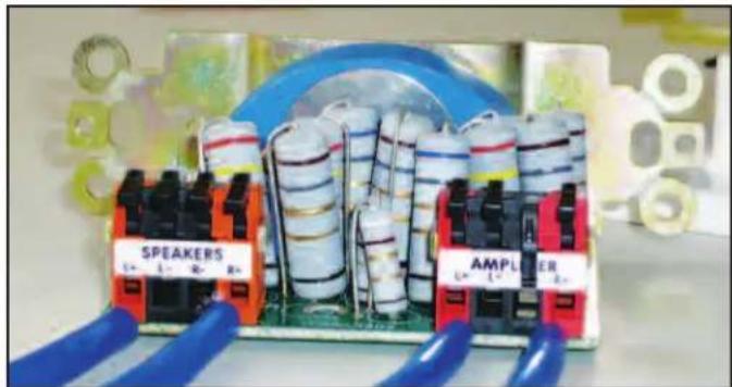
input from amplifier
Planning Your Cable Routes
NOTE: In a stereo installation the cable length to each speaker within a room should be about the same to avoid volume or time shifts from channel to channel. In home theater installations the cable lengths for Front Left, Center and Right channels should be about the same. The cable lengths to the rear speakers will in most cases be longer than those to the front three speakers and that's OK.
Whenever possible take advantage of attic and crawl spaces as it is much easier to run cables through them than walls.
Section 3: Checking For Obstacles Before Installation
Speaker placement research: Once you have a good idea about where you want to install your new Polk speakers, we suggest you check out the space just to make sure there is enough room for the speakers. When your home was built the contractors ran gas piping, air ducts, drain and water pipes, electrical, phone and data cables. Also check that the placement of the speakers will be symmetrical once you have established where the joists and studs are:
Note the location of all studs using your stud sensor.

Use a stud finder to locate structural members inside the walls and ceiling.
Then:
Drill a small 1/2" hole in the sheet rock then using a stiff wire or bent coat hanger "feel" for any obstructions.
Be sure to check the locations for all the speakers, if you discover that one location won't work and you have to go to an alternate location that may affect where you want to place the others.

Drill a small exploratory hole

Bend a stiff wire at a right angle

Use the wire to "feel" for wires, pipes and obstructions in the wall. If you feel an obstruction, wire or pipe with the wire probe, choose another speaker location. Some obstructions could include electrical wiring, drain, hot, and cold water piping. If you feel no obstructions, now you can cut the opening for the speaker.
Once you have determined the locations for your Polk speakers tape the supplied templates to the wall or ceiling.

The use a pencil and trace the edge of the template:
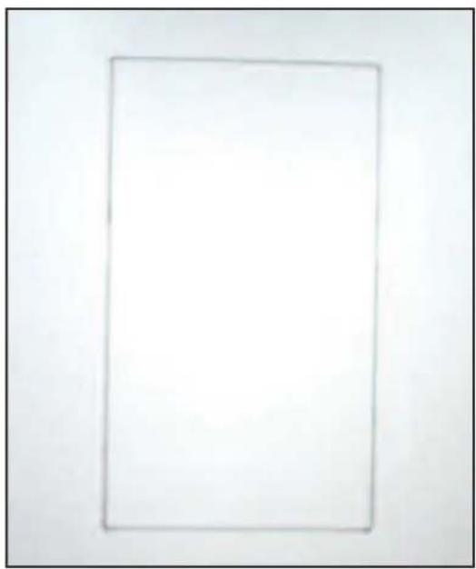
Section 4: Installing Polk Speakers: Cutting Drywall and Running Speaker Cables
This section covers cutting into the walls and installing the cables.
Supplies
Now is the time to gather your supplies:
1) Speakers
2) Speaker cable
3) Cleaning material
4) Tools
5) Wall plates
6) Connectors
Cutting Sheet Rock
Cutting sheetrock is a deal-breaker for some people and you may be one of them. At this point you may make the decision to bring in a professional to pull the cable and install the speakers. Polk Audio can recommend a professional installation company, call (800) 377-7655 during normal east coast business hours. But cutting sheetrock is not that difficult, and in the long run you'll enjoy your built-in speakers even more knowing that you installed them yourself.
Note: There are many "Roto" type power tools on the market and you may be tempted to use them to impress your audience – but they are no faster than hand saws and increase dust by a factor of 10! Hand saws also have the advantage of giving you more "feel" making it less likely that you'll saw through a water pipe.
Sheetrock saws have a pointed tip that make it easy to punch into the sheetrock to start the cut.

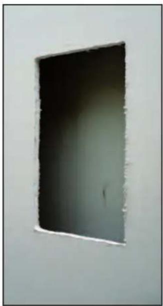
Some obstructions could include electrical wiring, drain, hot, and cold water piping:
Don't cut these things. Bad things will happen.
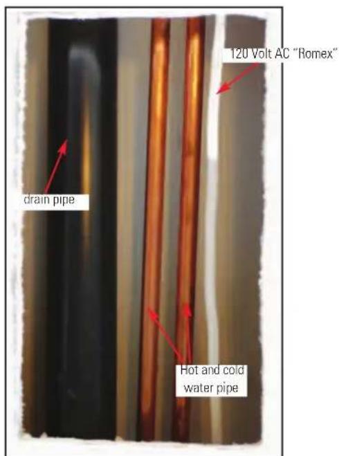
Installing the speaker cables:
A few rules, some general guidelines and a couple of tips will help this process go smoothly.
The Universal Building Code or UBC, and most all local codes have some restrictions on how large of a hole you drill in structural members, for the vast majority of installations this will not be an issue because of the small holes - you only have to pull a cable or two.
Here are the guidelines:
When working with studs: studs support your roof and partition off the various rooms in the home. Standard stud sizing is as follows:
2 x 4 measures 1 1/2" by 3 1/2"
2 x 6 measures 1 1/2" by 5 1/2"
2 x 8 measures 1 1/2" by 7 1/2"
Standard cross section of a modern 2 x 4

Codes usually recognize walls in two categories: "load bearing" and "non-load bearing".


Studs in load bearing walls have these restrictions:
Holes must be LESS then 40% the width of the stud Notches must NOT exceed 25% the width of the stud
When unsure if the wall you're planning on using is a load bearing wall or not then just treat it as if it were "Load Bearing".
Running speaker cable with alternating current or AC lines:
The national code restricts the use of common holes for both. Also for performance reasons try to separate your speaker cabling from the AC lines with as much distance as practical:

WRONG!

The above photos show the wrong way to run your speaker cables and the photo to the right show the correct way.
When running speaker cables separate them from AC wiring and when crossing the AC wires cross them at 90 degrees:

RIGHT

When bending the speaker cables use a gentle or gradual arch:

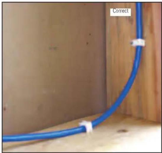

Wrong

And when using tie wraps or staples be careful to not "over tighten" or "over fasten" the cables: These cables so mashed and attached to these studs that they now rate as part of the structural mass helping hold the house up!
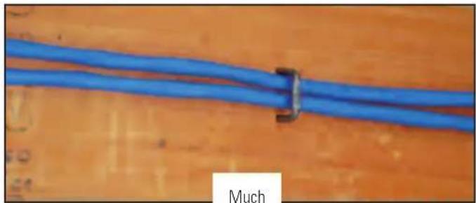
Much Better
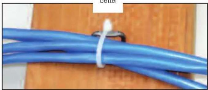
Leave a bit of room, these cables are not going anywhere, and we have not damaged the integrity of the conductors—Elvis is pleased that his music is not distorted.
Tips to running cable in existing walls
Vertical runs: In a 2 story home where you want to run cabling between floors to some ceiling speakers:

Using your stud finder determine which way the joists or structural members above your ceiling run. Then notch out a small section of the drywall on the wall and ceiling as shown:


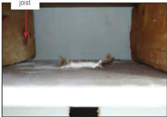
View from inside the ceiling space
Carefully drill through the top plate as shown to create a cable channel:

When attaching speaker cabling to the pull or fish tap—overlap the cable through the "paper-clip" on the end of the fish tape. Start with the fish-tape end and cover the whole connection with at least two layers of electrical tape as shown:

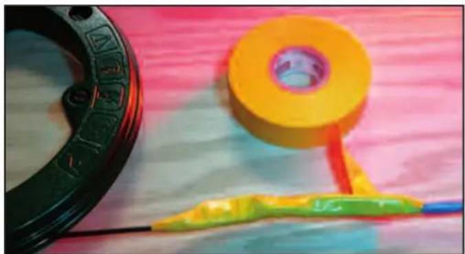
Thread the pull tape from the top notch through the wall to the opening, attach the speaker wire and pull (gently) up through the wall.


Thread the cable through the top plate (use the fish-tape if needed). Fish the tape from your speaker opening back through the wall/ceiling notch, attach the cable and pull over to the speaker opening.


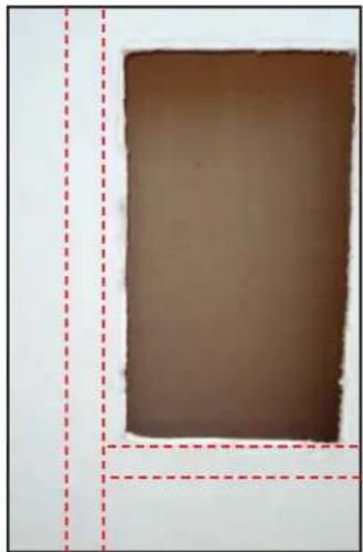

When you find a fire-block in between the studs it is possible to drill through using the speaker hole to get your drill into the wall:
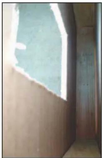

Horizontal runs
Running speaker cabling across a room may seem difficult—one good idea is to utilize the base board molding.
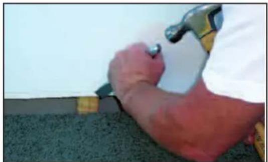
First use a utility knife and score the top edge of the base molding to separate the paint on the dry wall and the paint on the molding then using a stiff putty blade gently pry the molding outward as shown:


The image below is a photo of a cross section of a typical wall:
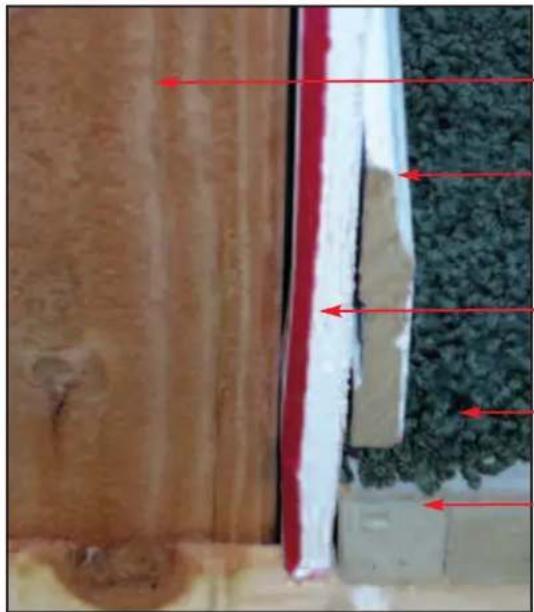
wall stud
base molding
sheet rock or dry wall
carpet & pad
sub floor
The idea here is to utilize the space behind the base molding for our horizontal cable runs, if needed notch the studs:

Now you can install the cable:

Replace the molding, and touch up with paint, now you are ready to install your new Polk speakers!
Section 5: Speaker Installation and Hook Up
By now you have the speaker cables in the walls and the holes cut for your new Polk speakers.
Start by dry-fitting your speakers into the openings. The speaker should slide into the hole with approximately 1/8" wiggle room—this leaves enough space to "straighten" the speaker to the walls and ceiling. In most cases walls are not exactly "true" or squared to each other.
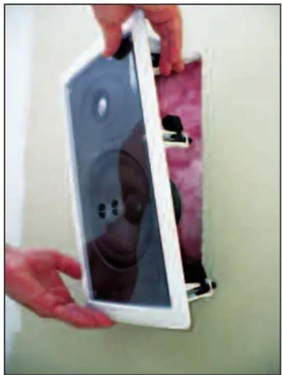

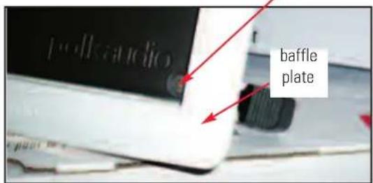
Our speakers utilize a unique "rotating cam" that presses the front baffle casing to the wall and allows for easy installation from the front side of the speaker.
Phillips head screw, accessed from the front of the speaker
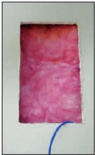
For additional acoustic performance install some insulation into the wall cavity (be sure to place the same amount behind each speaker).

Strip your speaker cables back about 3/4", and insert the pair into the input on the back of the speaker: (note* Reminder-for an easier installation if you leave a generous cable lead to work with).
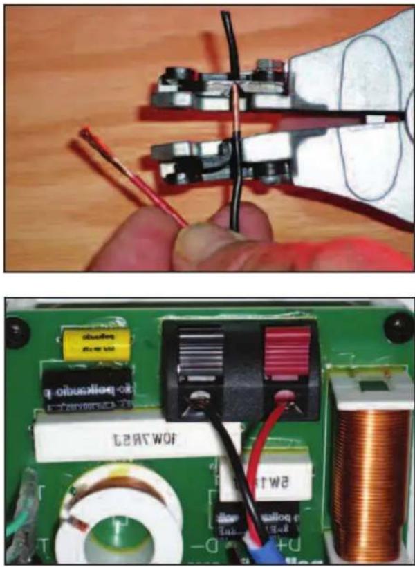
Now install the speaker into the wall and tighten up the dog-clamps with your screwdriver. Be careful not to over tighten the speaker—the dry wall or sheet rock could dimple, or break. This is most likely to happen if you are using a power driver. Set your power driver's torque setting to "1" to help avoid over-tightening screws.


View of rotating cam after installation from inside the wall.
Finally install the grill:
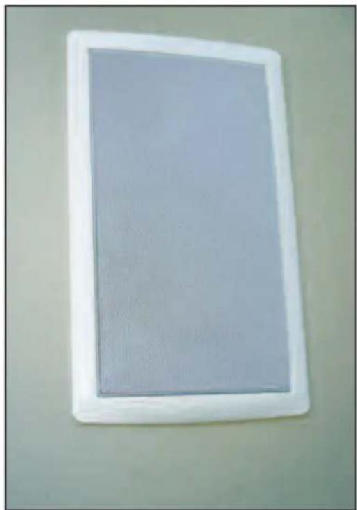
For a professional look we recommend terminating the cables near the receiver or amplifier with a wall plate, this allows a very clean finish, without any gaps or holes in the wall. Your friends will think a professional did the install! The simple install goes like this:
Install a single gang retrofit box: These are available at all home centers, cost about \$3.00 and are installed just like your speakers:


Terminate the speaker cable to the binding post inserts and install like this:


Now just connect to the amplifier. Congratulations, you're done!
Patching and restoring the wall
As we talked about above, sheet rock is a very forgiving building material. We suggest using a wall repair patch witch is a small section of wire or nylon mesh, some drywall joint tape and joint compound.
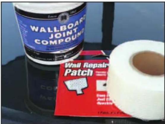
Here are the steps:
- Clean the wall and ceiling area, remove any loose debris.
- Remove the backing of the patch and apply to cover holes, press the self-adhering mesh against the surface. Be sure to overlap the remaining wall and ceiling by at least 2 1/4" in each direction.
- Apply joint compound (commonly referred to as "drywall mud") over patch. Spread evenly with a broad knife. Fill all depressions and joints. Cover an area 2" to 4" past the edges of the patch and tape.
- Feather edges out to match the existing surfaces. Allow material to dry.
- Sand area lightly to smooth and match the finish.
-
Repeat steps 3 & 4 if necessary to achieve desired finish, cleaning and sanding as you go.
-
Paint.
8 Refreshments, cold beer, and invite your good buddy Jack Daniels over to hear your system rock.
- INSTALLING YOUR IN-WALL OR IN-CEILING SPEAKERS
- SECTION 1: INTRODUCTION TO INSTALLING IN-WALL OR IN-CEILING POLK AUDIO SPEAKERS
- SAFETY AND CODE REVIEW
- PHOTOS AND DESCRIPTION OF THE TOOLS
- SECTION 2: POLK AUDIO IN-WALL AND IN-CEILING SPEAKER INSTALLATION GUIDE
- MATERIALS AND PREPARATION
- PLANNING WHERE TO RUN THE CABLE
- SCENARIO 1
- SCENARIO 2
- SCENARIO 3
- PLANNING YOUR CABLE ROUTES
- SECTION 3: CHECKING FOR OBSTACLES BEFORE INSTALLATION
- THEN
- SECTION 4: INSTALLING POLK SPEAKERS: CUTTING DRYWALL AND RUNNING SPEAKER CABLES
- SUPPLIES
- CUTTING SHEET ROCK
- INSTALLING THE SPEAKER CABLES
- RUNNING SPEAKER CABLE WITH ALTERNATING CURRENT OR AC LINES
- TIPS TO RUNNING CABLE IN EXISTING WALLS
- HORIZONTAL RUNS
- SECTION 5: SPEAKER INSTALLATION AND HOOK UP
- PATCHING AND RESTORING THE WALL
Brand : POLK
Model : SC65
Category : Loudspeaker