Sub10F - Subwoofer BOSTON ACOUSTICS - Free user manual and instructions
Find the device manual for free Sub10F BOSTON ACOUSTICS in PDF.

User questions about Sub10F BOSTON ACOUSTICS
0 question about this device. Answer the ones you know or ask your own.
Ask a new question about this device
Download the instructions for your Subwoofer in PDF format for free! Find your manual Sub10F - BOSTON ACOUSTICS and take your electronic device back in hand. On this page are published all the documents necessary for the use of your device. Sub10F by BOSTON ACOUSTICS.
USER MANUAL Sub10F BOSTON ACOUSTICS
natural_image
Isometric line drawing of a rectangular enclosure with a circular recess and two mounting brackets (no text or symbols)Boston
Boston Acoustics
Introduction
In many homes and installations, the deep bass of a powered subwoofer is desired, but often there is not a suitable location to install a box subwoofer. The Boston Sub10F In-Floor Subwoofer handily solves this dilemma. Located below the floor and powered by the companion Boston SA1 Subwoofer Power Amplifier, all that is visible in the listening room is a floor register.

natural_image
Line drawing of a simple architectural or mechanical structure with no visible text, numbers, or symbols.Warning: Always turn off the amplifier when connecting the subwoofer and any other components to the system.
Note: The Sub10F is an installed product. Installation should only be attempted by professional installers or those possessing skills in construction, the proper use of hand and power tools, knowledge of local building and fire codes, and a familiarity with the environment below the floor in which the subwoofer will be installed.
Placement
For maximum bass, place the Sub10F so its vent is near a corner or sidewall and is as close to the main speakers as possible.
Floor Register (Not supplied)
The Sub10F mounts in the floor directly below a floor register. The register should have a minimum air opening of 3 x 9". Return registers without moving parts should be used. If the register has moving louvers or other moving parts, they will need to be removed to prevent them from rattling.
Floor Thickness
As floors differ in thickness, it is important to measure the depth of the floor register and the thickness of the floor to confirm that the floor register will not be in contact with the subwoofer's grille.
Location Hazards
It is the nature of low-frequency energy (bass) to make objects vibrate. Care should be taken in planning the installation of the in-floor subwoofer to minimize the risk of room vibration and noise. Do not locate the in-floor subwoofer close to lamps or furniture that might rattle or vibrate. Some bass energy will be heard in the room below the subwoofer. If the ceiling below is finished, ceiling fixtures may rattle or vibrate.
It is recommended that in the area where the Sub10F is to be mounted, the subfloor is glued to the joists and extra nails are used to secure the subfloor. Be sure the joists to which the Sub10F is mounted are securely braced against each other so that the distance between them does not change and they are not able to move or shift (consult local building codes)
Amplifier Requirements & Wiring
The Sub10F must be used with the Boston SA1 Subwoofer Power Amplifier. Use with any other amplifier will result in poor performance. One SA1 Power Amplifier can power up to two Sub10F subwoofers. Only one Sub10F should be connected to each set of terminals on the SA1. If you are installing only one Sub10F, pre-wire so that a second one can be added, but do not connect the extra set of speaker wires to the SA1.
Set the equalization switch (EQ-MODE) on the back of the SA1 amplifier to the "FLOOR" position. We recommend the use of 16-gauge or larger speaker wire with both the Sub10F and SA1.
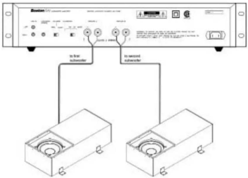
text_image
Boston 100 to first subwoofer to second subwooferService Access
If service is needed, the Sub10F's woofer can be removed through the access panel on the bottom of the subwoofer. If there is a finished ceiling below the Sub10F, ideally a door allowing access to the complete subwoofer enclosure, or at minimum, to the Sub10F's service panel, should be left in the ceiling below.
Preparation for Installation
1) Attach the supplied gasket to the subwoofer. See diagram below.
2) After deciding on the location of the Sub10F, use the supplied template to check for the fit of the subwoofer and location of the floor register. It is important to check both below the floor where the Sub10F is to be mounted and in the room where the floor register is to be located.
3) Use drywall or deck screws (not supplied) for mounting the Sub10F. Do not use wood screws.
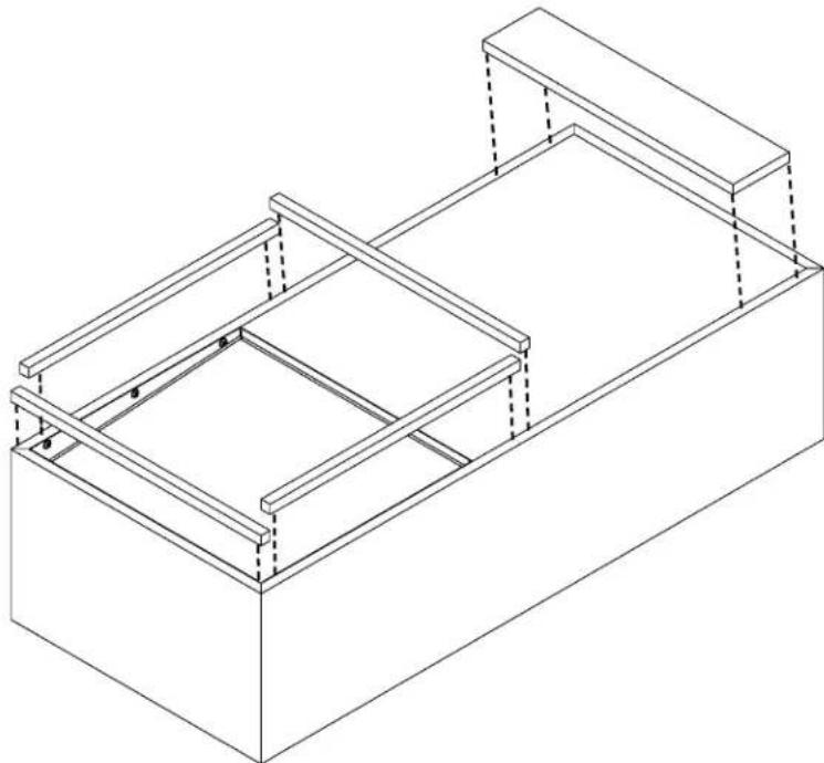
natural_image
Isometric line drawing of a two-story rectangular frame with internal supports and dashed lines indicating hidden edges (no text or symbols)Installation
Be sure to mount the Sub10F rigidly to the floor joists, as its tremendous output could cause unwanted vibration if the Sub10F is able to move.
Be sure the joists to which the Sub10F is mounted are securely braced against each other so that the distance between them does not change and they are not able to move or shift.
1) Measure the floor register. Cut the hole in the floor for the floor register.
2) If any nails are protruding from the subfloor above, cut or hammer them out of the way.
Note: If there is not going to be ceiling installed in the room below, it is best to mount the Sub10F after construction is complete. If the subwoofer must be installed while construction in the room above is still in progress, cover the hole for the floor register so that construction debris or liquids cannot fall onto the subwoofer.
3) With the hole for the floor register as a guide, hold the Sub10F in place and use the supplied brackets to mark for screw holes.
4) Drill pilot holes in the Sub10F before attaching screws. The Sub10F's cabinet is made of MDF (Medium Density Fiberboard), which can crack if pilot holes are not drilled.
5) The Sub10F's cabinet must be airtight. Seal any unused pilot holes with glue or caulk.
6) Attach the brackets to the subwoofer, and mount the brackets to the joists. Use wood shims, if needed, to hold the Sub10F tight to the sub-floor above.
Important: The gaskets on the subwoofer must form a good seal with the sub-floor above.
Installation (Cont.)
7) If you plan to attach the Sub10F directly to the joists using screws, use wood shims to prevent damage to the Sub10F enclosure. It is important to use wood shims so that there are no gaps between the sides of the Sub10F and the joists. Remember to drill pilot holes. See diagram below.
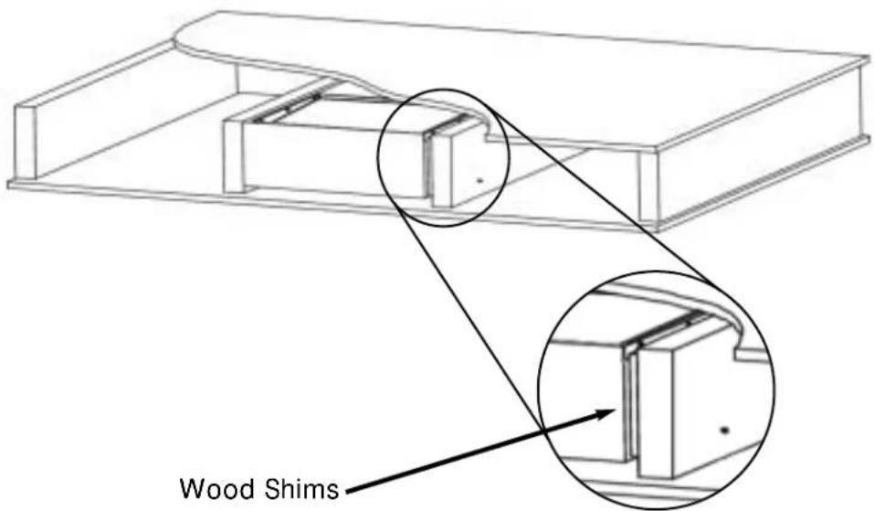
text_image
Wood Shims8) Attach the speaker wire securely to the terminals on the end of the Sub10F.
9) Install the floor register. For installations on hardwood floors, a foam gasket may need to be placed under the floor register.
Specifications
SA1 Power Amplifier Sub10F
| Frequency Response (±3dB) — 29–160Hz (with SA1) | ||
| Recommended Amplifier Power — Must use with SA1 amplifier | ||
| Nominal Impedance 8 Ohms | ||
| Bass Unit — 10" DCD | ^TM copolymer | |
| Amplifier Power < 1% THD 140 watts continuous, 8 ohms —210 watts continuous, 4 ohms | ||
| Crossover Frequency 40–160Hz 40-160Hz (on SA1)24dB/Octave Lowpass | ||
| Inputs L&R stereo RCA line level | —& LFE RCA line level forcrossover bypass | |
| 12-volt Trigger Input Voltage | 9–14 volts DC @ 1.5mA max. ^1/8" diameter female plug with tip positive | — |
| External Dimensions 3 | ^1/2 × 19 × 12^1/2" (89 x 483 x 318mm)[H x W x D w/o feet] ^3/8 × 19 × 12^1/2" (92 x 483 x 318mm)[H x W x D w/feet]2 EIA rack space w/feet removed | 14^1/16 × 31^1/2" (357 x 800.1mm) |
| Mounting Depth (from surface) | —8 | ^1/4" (209.55mm) ^9/4" including 1" gasket |
If Service Seems Necessary
First, contact the dealer from whom you purchased the subwoofer. If that is not possible, write to:
Boston Acoustics
300 Jubilee Drive
Peabody, MA 01960
Or contact us via email at support@bostona.com or by phone at 978-538-5000
We will promptly advise you of what action to take.
Limited Warranty
Boston Acoustics warrants to the original purchaser of our Sub10F In-Floor Subwoofer that the Sub10F will be free of defects in materials and workmanship for a period of five years from the date of purchase.
Your responsibilities are to install and use the product according to the instructions supplied, to provide safe and secure transportation to an authorized Boston service representative, and to present proof of purchase in the form of your sales slip when requesting service.
Excluded from this warranty is damage that might result from abuse, misuse, improper installation, accidents, shipping, or repairs/modifications by someone other than an authorized Boston Acoustics representative.
This warranty is limited to the Boston Acoustics Sub10F and does not cover damage to any associated equipment. This warranty does not cover the cost of removal, reinstallation, or repair of damage to the installation location caused by either the mounting or removal of the product.
This warranty is void if the serial number is defaced or removed.
Boston
Boston Acoustics
300 Jubilee Drive
Peabody, MA 01960 U.S.A.
978.538.5000
www.bostonacoustics.com
Boston and Boston Acoustics are registered trademarks and DCD is a trademark of Boston Acoustics, Inc.
© 2001 Boston Acoustics, Inc. All rights reserved.
Specifications subject to change without notice
042-001342-0