KY-B64BXBXD - Hob PANASONIC - Free user manual and instructions
Find the device manual for free KY-B64BXBXD PANASONIC in PDF.
| Brand | Panasonic |
| Model | KY-B64BXBXD |
| Product type | Induction hob |
| Number of cooking zones | 4 |
| Hob dimensions (W x D x H) | 607 x 536 x 57 mm |
| Cutout dimensions (W x D) | 560 x 490 mm |
| Power supply | 220-240 V single-phase or 380-415 V three-phase, 50 Hz, 40 A |
| Maximum total power | Approximately 9.2 kW (single-phase) or 7.2 kW (three-phase) |
| Surface material | Ceramic glass |
| Cooking zone diameters | 2 x 210 mm (front left and rear right), 2 x 150 mm (rear left and front right) |
| Main functions | Touch controls, automatic shut-off, pan detection, child lock |
| Maintenance and cleaning | Clean with a soft cloth and ceramic glass cleaner after cooling |
| Safety | Mandatory grounding, 30 mA residual current circuit breaker, automatic overheating cut-off |
| Installation | Built-in, requires a qualified electrician, minimum ventilation gap of 20 mm under the appliance |
| Weight (approx.) | 12 kg |
| Included accessories | 4 clamping brackets |
| Repairability | Repair by an approved professional, spare parts available on request |
Frequently Asked Questions - KY-B64BXBXD PANASONIC
User questions about KY-B64BXBXD PANASONIC
0 question about this device. Answer the ones you know or ask your own.
Ask a new question about this device
Download the instructions for your Hob in PDF format for free! Find your manual KY-B64BXBXD - PANASONIC and take your electronic device back in hand. On this page are published all the documents necessary for the use of your device. KY-B64BXBXD by PANASONIC.
USER MANUAL KY-B64BXBXD PANASONIC
Model No. KY-B84BX / KY-B84BG
KY-B64BX / KY-B64BG
English 2-15
Deutsch 16-29
Français 30-43
Nederlands 44-57
Safety Precautions
Contents
Safety Precautions 3
Installation Location 7
Accessories 7
Dimensions 8
Related Dimensional Drawings
for Custom Kitchens 10
Electrical Work 12
Installing the Appliance 14
Post-installation Checklist 15
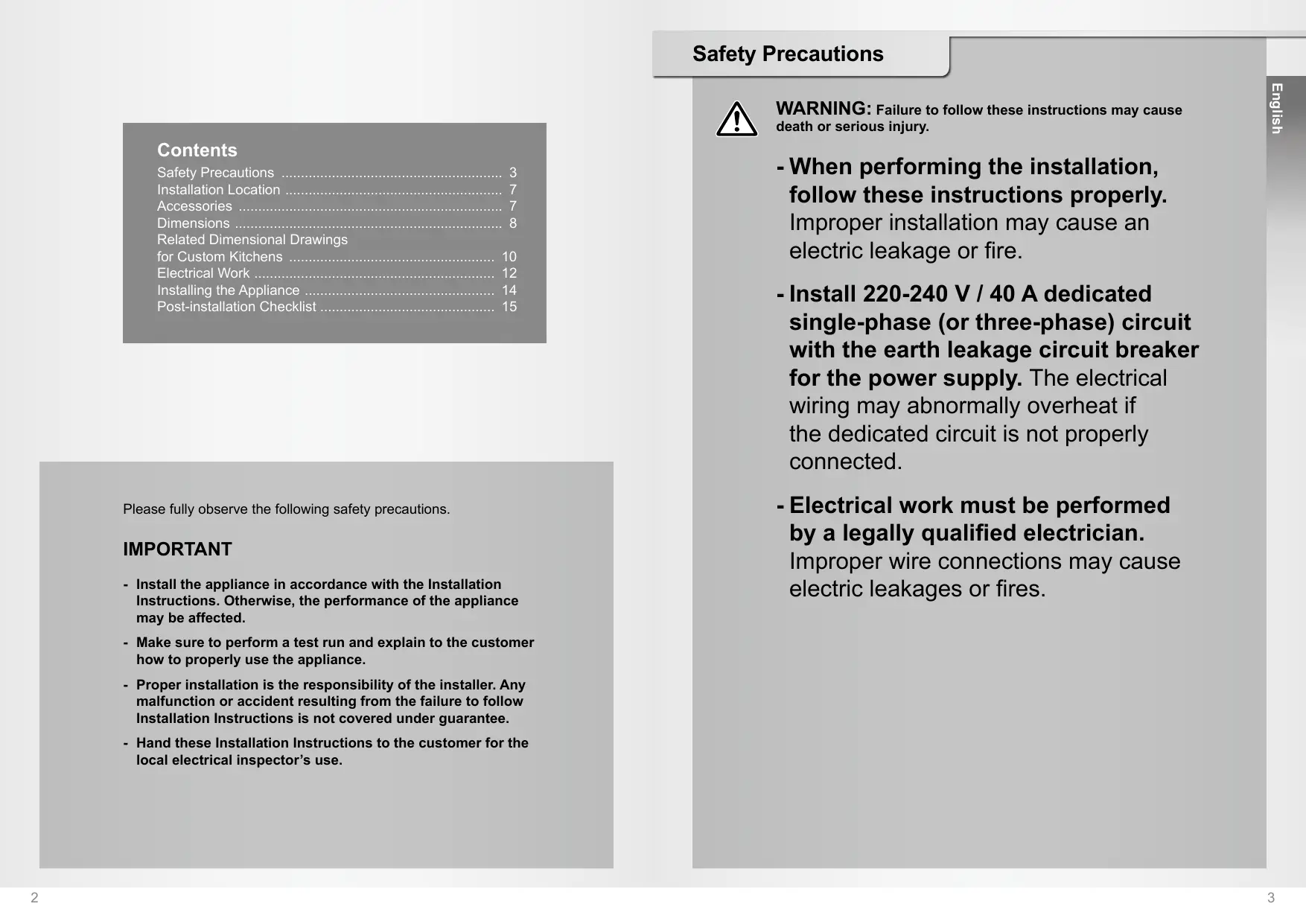
Please fully observe the following safety precautions.
IMPORTANT
- Install the appliance in accordance with the Installation Instructions. Otherwise, the performance of the appliance may be affected.
- Make sure to perform a test run and explain to the customer how to properly use the appliance.
- Proper installation is the responsibility of the installer. Any malfunction or accident resulting from the failure to follow Installation Instructions is not covered under guarantee.
- Hand these Installation Instructions to the customer for the local electrical inspector's use.

WARNING: Failure to follow these instructions may cause death or serious injury.
- When performing the installation, follow these instructions properly.
Improper installation may cause an electric leakage or fire.
- Install 220-240 V / 40 A dedicated single-phase (or three-phase) circuit with the earth leakage circuit breaker for the power supply. The electrical wiring may abnormally overheat if the dedicated circuit is not properly connected.
- Electrical work must be performed by a legally qualified electrician. Improper wire connections may cause electric leakages or fires.

WARNING: Failure to follow these instructions may cause death or serious injury.
- This appliance must be properly earthed following the electric laws. Earth line must not be connected to gas pipe, water pipe, earth of lightning rod and telephone.
Otherwise, it may cause electric shock in case of appliance breakdown or insulation breakdown.
- Have a qualified electrician earth the appliance. Improper earthing may cause an electric shock.
- Before performing the installation, definitely turn off the circuit breaker. This can prevent electric shock.
-
Do not touch high temperature parts, such as the top plate.
-
If the power cord is damaged, it must be replaced by the manufacturer or its service centre or a similar qualified person in order to avoid a hazard.
- Do not disassemble, repair or modify the appliance (the top plate, for example). Doing so may cause the appliance to operate abnormally and may result in danger.
- Do not step on the appliance, or drop heavy items on top of it. Cracks in the top plate may cause overheating, malfunctions or electric shocks.
- The power cord must be accurately connected to ensure the integrity of the connection. Improper wire connections may cause electric leakages or fires.

CAUTION: Failure to follow these instructions may cause injury or property damage.
- Use heat resistant materials for the countertop. However, do not use varnished materials as they might get discoloured. The material of the countertop should have heat resistance equal to or exceeding “laminated thermosetting high-pressure decorative sheets”. If the materials are not heat resistant, they may get deformed or cause a fire.
Installation Location
Observe the laws concerning the installation of the appliance.
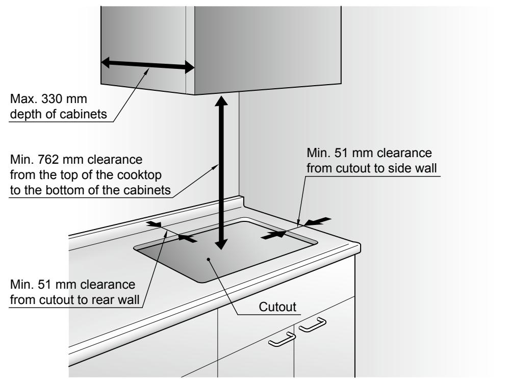
text_image
Max. 330 mm depth of cabinets Min. 762 mm clearance from the top of the cooktop to the bottom of the cabinets Min. 51 mm clearance from cutout to side wall Min. 51 mm clearance from cutout to rear wall CutoutFor more details on cutout, see page 11.
Accessories
Clamp
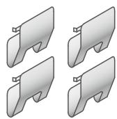
( 4 pieces )
KY-B84BX / KY-B84BG
Top view
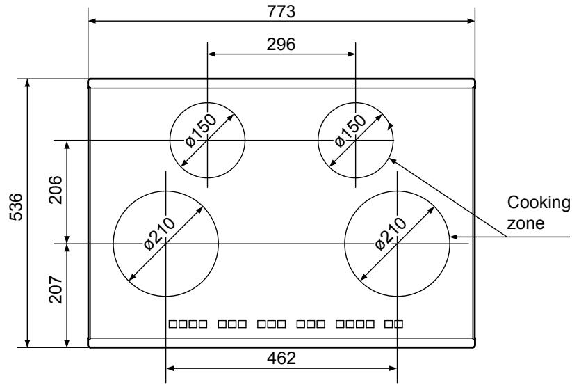
text_image
773 296 536 206 207 462 ø150 ø150 ø210 ø210 Cooking zoneFront view
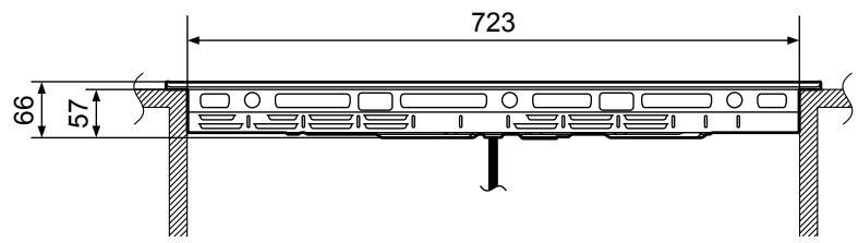
text_image
723 66 57Side view
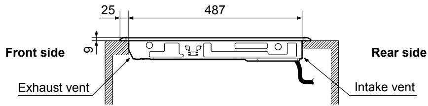
text_image
25 487 Front side Exhaust vent Rear side Intake ventPower cord length: approx. 1.2 m (Sheath length: approx. 1.1 m)
KY-B64BX / KY-B64BG
Top view
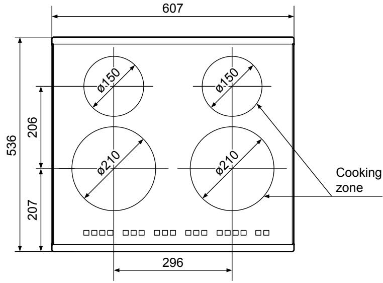
text_image
607 536 206 207 296 ø150 ø210 ø150 ø210 Cooking zoneFront view
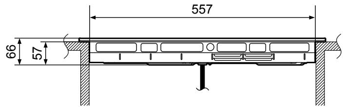
text_image
557 66 57Side view

text_image
25 487 Front side Exhaust vent Rear side Intake ventPower cord length: approx. 1.2 m (Sheath length: approx. 1.1 m)
Related Dimensional Drawings for Custom Kitchens
(measurement: mm)
Side view
(measurement: mm)
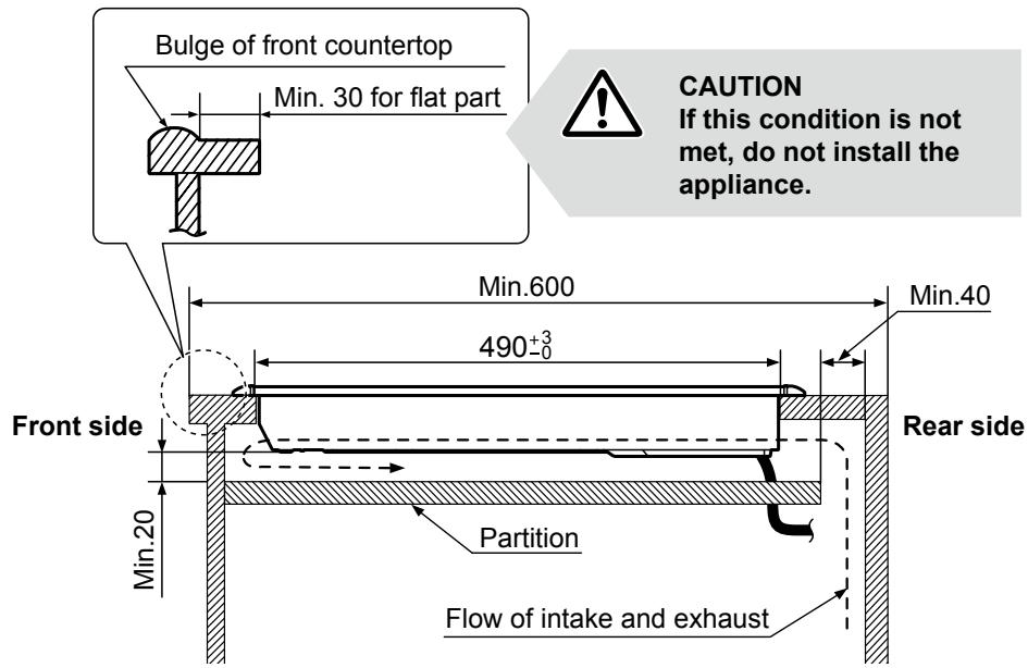
text_image
Bulge of front countertop Min. 30 for flat part CAUTION If this condition is not met, do not install the appliance. Min.600 490±3/0 Min.40 Front side Rear side Min.20 Partition Flow of intake and exhaustWhen installing a partition inside the cabinet,
- Allow for a minimum of 20 mm extra space underneath the bottom of the appliance for air circulation.
- Allow for a minimum of 40 mm extra space in rear of the partition.
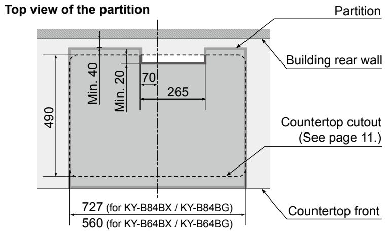
text_image
Top view of the partition Partition Building rear wall Min. 40 Min. 20 70 265 490 Countertop cutout (See page 11.) 727 (for KY-B84BX / KY-B84BG) 560 (for KY-B64BX / KY-B64BG)When installing the cooktop above an oven,
- Allow for Panasonic ovens: HL-BT62S / HL-BT62B only. (As of January 2013)
- Allow for extra spaces for air circulation as shown below.
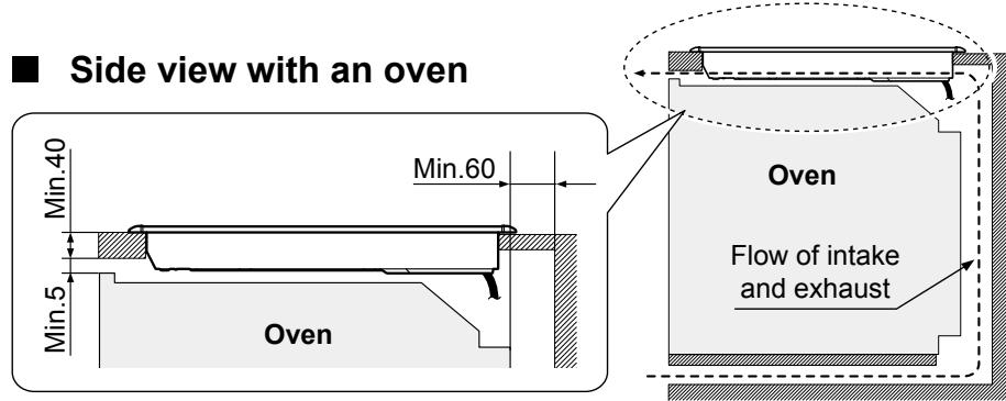
text_image
Side view with an oven Min.40 Min.5 Min.60 Oven Oven Flow of intake and exhaust■ Dimensions of countertop cutout
KY-B84BX / KY-B84BG
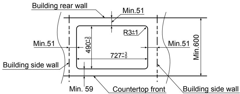
text_image
Building rear wall Min.51 R3±1 490±3 727±3 Min.51 Min.600 Building side wall Building side wall Min. 59 Countertop front Building side wallKY-B64BX / KY-B64BG
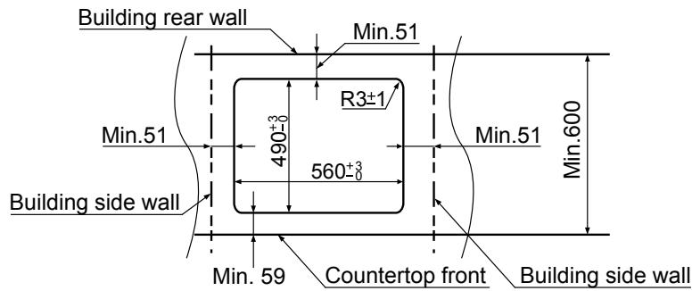
text_image
Building rear wall Min.51 R3±1 490±3 560±3 Min.51 Min.51 Building side wall Min. 59 Countertop front Building side wall Min.600
WARNING
Electrical work must be performed by a legally qualified electrician.
■ Electrical requirements
- This appliance must be supplied with the proper voltage and frequency, and connected to an individual, properly earthed branch circuit, protected by a circuit breaker or fuse. (The rating plate is on the bottom of the appliance.)
- This appliance is not fitted with other means for disconnection from the supply mains having a contact separation in all poles that provide full disconnection under overvoltage category III conditions. Means for disconnection must be incorporated in the fixed wiring in accordance with the wiring rules.
- You must use a two-wire, single-phase A.C. 220-240 V, 40 A, 50 Hz electrical system. (It is also possible to use a four-wire, three-phase.) If you connect to aluminum wiring, properly use connectors approved for use with aluminum wiring.
- Check with the local utilities for electrical codes applied in the area. Failure to wire the appliance according to governing codes may result in a hazardous condition.
- After installation, show the customer where the breaker for the appliance is located.
■ Installation of the earth leakage circuit breaker
- In accordance with the electrical wiring rules, incorporate the earth leakage circuit breaker in the home electrical wire.
- Follow the specification of the earth leakage circuit breaker as follows. Rated current: 40 A, rated sensitivity current: 30 mA
■ Electrical connections
1. Turn off power.
Turn off power at the circuit breaker or remove fuses to the appliance branch circuit.
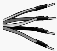
2. Connect the power cord.
Connect the power cord in accordance with all governing codes and ordinances.
- Single-phase connection (220-240 V \~ 50 Hz)
Connect the wires in accordance with the instructions given in the following table and diagram:
| Electrical cable | Wire connection |
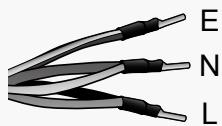 | E: Yellow / Green(Connect to the earth terminal)N: Grey and Blue togetherL: Black and Brown together(Connect to the live terminal) |
- Three-phase connection (380-415 V 2N\~ 50 Hz)
Separate the L wires and connect them in accordance with the instructions given in the following table and diagram:
| Electrical cable | Wire connection | |
 | ENL1L2 | E: Yellow / Green(Connect to the earth terminal)N: Grey and Blue togetherL1: BlackL2: Brown(Connect to the live terminal) |
Installing the Appliance

WARNING
Do not disassemble the top plate. Connected wire may become loose and cause a malfunction.
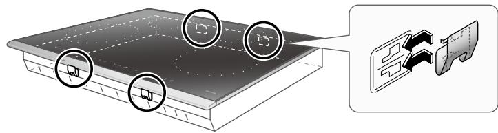
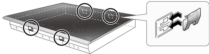
1. Fasten the clamps to the main unit
(4 places on the front and rear).
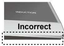
- Put the Cushion UP underneath the main unit to act as a buffer in order to prevent the countertop from getting damaged.
- Match the clamp grips with the holes on the sides of the main unit, then slide the clamp from the right to the left to fasten them to the main unit.
natural_image
Diagram of a layered electronic component with a top panel and base, showing internal structure and mounting points (no text or symbols)Cushion UP

text_image
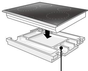
Diagram illustrating a device with labeled components and an accompanying schematic showing internal structure and component alignment.2. Embed the main unit in the countertop cutout while keeping it is as level as possible.
- Do not drop the unit on the countertop.
- Press down on top of the main unit to make sure that the frame solidly rests on the countertop.
- Make sure that the spaces between the countertop and the under surface of the top frame are even in the front, rear, left and right.
natural_image
Diagram showing a mechanical assembly with a component being lowered into a housing (no text or symbols present)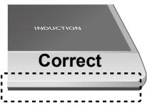
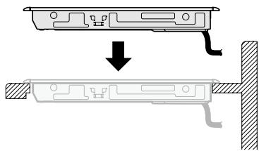
3. Connect the power cord
See page 13.

CAUTION
If the cabinet does not have an opening in the front, the wiring needs to be connected before the main unit is embedded into the countertop.
Post-installation Checklist
Upon completing installation, check and mark off the following items.
| Checklist | Checked | |
| Appearance | - Does the appliance not look like it is tilted to the front, rear, left or right?- Is the frame not lifted up?- Is the top plate clean? | |
| Electrical work | - Is the power supply a single-phase (220-240 V ~), or a three-phase (380-415 V 2N~)? | |
| - Has the earth been installed?- Has the earth leakage circuit breaker been installed? | ||
| Electrical testing | 1. Touch Ⓐ to turn on the main power.- Does the main power light light up?2. Touch the following keys to check function of each IH heater:- Left front heaterDoes “7” (heat level display)- Left rear heater flash?- Right front heater [W430]- Right rear heater   |
Does "7" (heat level display) flash?
- Make sure to turn off each IH heater and the main power switch after performing electrical testing.
- Hand the Operating Instructions, Installation Instructions, and Guarantee Certificate to the customer.
I hereby certify that installation has been completed.
Signature of installer
Inhalt
natural_image
Diagram of a layered electronic component with a highlighted section and mounting base (no text or symbols)Kissen UP
text_image
Diagram illustrating a device with labeled components and an accompanying schematic showing internal structure and component alignment.natural_image
Diagram showing a mechanical assembly with a component being lowered into a housing (no text or symbols present)

natural_image
Diagram of a layered electronic component with a top panel and internal structure, showing no text or symbols.text_image
Diagram illustrating a device's internal components with magnified view of the screen and folder, showing labeled parts and directional arrows.natural_image
Diagram of a layered electronic component with a top panel and base, showing internal structure and mounting points (no text or symbols)UP-zijde kussen
text_image
Diagram illustrating a device's internal components with magnified view of the screen and display panelnatural_image
Diagram showing a mechanical assembly with a downward arrow indicating a process or transformation (no text or symbols present)