
EY-7420 - Cordless Tools PANASONIC - Free user manual and instructions
Find the device manual for free EY-7420 PANASONIC in PDF.

| Product type | Cordless drill/driver |
| Brand | Panasonic |
| Model | EY-7420 |
| Total length | 145 mm |
| Weight (with battery) | 0.63 kg |
| Power supply | Li-ion 7.2 V DC battery (model EY9L20) |
| No-load speed (low) | 0 - 300 min⁻¹ |
| No-load speed (high) | 0 - 900 min⁻¹ |
| Max torque (low speed) | 6.0 N·m |
| Max torque (high speed) | 2.0 N·m |
| Clutch torque settings | 21 positions (0.3 to 4.0 N·m) |
| Chuck | Hexagonal quick |
| Main functions | Screwing (clutch), drilling wood and metal |
| LED light | Yes, work area illumination |
| Hanging ring | Yes, adjustable |
| Bit lock | Yes (up to 5 N·m) |
| Motor brake | Yes, immediate stop |
| Auxiliary handle | Included |
| Maintenance and cleaning | Clean with a dry cloth, do not use water or solvent |
| Safety | Hearing protection, insulated gripping surfaces, dust mask, switch lock |
| Spare parts and repairability | Contact an authorized Panasonic service center |
| Charger | Model EY0L20, charges in 35 min (usable) / 60 min (full) |
| Screw capacities | Machine screw: M5 (low), M4 (high) |
| Range | Cordless tools |
Frequently Asked Questions - EY-7420 PANASONIC
User questions about EY-7420 PANASONIC
0 question about this device. Answer the ones you know or ask your own.
Ask a new question about this device
Download the instructions for your Cordless Tools in PDF format for free! Find your manual EY-7420 - PANASONIC and take your electronic device back in hand. On this page are published all the documents necessary for the use of your device. EY-7420 by PANASONIC.
USER MANUAL EY-7420 PANASONIC
Cordless Drill & Driver
Akku-Bohrschrauber
natural_image
Illustration of a handheld electric drill press (no text or symbols visible)Before operating this unit, please read these instructions completely and save this manual for future use.
| (A) | Bit holderBithalterPorte-mèchePortapuntaBithouderSoporte para brocasBitholderBitshållareBit-holderTerän pidike | (B) | Clutch handleKupplungsringPoignée de l'embrayageImpugnatura frizioneKoppelingshandgreepMango de embragueKoblinghåndtagKopplingshandtagKoblingshåndtakKytkimen kahva |
| (C) | Speed selector switchBereichsschalterInterrupteur de sélection de vitesseRegolatore di velocitàSnelheidskeuzeschakelaarInterruptor selector de velocidadHastighedsvælgerHastighetsomkopplareHastighetskontrollNopeuden valintakytkin | (D) | Forward/Reverse leverRechts/Linkslauf SchalterLevier d'inversion marche avant-marche arrièreLeva di avanzamento/inversioneVoorwaarts/achterwaarts-hendelPalanca de avance/inversiónGreb til forlæns/baglæns retningRiktningsomkopplareForover/Revers bryterEteenpäin/taaksepäin vipu |
| (E) | Hook ringHakenringAnneau d'accrochageAnello di aggancioHaakringAnillo de ganchoPåhægtningsringKrokringBeltekrokKiinnitysrengas | (F) | Battery pack release buttonAkku-EntriegelungsknopfBouton de libération de batterie autonomeTasto di rilascio pacco batteriaAccu-ontgrendeltoetsBotón de liberación de bateríaUdløserknap til batteripakningFrigöringsknapp för batteriUtløserknapp for batteripakkeAkkupaketin irrotuspainike |
| (G) | Battery packAkkuBatterie autonomePacco batteriaAccuBateríaBatteripakningBatteriBatteripakkeAkku | (H) | LED lightLED-LeuchteLumière DELLuce LEDLED-lampjeLuz indicadoraLED-lysLED-ljusLED-lysLED-valo |
| (I) | Variable speed control triggerBetriebsschalterGåchette de commande de vitesseGrilletto di controllo velocità variableStartschakelaar variabele snelheidDisparador del control de velocided variableKontroludløser for variabel hastighedSteglös varvtalsreglerareHovedbryter, trinnløsNopeudensäätökytkin | (J) | Battery chargerLadegerätChargeur de batterieCaricabatterieAcculaderCargador de bateríaBatteriopladerBatteriladdareBatteriladerAkkulaturi |
| (K) | Pack coverAkkuabdeckungCouvercle de la batterie autonomeCoperchio paccoAccudekselCubierta de bateríaPakningsdækselBatteriskyddPakkedekselAkkukotelon kansi | ||
Original instructions: English Translation of the original instructions: Other languages
I. INTENDED USE
These tools can be used to tighten screws in clutch mode and to drill holes in wood and metal in drill mode.
Read the Safety Instructions booklet and the following before using.
II. ADDITIONAL SAFETY RULES
1) Wear ear protectors. Exposure to noise can cause hearing loss.
2) Use auxiliary handle supplied with the tool. Loss of control can cause personal injury.
3) Hold power tools by insulated gripping surfaces when per-forming an operation where the cutting tool may contact hidden wiring; contact with a “live” wire will make exposed metal parts of the tool “live” and shock the operator.
4) Wear a dust mask, if the work causes dust.
5) Be aware that this tool is always in an operating condition, since it does not have to be plugged into an electrical outlet.
6) When drilling or driving into walls, floors, etc., “live” electrical wires may be encountered. DO NOT TOUCH THE CHUCK OR ANY FRONT METAL PARTS OF THE TOOL! Hold the tool only by the plastic handle to prevent electric shock in case you drill or drive into a “live” wire.
7) If the bit becomes jammed, im-mediately turn the trigger switch off to prevent an overload, which can damage the battery pack or motor. Use reverse motion to loosen jammed bits.
8) Do NOT operate the For-ward/Reverse lever when the trigger switch is on. The battery will discharge rapidly and damage to the unit may occur.
9) During charging, the charger may become slightly warm. This is normal. Do NOT charge the battery for a long period.
10) When storing or carrying the tool, set the Forward/Reverse lever to the center position (switch lock).
11) Do not strain the tool by holding the speed control trigger halfway (speed control mode) so that the motor stops.
12) Do not operate the speed selector switch (LOW-HIGH) while pulling on the speed control trigger. This can cause the rechargeable battery to wear quickly or damage the in-ternal mechanism of the motor.
WARNING
- Do not use other than the Panasonic battery packs that are designed for use with this rechargeable tool.
- Panasonic is not responsible for any damage or accident caused by the use of recycled or counterfeit battery pack.
- Do not dispose of the battery pack in a fire, or expose it to excessive heat.
- Do not drive the likes of nails into the battery pack, subject it to shocks, dismantle it, or attempt to modify it.
- Do not allow metal objects to touch the battery pack terminals.
- Do not carry or store the battery pack in the same container as nails or similar metal objects.
- Do not charge the battery pack in a high-temperature location, such as next to a fire or in direct sunlight. Otherwise, the battery may overheat, catch fire, or explode.
- Never use other than the dedicated charger to charge the battery pack. Otherwise, the battery may leak, overheat, or explode.
• After removing the battery pack from the tool or the charger, always reattach the pack cover. Otherwise, the battery contacts could be shorted, leading to a risk of fire.
- When the Battery Pack Has Deteriorated, Replace It with a New One. Continued use of a damaged battery pack may result in heat generation, ignition or battery rupture.
| Symbol | Meaning |
| V | Volts |
| --- | Direct current |
| n_o | No load speed |
| ...min ^-1 | Revolutions or reciprocations per minutes |
| Ah | Electrical capacity of battery pack |
| Rotation only | |
| To reduce the risk of injury, user must read and understand instruction manual. | |
| For indoor use only. |
III. ASSEMBLY
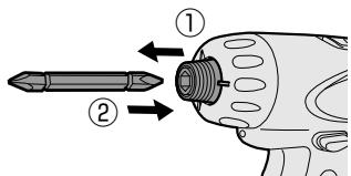
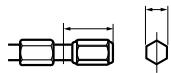
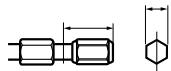
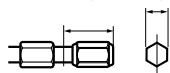
Attaching or Removing Bit
NOTE:
When attaching or removing a bit, disconnect battery pack from tool or place the switch in the center position (switch lock).
1. Attachment
① While pulling the bit holder
② Insert the bit
③ Release the bit holder
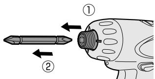
2. Removal
① While pulling the bit holder
② Remove the bit
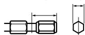
9.5 mm (3/8") - 13 mm (33/64") 6.35 mm (1/4")
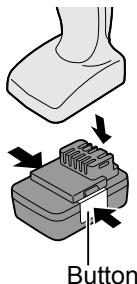
Attaching or Removing Battery Pack
- To connect the battery pack: Insert the battery pack firmly into the main body.
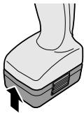
- To remove the battery pack: Push on the button from the side to release the battery pack.
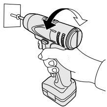
- The speed increases with the amount of depression of the trigger. When beginning work, depress the trigger slightly to start the rotation slowly.
- A feedback electronic controller is used to give a strong torque even in low speed.
- The brake operates when the trigger is released and the motor stops immediately.
NOTE:
When the brake operates, a braking sound may be heard. This is normal.
Switch and Forward/Reverse Lever Operation
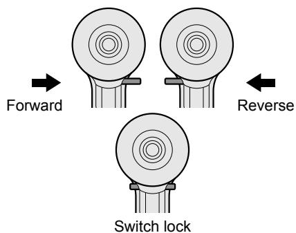
CAUTION:
To prevent damage, do not operate Forward/Reverse lever until the bit comes to a complete stop.
Forward Rotation Switch Operation
- Push the lever for forward rotation.
- Depress the trigger switch slightly to start the tool slowly.
- The speed increases with the amount of depression of the trigger for efficient tightening of screws and drilling. The brake operates and the chuck stops immediately when the trigger is released.
- After use, set the lever to its center position (switch lock).
Reverse Rotation Switch Operation
- Push the lever for reverse rotation. Check the direction of rotation before use.
- Depress the trigger switch slightly to start the tool slowly.
- After use, set the lever to its center position (switch lock).
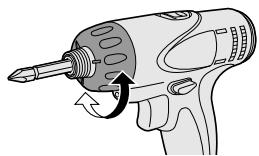
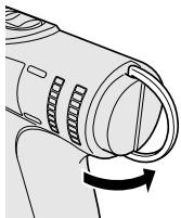
Clutch Torque Setting
Adjust the torque to one of the 21 clutch settings.
Use for Drilling
- When using for drilling, set the clutch at "2" position.
- Use a bit designed for drilling.
CAUTION:
Set the clutch scale at the alignment position before actual operation.
natural_image
Illustration of a handheld electric drill with a screwdriver and lever mechanism (no text or symbols)| Setting | Torque | Use |
| 1 | Approx: 0.3 N·m(3.0 kgf-cm or 2.6 in-lbs) | For driving screws |
| 5 | Approx: 1.0 N·m(11 kgf-cm or 8.8 in-lbs) | |
| 9 | Approx: 1.8 N·m(18 kgf-cm or 15.9 in-lbs) | |
| 13 | Approx: 2.5 N·m(26 kgf-cm or 22.1 in-lbs) | |
| 17 | Approx: 3.3 N·m(33 kgf-cm or 29.2 in-lbs) | |
| 21 | Approx: 4.0 N·m(41 kgf-cm or 35.4 in-lbs) | |
| Approx: 6 N·m(61 kgf-cm or 53.1 in-lbs) | For powerful driving screws and drilling |
- When using at high speeds, set the clutch at 10 or below. (Operation stops at the maximum torque of 1.5 ~N · m (15 kgf-cm) when the scale is higher.)
- The auto shut-off function may become inoperable at high clutch settings when battery power drops. Recharge the battery in that case.
Speed Selection
Choose a low or high speed to suit the use.
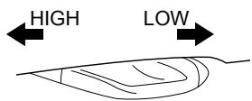
The more the variable speed control trigger is pulled, the higher the speed becomes.
CAUTION:
- Check the speed selector switch before use.
- Use at low speed when high torque is needed during operation. (Using at high speed when high torque is required may cause a motor breakdown.)
- Do not operate the speed selector switch (LOW-HIGH) while pulling on the speed control trigger. This can cause the rechargeable battery to wear quickly or damage the internal mechanism of the motor.
* See specifications for "MAXIMUM RECOMMENDED CAPACITIES".
CAUTION:
- To prevent excessive temperature increase of the tool surface, do not operate the tool continuously using two or more battery packs. The tool needs cool-off time before switching to another pack.
- Do not close up vent holes on the sides of the body during operation. Otherwise, the machine function is adversely affected to cause a failure.
- Do NOT strain the tool (motor). This may cause damage to the unit.
- Use the tool in such a way as to prevent the air from the body vent holes from blowing directly onto your skin. Otherwise, you may get burned.
Bit-locking Function
- With the trigger switch not engaged and a screwdriver bit locked in place, the tool can be used as a manual screwdriver (up to 5 N·m, 51 kgf·cm, 44.3 in-lbs).
There will be a little play in the chuck, but this is not a malfunction.
- This feature is handy for tightening screws that require more torque than the maximum torque of the driver (position on the clutch), for confirming the tightness of a screw or to loosen an extremely tight screw.
natural_image
Illustration of a hand using a handheld electric drill to adjust a cylindrical device (no text or symbols visible)How to Use Hook Ring
WARNING!
- When the main unit is held by the hook ring, avoid jumping or running with it. Doing so may cause the ring to slip and the main unit may fall.
This may result in an accident or injury. - When the hook ring is not used, be sure to return it to the original position. The hook ring may catch on something. This may result in an accident or injury.
- When the unit is hooked by the hook ring, do not attach driver bits to the unit. A sharp edge object, such as a drill bit, may cause injury or an accident.
- Use a hooking tool (carabiner etc.) that does not come off easily. If this unit falls it may cause accident.
Using Hook Ring
- Release the hook ring.
natural_image
Diagram of a cylindrical device with internal components and an arrow indicating rotation (no text or symbols)-
Attach the hook ring to the hooking tool.
-
Use a hooking tool (carabiner etc.) that does not come off easily. If this unit falls it may cause accident.
- Ensure that there is no contact with the surroundings when a hook ring is used.
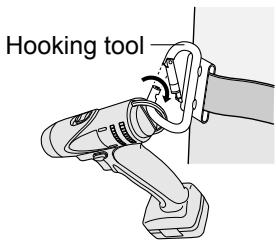
- Return the hook ring after use.
LED Light
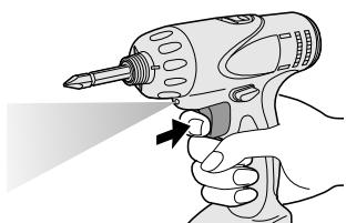
natural_image
Illustration of a hand using a power drill to apply a tool (no text or symbols present)Pull the trigger.
The light illuminates with very low current, and it does not adversely affect the performance of the tool during use or its battery capacity.
CAUTION:
- The built-in LED light is designed to illuminate the small work area temporarily.
- Do not use it as a substitute for a regular flashlight, since it does not have enough brightness.
Caution: DO NOT STARE INTO BEAM. Use of controls or adjustments or performance of procedures other than those specified herein may result in hazardous radiation exposure.
[Battery Pack]
For Appropriate Use of Battery Pack
Li-ion Battery Pack
- For optimum battery life, store the Li-ion battery pack following use without charging it.
- When charging the battery pack, confirm that the terminals on the battery charger are free of foreign substances such as dust and water etc. Clean the terminals before charging the battery pack if any foreign substances are found on the terminals.
The life of the battery pack terminals may be affected by foreign substances such as dust and water etc. during operation.
- When battery pack is not in use, keep it away from other metal objects like: paper clips, coins, keys, nails, screws, or other small metal objects that can make a connection from one terminal to another.
Shorting the battery terminals together may cause sparks, burns or a fire.
- When operating the battery pack, make sure the work place is well ventilated.
- When the battery pack is removed from the main body of the tool, replace the battery pack cover immediately in order to prevent dust or dirt from contaminating the battery terminals and causing a short circuit.
natural_image
Line drawing of a mechanical device with a rectangular block and attached clamped components (no text or symbols)Battery Pack Life
The rechargeable batteries have a limited life. If the operation time becomes extremely short after recharging, replace the battery pack with a new one.
Battery Recycling
ATTENTION:
For environmental protection and recycling of materials, be sure that it is disposed of at an officially assigned location, if there is one in your country.
[Battery Charger]
Charging
CAUTION:
- If the temperature of the battery pack falls approximately below -10^ (14°F), charging will automatically stop to prevent degradation of the battery.
- The ambient temperature range is between 0^ (32°F) and 40°C (104°F). If the battery pack is used when the battery temperature is below 0^ (32°F), the tool may fail to function properly.
- When charging a cool battery pack (below 0^ (32^) ) in a warm place, leave the battery pack at the place and wait for more than one hour to warm up the battery to the level of the ambient temperature.
- Cool down the charger when charging more than two battery packs consecutively.
- Do not insert your fingers into contact hole, when holding charger or any other occasions.
To prevent the risk of fire or damage to the battery charger.
- Do not use power source from an engine generator.
- Do not cover vent holes on the charger and the battery pack.
- Unplug the charger when not in use.
NOTE:
Your battery pack is not fully charged at the time of purchase. Be sure to charge the battery before use.
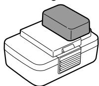
Battery charger
- Plug the charger into the AC outlet.
- Insert the battery pack firmly into the charger.
natural_image
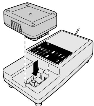
Diagram of a device with an open lid and internal components, showing no text or symbols- During charging, the charging lamp will be lit. When charging is completed, an internal electronic switch will automatically be triggered to prevent overcharging.
- Charging will not start if the battery pack is warm (for example, immediately after heavy-duty operation).
The orange standby lamp will be flashing until the battery cools down. Charging will then begin automatically. - The charge lamp (green) will flash slowly once the battery is approximately 80% charged.
- When charging is completed, the charging lamp in green color will turn off.
- If the temperature of the battery pack is 0^ C or less, charging takes longer to fully charge the battery pack than the standard charging time.
Even when the battery is fully charged, it will have approximately 50% of the power of a fully charged battery at normal operating temperature. - Consult an authorized dealer if the charging lamp (green) does not turn off.
- If a fully charged battery pack is inserted into the charger again, the charging lamp lights up. After several minutes, the charging lamp in green color will turn off.
LAMP INDICATIONS
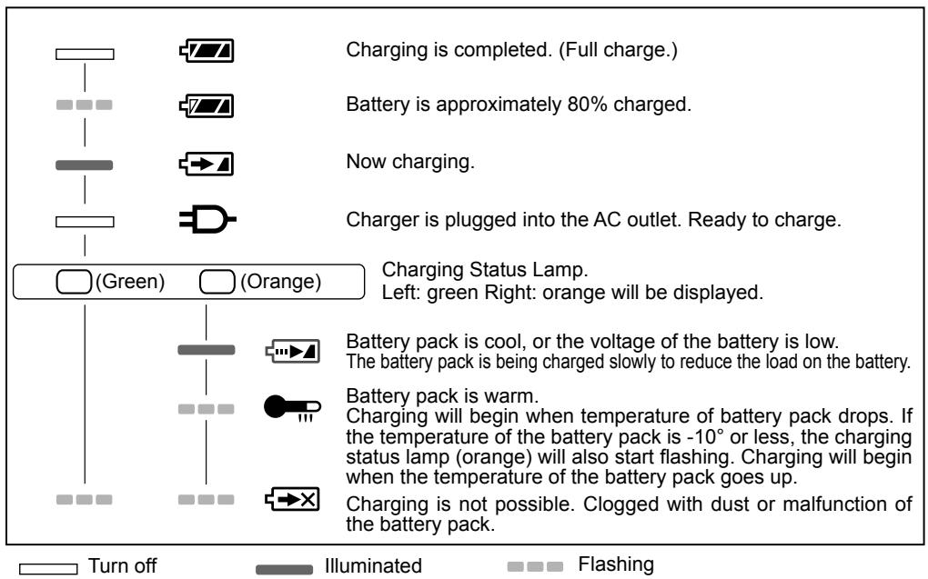
Information for Users on Collection and Disposal of Old Equipment and used Batteries
These symbols on the products, packaging, and/or accompanying documents mean that used electrical and electronic products and batteries should not be mixed with general household waste.
For proper treatment, recovery and recycling of old products and used batteries, please take them to applicable collection points, in accordance with your national legislation and the Directives 2002/96/EC and 2006/66/EC.
By disposing of these products and batteries correctly, you will help to save valuable resources and prevent any potential negative effects on human health and the environment which could otherwise arise from inappropriate waste handling.
For more information about collection and recycling of old products and batteries, please contact your local municipality, your waste disposal service or the point of sale where you purchased the items.
Penalties may be applicable for incorrect disposal of this waste, in accordance with national legislation.
For business users in the European Union
If you wish to discard electrical and electronic equipment, please contact your dealer or supplier for further information.
[Information on Disposal in other Countries outside the European Union]
These symbols are only valid in the European Union. If you wish to discard these items, please contact your local authorities or dealer and ask for the correct method of disposal.
Note for the battery symbol (bottom two symbol examples):
This symbol might be used in combination with a chemical symbol. In this case it complies with the requirement set by the Directive for the chemical involved.
V. MAINTENANCE
Use only a dry, soft cloth for wiping the unit. Do not use a damp cloth, thinner, benzine, or other volatile solvents for cleaning.
In the event that the inside of the tool or battery pack is exposed to water, drain and allow to dry as soon as possible.
Carefully remove any dust or iron filings that collect inside the tool. If you experience any problems operating the tool, please contact your nearest authorised service center.
VI. ACCESSORIES
Use only bits suitable for size of drill's chuck.
VII. APPENDIX
MAXIMUM RECOMMENDED CAPACITIES
| Model | EY7420 | |
| Screw driving | Machine screw | Low : M5High : M4 |
VIII. SPECIFICATIONS
MAIN UNIT
| Model | EY7420 | |
| Motor voltage | 7.2 V DC | |
| No load speed | Low | 0 - 300 min ^-1 (rpm) |
| High | 0 - 900 min ^-1 (rpm) | |
| Maximum torque | Low | 6.0 N·m (61 kgf-cm, 53.24 in-lbs) |
| High | 2.0 N·m (20 kgf-cm, 17.75 in-lbs) | |
| Clutch torque | Approx. 0.3 N·m (3 kgf-cm, 2.6 in-lbs) – 4.0 N·m (41 kgf-cm, 35.6 in-lbs) | |
| Overall length | 145 mm (5-7/10") | |
| Weight (with battery pack) | 0.63 kg (1.39 lbs) | |
BATTERY PACK
| Model | EY9L20 |
| Storage battery | Li-ion |
| Battery voltage | 7.2 V DC (3.6 V × 2 cells) |
| Charging time | Usable: 35 min |
| Full: 60 min |
NOTE: This chart may include models that are not available in your area.
Please refer to the latest general catalogue.
For the dealer name and address, please see the included warranty card.
BATTERY CHARGER
| Model | EY0L20 |
| Rating | See the rating plate on the bottom of the charge. |
| Weight | 0.43 kg (0.95 lbs) |
NOTE: This chart may include models that are not available in your area.
Please refer to the latest general catalogue.
For the dealer name and address, please see the included warranty card.
2. Abnehmen
9,5 mm (3/8") - 13 mm (33/64") 6,35 mm (1/4")
natural_image
Illustration of a mechanical device with a downward arrow indicating motion (no text or symbols)natural_image
Illustration of a drill bit with a screwdriver and handle (no text or symbols)natural_image
Illustration of a hand using a handheld electric drill to lift a motor (no text or symbols present)natural_image
Diagram of a handheld device with a circular button and directional arrow (no text or symbols)natural_image
Illustration of a hand holding a drill bit with a tool, no text or symbols presentnatural_image
Line drawing of a mechanical device with a rectangular block and a base plate (no text or symbols)natural_image
Diagram of a device with an open base and internal components, showing no text or symbols2. Enlèvement
9,5 mm (3/8") - 13 mm (33/64") 6,35 mm (1/4")

natural_image
Illustration of a mechanical device with a black arrow pointing to the base (no text or symbols)natural_image
Illustration of a drill bit with a screwdriver and handle (no text or symbols)natural_image
Illustration of a hand using a handheld electric drill to lift a power supply (no text or symbols present)natural_image
Diagram of a mechanical device with a rotating knob and curved arrow indicating rotation (no text or symbols)natural_image
Illustration of a hand holding a screwdriver with a tool, showing motion (no text or symbols)Tirez la gâchette.
natural_image
Isometric line drawing of a mechanical device with a rectangular block and base plate (no text or symbols)natural_image
Diagram of a device with an open lid and internal components, showing no text or symbols2. Rimozione
9,5 mm (3/8") - 13 mm (33/64") 6,35 mm (1/4")

natural_image
Illustration of a screwdriver with a circular motion arrow indicating tool movement (no text or symbols)natural_image
Illustration of a hand using a handheld electric drill to lift a power supply (no text or symbols present)natural_image
Diagram of a cylindrical device with internal components and a curved arrow indicating rotation (no text or symbols)natural_image
Illustration of a hand using a power drill with a tool, no text or symbols presentnatural_image
Line drawing of a mechanical device with a rectangular block and a side tab (no text or symbols)natural_image
Diagram of an electronic device with a central display and internal components, showing no text or symbols.2. Verwijderen
9,5 mm (3/8") - 13 mm (33/64") 6,35 mm (1/4")

natural_image
Illustration of a mechanical device with a downward arrow indicating motion (no text or symbols)natural_image
Illustration of a disassembled electric drill with a screwdriver and rotary knob (no text or symbols)| Instelling | Draaimoment | Gebruik |
| 1 | Ongeveer: 0,3 N·m(3,0 kgf-cm or 2,6 in-lbs) | Voor vastdraaien van schroeven |
| 5 | Ongeveer: 1,0 N·m(11 kgf-cm or 8,8 in-lbs) | |
| 9 | Ongeveer: 1,8 N·m(18 kgf-cm or 15,9 in-lbs) | |
| 13 | Ongeveer: 2,5 N·m(26 kgf-cm or 22,1 in-lbs) | |
| 17 | Ongeveer: 3,3 N·m(33 kgf-cm or 29,2 in-lbs) | |
| 21 | Ongeveer: 4,0 N·m(41 kgf-cm or 35,4 in-lbs) | |
| Ongeveer: 6 N·m(61 kgf-cm or 53,1 in-lbs) | Voorkrachtigvastdraaienvanschroevenen boren |
natural_image
Illustration of a hand using a handheld electric drill to lift a motor (no text or symbols present)natural_image
Diagram of a device handle with a circular knob and directional arrow (no text or symbols)natural_image
Illustration of a hand holding a drill bit with a tool, no text or symbols presentnatural_image
Line drawing of a mechanical device with a rectangular block and a label (no text or symbols)natural_image
Diagram of an electronic device with a top panel and internal components, showing no text or symbols.2. Desmontaje
9,5 mm (3/8") - 13 mm (33/64") 6,35 mm (1/4")

natural_image
Diagram showing a foot pressing a button into a device with arrows indicating motion (no text or symbols present)Botón
natural_image
Illustration of a drill bit with a screwdriver and handle (no text or symbols)| Ajuste | Par | Uso |
| 1 | Aprox.: 0,3 N·m(3,0 kgf-cm o 2,6 in-lbs) | Para introducir tornillos |
| 5 | Aprox.: 1,0 N·m(11 kgf-cm o 8,8 in-lbs) | |
| 9 | Aprox.: 1,8 N·m(18 kgf-cm o 15,9 in-lbs) | |
| 13 | Aprox.: 2,5 N·m(26 kgf-cm o 22,1 in-lbs) | |
| 17 | Aprox.: 3,3 N·m(3,3 kgf-cm o 29,2 in-lbs) | |
| 21 | Aprox.: 4,0 N·m(41 kgf-cm o 35,1in-lbs) | |
| Aprox.: 6 N·m(61 kgf-cm o 53,1 in-lbs) | Para introducir tornillos con fuerza y perforar |
natural_image
Illustration of a hand using a handheld electric drill to lift a motor (no text or symbols present)natural_image
Diagram of a mechanical device with a knob and rotating arrow (no text or symbols)natural_image
Illustration of a hand using a power drill with a tool, no text or symbols presentTire del activador.
natural_image
Line drawing of a mechanical device with a rectangular block and a base plate (no text or symbols)natural_image
Diagram of an electronic device with internal components and a dashed line indicating assembly (no text or symbols present)2. Afmontering
9,5 mm (3/8") - 13 mm (33/64") 6,35 mm (1/4")

natural_image
Diagram showing a foot pressing down on a mechanical component with arrows indicating force or movement (no text or symbols present)Knap
IV. BETJENING [Hoveddel]
Omskifterbetjening
natural_image
Illustration of a screwdriver with a circular motion arrow indicating tool movement (no text or symbols)| Indstilling | Moment | Brug |
| 1 | Ca. 0,3 N·m(3,0 kgf-cm or 2,6 in-lbs) | Til skrue-idrivning |
| 5 | Ca. 1,0 N·m(11 kgf-cm or 8,8 in-lbs) | |
| 9 | Ca. 1,8 N·m(18 kgf-cm or 15,9 in-lbs) | |
| 13 | Ca. 2,5 N·m(26 kgf-cm or 22,1 in-lbs) | |
| 17 | Ca. 3,3N·m(33 kgf-cm or 29,2 in-lbs) | |
| 21 | Ca. 4,0 N·m(41 kgf-cm or 35,4 in-lbs) | |
| Ca. 6 N·m(61 kgf-cm or 53,1 in-lbs) | For powerful driving screws and drilling |
natural_image
Illustration of a hand using a handheld electric drill to lift a motor (no text or symbols present)natural_image
Diagram of a handheld device with a rotary knob and scroll wheel (no text or symbols)natural_image
Illustration of a hand holding a screwdriver with a tool, no text or symbols presentTræk i triggeren.
natural_image
Illustration of a rectangular electronic device with a lid and base, no text or symbols presentBatteripakningens levetid
natural_image
Diagram of a device with an open base and internal components, showing no text or symbols9,5 mm (3/8") - 13 mm (33/64") 6,35 mm (1/4")
natural_image
Line drawing of a handheld electric drill with screwdriver and trigger mechanism (no text or symbols)natural_image
Simple line drawing of a boat hull with two arrows indicating direction (no text or symbols)natural_image
Illustration of a hand using a handheld electric drill bit to lift a power supply (no text or symbols present)natural_image
Diagram of a mechanical component with a rotating knob and curved arrow indicating rotation (no text or symbols)natural_image
Illustration of a hand holding a drill bit with a tool, no text or symbols presentnatural_image
Illustration of a rectangular electronic device with a lid and base, no text or symbols presentnatural_image
Diagram of a device with an open lid and internal components, showing no text or symbols- Demontering
9,5 mm (3/8") - 13 mm (33/64") 6,35 mm (1/4")

Montere eller demontere batteripakken
natural_image
Diagram showing a foot pressing a button into a device with directional arrows indicating movement (no text or symbols present)Knapp
IV. BETJENING [Hoveddel]
natural_image
Illustration of a screwdriver with a circular motion arrow indicating tool movement (no text or symbols)| Innstilling | Dreiemoment | Bruk |
| 1 | Cirka: 0,3 N·m(3,0 kgf-cm eller 2,6 in-lbs) | For å skru inn skruer |
| 5 | Cirka: 1,0 N·m(11 kgf-cm eller 8,8 in-lbs) | |
| 9 | Cirka: 1,8 N·m(18 kgf-cm eller 15,9 in-lbs) | |
| 13 | Cirka: 2,5 N·m(26 kgf-cm eller 22,1 in-lbs) | |
| 17 | Cirka: 3,3 N·m(33 kgf-cm eller 29,2 in-lbs) | |
| 21 | Cirka: 4,0 N·m(41 kgf-cm eller 35,4 in-lbs) | |
| Cirka: 6 N·m(61 kgf-cm eller 53,1 in-lbs) | For kraftkrevende skruer og boring |
natural_image
Illustration of a hand using a handheld electric drill to lift a motor (no text or symbols present)natural_image
Diagram of a mechanical device with a rotating knob and curved arrow indicating rotation (no text or symbols)-
Fest beltekroken til verktøyet.
-
Bruk en krok (karabinkrok eller lignende) som ikke glipper lett. Hvis enheten faller, kan den forårsake skade.
- Sikre at det ikke er kontakt med omgivelsene når en beltekrok brukes.
![PANASONIC EY-7420 - BETJENING [Hoveddel] - 1](/content/2019/08/105309/images/0b9cc1a76ed2f4b72581a32e2d67b1ef09134b2e860daf88b96f57e496db0a5b.jpg)
natural_image
Illustration of a hand using a power tool to apply a black arrow (no text or symbols present)Trykk på avtrekkeren.
natural_image
Line drawing of a mechanical device with a rectangular block and a label (no text or symbols)natural_image
Diagram of a device with an open lid and internal components, showing no text or symbols.- Under lading lyser ladelampen hele tiden.
Slike symboler på produkter, emballasje, og/eller på medfølgende dokumenter betyr at brukte elektriske/elektroniske produkter og batterier ikke må blandes med vanlig husholdningsavfall.
2. Irrottaminen
9,5 mm (3/8") - 13 mm (33/64") 6,35 mm (1/4")
natural_image
Illustration of a screwdriver with a circular motion arrow indicating tool movement (no text or symbols)| Asetus | Momentti | Käytä |
| 1 | Noin: 0,3 N·m(3,0 kgf-cm tai 2,6 in-lbs) | Ruuva-ukseen |
| 5 | Noin: 1,0 N·m(11 kgf-cm tai 8,8 in-lbs) | |
| 9 | Noin: 1,8 N·m(18 kgf-cm tai 15,9 in-lbs) | |
| 13 | Noin: 2,5 N·m(26 kgf-cm tai 22,1 in-lbs) | |
| 17 | Noin: 3,3 N·m(33 kgf-cm tai 29,2 in-lbs) | |
| 21 | Noin: 4,0 N·m(41 kgf-cm tai 35,4 in-lbs) | |
| Noin: 6 N·m(61 kgf-cm tai 53,1 in-lbs) | Voimak-kaaseenruuva-ukseenja pora-ukseen |
natural_image
Illustration of a hand using a handheld electric drill to lift a motor (no text or symbols present)natural_image
Diagram of a cylindrical device with internal components and an arrow indicating rotation (no text or symbols)natural_image
Illustration of a hand holding a drill bit with a tool, no text or symbols presentPaina liipaisinta.
natural_image
Isometric line drawing of a mechanical device with a rectangular block and a handle (no text or symbols)Akun kestoikä
natural_image
Diagram of an electronic device with a switch and internal components (no text or symbols)VIII. TEKNISET TIEDOT
PÄÄLAITE
Panasonic Testing Center
Winsbergring 15,
22525 Hamburg,
Germany
Panasonic Corporation
1006,Kadoma,Osaka 571-8501,Japan
http://panasonic.net
EN. DE. FR. IT. NL. ES. DA. SV. NO. FI
EY971074201 201302
Printed in Japan
- INTENDED USE
- ADDITIONAL SAFETY RULES
- WARNING
- ASSEMBLY
- Attaching or Removing Bit
- NOTE:
- Attachment
- Removal
- Attaching or Removing Battery Pack
- Switch and Forward/Reverse Lever Operation
- CAUTION:
- Forward Rotation Switch Operation
- Reverse Rotation Switch Operation
- Clutch Torque Setting
- Use for Drilling
- Speed Selection
- Bit-locking Function
- How to Use Hook Ring
- WARNING!
- Using Hook Ring
- LED Light
- [Battery Pack]
- For Appropriate Use of Battery Pack
- Li-ion Battery Pack
- Battery Pack Life
- Battery Recycling
- ATTENTION:
- [Battery Charger]
- Charging
- Battery charger
- LAMP INDICATIONS
- Information for Users on Collection and Disposal of Old Equipment and used Batteries
- For business users in the European Union
- [Information on Disposal in other Countries outside the European Union]
- Note for the battery symbol (bottom two symbol examples):
- MAINTENANCE
- ACCESSORIES
- APPENDIX
- SPECIFICATIONS
- Abnehmen
- Enlèvement
- Rimozione
- Verwijderen
- Desmontaje
- Afmontering
- BETJENING [Hoveddel]
- Omskifterbetjening
- Batteripakningens levetid
- Montere eller demontere batteripakken
- Irrottaminen
- Akun kestoikä
- TEKNISET TIEDOT
Brand : PANASONIC
Model : EY-7420
Category : Cordless Tools