
M393A4G43AB3-CWE - Memory Card SAMSUNG - Free user manual and instructions
Find the device manual for free M393A4G43AB3-CWE SAMSUNG in PDF.


| Product Type | Memory Module |
| Brand | Samsung |
| Model | M393A4G43AB3-CWE |
| Memory Type | DDR4 |
| Capacity | 32 GB |
| Speed | 2666 MHz (PC4-21300) |
| Form Factor | Registered DIMM (RDIMM) |
| Pin Count | 288-pin |
| Rank | Dual Rank |
| Voltage | 1.2 V |
| Operating Temperature | 0°C to 85°C |
| Dimensions (L x W x H) | 133.35 x 31.25 x 3.8 mm |
| Weight | 30 g (approx) |
| Compliance | RoHS, REACH |
| ESD Protection | Anti-ESD wrist strap recommended |
| Installation Method | Insert evenly with both hands, align notch |
| Handling Precautions | Avoid bending, twisting, or dropping; use gloves |
| Socket Compatibility | DDR4 RDIMM compatible slots |
| Warranty | Limited lifetime warranty (by Samsung policy) |
| Maintenance | Clean with dry cloth; avoid solvents |
Frequently Asked Questions - M393A4G43AB3-CWE SAMSUNG
User questions about M393A4G43AB3-CWE SAMSUNG
0 question about this device. Answer the ones you know or ask your own.
Ask a new question about this device
Download the instructions for your Memory Card in PDF format for free! Find your manual M393A4G43AB3-CWE - SAMSUNG and take your electronic device back in hand. On this page are published all the documents necessary for the use of your device. M393A4G43AB3-CWE by SAMSUNG.
USER MANUAL M393A4G43AB3-CWE SAMSUNG
natural_image
Illustration of various Samsung and DDR4 memory chips with labeled components (no text or symbols on the chip surfaces)Module Handling Guide
How to handle the module
Recently module failure related with Active/Passive/Component crack has increased.
Main root causes are wrong handling method and mechanical damage.
Current products have more cap. & resistors and the sizes of those passives are reduced and most of them are located around edge area.
These characteristics require more cautious module handling method.
This guide book tries to find out tendency and range of module crack pattern based on experiments from several aspects. The main purpose is to reinforce Samsung's process control and help customer effectively control module handling process.
Test methods are PCB Bow, Twist, Drop Test, UTM(Universal Testing Machine) Test for DRAM, Resister & Capacitor. We observed crack phenomena and tendency through the datum and pictures. Tested products are limited to Registered DIMM [RDIMM], Unbuffered DIMM [UDIMM] and BOC PKG based Module, therefore test results might be different when applied to other products.
Memory Module Introduction
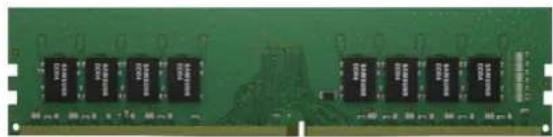
natural_image
Green printed circuit board with multiple black integrated circuits (no visible text or symbols)Unbuffered DIMM
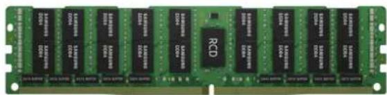
natural_image
Green integrated circuit chip with multiple 12-pin memory chips and a central RCD (no visible text or symbols)Load Reduced DIMM

Registered DIMM

natural_image
Green printed circuit board with multiple black and white memory chips (no visible text or symbols)SODIMM
natural_image
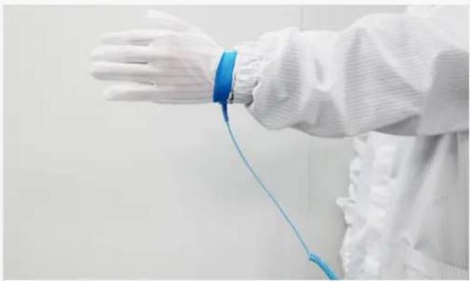
Person in white protective suit with blue wristband and blue cord, no visible text or symbols
natural_image
Close-up of gloved hands handling a black plastic tray with greenish contents, no visible text or symbols
natural_image
Person in white lab coat and gloves holding a memory chip (no visible text or symbols)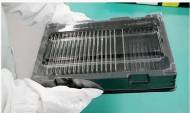
natural_image
Close-up of a gloved hand holding a transparent plastic tray with internal channels, placed on a green surface (no visible text or symbols)- Anti-ESD * straps should be used.
• The strap should be linked to your body.
*ESD : Electro Static Discharge
-
Modules should be picked up from packing trays only one-by-one.
• Product should be handled at the conductive mat. -
Do not grab packages. Hold only the edge of the PCB with both hands.
- Wear gloves when handling.
- Tray must be covered when handling module tray.

natural_image
Person in cleanroom suit holding a green circuit board with a red diagonal line (no text or symbols visible)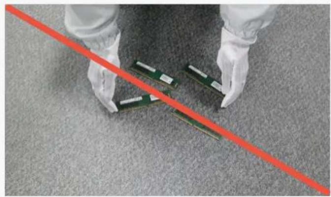
natural_image
Person in white gloves and gloves handling multiple RAM chips on a carpet, with a red diagonal line overlay (no text or symbols)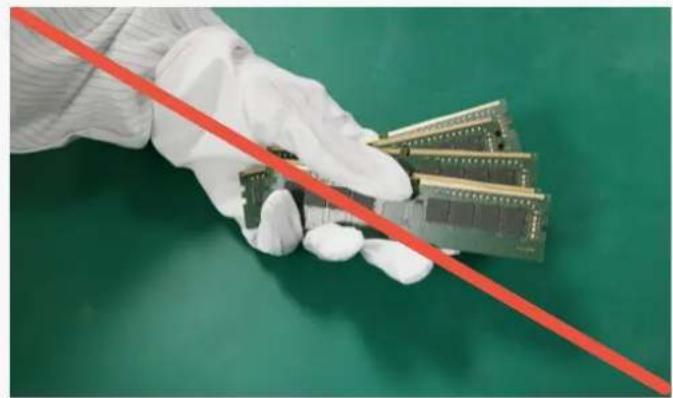
natural_image
Hand in white glove holding a series of microcontroller chips against a green background (no text or symbols visible)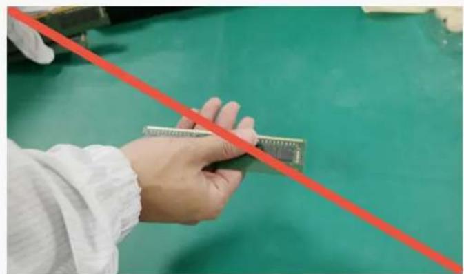
natural_image
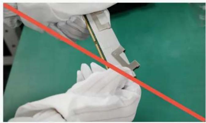
Close-up of a hand holding a small electronic component against a green background, with a red diagonal line overlay (no text or symbols visible)- Do not twist or bow a module.
- Do not drop modules on the floor.
- Do not grip several modules using one hand.
- Do not touch module without gloves. It can cause tab contamination.
natural_image
Close-up of gloved hands using a tool on a green surface, with a red diagonal line overlay (no text or symbols)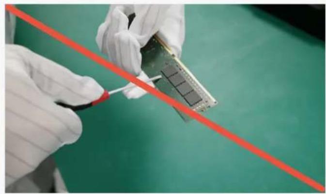
natural_image
Close-up of gloved hands holding a microchip with a red diagonal line against a green background (no text or symbols visible)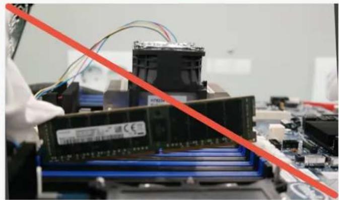
natural_image
Close-up of a computer motherboard with a red diagonal line overlay, showing a stack of RAM chips and connected cables (no visible text or symbols)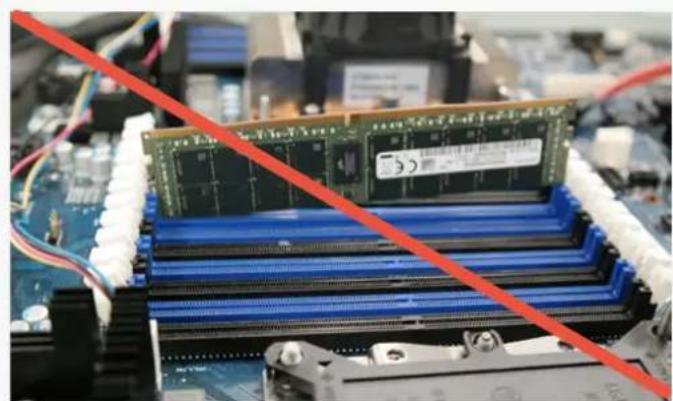
natural_image
Close-up of a computer RAM module with a green memory card placed on top, connected to a blue CPU socket and a red diagonal line (no text or symbols visible)- Do not detach H/S * or clip. (FDHS product) *H/S : Heat Spreader
- Handling modules near tools is prohibited because hard metal objects can damage Module.
- Do not insert the module by seating one end first then seating the other. (This is called zippering or rock)
- Do not insert module upper side.

natural_image
Close-up of electronic circuit boards with a red diagonal line overlay (no readable text or symbols)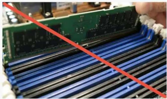
natural_image
Close-up of a green RAM module being processed with blue ribbeds, no visible text or symbols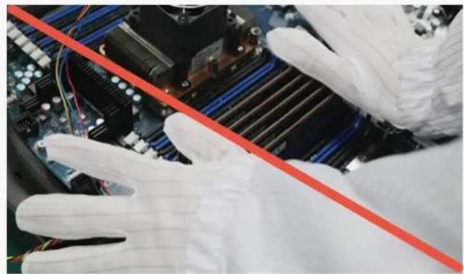
natural_image
Close-up of gloved hands adjusting a red diagonal line on a computer motherboard (no visible text or symbols)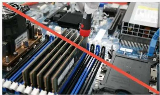
natural_image
Close-up of a computer motherboard with a red diagonal line indicating a performance gap (no text or symbols visible)- Do not insert module between sockets.
- Do not insert key notch reverse.
- Do not insert several modules at the same time. (or simultaneously)
- Do not use metal tools when the socketing.

natural_image
Close-up of a computer motherboard with CPU socket and drive bays (no visible text or symbols)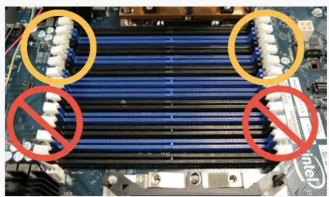
natural_image
Close-up of a computer motherboard with blue and white CPU slots, marked by yellow circles and red prohibition signs (no readable text or symbols)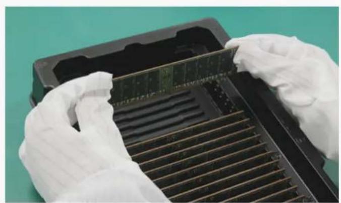
natural_image
Close-up of gloved hands installing a memory card into a rack (no visible text or symbols)
natural_image
Close-up of hands assembling a memory module with blue and black components (no visible text or symbols)-
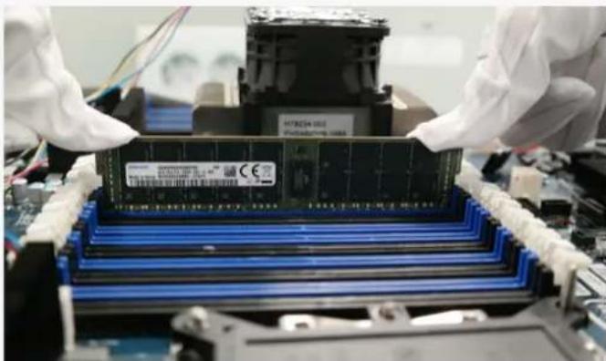
Socketing must be conducted before turn-on.
-
Ensure that both latch ejectors of connector are fully opened.
-
Grip the module edge side with both hands. (avoid touching component area)
-
Align module to socket notch & side guide.
natural_image
Close-up of gloved hands assembling a memory chip into a motherboard (no visible text or symbols)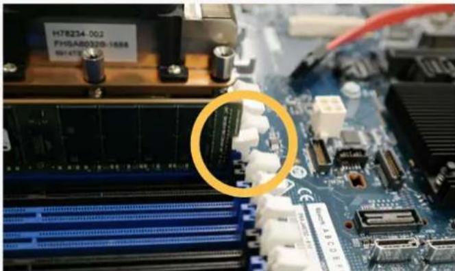
natural_image
Close-up of a computer motherboard with visible slots, chips, and connectors (no readable text or symbols)-
Press down both edge side of module at the same time.
-
Confirm latch ejectors closed properly.
We validated the possibility of cracking tendencies through various tests. Various products, Environments, and characteristics of tools can cause errors and affect test results.
However, the most important conclusion that can be deduced from the tests is that special caution against mechanical damage and handling errors should be taken from the point of unpacking modules to inserting into the sockets on system boards.
Recent memory module products are structurally weak to external damage due to the increasing numbers of ICs and passive components and the unit's diminishing size.
It's difficult to predict and find out clear root causes of failures related with BOC PKG passive components due to many variances and circumstances. However, the above guidelines for memory module handling based on test results should help with crack-related problems and make more effective process control possible.
About Samsung Electronics Co., Ltd.
Samsung inspires the world and shapes the future with transformative ideas and technologies. The company is redefining the worlds of TVs, smartphones, wearable devices, tablets, digital appliances, network systems, and memory, system LSI and LED solutions. For the latest news, please visit the Samsung Newsroom at news.samsung.com.
Copyright © 2018 Samsung Electronics Co., Ltd. All rights reserved. Samsung is a registered trademark of Samsung Electronics Co., Ltd. Specifications and designs are subject to change without notice. Nonmetric weights and measurements are approximate. All data were deemed correct at time of creation. Samsung is not liable for errors or omissions. All brand, product, service names and logos are trademarks and/or registered trademarks of their respective owners and are hereby recognized and acknowledged.
Fio is a registered trademark of Fio Corporation. Intel is a trademark of Intel Corporation in the U.S. and/or other countries. Linux is a registered trademark of Linus Torvalds. PCI Express and PCIe are registered trademarks of PCI-SIG. Toggle is a registered trademark of Toggle, Inc.
Brand : SAMSUNG
Model : M393A4G43AB3-CWE
Category : Memory Card