
XRS 969 - Gps COBRA - Free user manual and instructions
Find the device manual for free XRS 969 COBRA in PDF.


| Product Type | GPS-enabled Radar Detector |
| Brand | Cobra |
| Model | XRS 969 |
| Category | GPS |
| Power Source | 12V DC (cigarette lighter adapter) |
| Display | Multi-color OLED display |
| Dimensions | 4.75 x 2.75 x 1.25 inches |
| Weight | 5.6 oz (159 g) |
| Operating Temperature | -20°C to 70°C (-4°F to 158°F) |
| Detection Bands | X, K, Ka, Ku, Laser, POP, VG-2 |
| GPS Features | GPS lockouts, red light camera alerts, speed camera alerts, position marking |
| Voice Alerts | Yes, with adjustable volume |
| Mounting | Sleek magnetic mount included |
| Update Method | USB connection to computer (requires internet) |
| Warranty | Limited 1-year warranty |
| Maintenance | Clean lens with soft cloth; keep vents clear |
| Security | Anti-theft bracket system |
| Spare Parts Availability | Mounting bracket, power cord, and USB cable available separately |
| General Information | Intended for use in vehicles; complies with FCC regulations |
Frequently Asked Questions - XRS 969 COBRA
User questions about XRS 969 COBRA
0 question about this device. Answer the ones you know or ask your own.
Ask a new question about this device
Download the instructions for your Gps in PDF format for free! Find your manual XRS 969 - COBRA and take your electronic device back in hand. On this page are published all the documents necessary for the use of your device. XRS 969 by COBRA.
USER MANUAL XRS 969 COBRA
The Cobralineofqualityproductsincludes:
CB Radios
microTALK® Radios
Radar/Laser Detectors
Safety Alert® Traffic Warning Systems
Mobile GPS Navigation Systems
HighGear ^® Accessories
CobraMarine® VHF Radios
Marine Chartplotters
Power Inverters
Accessories
FormoreInformationario
orderanycroulProducts, please call your website:
www.cobra.com
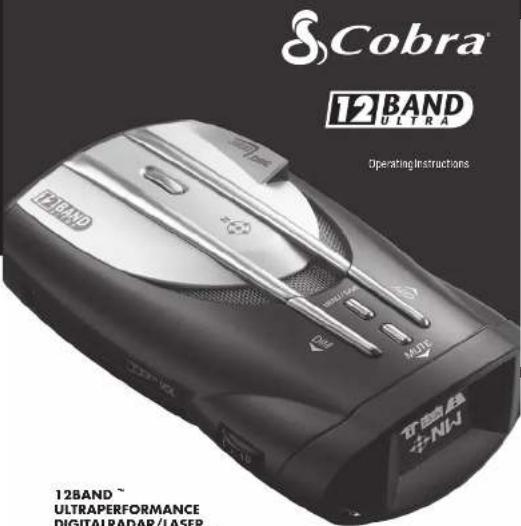
12BAND
ULTRAPERFORMANCE
DIGITALRADAR/LASER
DETECTORWITHATREME RANGESUPERHETERODYNE® TECHNOLOGY
XRS969
[无法识别]

ImportantInformationand CustomerAssistance
Important Information
FederalLawsGoverningtheUseofRadarDetectors
It is not again a federal law or receiver radtransmissions with your Cobraradar laser detector. The Communications Act of 324 guarantees your right to receive radiotransmissions on any frequency. Locally, that contravenes this Act, while illegal, maybe forced by your local law enforcement officials until and unless they are prohibited from doing school federal court action.
SafetyAlert
Use this product is not intended to, and does not ensure that motorists or passengers will not be involved in traffic accidents. It is only intended to alert the motorist that an emergency vehicle equipped with a Cobra Safety Alert transmitter within ranges defined by that product. Please call local fire and police department bottle of coverage exists in your area.
SafeDriving
Motorists, as well as operators of emergency or service vehicles, are expected to exercise all due caution while using this product, and to obey all applicable traffic laws.
SecurityofYourVehicle
Beforeleavingyourvehicle,alwaysremembertoconcealyourradardetector inorderloreducethepossibilityofbreak-inandthelt.

Customer Assistance
Should you encounter any problems with this product, or understand its many features, please refer to this owner's manual. If you require further assistance after reading this manual, Cobra Electronics offers the following customer assistance services:
For Assistance in the U.S.A.
AutomatedHelpDeskEnglishonly.24hoursaday,7daysawcc873-889-3087(phone). CustomerAssistanceOperatorsEnglishandSpanish.8:00a.m.to6:00p.m.CentralTime Mon.throughFri.(exceptholidays)773-889-3087(phone).
Questions: English and Spanish, Faxescanbe receiversat 773-622-2269 (tax).
Technical Assistance English only. www.cobra.com (on-line: Frequently Asked Questions). English and Spanish product info@cobra.com (e-mail).
For Assistance Outside the U.S.A.
ContactYourLocalDealer
2014.06.17 14:38:00
Chicago, Illinois 60707 USA
办公地址:上海市浦东新区
Nothing Comes Close to a Cabra

NothingComesClosetoaCobra
English

Controls, Indicators, Connections and Display
Controls, Indicators, Connections and Display
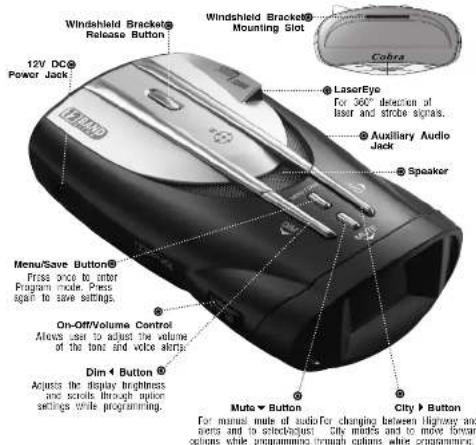
ExtremeBright DataGraffkDisplay @ Blue sunlight-readable, extremely bright display provides intuitive graphite interaction and alert screens.


English

Product_Features
Product Features
Congratulations! You've made a smart choice by purchasing an ultra high performance digital radar/laser detector from Cobra. Just look at some of the sophisticated features and capabilities your new unit includes:
Xtreme Range
Superheterodyne Technology With super-fast sweep circuitry, XRS provides extra detection range and the best possible advance warning to even the fastest radar guns.
Ultra Performance Provides advanced warning with extra detection range
Detection and Separate Alerts For radar signals (X, K, Ka and Ku) has with signal strength indicated), laser signals, Safety Alert signals, Strobe Ale signals, VG-2 signals, Spectre 1 signals
8-Point Compass Display direction of type
LaserEye For 360° detection of laser and strobe signals Instant-On Ready Detects radar guns with "instant-on" (very fast) speed monitoring capabilities
Pop Detection
Detects the latest super-fast radar guns of the instant-on or single-pulse type Voice or Tone Alert With adjustable volume
ExtremeBright DataGrafix™ Display With easy-to-read graphical user interface IntelliShield Highway/City Modes Reduces falsing in urban areas with Highway mode and three levels of City mode settings
Safety Alert
Traffic warning system distinguishes important safety alerts from other K band signals
Strobe Alert
Emergency vehicle warning system
Manual Mule or Auto Mule
A Mote to
A mute function which automatically reduces false alerts by sensing engine RPMs
SmartPower
A timed power saving function that
save your info's letter favetat Programming
User-friendly mode selection and
setting with visual guidance
Car Battery Voltage Display Car battery voltage can be shown continuously on the display
Car Battery Low Voltage Warning Provides an alert when the car battery voltage drops below 11.9 volts
Auxiliary Audio Jack
For external speaker connection
Mounting
Mounts easily on windshield or dashboard

WARNING Non-cashions of parts substitutions not approved by Crane Environmental Corporation may vary. FDP Rates and sold your authority to operate in a acquisition
Nothing Currns Currn to a Currns A3

Accessories Order Info
Ordering From U.S.A.
Call 773-889-3087 for pricing or visit www.cobra.com.
For Credit Card Orders
Call 773-889-3087 [Press one from the main menu] 8:00 a.m. to 6:00 p.m. Central Time.
Monday through Friday.
Make Check or Money Order Payable To
Cobra Electronics, Attn: Accessories Dept., 2500 West Coast Street, Chicago, IL 60707 LLC A
3000 West, Central Steel Chicago, 12 octor 8.3A
To Order Online
Please visit our website: www.coora.com
Item & Description
| 420-330-N-001 | Straight 12V Power Cord |
| 420-325-N-001 | Coiled 12V Power Cord |
| 545-159-N-001 | Wincsh and Mounting Bracket |
| GLP-26 | Dual Port Power Adapter |
Nothing comes close to a

missedustika

Contents
Introduction
Important Information . . . . . . . . . . . . . . . . . . . . . . . . . . . . . . . . . . . . . . . . . . . . . . . . . . . . . . . . . . .
Customer Assistance . . . . . . . . . . . . . . . . . . . . . . . . . . . . . . . . . . . . . . . . . . . . . . . . 20
Controls, Indicators, Pop Alert 20 Connections and Display 12 K-Pand Nutt 27
Connections and Display ..... A2 ... X Band Alert ..... Zu Product Features ..... A3 ... K. Bond Alert ..... 20
Product Features ....... As K Band Alert ....... 20 Overview Ku Zand Alert 20
Year Detector VG 2 Alert 20
Your Detector Installation VG-2 Alert .... 20 VG-8 Audio Mode 20
Getting Started Spectra 1 Alert 20
Povier On/Off Spectre 1 Audio Mode 21
Standby Screen Icons 7 Safety Alert 21
Display Brightness Control Detection
Display Timeout Signals Detected 21
IntelliShield Highway/City Modes . 8 Audio Alerts . . . . . . . . . . . . . . . . . . . . . . . . . . . . 21
Muting an Alert . . . . . . . . . . . . . . . . . . . . . . . . . . . . 21
Auxiliary Audio Jack 9 Instant-On Detection 25
EasySet Programming 10 Pop Detection 25
Program Flow Diagrams 12 Responding to Alerts 25
Settings .... Understanding Radar and Laser .. 26
User Settings . . . . . . . . . . . . . . . . . . . . . . . . . . . . . . . . . . . . . . . . 28
City Mode Default 14Specifications 29
IntellMute Mode 14 Warranty
Set Intelligence . . . . . . . . . . . . . . . . . . . . . . . . . . . . . . . . . . . . . . . . . . . . . . . . . . . . . . . . . . . . . . . . . . . . . . . . . . . . 1-Year Warranty .... 30
Auto Muts Moda 16 Customer Assistance Veins as Tons Moda 16
Voice of Tone Mode 1 Product Service 31
Compass Mode 10 Trademark Acknowledgement . . . 32 Set Compass
Set Domplass . . . . . . . . . . . . . . . . . . . . . . . . . . . . . . . . . . . . . . . . . . . . . . . . . . . . . . . . . . . . . . . . . . . . . . . . . . . . . . . . . . . . . . . 18. Optional Accessories ..... 33
Smart-Over Mode 10 Accessories Order Info 37 Customizable Display Colors 18
Customizable Display Colors...16 Dim Mode Default 18 Appendix - Menu Guides
Car, Batteries, Vollages User Programming 34
Display Mode Alert Programming 36
Car Battery Low
Voltage Warning 19
Restore Factory Settings . . . . 19
Introduction

Overview
This manual describes the simple steps for mounting, setting up and using your detector. It also provides helpful information about how radar and laser guns are used and how you can interpret the alerts you receive.
Before you begin your installation, please read the important information section on page A1 and use the descriptions and feature lists on pages A2 and A3 to become familiar with your new detector.
About Your Detector
Display
This detector's innovative new display provides more, easier-to-use information than any technology to date. Using an OLED (Organic Light Emitting Diode) screen, the display offers large graphical alerts to signals as they are detected. Do not be alarmed by the nearly blank display you see when you first turn the unit on. The detector will function and alerts will appear as signals are detected. You can also elect to turn on the built-in Compass, IntellMute and Car Voltage so that they appear during normal operation. The initial and startup screens are shown on page 6.
Programming
EasySet Programming lets you conveniently customize the operation of your detector by changing the settings. You may want to start using the detector with the factory settings and then make changes after you are more familiar with the unit.
About This Manual
Please take a moment to learn about some special features of this manual.
Modular Descriptions
Once the detector is in use, this manual can be used as a ready reference to individual topics as needed. Each topic is completely covered in its section and cross-references to related topics are included where appropriate.
Appendix
The appendix pages 34–36 provide quick reference charts on the programming features of your detector.

English

Installation
Installation
Where to Mount Your Unit
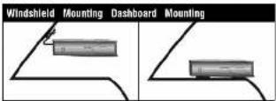
You will get optimum performance from your detector if you mount it at a point approximately in the center of the vehicle, as low as possible on the front windshield without obstructing the unit's view of the road either to the front or rear. You can also mount it directly on the dashboard.
The unit's lens must not be blocked and the LaserEye should have a clear view out the back window to allow 360° detection.
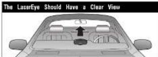
Radar and laser signals pass through glass but not through other materials and objects. Objects that can block or weaken incoming signals include:
■ Windshield wiper blades
■ Mirrored sun screens
■ Dark tinting at the top of the windshield
■ Heated windshields currently available on some vehicles (Instaclear for Ford, Electriclear for GM). Consult your dealer to see if you have this option.
Nothing Currns Currns to a Cofes 3

Windshield Mounting
| 1. Attach the nuber cups to the bracket. |  |
| 2. Make sure the rubber cups and your windshield are cl | |
| 3. Push the bracket firmly onto the windshield. | 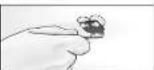 |
| 4. Attach the detector to the bracket. Check that the ur is parallel to the road's surface. | 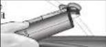 |
| 5. To adjust the angle if necessary, gently push or pull on the bracket to bot it. DO NOT use the elect to bend the bracket. | 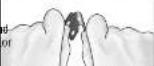 |
| 6. Plug the power cord into the detector. | 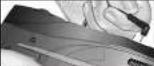 |
| 7. Plug the cigarette lighter adapter on the power cord into your vehicle's cigarette lighter. | 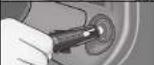 |

Installation
Dashboard Mounting
| 1. Place the detector on the dashboard to find a location where the unit has a clear view of the read and is parallel to the rack's surface. The angle CANNOT be adjusted after mounting. | |
| 2. Remove the paper back from one side or the hook and-loop fastener. | 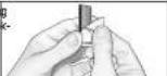 |
| 3. Attach the pad to the dashboard at your chosen location and remove the other paper backing. | 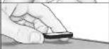 |
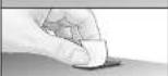 | |
| 4. Attach the detector to the hook-and-loop fastener. You can remove and reattach the unit as often as you like. | 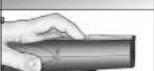 |
| 5. Plug the power cord into the detector. | 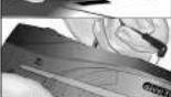 |
| 6. Plug the cigarette lighter adapter on the power cord into your vehicle's cigarette lighter. | 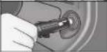 |


Getting Started
Power On/Off
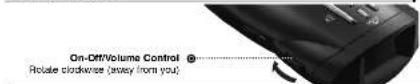
To Turn on the Unit and Adjust the Audio Volume
| Tone | Visual | Display | Voice |
| Testing, then three beeps | Cobra | Testing, then three beeps System Ready | |
| None | NE | Voice Alert | |
| Display changes to Display. Timeout after 30 seconds (battery default). | None None | ||

NOTE
When the system is first turned on from new, only the City or Highway icon will show on the screen because the Show Compass and IntelliMate functions are set to off at the factory. See pages 14 and 16 to turn these functions on.

NOTE
In some vehicles, power is supplied to the cigarette lighter even while the ignition is off. If this is the case with your vehicle and you have turned the SmartPower off, you should turn off or unplug your detector when parking for lengthy periods. Cobra recommends leaving SmartPower at the factory setting, which is on. See page 18.

English

Getting Started
Standby Screen Icons
Your detector uses the following icons to indicate modes and functions when set:
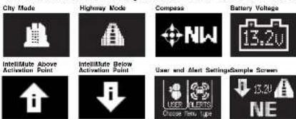
City Mode Highway Mode Compass Battery Voltage

For example, the sample screen indicates that IntelliMate is active. The Compass is calibrated, your system is set to Highway mode and your vehicle's battery voltage is charged to 13.2 volts.
Display Brightness Control
Your detector has a Bright display mode (for daytime driving)
and three levels of the Dim display mode:


NOTE
At the dark setting the
display will show a small dot
Dark to prevent all visual alerts from displaying moving back and forth
The factory setting is Dim. This level can be changed toward the bottom of the screen to indicate the unit in programming mode (see page 10.)
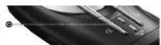
You can toggle between Bright and Dim modes by pressing the Dimbutton.

NOTE


English

Nothing Currns Currn to a Currs 7


Getting Started
DisplayTimeoutMode

Your detector has a Display Timeout mode to prolong the life of your screen. Touch any button to exit Display Timeout and recall the Standby screen.
The factory default is for Display Timeout to engage from the Standby screen after 30 seconds. You can change the time interval or deactivate Display Timeout in programming mode (see page 10).

In Display Timeout mode, the display will show a small dot moving slowly back and forth to indicate the unit is turned on.
IntelliShield Highway/City Modes
Your detector is equipped with IntelliShield false signal rejection technology which consists of a Highway mode and three different levels of City modes: City X, City X Beep Off and City X+K.
Highway mode provides full response to all signals detected. The City modes reduce false alerts while you are driving in or near urban areas where there are many sources for conflicting X or K band signals such as microwave towers and automatic door openers. The factory setting is Highway. The factory City mode default setting is City X; it can be changed in programming mode (see page 10).
You can toggle between Highway and City modes by pressing▶ballCity
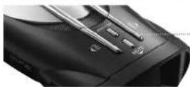
City ▶ Button
Press and release


When you change to City mode, the unit will enter whichever city default mode is set at the time.

English

Getting Started
Muting an Alert
Your detector allows you to quickly turn off an Audio Alert by momentarily pressing the Mute button. If you press the Mute button a second time during the alert, the Audio Alert will be turned back on. After the current alert is gone, the next alert will be heard.
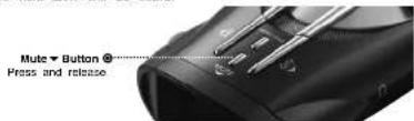
Two other features are incorporated in your detector to automatically mute or reduce the volume of alerts. See pages 14 and 16 for Intellmute and AutoMute modes.
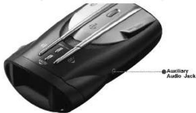
Auxiliary Audio Jack
The Auxiliary Audio Jack can be used to connect external speakers in environments with high ambient noise levels. The internal speaker will be disconnected. (This uses a mini stereo audio connector.)
Nothing Currns Currn to a Currns 9


EasySet Programming

EasySet Programming
EasySet Programming
EasySet Programming gives you quick and easy access to all the settings on your detector. It is used to program both:
■ User Settings (see pages 14 and 15)
User Programming Menu Guide (see pages 34 and 35).
■ Alert Settings (see page 20)
Alert Programming Menu Guide (see page 36).
Refer also to the Program Flow Diagrams for User Settings and Alert Settings programming to easily navigate to the setting you want to change (see pages 12 and 13). All settings are stored in memory when the power is turned off and will be recalled when the power is turned back on.

NOTE
You cannot enter Program mode during an alert. The unit will not detect signals while in Program mode. During programming, if no buttons are pressed for 15 seconds, the unit will automatically exit Program mode and save the most recent settings.
EasySet Programming Buttons:
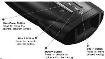

English
To use EasySel program mode:
- Press the Menu/Save button to reach the opening program screen.
- Choose whether you want to change:
a. User Settings — press the Dinton to enter the User Setting loop (see page 12)
b. Alert Settings — press the button to enter the Alert Setting loop (see page 13) - Press the Chyr Dim ◀ buttons to step forward or backward through the chosen settings loop until the desired option is reached.
NOTE
Press and release the button to move one option.
-
Press the Mule ▼ button to toggle the option on or off or to step through its multiple choices.
-
Repeat steps 3 and 4 to move to and set the next desired option(s).
-
Press the Menu/Save button when finished to save the settings and exit EasySet program mode. Or, simply wait 15 seconds without pressing any buttons.
NOTE
If power is turned off while in Program mode, option settings are saved to those in effect before Program mode was entered.
Nothing Currns Currn to a Currs 11


Program Flow Diagrams

Program Flow Diagrams
User Settings Programming
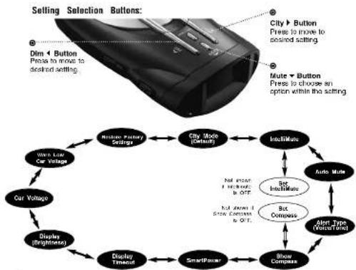
User Programming allows you to adjust the unit's display and sounds to your preferences. The User Settings can be selected using chendim City buttons by scrolling through the settings as shown in the program flow diagram below. The User Programming Menu Guide on page 34 is a handy reference showing the tone, visual display and voice prompts that accompany each setting. After selecting a setting, use the Muten to choose an option within the setting.

NOTE
When you choose User Settings (page 11, step 2a), the system displays whichever setting was last changed.
flowchart
graph TD
    A["Selling Selection Buttons"] --> B["Dim ◀ Button Press to move to desired setting"]
    A --> C["Mute ◀ Button Press to choose an option within the setting"]
    B --> D["Car Voltage"]
    C --> E["Display (Brightness)"]
    D --> F["Display Timeout"]
    E --> G["SmartPower"]
    F --> H["Auto Mode"]
    G --> I["Set Incidence"]
    H --> J["Set Compass"]
    I --> K["Show Compass"]
    J --> L["Alert Type (VoiceTrend)"]
    K --> M["Auto Mode"]
    L --> N["City Mode (Default)"]
    M --> O["Realizer Factory Settings"]
    N --> P["Realizer Factory Settings"]
    O --> Q["Realizer Factory Settings"]
    P --> R["Realizer Factory Settings"]
    Q --> S["Realizer Factory Settings"]
    R --> T["Realizer Factory Settings"]
    S --> U["Realizer Factory Settings"]
    T --> V["Realizer Factory Settings"]
    U --> W["Realizer Factory Settings"]

English
Alert Settings Programming
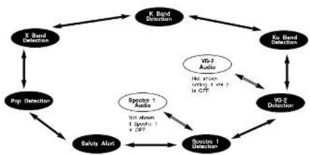
Alert Programming allows you to selectively turn on or off detection of some signals. The Alert Settings can be selected using the Dlm ◀ and City▶ buttons by scrolling through the settings as shown in the program flow diagram below. The Alert Programming Menu Guide on page 36 is a handy reference showing the tone, visual display and voice prompts that accompany each setting. After selecting a setting, use the Mute ▼ button to choose an option within the setting.

NOTE
When you choose Alert Settings (page 11, Step 2b), the system displays whichever setting was last changed.
flowchart
graph TD
    A["X Band Detection"] --> B["Pop Detection"]
    B --> C["Squote 1"]
    C --> D["Squote 1 Detection"]
    D --> E["Ve2 Audio"]
    E --> F["Ve2 Audio (Group 1 & Group 2) in GTF"]
    F --> G["Ve2 Audio (Group 2 & Group 3) in GTF"]
    G --> H["X Band Detection"]
    H --> I["K Band Detection"]
    I --> J["Ku Band Detection"]
    J --> K["Ve2 Detection"]
    K --> L["Squote 1"]
    L --> M["Squote 1 Detection"]
    M --> N["Squote 1"]
    N --> O["Squote 1"]
    O --> P["Squote 1"]
    P --> Q["Squote 1"]
    Q --> R["Squote 1"]
    R --> S["Squote 1"]
    S --> T["Squote 1"]
    T --> U["Squote 1"]
    U --> V["Squote 1"]
    V --> W["Squote 1"]
    W --> X["Squote 1"]
    X --> Y["Squote 1"]
    Y --> Z["Squote 1"]
    Z --> A
This detector allows you to customize its operation by changing settings in the User Programming and the Alert Programming modes. (See page 11 for entering the EasySet Programming mode.) Also, refer to the Appendix (pages 34-36) while programming. These show the lists of User and Alert settings. Features of the programmable settings are described on the following pages.
Nothing Currns Currn to a Currs 13

Settings
User Settings
IntelliShield City Mode Default
City Mode Default makes three levels of Audio Alert suppression available when you toggle from Highway to City mode (see page 8). The factory setting is City X.
City X sounds a single beep when an x band signal is first detected. The alert then sounds when signal strength reaches level 3.
City X+K combines the City X mode with prevention of K band audio alerts until the signal strength reaches level 2.
City X Beep Off blocks all X band audio alerts until the signal strength reaches level 3.
IntellMute Mode
IntelliMute is a unique feature that allows you to avoid alerts you don't need to hear because you are stopped or moving slowly. By sensing the "revs" (RPMs) of your engine, IntelliMute knows when you are at low speed and automatically mutes alerts (except for strobe signals from emergency vehicles). It works with all City and Auto Mute modes.
Before IntelliMute will work, you must set an activation point for your engine's revs (see page 15). Whenever the revs are below that point, IntelliMute will begin muting. The activation point will be stored in memory and recalled each time the power is turned on. The factory setting is IntelliMute off.
An IntelliMate icon will appear in the display when IntelliMate is on and activation is sat. Whenever engine revs are below the activation point, the arrow points down. When revs are above the activation point the arrow points up.
Above Activation Point

Below Activation Point

If, for any reason, the unit stops sensing your engine's revs. IntellMute will indicate an error and automatically turn off.

English

Settings

NOTE
IntellMute may not work with some vehicles because it cannot sense the engine's revs. In such cases, you can reduce unwanted audio alerts by using Auto Mute and City mode when appropriate.

NOTE

The rev point must be reset if you use your detector in a different vehicle.

NOTE When initially choosing your IntelliMute activation point, a setting of approximately 300 to 600 RPMs above idle is recommended. You can reset the activation point at any time to fit your individual preferences and driving style.

CAUTION
Do not attempt to set the row point while driving. Your vehicle should be parked and diving to avoid a collision during the process.
Set IntelliMute
After the detector is installed in your vehicle and the unit is turned on, advance through the User Settings Programming to the Set IntelliMute setup screen where the activation point can be set.
Setting the activation point progresses from the setup screen shown on the User Programming Menu Guide (see page 34). From that screen:
-
Press the Mutebutton to begin the setting process.
-
Press and hold the vehicle accelerator at the desired engine RPMs.
-
Press the Mutebutton to complete the setting process.
The system will store the engine RPM setting and provide a completion message on the display as well as a tone or voice message.

NOTE
If the unit is unable to sense usable pulses within three seconds or if you do not set a rev point within 30 seconds of beginning the setup, IntellMute will indicate an error. If you do not try again within five seconds, it will automatically turn off. The unit will provide corresponding messages for these conditions.
Once an activation point has been set, you can easily change it by going directly to Set IntelliMute in User Settings Programming and repeating the three-step setup process.
Nothing Currns Currn to a Currs 15


Settings
Auto Mute Mode
When Auto Mute is on, it automatically reduces the audio volume of all alerts after they have sounded for four seconds. The signals will remain muted for as long as the signal is detected. When Auto Mute is off, the alerts will sound at full volume for as long as the signal is detected. The factory setting for Auto Mute is on.
Voice or Tone Mode
You can set your detector to sound alerts and confirm program settings with either a Voice or a Tone Alert. Voice Alert provides voice messages in addition to tones. Tone Alert provides tones only. The factory setting is Voice Alert.
Compass Mode
Your detector includes an internal 8-point Compass that
can continuously display your current direction
N, NE, E, SE, S, SW, W, or NW.
BeforetheCompasswillwork, itmustbe
calibrated(see page 17). Calibration allows the Compass electronics to measure and store information about the magnetic fields generated by your vehicle so direction indications will be accurate. The factory setting is Compass off.
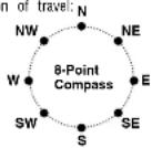
A Compass Icon and directional heading will appear in the display when the Compass is on and calibrated.
The Compass will remain accurately calibrated as long as your detector is mounted in the same place in your vehicle. If you change the location where the unit is mounted or move it to another vehicle, you must recalibrate the Compass. You should also recalibrate the Compass if you suspect it is providing inaccurate directions.
The Compass temporarily may not provide accurate readings if you are inside a building or enclosure, or are close to a large metal tractor/trailer, truck, or train. Once you are away from such a location, the Compass will work correctly again.

English

2.1.1 2017年
Set Compass
After the detector is installed in your vehicle and Compass is turned on (see page 34), the system will automatically advance to the Set Compass calibration screen from which the calibration can be performed.

WARNING
Before calibrating the Compass, go to a large parking lot or other safe, low-traffic area.

NOTE
When the instructions direct you to drive in two circles, make two complete loops (in either direction) from any starting orientation at any convenient speed. The loops need not be perfect and can be circles, small squares, four three-point turns, or any pattern that makes at least two complete turns within two minutes of starting the maneuver.
Calibrating the Compass progresses from the Calibrate Compass screen shown on the User Programming Menu Guide (see page 34). From that screen:
-
Press the Muhebutton to advance to the Compass screen.
-
Drive your vehicle in two circles.
-
Press the Mutebutton to complete the setting process.
The system will store the calibration data and provide a completion message on the display as well as a tone or voice message.

NOTE
If you do not press the Mule button within two minutes after beginning the Set Compass process, Compass calibration will automatically terminate. The unit will provide a corresponding message.
Once the initial calibration is complete, you can go to Set Compass in User Settings Programming and recalibrate the Compass as needed by repeating the three-step calibration process.


Settings
SmartPower Mode
Your detector includes the SmartPower feature that, when turned on, will put the unit into Standby mode (low power) 15 minutes after the car's engine has been turned off.
Before SmartPower enters Standby mode, you will hear three beeps and SmartPower will flash on the display. To return the unit to normal Power mode and exit Standby mode, start the car, press any button or turn the unit off and then on again. The factory setting is SmartPower on.
SmartPower Entering Standby Mode (Flashing)
SMART POWER
Display Timeout
Display timeout determines how long the Standby screen is illuminated before switching the unit to Dark. The factory default is 30 seconds. You can set the time interval to 15 seconds, 30 seconds, one minute, three minutes, or Always On (see User Settings Programming described on page 12).
Dim Mode Default (Display Brightness)
You can set the default level for the Dim mode (Dim, Dimmer or Dark) as discussed in the Display Brightness Control section on page 7. The factory setting is Dim.

Settings
Car Battery Voltage Display Mode
Your detector can sense your vehicle's electrical system voltage (Car Battery Voltage) and show it on the display during normal operation of the unit. The factory setting is Car Battery Voltage on.
Car Battery Low Voltage Warning
In addition to displaying system voltage, your detector can provide a warning that battery voltage is low so that timely steps can be taken to correct the problem. The Car Battery Low alert is triggered when the voltage drops below 11.9 volts. Following the alert, the unit enters SmartPower mode to avoid further draining your car battery (see page 18). The factory setting is Car Battery Low off.
From the Restore Factory Settings screen, you can quickly and conveniently restore your detector to its original settings. Confirmation messages are provided during the process.

English
Nothing Currns Currn to a Currs 19

Settings

Detection
Alert Settings
Pop Alert
When Pop Detect mode is on, Pop radar signals will be detected and an alert will be given. During the alert, the unit will continue to detect other signals. The factory setting is Pop Detect off.
X Band Alert
When X Band Detect mode is on, X Band radar signals will be detected and an alert will be given. During the alert, the unit will continue to detect other signals. The factory setting is X Band Detect on.
K Band Alert
When K Band Detect mode is on, K Band radar signals will be detected and an alert will be given. During the alert, the unit will continue to detect other signals. The factory setting is K Band Detect on.
Ku Band Alert
When Ku Band Detect mode is on, Ku Band radar signals will be detected and an alert will be given. During the alert, the unit will continue to detect other signals. The factory setting is Ku Band Detect off.
VG-2 Alert
The detector is undetectable by VG-2 detection devices and can alert you when such a device is in use near your vehicle. When VG-2 Detect mode is on, VG-2 signals will be detected and an alert will be given. During the alert, the unit will continue to detect other signals. The factory setting is VG-2 Detect off.
VG-2 Audio Mode
When VG-2 Audio mode is on, alerts will be sounded as well as being displayed on the screen. This setting is only available if VG-2 Alert is on. The factory setting is VG-2 Audio off.
Spectre 1 Alert
The detector is undetectable by Spectre 1 detection devices and can alert you when such a device is in use near your vehicle. When Spectre 1 Detect mode is on, Spectre 1 signals will be detected and an alert will be given. During the alert, the unit will continue to detect other signals. The factory setting is Spectre 1 Detect off.

English
Spectre 1 Audio Mode
When Spectre 1 Audio mode is on, alerts will be sounded as well as being displayed on the screen. This setting is only available if Spectre 1 Alert is on. The factory setting is Spectre 1 Audio off.
Safety Alert
When Safety Alert mode is on, Safety Alert radar signals will be detected and an alert will be given. During the alert, the unit will continue to detect other signals. The factory setting is Safety Alert on.
Detection
Signals Detected
The tables on the following pages show the types of Signals your detector will detect, as well as the visual alerts it provides for each of them.
Audio Alerts
A distinctly different Alert tone is used for each type of signal detected (including separate tones for each laser signal). For X, K, Ka and Ku band radar signals, the tones will repeat faster as you approach the signal source. The repeat rate of the tones gives you useful information about the signal detected. See responding to alerts on page 25.
Visual Display
An Indication of the type of signal detected will appear in the OLED Data Display. During X, K, Ka and Ku alerts, you will also see the numbers from one to five, indicating the strength of the signal detected.
Nothing Curves Close to a Cofes 21
Detection
Signal Strength Chart
Signal Strength = 1
Signal Strength = 2
Signal Strength = 3
Signal Strength = 4
Signal Strength = 5


(Weakest Signal)
(Strongest Signal)
Radar Signals and Visual Displays
| Type of Signal Visual Display Voice | ||
| X Band Radar X | Alert | |
| RADARX1 | ||
| K Band Radar K | Alert | |
| RADARK2 | ||
| Ka Band Radar Ka | Alert | |
| RADARKa3 | ||
| Ku Band Radar Ku | Alert | |
| RADARKu4 | ||
| Pop Radar Mode Pop | Alert | |
| RADARPOP | ||

English

Detection
Laser Signals and Visual Displays
| Type of Signal Visual Display Voice | ||
| LTI 20-20* Laser Alert | ||
| 20/20 | ||
| LTI Ultra-Lyte* Laser Alert | ||
| ULTRA LYTE | ||
| Kustone Signals ProLaser* | PRO LASER | Laser Alert |
| Kustone Signals ProLaser III* | PRO LASER 3 | Laser Alert |
* Your detector provides 360 detection of these signals.

NOTE
Beep rate changes with different laser alerts.
Strobe Alert Signals and Visual Displays
| Type of Signal Visual Display Voice | ||
| 3M Opticom or Tomar* | Emergency Vehicle Approaching | |
| EMERGENCY*EV* | ||
Your detector provides 360 detection of these signals.
Nothing Come to a Cofes 23

Your De

Detection
Safety Alert Signals and Visual Displays
| Type of Signal Visual Display Voice | ||
| Emergency Vehicles | Emergency Vehicle EMERGENCY EV | Approaching |
| Road Hazards Road | Hazard Ahead ROAD HAZARD RH | |
| Trains Train Approaching | ||
| RAILROAD RR | ||

NOTE
are different tones for each Safety Alert.
VG-2 and Spectre 1 Alert Signals and Visual Displays
| Type of Signal Visual Display Voice | ||
| VG-2 Alert VG-2 Alert | ||
| RADARVG2 | ||
| Spectre 1 Spectre | Alert | |
| RADARSP1 | ||

NOTE
There are different tones for each alert.

English

Detection
Instant-On Detection
Your detector is designed to detect Instant-On speed monitoring signals, which can suddenly appear at full strength.
NOTE
You should take appropriate action immediately whenever an instant-on alert is given.
Pop Detection
Your detector is designed to detect single pulse mode radars. These radars are designed to have a low probability of detection. You should note that these radar puns have a much shorter range while in this mode.
Responding to Alerts
| Description Interpretation | Recommended Response | |
| Tone repeats slowly at first, then specks up rapidly. | Probably police nadar. FULL ALERT | |
| Tone sounds one time only. | Probably a false alarm, but possibly pushed nadar, Spectre 1 or VG-2 mercy. | Exercise caution |
| Tone instantly begins repeating rapidly. | Rocar, Spectre 1 or VG-2 nadar has been activated suddenly. | FULL ALERT |
| Pop mode tone. | Pop mode gun very close. | FULL ALERT |
| Tone repeats slowly as you approach a hill or bridge, then specks up simply as you reach it. | Probably police nadar beyond the hill or bridge. | FULL ALERT |
| Tone repeats slowly for a short period. | Probably a false alarm. | Exercise caution |
| Any type of laser alert. | Laser alerts are never false alarms. | FULL ALERT |
| Any Safety Alert or Stroo Alert. | You are meaning an emergent vehicle, railroad dressing, or road hazard (construction, accident, etc.). | Exercise caution |
Nothing Currns Currn to a Currns 25

Understanding Radar and Laser

Understanding Radar and Laser
Understanding Radar and Laser
Radar Speed Monitoring Systems
Three band frequencies have been approved by the Federal Communications Commission (FCC) for use by speed monitoring radar equipment:
X band 10.525 GHz
K band 24.150 GHz
Ka band 33.400 - 36.00 GHz
Your detector detects signals in all three radar bands, plus Ku band (13.435 GHz), which is an approved frequency used in parts of Europe and Asia.
VG-2 and Spectre 1
VG-2 and Spectre 1 are "detector detectors" that work by detecting low-level signals emitted by most radar detectors. Your detector does not emit signals that can be detected by VG-2 or Spectre 1, but does detect VG-2 and Spectre 1 signals and will alert you when a device is in use near your vehicle, if you so choose.
Safety Alert Traffic Warning System SAFETY ALERT
FCC-approved Safety Alert transmitters emit microwave radar signals that indicate the presence of a safety-related concern. Depending on the frequency of the signal emitted, it can indicate a speeding emergency vehicle or train, or a stationary road hazard.
Because these microwave signals are within the K band frequency, most conventional radar detectors will detect Safety Alert signals as standard K band radar. Your detector, however, is designed to differentiate between standard K band and Safety Alert signals, and give separate alerts for each.
Safety Alert technology is relatively new. Safety Alert transmitters can be found in limited numbers in all 50 states, but the number is growing. Depending on your location, you may not receive these alerts regularly and may often encounter emergency vehicles, trains and road hazards without being alerted. As the number of transmitters increases, these alerts will become more common.
When you receive such an alert, please watch for emergency vehicles ahead of you, on cross streets and behind you. If you see an emergency vehicle approaching, please pull over to the right side of the road and allow it to pass.

English
Strobe Alert
Special strobes mounted on the light bars of authorized emergency vehicles (fire trucks, police cars, ambulances) automatically change traffic signals as the vehicle approaches an intersection. These strobes and the special strobe detectors located on the traffic signals, introduced fairly recently by 3M and Tomar, are already in use in more than 1000 cities nationwide. Cobra's exclusive Strobe Alert detector will detect these special strobes and give an emergency vehicle alert.
When you receive such an alert, please watch for an approaching emergency vehicle and pull over to allow it to pass. To inquire about coverage in your area, contact your local fire and police departments.
LIDAR (Laser)
The correct name for the technology that most people refer to as laser is actually LIDAR, which stands for Light Detection and Ranging. LIDAR operates much like radar. Its signal spreads out like a radar signal, though not as widely. Unlike radar, LIDAR must have a clear line of sight to its target vehicle throughout the entire measurement interval. Obstructions such as sign posts, utility poles, tree branches, etc., will prevent valid speed measurement.
Some common questions about LIDAR include:
■ Does weather have any affect on LIDAR?
Yes. Rain, snow, smoke, fog, or airborne dust particles will reduce the effective range of LIDAR and can, if dense enough, prevent its operation.
■ Can LIDAR operate through glass?
Yes. Newer LIDAR guns can obtain readings through most types of glass. However, the laser pulse also can be received through glass to trigger an alarm by your detector.
■ Can LIDAR operate while in motion?
No. Because LIDAR operates by line of sight, the person using it cannot drive the vehicle, aim and operate the gun all at the same time.
■ Is LIDAR legal to use?
Yes. It is legal in all 50 states.
Nothing Curves Cross to a Cofes 27


Maintenance

Specifications
Pop Radar Guns
The Pop mode Radar Gun is a single pulse Doppler radar that is a feature of a K and Ka (Bee III Ka radar gun) band Instant-On radar gun. It uses a single short time pulse to measure the target vehicle's speed. Despite the fact that the short, single pulse makes the unit very sensitive to officer hand and vehicle movement and reduces the range of the gun in Pop mode to 50% of its range in Continuous Wave mode, this feature is added in an attempt to make the radar gun invisible to Radar Detectors.
Although your detector can sense Pop signals beyond the effective range of Pop radar guns, there will be a signal to sense only if a gun is triggered. In addition, the Pop mode receiver section is more prone to false alerts because of its extra sensitivity. This is especially so in urban areas. As a result, you should consider using the Pop Detect mode only in highway and rural situations. Cobra Electronics has included a user selectable on or off Pop Detect mode.
Maintenance
Maintenance of Your Radar Detector
Your detector is designed and built to give you years of trouble-free performance without the need for service. No routine Maintenance is required.
If your unit does not appear to be operating properly, please follow these troubleshooting steps:
■ Make sure the power cord is properly connected.
■ Make sure the socket of your vehicle's cigarette lighter is clean and free of corrosion.
■ Make sure the power cord's cigarette lighter adapter is firmly seated in your cigarette lighter.
- Check the power cord fuse. (Unscrew the ribbed end cap of the cigarette lighter adapter and examine the fuse. If required, replace it with a 2-amp fuse only.)
Specifications
Band and Frequencies
| Band Frequencies | |||
| X Band 10.525 ± 0.050 GHz | |||
| K Band 24.125 ± 0.125 GHz | |||
| Safety Alert 24.070 ± 0.010 GHz | |||
| Traffic Warning System | 24.110 ± 0.010 GHz | ||
| 24.190 ± 0.010 GHz | |||
| 24.230 ± 0.010 GHz | |||
| Ka Band 34.700 ± 1.300 GHz | |||
| Ku Band 13.435 ± 0.050 GHz | |||
| VG-2 11.500 ± 0.250 GHz | |||
| Spectra 1 13.300 ± 0.200 GHz | |||
| Laser | 910 | ± 50 | nm |
| Strobe | 730 | ± 300 | nm |
This radar detector is covered by one or more of the following U.S. patents: 5,497,148; 5,594,432; 5,612,685; 6,078,279; 6,094,148; 6,621,447. Additional patents may be listed inside the product or pending.

English
Nothing Currick Gown to a Cattle 29


Warranty

Product Service
Limited 1-Year Warranty
For Products Purchased in the U.S.A.
Cobra Electronics Corporation warrants that its Cobra 12 Band Radar/Laser Detectors, and the component parts thereof, will be free of defects in workmanship and materials for period of one year from the date of first consumer purchase. This warranty may be enforced by the first consumer purchaser, provided that the product is utilized within the U.S.A.
Cobra will, without charge, repair or replace, at its option, defective 12 Band Radar/Lasar Detectors, products or component parts upon delivery to the Cobra Factory Service Department, accompanied by proof of the date of first consumer purchase, such as a duplicated copy of a sales receipt.
You must pay any initial shipping charges required to ship the product for warranty service, but the return charges will be at Cobra's expense, if the product is repaired or replaced under warranty.
This warranty gives you specific rights, and you may also have other rights which vary from state to state.
Exclusions: This limited warranty does not apply:
-
To any product damaged by accident.
-
In the event of misuse or abuse of the product or as a result of unauthorized alterations or repairs.
-
If the serial number has been altered, defaced or removed.
-
If the owner of the product resides outside the U.S.A.
All implied warranties, including warranties of merchantability and fitness for a particular purpose are limited in duration to the length of this warranty.
Cobra shall not be liable for any incidental, consequential or other damages including, without limitation, damages resulting from loss of use or cost of installation.
Some states do not allow limitations on how long an implied warranty lasts and/or do not allow the exclusion or limitation of incidental or consequential damages, so the above limitations may not apply to you.
Product Service
For any questions about operating or installing this new Cobra product, or if parts are missing...PLEASE CALL COBRA FIRST...do not return this product to the store. See customer assistance on page A1.
If this product should require factory service, please call Cobra before sending the product. This will ensure the fastest turn-around time on any repair. If Cobra asks that the product be sent to its factory, the following must be furnished to have the product serviced and returned:
-
For Warranty Repair include some form of proof-of-purchase, such as a mechanical reproduction or carbon of a sales receipt. Make sure the date of purchase and product model number are clearly readable. If the originals are sent, they cannot be returned;
-
Send the entire product
- Enclose a description of what is happening with the product. Include a typed or clearly printed name and address of where the product is to be returned, with phone number (required for shipment).
- Pack product securely to prevent damage in transit. If possible, use the original packing material;
- Ship prepaid and insured by way of a traceable carrier such as United Parcel Service (UPS) or Priority Mail to avoid loss In transit to: Cobra Factory Service Cobra Electronics Corporation 6500 West Cortland Street Chicago, Illinois 60707 U.S.A.;
- If the product is in warranty, upon receipt of the product it will either be repaired or exchanged depending on the model. Please allow approximately 3 - 4 weeks before contacting Cobra for status. If the product is out of warranty, a letter will automatically be sent with information as to the repair charge or replacement charge.
For any questions, please call 773-889-3087 for assistance.

English
Nothing Curves Cross to a Cofes 31

Trademark Acknowledgement

Accessories
Trademark Acknowledgement
Cobra, DigiView, EasySet, Extra Sensory Detection IntelliMuté, IntelliShield, LaserEye, Nothing Comes Close to a CobraSafety Alert Traffic Warning System, Strobe Alert VG-2 Alert Xtreme Range Superheterodyne and the snake design are registered trademarks of Cobra Electronics Corporation, USA.
Cobra Electronics Corporation™, 12 Band™, ExtremeBright DataGrafix™, IntelliLink™, Revolution™ Series, SmartPower™, Spectre Alert™, Super-Xtreme Range Superheterodyne™, S-XRS™, UltraBright™, and Voice Alert™ are trademarks of Cobra Electronics Corporation, USA.
Opticom™ is a trademark of 3M Corporation. InstabineFord is a registered trademark of Ford Motor Company, Inc. Electricizer GM is a registered trademark of General Motors Corporation, 20-20™ and Ultra-Lyte™ are trademarks of Laser Technology, Inc. ProLaser™ and ProLaser III™ are trademarks of Kustom Signals, Inc. Bee III™ and Pop™ are a trademarks of MPH Industries. Spectre™ is a trademark of Stalcar. Interceptor VG-2™ is a trademark of TechniSonic Industries LTD. Tamar registered trademark of TOMAR Electronics, Inc.
Optional Accessories
You can find quality Cobra products and accessories at your local Cobra dealer, or in the U.S.A., you can order directly from Cobra. See order info on page 37.
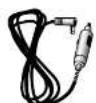
Straight 12V DC Power Cord
Includes plug and fuse Item # 420-030-N-001

Windshield Mounting Bracket
Includes suction cups Item # 545-159-N-001
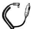
Coiled 12V DC Power Cord
Includes plug and fuse Item # 420-026-N-D01
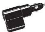
Dual Port Power Adapter
Includes adjustable plug (up to 90°) and fuse Item ♦ CLP-28

English
Nothing Currns Currn to a Currns 33
Appendix

Appendix
User Programming Menu Guide
| Mode Tone | Visual Display | Voice | |
| Set IntelliShield City mode defaultPage 14 | Two beeps | CITY MODEX ONLY | City X |
| Orc beep | CITY MODEX + K | CityX, K | |
| One beep | CITY MODENO BEEP | City XBoep Off | |
| Set IntelliMute modePage 15 | Two beeps | INTELLIMUTEOFF | IntelliMute Off |
| Orc beep | INTELLIMUTEON | IntelliMute On | |
| Set IntelliMute setup*Page 16 | Two beeps | INTELLIMUTESETUPPressTo Begin | Set Engine Reys |
Not shown if IntellMute is off. Complete instructions for IntellMute setup are shown on the referenced page.
| Mode Tone | Visual Display | Voice | |
| Set AutoMute mode | Two beeps | AUTO MUTE ON | Auto Mute On |
| Page 16 | One beep | AUTO MUTE OFF | Auto Mute Off |
| Set Voice or Tone mode | None Voice | ALERT TYPE VOICE | Alert |
| Page 16 | None | ALERT TYPE TONE | Tone Alert |
| Set Compass mode | Two beeps | SHOW COMPASS OFF | Compass Off |
| Page 17 | One beep | SHOW COMPASS ON | Compass On |
| Set Compass** Page 17 | Two beeps | CALIBRATE COMPASS Press Drive 2 circles. | Set Compass |
** Not shown if Compass is all. Complete Instructions for calibrating the Compass are shown on the referenced page and on the separate insert.

NOTE
Factory defaults are highlighted in light gray. See referenced pages for more information on the modes

English

Appendix
User Programming Menu Guide (continued)
| Mode | Tone | Visual Display | Voice |
| Set Smart-Power modePage 18 | Two beeps | SMART POWER ON | Smart Power On |
| One beep | SMART POWER OFF | Smart Power Off | |
| Set Display Timeout IntervalPage 18 | One beep | DISPLAY TIMEOUT 15 SEC | None |
| One beep | ADJUST TIMEOUT 15 SEC | None | |
| One beep | ADJUST TIMEOUT 30 SEC | None | |
| One beep | ADJUST TIMEOUT 1 MIN | None | |
| One beep | ADJUST TIMEOUT 3 MIN | None | |
| One beep | ADJUST TIMEOUT ALWAYS ON | None | |
| Set Display Dim mode defaultPage 18 | One beep | DISPLAY DIMMER | Dimmer |
| One beep | DISPLAY DARK | Dark |
| Mode | Tone | Visual Display | Voice |
| Set car battery voltage display modePage 19 | Two beeps | CAR VOLTAGE13.9V OFF | Display Car Voltage Off |
| One bopp | CAR VOLTAGE13.9V ON | Display Car Voltage On | |
| Set battery low car voltage warningPage 19 | Two beeps | WARN LOW CAR VOLTAGE OFF | Car Voltage Warning Off |
| One bopp | WARN LOW CAR VOLTAGE ON | Car Voltage Warning On | |
| Restore factory settingsPage 18 | Two bocors | RESTORE FACTORY SETTINGS | Restore Factory Settings |

NOTE Factory defaults are highlighted in light gray. See referenced pages for more information on the modes.


Appendix
Alert Programming Menu Guide
| Mode | Tone | Visual Display | Voice |
| Set Pop Detect mode | Two beeps | POP DETECTION OFF | Pop On |
| Page 20 | One beep | POP DETECTION ON | Pop On |
| Set X Band Detect mode | Oro beep | X BAND DETECTION ON | X On |
| Page 20 | Oro beep | X BAND DETECTION OFF | X Off |
| Set K Band detect mode | Two beeps | K BAND DETECTION ON | K On |
| Page 20 | One beep | K BAND DETECTION OFF | K Off |
| Set Ku Band Detect mode | Two beeps | Ku BAND DETECTION ON | Ku On |
| Page 20 | Oro beep | Ku BAND DETECTION OFF | Ku Off |
| Set VG-2 Detect mode | Two beeps | VG-2 DETECTION ON | VG-2 On |
| Page 20 | Oro beep | VG-2 DETECTION OFF | VG-2 Off |
| Mode | Tone | Visual Display | Voice |
| Set VG-2 Audio mode* | Two beeps | VG-2 Audio ON | VG-2 Audio On |
| Page 20 | One beep | VG-2 Audio OFF | VG-2 Audio ON |
| Set Spectre 1 Detect mode | Two beeps | SPECTRE 1 DETECTION ON | Spectre On |
| Page 20 | One beep | SPECTRE 1 DETECTION OFF | Spectre Off |
| Set Spectre 1 Audio mode** | Two beeps | SPECTRE 1 AUDIO ON | Spectre Audio On |
| Page 21 | One beep | SPECTRE 1 AUDIO OFF | Spectre Audio ON |
| Set Safety Alert mode | Two beeps | SAFETY ALERT ON | Safety Alert On |
| Page 21 | One beep | SAFETY ALERT OFF | Safety Alert On |
* Not shown II VG-2 Detect is off.
** Not shown if Specire 1 (Select) is off

NOTE
Factory defaults are highlighted in
light gray. See referenced pages for
more information on the modes.
Nothing comes close to a Cohne 36
- The Cobralineofqualityproductsincludes:
- ImportantInformationand CustomerAssistance
- Important Information
- Customer Assistance
- Product Features
- Xtreme Range
- Pop Detection
- Safety Alert
- Strobe Alert
- A Mote to
- Auxiliary Audio Jack
- Mounting
- Ordering From U.S.A.
- For Credit Card Orders
- Monday through Friday.
- To Order Online
- Contents
- Introduction
- Overview
- About Your Detector
- Display
- Programming
- About This Manual
- Modular Descriptions
- Appendix
- Installation
- Where to Mount Your Unit
- Windshield Mounting
- Dashboard Mounting
- Getting Started
- NOTE
- English
- Standby Screen Icons
- Display Brightness Control
- DisplayTimeoutMode
- IntelliShield Highway/City Modes
- Muting an Alert
- EasySet Programming
- To use EasySel program mode:
- Program Flow Diagrams
- User Settings Programming
- Alert Settings Programming
- User Settings
- IntelliShield City Mode Default
- IntellMute Mode
- Set IntelliMute
- Settings
- Auto Mute Mode
- Voice or Tone Mode
- Compass Mode
- BeforetheCompasswillwork, itmustbe
- Set Compass
- WARNING
- SmartPower Mode
- Display Timeout
- Dim Mode Default (Display Brightness)
- Car Battery Voltage Display Mode
- Car Battery Low Voltage Warning
- Detection
- Alert Settings
- Pop Alert
- X Band Alert
- K Band Alert
- Ku Band Alert
- VG-2 Alert
- VG-2 Audio Mode
- Spectre 1 Alert
- Spectre 1 Audio Mode
- Signals Detected
- Audio Alerts
- Visual Display
- Instant-On Detection
- Understanding Radar and Laser
- Radar Speed Monitoring Systems
- VG-2 and Spectre 1
- Safety Alert Traffic Warning System SAFETY ALERT
- LIDAR (Laser)
- Some common questions about LIDAR include:
- Maintenance
- Specifications
- Pop Radar Guns
- Maintenance of Your Radar Detector
- Warranty
- Product Service
- Limited 1-Year Warranty
- For Products Purchased in the U.S.A.
- Exclusions: This limited warranty does not apply:
- Trademark Acknowledgement
- Accessories
- Optional Accessories
Brand : COBRA
Model : XRS 969
Category : Gps