Bandpass BPS6 TL - Subwoofer SONANCE - Free user manual and instructions
Find the device manual for free Bandpass BPS6 TL SONANCE in PDF.


| Product Type | Bandpass Subwoofer |
| Brand | Sonance |
| Model | Bandpass BPS6 TL |
| Series | Architectural Series |
| Enclosure Type | Bandpass (ported) |
| Woofer Size | 6 inches |
| Mounting Type | In-wall / In-ceiling (stud or joist) |
| Mounting Hardware Included | 4 lag screws (5/16" x 3"), 4 washers, cardboard template |
| Port Tube | Removable foam plug (discard), 90-degree connector with clamp ring |
| Speaker Wire Connection | 4-conductor, positive to red, negative to black, zip tie included |
| Signal Test Requirement | 60 seconds with amplified program material |
| Installation Distance | 15" from front edge of subwoofer to center of connector |
| Hose Length Adjustment | Can be shortened up to 3 inches (do not extend) |
| Drill Hole Size | 1/4" (6mm) for mounting screws |
| Compatible Stud Bay | 2x4 stud or joist |
| Accessories Included | Quickstart Guide, port tube, mounting template, hardware |
| Care & Maintenance | Wipe with dry cloth; avoid moisture and solvents |
| Safety | Ensure secure mounting to prevent falling; avoid electrical hazards |
| Spare Parts Availability | Contact Sonance customer support for replacement parts |
| Repairability | Service by qualified technician; no user-serviceable parts |
Frequently Asked Questions - Bandpass BPS6 TL SONANCE
User questions about Bandpass BPS6 TL SONANCE
0 question about this device. Answer the ones you know or ask your own.
Ask a new question about this device
Download the instructions for your Subwoofer in PDF format for free! Find your manual Bandpass BPS6 TL - SONANCE and take your electronic device back in hand. On this page are published all the documents necessary for the use of your device. Bandpass BPS6 TL by SONANCE.
USER MANUAL Bandpass BPS6 TL SONANCE
BANDPASS SUBWOOFER THINLINE (AS)
BPS6 TL QUICKSTART GUIDE FOR USE WITH ARCHITECTURAL SERIES BANDPASS CONNECTORS

Box Contents
(1) Quickstart Guide
(1) Bandpass Subwoofer with port tube
(1) Cardboard mounting template
MOUNTING SCREWS & WASHERS:
(4) 5/16" x 3" lag screws
(4) 5/16" washers
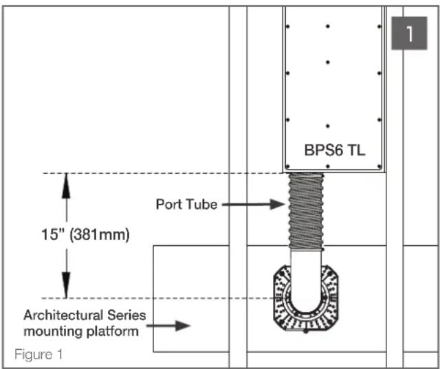
Determine the location of the mounting platform and subwoofer. Ensure there is adequate space to accommodate the subwoofer and port tube within the 2 x 4 stud bay or joist, allowing 15" from the front edge of the BPS6 TL to the center of connector. (See Figure 1).
NOTE: IF IT IS NOT POSSIBLE TO LOCATE THE BPS6 TL SUBWOOFER 15" AWAY FROM THE 90 DEGREE CONNECTOR OF THE MOUNTING PLATFORM, EXTRA HOSE MATERIAL (UP TO 3") MAY BE REMOVED. WHILE IT IS OKAY TO SHORTEN THE HOSE, NEVER EXTEND THE HOSE LENGTH.
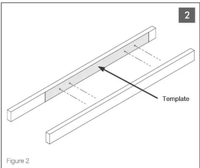
Place the subwoofer mounting template on the side of a 2 x 4 stud or joist and drill four 1/4" (6mm) holes through the stud at the locations shown on the mounting template. (See Figure 2).
NOTE: DRILLING FROM THE INSIDE OF THE STUD BAY IS RECOMMENDED TO ENSURE THAT THE HOLE LOCATIONS MATCH THE SUBWOOFER SCREW LOCATIONS. (SEE FIGURE 2)
NOTE: BE SURE THAT THE SUBWOOFER TEMPLATE IS FLUSH WITH THE EDGE OF THE STUD OR SLIGHTLY RECESSED.
natural_image
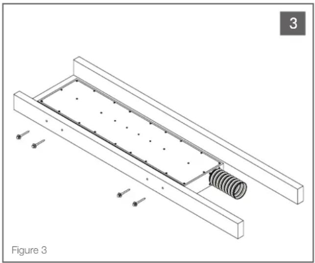
Technical line drawing of a mechanical assembly with spring and bolts, labeled Figure 3 (no text or symbols on the diagram itself)Hold the side of the BPS6 TL Subwoofer with the rubber damping pad up against the side of the stud or joist and install the four lag screws and washers to secure the BPS6 TL Subwoofer in place. (See Figure 3).
natural_image
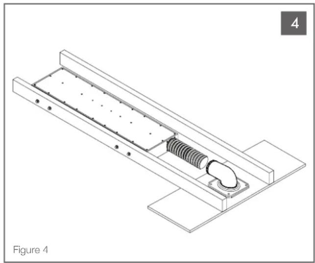
Technical line drawing of a mechanical assembly with spring and mounting base (no text or symbols)Prepare to attach the mounting platform to the stud or joist. Position the platform with the 90 degree connector pointed in the direction of the BPS6 TL port tube. (See Figure 4).
natural_image
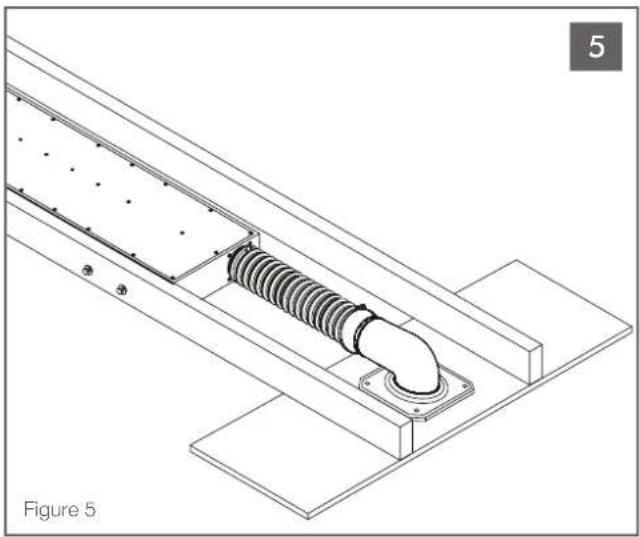
Technical line drawing of a mechanical assembly with threaded component and mounting brackets (no text or symbols)The BPS6 TL ships with a foam plug and tether inserted into the end of the port tube; remove and discard.
Guide the port tube onto the 90 degree connector so the tube is positioned snugly in place. Tighten the clamp ring to secure the port tube.
(See Figure 5).
Attach the mounting platform to the stud or joist. For mounting platform installation details visit www.sonance.com/in-wall-in-ceiling/architectural-series/bps6-tl.
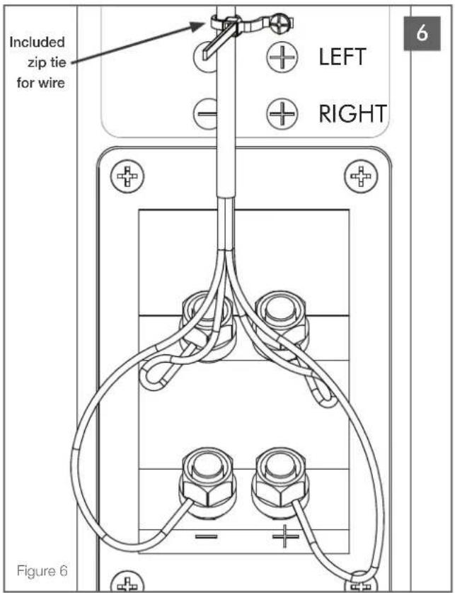
Attach the four conductor speaker wire to the input terminals; positive wires to red terminals and negative wires to black terminals. Run a signal test using an amplified program material for at least 60 seconds. Secure the speaker wire to the zip tie attached to the subwoofer cabinet to prevent accidental removal. (See Figure 6).
For more eManuals and diagrams visit www.sonance.com/in-wall-in-ceiling/bps6-tl
Brand : SONANCE
Model : Bandpass BPS6 TL
Category : Subwoofer