
R9861400 - Projector accessory Barco - Free user manual and instructions
Find the device manual for free R9861400 Barco in PDF.


| Product Type | Projector Accessory |
| Model | R9861400 |
| Brand | Barco |
| Compatibility | Barco projectors (select series) |
| Dimensions (L x W x H) | 200 x 150 x 100 mm |
| Weight | 1.2 kg |
| Power Consumption | 230 W |
| Lamp Type | UHP |
| Lamp Life (Typical) | 3000 hours |
| Replacement Interval | When brightness diminishes or warning appears |
| Installation | Remove old lamp module, insert new, secure screws |
| Safety Precautions | Allow projector to cool before replacement; use gloves |
| Maintenance | Keep ventilation clear; clean exterior with dry cloth |
| Disposal | Recycle according to local regulations (contains mercury) |
| Warranty | 90 days or 500 hours, whichever first |
| Package Contents | 1x lamp module, 1x instruction sheet |
| Certifications | CE, RoHS, WEEE |
| Manufacturer Support | Visit Barco website or contact regional service center |
Frequently Asked Questions - R9861400 Barco
User questions about R9861400 Barco
0 question about this device. Answer the ones you know or ask your own.
Ask a new question about this device
Download the instructions for your Projector accessory in PDF format for free! Find your manual R9861400 - Barco and take your electronic device back in hand. On this page are published all the documents necessary for the use of your device. R9861400 by Barco.
USER MANUAL R9861400 Barco
natural_image
3D rendering of a beige square electronic device with mounting flanges and a central knob (no text or symbols visible)Installationmanual
AmbientEnvironmentController
Barco nv Media
Noordlaan 5, B-8520 Kuurne
Phone: +32 56.36.89.70
Fax: +32 56.36.83.86
E-mail: sales.media@barco.com
Visit us at the web: www.barco.com
Changes
Barco provides this manual 'as is' without warranty of any kind, either expressed or implied, including but not limited to the implied warranties or merchantability and fitness for a particular purpose. Barco may make improvements and/or changes to the product(s) and/or the program(s) described in this publication at any time without notice.
This publication could contain technical inaccuracies or typographical errors. Changes are periodically made to the information in this publication; these changes are incorporated in new editions of this publication.
Copyright©
All rights reserved. No part of this document may be copied, reproduced or translated. It shall not otherwise berecorded, transmittedor storedinaretrievalsystemwithoutthepriorwrittenconsentofBarco.
FederalCommunicationsCommission(FCCStatement)
This device complies with part 15 of the FCC Rules. Operation is subject to the following two conditions: (1) This device may not cause harmful interference, and (2) this device must accept any interference that may cause undesired operation.
This equipment has been tested and found to comply with the limits for a class A digital device, pursuant to Part 15 of the FCC rules. These limits are designed to provide reasonable protection against harmful interference when the equipment is operated in a commercial environment. This equipment generates, uses, and can radiate radio frequency energy and, if not installed and used in accordance with the instruction manual, may cause harmful interference to radio communications. Operation of this equipment in a residential area may cause harmful interference in which case the user will be responsible for correcting any interference at his own expense.
EN55022/CISPR22ClassAITE(InformationTechnologyEquipment)
Class A ITE is a category of all other ITE which satisfies the class A ITE limits but not the class B ITE limits. Such equipment should not be restrictedinitssalebutthefollowingwarningshallbeincludedintheinstructionsforuse:
Warning : This is a class A product. In a domestic environment this product may cause radio interference in which case the user may be required to take adequate measures.
GuaranteeandCompensation
Barco provides a guarantee relating to perfect manufacturing as part of the legally stipulated terms of guarantee. On receipt, the purchaser must immediately inspect all delivered goods for damage incurred during transport, as well as for material and manufacturing faults Barco must be informed immediately in writing of any complaints.
The period of guarantee begins on the date of transfer of risks, in the case of special systems and software on the date of commissioning, at latest 30 days after the transfer of risks. In the event of justified notice of complaint, Barco can repair the fault or provide a replacement at its own discretion within an appropriate period. If this measure proves to be impossible or unsuccessful, the purchaser can demand a reduction in the purchase price or cancellation of the contract. All other claims, in particular those relating to compensation for direct or indirect damage, and also damage attributed to the operation of software as well as to other services provided by Barco, being a component of the system or independent service, will be deemed invalid provided the damage is not proven to be attributed to the absence of properties guaranteed in writing or dueto the intent to gross negligence or part of Barco.
If the purchaser or a third party carries out modifications or repairs on goods delivered by Barco, or if the goods are handled incorrectly, in particular if the systems are commissioned operated incorrectly or if, after the transfer of risks, the goods are subject to influences not agreed upon in the contract, all guarantee claims of the purchaser will be rendered invalid. Not included in the guarantee coverage are system failures which are attributed to programs or special electronic circuitry provided by the purchaser, e.g. interfaces. Normal wear as well as normal maintenance are not subject to the guarantee provided by Barco either.
The environmental conditions as well as the servicing and maintenance regulations specified in the this manual must be complied with by the customer.
Trademarks
Brand and product names mentioned in this manual may be trademarks, registered trademarks or copyrights of their respective holders. All brand and product names mentioned in this manual serve as comments or examples and are not to be understood as advertising for the products or their manufactures.
TABLEOFCONTENTS
1. Safety....3
1.1 Safety guidelines 4
1.2 Important safety instructions 5
1.3 Important warnings 6
2. AEC-4000 7
2.1 General functionality....8
2.2 Mounting the AEC-4000 upon the DB-x20 display 10
2.3 Mounting the AEC-4000 upon the SLite display.... 11
2.4 Addressing, Calibrating and Sensing 12
2.5 Cleaning the AEC-4000 sensors....13
2.6 AEC-4000 diagnostic 14
A. Specifications .... 15
A.1 AEC-4000 specifications 16
A.2 AEC-4000 header dimensions 17
Index....19
1.SAFETY
Aboutthischapter
Read this chapter attentively. It contains important information to prevent personal injury while installing an AEC-4000 unit. Furthermore, it includes several cautions to prevent damage to the AEC-4000 unit. Ensure that you understand and follow all safety guidelines, safety instructions and warnings mentioned in this chapter before installing the AEC-4000 unit. After this chapter, additional "warnings" and "cautions" are given depending on the installation procedure. Read and follow these "warnings" and "cautions" as well.
Overview
•Safetyguidelines
• Important safety instructions
- Importantwarnings
1.1 Safetyguidelines
This installation must be performed by authorized and qualified technical personnel only.
Accredited safety officers must ensure the safety of the site, construction, assembly, connection, use, dismantling, transport etc. of suchsafetycriticalsystems.
Caution
Installation should be performed only after you are thoroughly familiar with all of the proper safety checks and installation instructions. Todootherwiseincreasestheriskofhazardsandinjurytotheuser.
AssemblypartsaredesignedforintendeduseonlyinconjunctionwithBarcoLED-walls.
Do not modify and/or replicate any component. Barco uses specific materials and manufacturing processes in order to achieve part strength. ConsultBarcoforassistancewithcustomapplications.
Always follow Barco installation instructions. Contact Barco if you should have any question regarding the safety of an application.
The manufacturer assumes no liability for incorrect, inadequate, irresponsible or unsafe assembly of systems.
Productcare
Structural & mounting components should be kept clean, lubricated (only if recommended), coated properly, and otherwise maintained in a manner consistent with part design. Barco products must be used in a manner consistent with their design and inspected on a routine basis for security, wear, deformation, corrosion and any other circumstances that may affect the load handling capability of the part.
Barco recommends inspections at regular intervals for all installations and increasing in frequency for more critical installations. If a part is found to have damage, which may cause a decrease in load capability, the part must be removed for service or replaced immediately.
UndernocircumstancesareBarcopartsrepairablebyanyoneotherthanBarco.
1.2 Important safety instructions
Instructions:
- Readtheseinstructions.
- Keeptheseinstructions.
- Heedallwarnings.
- Followallinstructions.
- Clean only with materials or chemicals that are inert, nonabrasive, noncorrosive and non-marking. Consult the manufacturer for further advices should any doubt sexist regarding any cleaning procedure.
- DonotobstructthefrontandrearsensorsoftheAECunit.Installinaccordancewiththemanufacturersinstruc tion.
- Protect the power/data cords from being walked on or pinched particularly at plugs, convenience receptacles, and the point wheretheyexitfromtheapparatus. Replacedamagedpower/datacordsimmediately.
- Onlyuseattachments/accessoriesspecifiedbythemanufacturer.
• Refer all servicing to qualified service technicians/personnel. Servicing is required when the apparatus has been damaged in any way, such as cable or plug is damaged, the apparatus does not operate normally, or has been dropped.
- Use only with systems or peripherals specified by the manufacturer, or sold with the apparatus. Use caution during lifting/moving or transporting to avoid damage by possible tipping.
1.3 Important warnings
Importantwarnings:
Riskofelectricshock:
Do not open. To reduce the risk of electric shock, do not remove cover (or back). No user-serviceable parts inside. Refer servicing to qualified service personnel.
Maximumandminimumambienttemperature:
The maximum ambient temperature for the AEC-4000 is 50 °C, the minimum temperature is -35 °C.
Datacables:
The data cables provided with this system have special properties for safety. They are not user serviceable. If the data cables are damaged, replace them only with new ones. Never try to repair a data cable. Per requirements of the National Electrical Code® in the USA, the length of a data cable must not exceed 42 m (140 feet). Avoid exposure of data cables to accidental contact with lightningorpowerconductors.
2.AEC-4000
Aboutthischapter
Thischapterdescribesthefunctionality, thephysicalinstallationandmaintenanceproceduresoftheAEC-4000unit.
Overview
- Generalfunctionality
•MountingtheAEC-4000upontheDB-x20display - MountingtheAEC-4000upontheSLitedisplay
- Addressing, Calibrating and Sensing
•CleaningtheAEC-4000sensors
•AEC-4000diagnostic
2.1 Generalfunctionality
Introduction
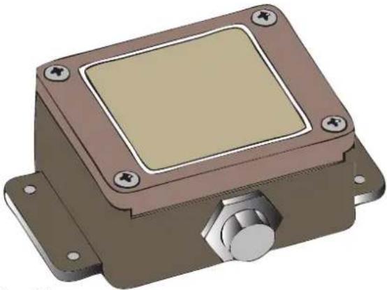
The Ambient Environment Controller (AEC) is a device containing four light sensors. These sensors are used to measure the ambient environment luminance. The control of the AEC is integrated into the software of the Control Software (E.g. RMS-1). The AEC-4000 has been specially developed to be integrated in to a DB-x20 or SLite LED-wall display. The AEC-4000 may be incorporated to a Barco LED-wall, measuring the environmental light conditions through out the day. The modular concept of the AEC-4000 gives rise to configurations with maximum flexibility and controllability. The built-in intelligence of the control software allows the system to detect and configure itself. The mechanical flexibility and small form enables easy installation and quick servicing. AEC-4000 units are only to be used in conjunction with a Barco LED-wall. The Control Software (E.g. RMS-1) has an intelligence control algorithm depending on which the brightness of LED wall is calculated according to the luminance input from AEC-4000
natural_image
3D rendering of a mechanical device with a square top and mounting base (no text or symbols visible)Image2-1
AEC-4000header(R765437K).
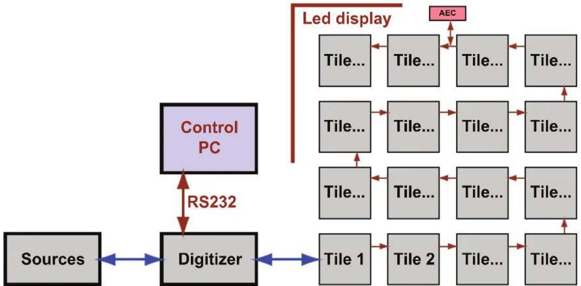
BlockdiagramforsystemwithAEC-4000
The command data stream of the tiles is somewhere interrupted to insert the AEC-4000 in series with the tiles. Where this interruption happens does not matter. The physical location of the AEC-4000 is mostly on top or at the side of the display.
flowchart
graph TD
    A["Sources"] --> B["Digitizer"]
    B --> C["RS232"]
    C --> D["Tile 1"]
    C --> E["Tile 2"]
    C --> F["Tile 3"]
    C --> G["Tile 4"]
    C --> H["Tile 5"]
    C --> I["Tile 6"]
    C --> J["Tile 7"]
    C --> K["Tile 8"]
    C --> L["Tile 9"]
    C --> M["Tile 10"]
    C --> N["Tile 11"]
    C --> O["Tile 12"]
    C --> P["Tile 13"]
    C --> Q["Tile 14"]
    C --> R["Tile 15"]
    C --> S["AEC"]
    T["Control PC"] --> B
    style A fill:#f9f,stroke:#333
    style B fill:#ccf,stroke:#333
    style C fill:#cfc,stroke:#333
    style D fill:#fcc,stroke:#333
    style E fill:#fcc,stroke:#333
    style F fill:#fcc,stroke:#333
    style G fill:#fcc,stroke:#333
    style H fill:#fcc,stroke:#333
    style I fill:#fcc,stroke:#333
    style J fill:#fcc,stroke:#333
    style K fill:#fcc,stroke:#333
    style L fill:#fcc,stroke:#333
    style M fill:#fcc,stroke:#333
    style N fill:#fcc,stroke:#333
    style O fill:#fcc,stroke:#333
    style P fill:#fcc,stroke:#333
    style Q fill:#fcc,stroke:#333
    style R fill:#fcc,stroke:#333
Image2-2
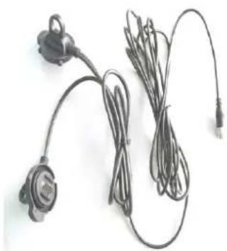
The Y cable used to connect AEC-4000 with other tiles has two paths. One path transmits DVI video signal. This path doesn't enter the AEC-4000 and directly goes to the next tile. The second path transmits the command signal (RS422) and power supply for the AEC-4000. ThesignalinthispathwillentertheAEC-4000andthentransfertothenexttile(onlyRS422).
Orderinfo
| ProductNo.Description | |
| R9861400 | AEC-4000headerunit+MDR“Y”cableforSLitedisplays(5meter). |
| SparepartNo. | Description |
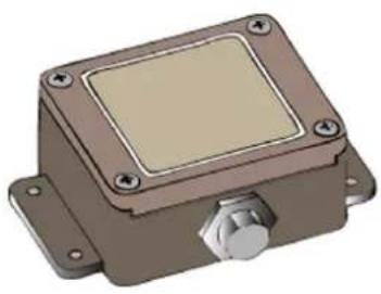
| R765437K | AEC-4000headerunit(suitableforSLiteandDB-x20displays). |
| Z3472040K | MDR“Y”cableforSLitedisplays(5meter) |
Cables&mountingaccessories
natural_image
3D rendering of a rectangular electronic device with mounting flanges and a central square component (no text or symbols visible)Image2-3 AEC-4000headerunit(R765437K).
natural_image
Coiled black cable with earplugs and connectors, no visible text or symbolsImage2-4 MDR"Y"cableforSLitedisplays(Z3472040K).
2.2MountingtheAEC-4000upontheDB-x20display
MountingtheAEC-4000
RefertotheinstallationmanualofDB-x20fortheinstallationdetailsoftheAEC-4000.
2.3MountingtheAEC-4000upontheSLitedisplay
HowtomounttheAEC-4000upontheSLitedisplay?
- FastentheAEC-4000unitupontheSLitedisplay.
- InterruptthedatapathbetweentwoSLitetilesnearbytheAEC-4000.
- ReinstallthedatapathbetweenthetwoSLitetilesusinganMDR"Y"cable.
- ConnecttheMDR"Y" cablewiththeAEC-4000unit.
Caution: Make sure that the thumb screw of the circular plug of the AEC cable is tightly fasten.
2.4 Addressing, Calibrating and Sensing
Addressing, Calibrating and Sensing
Addressing, calibrating and sensing are done with the Control Software (E.g. RMS-1). Instructions for addressing, calibrating and sensing are explained in the user guide of the Control Software (E.g. RMS-1).
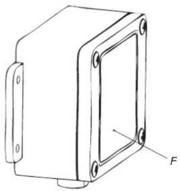
2.5CleaningtheAEC-4000sensors

TheAEC-4000sensorsshouldbecleanedonregularbasisforgoodfunctionalityoftheAEC.
HowtocleantheAEC-4000sensors?
- Remove all dirt from both windows with adamp cloth.
natural_image
Technical line drawing of a rectangular mechanical housing with mounting holes and a labeled force vector (F), no text or symbols present.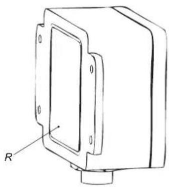
natural_image
Technical line drawing of a mechanical housing or enclosure with mounting holes and a labeled component 'R' (no text or symbols beyond the label)Image2-5 FFrontwindow.R:Rearwindow.
2.6AEC-4000diagnostic
AEC-4000failureandcountermeasures
| Situation | Action |
| 1.Sensorsfailure.2.I2CorEEPROMfailure.NocommunicationwithAECunit.3.Theoutputluminanceofsomesensorsisnotacceptable.4.ThegreenAECcalibrationLEDsinsidetheAECunitcan't beturnedONorOFF. | ReplaceAEC-4000header. |
| ThetileunitsaftertheAEC-4000can'tbedetectedandgiven address. | 1.ReplaceAEC-4000headerandcheckifitworks.Ifnot, proceedwithnextstep.2.Replacethecablesconnectedinthepathofthe AEC-4000unit. |
A.SPECIFICATIONS
Overview
•AEC-4000specifications
•AEC-4000headerdimensions
A.1AEC-4000specifications
SpecificationsoftheAEC-4000
| TypeValue | |
| RuggednessIP65 | |
| Weight368g. | |
| DimensionsHxWxD:85mmx70mmx40mm | |
| Powerconsumption200mWnormaloperation.440mWdiagnosticoperation. | |
| Operatingvoltage6,5–10VDC | |
| OperatingtemperatureMinimum-35°C,maximum50°C. | |
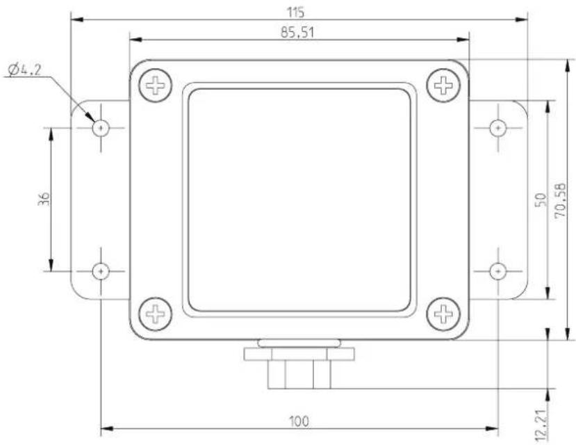
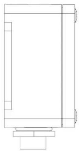
A.2AEC-4000headerdimensions
DimensionsoftheAEC-4000header
natural_image
Pure architectural line drawing of a rectangular room with vertical supports and a central structure (no text or symbols)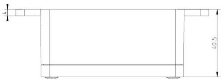
ImageA-1
Dimensionsgiveninmillimeters.
INDEX
A
Addressing12
AEC-40007,10-11,16-17
Dimensions17
Install10-11
Specifications16
C
Calibrating12
Cleaning13
D
Diagnostic14
Dimensions17
AEC-400017
F
Functionality8
|
Importantwarnings6
Instal10-11
AEC-400010-11
Instructions5
S
Safety3
Safetyguidelines4
Sensing12
Specifications15–16
AEC-400016
- Changes
- Copyright©
- FederalCommunicationsCommission(FCCStatement)
- EN55022/CISPR22ClassAITE(InformationTechnologyEquipment)
- GuaranteeandCompensation
- Trademarks
- TABLEOFCONTENTS
- Safety....3
- AEC-4000 7
- Specifications .... 15
- Index....19
- 1.SAFETY
- Aboutthischapter
- Overview
- Safetyguidelines
- Caution
- Productcare
- Important safety instructions
- Instructions:
- Important warnings
- Importantwarnings:
- Riskofelectricshock:
- Maximumandminimumambienttemperature:
- Datacables:
- 2.AEC-4000
- Generalfunctionality
- Introduction
- BlockdiagramforsystemwithAEC-4000
- Cables&mountingaccessories
- 2.2MountingtheAEC-4000upontheDB-x20display
- 2.3MountingtheAEC-4000upontheSLitedisplay
- HowtomounttheAEC-4000upontheSLitedisplay?
- Addressing, Calibrating and Sensing
- Addressing, Calibrating and Sensing
- 2.5CleaningtheAEC-4000sensors
- HowtocleantheAEC-4000sensors?
- 2.6AEC-4000diagnostic
- A.SPECIFICATIONS
- A.1AEC-4000specifications
- A.2AEC-4000headerdimensions
- INDEX
- A
- C
- D
- F
- |
- S
Brand : Barco
Model : R9861400
Category : Projector accessory