
R9853370 - Projector accessory Barco - Free user manual and instructions
Find the device manual for free R9853370 Barco in PDF.


| Product Type | Fiberlink 2 Long Distance (LD) Transmitter Input |
| Model | R9853370 |
| Brand | Barco |
| Compatibility | Fiberlink 2 Base Unit (R9853350), Fiberlink 2 Long Distance Receiver (R9853360) |
| Fiber Type | Single Mode (9/125 µm) |
| Maximum Distance | Up to 5 km (16404 ft) |
| Video Input | DVI-D (single link) |
| Pixel Rate | 64 MHz (dual path support) |
| Frame Delay | None (zero frame delay) |
| Optical Connector | LEMO® (robust push-pull) |
| Communication | RS422 up to 115200 baud |
| Diagnostics | Built-in pattern generator, fiber ping test, temperature and laser power monitoring |
| User Interface | Front jog dial and LCD display per channel, also accessible via TCP/IP web interface |
| Firmware Update | Via TCP/IP or USB (USB-B) on base unit |
| Power Supply (Base Unit) | Auto-ranging: 90-132 VAC / 180-264 VAC, 50-60 Hz |
| Power Consumption (Base Unit) | 50 W max (including up to 3 transmitter units) |
| Operating Temperature (Transmitter) | 0 to 40°C (32 to 104°F) |
| Dimensions (Base Unit) | Standard 19" rack mount, 1U (44 mm) height; depth approx. 300 mm |
| Dimensions (Transmitter Unit) | Plug-in module for base unit; approx. 130 x 40 x 200 mm |
| Weight (Transmitter Unit) | Approx. 0.5 kg |
| Certifications | Class 1 Laser Product (IEC 825), FCC Class A |
| Cleaning Instructions | Use only inert, nonabrasive, noncorrosive materials; no liquids |
| Warranty | Standard Barco warranty; unauthorized modifications void warranty |
Frequently Asked Questions - R9853370 Barco
User questions about R9853370 Barco
0 question about this device. Answer the ones you know or ask your own.
Ask a new question about this device
Download the instructions for your Projector accessory in PDF format for free! Find your manual R9853370 - Barco and take your electronic device back in hand. On this page are published all the documents necessary for the use of your device. R9853370 by Barco.
USER MANUAL R9853370 Barco
natural_image
Illustration of a cable-dissipation device connected to a rectangular electronic device (no text or symbols)Ownersmanual
Barco nv Events
Noordlaan 5, B-8520 Kuurne
Phone: +32 56.36.89.70
Fax: +32 56.36.88.24
E-mail: events@barco.com
Visit us at the web: www.barco.com
Changes
Barco provides this manual 'as is' without warranty of any kind, either expressed or implied, including but not limited to the implied warranties or merchantability and fitness for a particular purpose. Barco may make improvements and/or changes to the product(s) and/or the program(s) described in this publication at any time without notice.
This publication could contain technical inaccuracies or typographical errors. Changes are periodically made to the information in this publication; these changes are incorporated in new editions of this publication.
Copyright ©
All rights reserved. No part of this document may be copied, reproduced or translated. It shall not otherwise be recorded, transmitted or stored in a retrieval system without the prior written consent of Barco.
Federal Communications Commission (FCC Statement)
This equipment has been tested and found to comply with the limits for a class A digital device, pursuant to Part 15 of the FCC rules. These limits are designed to provide reasonable protection against harmful interference when the equipment is operated in a commercial environment. This equipment generates, uses, and can radiate radio frequency energy and, if not installed and used in accordance with the instruction manual, may cause harmful interference to radio communications. Operation of this equipment in a residential area may cause harmful interference, in which case the user will be responsible for correcting any interference.
Guarantee and Compensation
Barco provides a guarantee relating to perfect manufacturing as part of the legally stipulated terms of guarantee. On receipt, the purchaser must immediately inspect all delivered goods for damage incurred during transport, as well as for material and manufacturing faults Barco must be informed immediately in writing of any complaints.
The period of guarantee begins on the date of transfer of risks, in the case of special systems and software on the date of commissioning, at latest 30 days after the transfer of risks. In the event of justified notice of complaint, Barco can repair the fault or provide a replacement at its own discretion within an appropriate period. If this measure proves to be impossible or unsuccessful, the purchaser can demand a reduction in the purchase price or cancellation of the contract. All other claims, in particular those relating to compensation for direct or indirect damage, and also damage attributed to the operation of software as well as to other services provided by Barco, being a component of the system or independent service, will be deemed invalid provide the damage is not proven to be attributed to the absence of properties guaranteed in writing or due to the intent or gross negligence or part of Barco.
If the purchaser or a third party carries out modifications or repairs on goods delivered by Barco, or if the goods are handled incorrectly, in particular if the systems are commissioned operated incorrectly or if, after the transfer of risks, the goods are subject to influences not agreed upon in the contract, all guarantee claims of the purchaser will be rendered invalid. Not included in the guarantee coverage are system failures which are attributed to programs or special electronic circuitry provided by the purchaser, e.g. interfaces. Normal wear as well as normal maintenance are not subject to the guarantee provided by Barco either.
The environmental conditions as well as the servicing and maintenance regulations specified in the this manual must be complied with by the customer.
Trademarks
Brand and product names mentioned in this manual may be trademarks, registered trademarks or copyrights of their respective holders. All brand and product names mentioned in this manual serve as comments or examples and are not to be understood as advertising for the products or their manufactures.
TABLE OF CONTENTS
1. Safety....3
1.1 Important safety instructions....4
1.2 Important warnings....5
2. General....7
2.1 Fiberlink 2 8
2.2 Functionality 9
3. System components....11
3.1 Base unit....12
3.2 Transmitters 13
3.3 Receivers....14
3.4 Optical fiber cables 15
3.5 Power and data cables....17
4. Installation....19
4.1 Installing the Fiberlink 2 base unit 20
4.2 Installing the Fiberlink 2 receiver 22
4.3 Other mounting positions of the Fiberlink 2 receiver....24
4.4 Full installation example 25
5. User interface 27
5.1 Main menu structure 28
5.2 "Diagnostics" menu description....30
5.3 "Pattern GEN" menu description.... 33
5.4 "LED-wall" menu description 35
5.5 "Ethernet conf" menu description 36
5.6 Fiberlink 2 messages (apart from menu messages)....37
6. Maintenance....41
6.1 Diagnoses via TCP/IP 42
6.2 Software update 43
A. Dimensions ....45
A.1 Dimensions of the Fiberlink 2 base unit 46
A.2 Dimensions of the Fiberlink 2 transmitter unit....47
A.3 Dimensions of the Fiberlink 2 receiver 48
B. Specifications ....49
B.1 Fiberlink 2 specifications....50
Order info 51
C.1 Order info 52
Index....53
1. SAFETY
About this chapter
Read this chapter attentively. It contains important safety information concerning product installation and usage. Furthermore, it includes several cautions to prevent damage to the Fiberlink 2. Ensure you understand and follow all the safety guidelines, safety instructions and warnings mentioned in this chapter before installing and using the Fiberlink 2 system. After this chapter additional "warnings" and "cautions" are given depending on the installation or other procedures. Read and follow this "warnings" and "cautions" as well.
Overview
- Important safety instructions
- Important warnings
1.1 Important safety instructions
Instructions:
- Read these instructions.
- Keep these instructions.
- Heed all warnings.
-
Follow all instructions.
-
Clean only with materials or chemicals that are inert, nonabrasive, noncorrosive and non-marking. Consult the manufacturer for further advice should any doubts exist regarding any cleaning procedure.
- Do not block ventilation openings. Install in accordance with the manufacturers instructions.
- Do not install near any heat sources such as radiators, heat registers, stoves, or other apparatus (including amplifiers) that produce heat.
- Do not defeat the safety purpose of the polarized or grounding type plugs/sockets. If the provided sockets/plugs are damaged then replacement of the defective parts must be undertaken immediately.
- Protect the power/data cords from being walked on or pinched particularly at plugs, convenience receptacles, and the point where they exit from the apparatus. Replace damaged power/data cords immediately.
• Only use attachments/accessories specified by the manufacturer. - Disconnect the power to this apparatus during lightning storms or provide suitable additional lightning protection. Unplug this apparatus when unused for long period of time.
• Refer all servicing to qualified service technicians/personnel. Servicing is required when the apparatus has been damaged in any way, such as power-supply cord or plug is damaged, the apparatus does not operate normally, or has been dropped. - Use only with systems or peripherals specified by the manufacturer, or sold with the apparatus. Use ca ution during lifting/moving or transporting to avoid damage by possible tipping.
1.2 Important warnings
Important warnings
- Risk of electric shock:
Do not open. To reduce the risk of electric shock, do not remove cover (or back). No user-serviceable parts inside. Refer servicing to qualified service personnel.
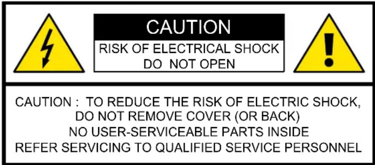
The lightning flash with an arrowhead within a triangle is intended to tell the user that parts inside this product may cause a risk of electrical shock to persons.
The exclamation point within a triangle is intended to tell the user that important operating and/or servicing instructions are included in the technical documentation for this equipment.
• Class 1 laser product:
The Fiberlink 2 does not produce laser radiation hazardous to the user. It is certified as a Class 1 laser product.
CLASS 1 LASER PRODUCT TO IEC 825
• Maximum and minimum ambient temperature:
The maximum ambient temperature for the Fiberlink 2 transmitter is 40^ , the minimum temperature is 0^ . The maximum ambient temperature for the Fiberlink 2 receiver is 50^ , the minimum temperature is -20^ .
- Ventilation:
The Fiberlink 2 transmitter requires that air flows freely in both the front and rear ventilation holes. Blocking these holes will greatly reduce the reliability of the unit an lead to the possibility of overheating. The Fiberlink 2 receiver is equipped with external fans. Ensure that air can flows freely into the fans, otherwise the reliability of the receiver will be reduced and the unit can be overheated.
- Flammable materials:
Keep flammable materials away from the installation (such as curtains). A lot of energy is transferred into heat. The installation should be such that the amount of air flow required for safe operation of the equipment is not compromised. Proper ventilation must be provided.
• This equipment MUST be earthed:
In order to protect against risk of electric shock, the installation should be properly grounded. Defeating the purpose of the grounding type plug will expose you to the risk of electric shock.
- Power system:
It is recommended to use a TN-S power distribution system (a power distribution system with a separate neutral and grounding conductor) in order to avoid large ground currents loops due to voltage differences in the neutral conductor. The total electrical installation should be protected by an appropriate rated disconnect switch, circuit breakers and Ground Fault Current Interrupters. The installation shall be done according to the local electrical installation codes. In Europe special attention should be given to EN 60364, the standard for electrical installation of buildings. In Germany VDE 0100 should be adhered to.
- Disconnect device:
When the appliance inlets of the individual tiles are not accessible, the socket outlets supplying the rack shall be installed near the equipment and be easily accessible, or a readily accessible general disconnect device shall be incorporated in the fixed wiring.
- Mains cords:
The power cords delivered with this system have special properties for safety. They are not user serviceable. If the power cords are damaged, replace only with new ones. Never try to repair a power cord.
- Rack mounting:
When using Fiberlink 2 base unit (TX) in a multi rack assembly or closed assembly, the ambient temperature inside the assembly may not exceed the maximum rated ambient temperature of the Fiberlink 2 transmitter, which is 40^ .
When installed in a rack, the mounting should be such that no hazardous condition is achieved due to uneven mechanical loading.
• Cabinet openings:
Never push objects of any kind into this product through cabinet slots as they may touch dangerous high voltage points or short out parts that could result in a risk of fire or electrical shock.
Never spill liquid of any kind on the product. Should any liquid or solid object fall into the cabinet, unplug the set and have it checked by qualified service personnel before resuming operations.
1. Safety
- Replacement parts:
When replacement parts are required, be sure the service technician has used original Barco replacement parts or authorized replacement parts which have the same characteristics as the Barco original part. Unauthorized substitutions may result in degraded performance and reliability, fire, electric shock or other hazards. Unauthorized substitutions may void warranty.
- Safety check:
Upon completion of any service or repairs to this device, ask the service technician to perform safety checks to determine that the device is in proper operating condition.
2. GENERAL
About this chapter
This chapter contains general information about the Fiberlink 2 concept. Reading this chapter will helps you to identify the different components of the Fiberlink 2 and understand the functionality of it, which will be a benefit during the installation.
Overview
- Fiberlink 2
- Functionality
2.1 Fiberlink 2
Introduction
The Fiberlink 2 is a bidirectional digital fiber optic transmission system between a Barco Digitizer and a Barco LED-wall. It covers real long distances and has a very high bandwidth. This enables the end-user for instance to setup the Digitizer in a remote control room. The Fiberlink 2 transmits not only the video signals but also the communication to the LED-wall. The Fiberlink 2 receiver is sheltered in a compact IP65 housing which makes the receiver usable for indoor and outdoor LED-wall applications. An extensive self-diagnose system has been implemented to display any transmission fault conditions should they arise.
Purpose
The Fiberlink 2 is used to achieve transmission distances of more than 100 meter and up to 5 kilometer between Digitizer and LED-wall.
Note that transmission distances shorter than 100 meter can be achieved by the "Compact link" (See installation manual of the Compact link for more information).
Multi- or single- mode ?
The Fiberlink 2 transmitters and receivers are available in two types. For distances up to 500 me ter the "multi mode" Fiberlink 2 transmitters and receivers are used. The optical fiber cable hereby used is a multi mode duplex 50/125 µm cable and the laser used in transmitter and receiver (bidirectional) is a 850 nm VCSEL laser. Those transmitters and receivers have a grey colored housing with a black colored print.
For distances longer than 500 meter you require a Fiberlink 2 Long Distance (LD) transmitter and receiver with "single mode" optical fiber technology. The optical fiber cable hereby used is a single mode duplex 9/125 µm cable and the laser used in transmitter and receiver (bidirectional) is a 1300 nm FP laser. Those transmitters and receivers are marked with the text "LD" or "Long Distance" and have a black colored housing with a grey colored print.

Multi mode fiber cables can not be used in combination with a single mode (LD) transmitter nor receiver unit, neither can single mode fiber cables be used in combination with a multi mode transmitter nor receiver unit.
2.2 Functionality
System overview
The Fiberlink 2 system is inserted in the data path between the Digitizer and the first tile of the LED-display. One Fiberlink 2 system can handle up to 3 digitizers. Per Digitizer a Fiberlink 2 transmitter unit is inserted into the Fiberlink 2 base unit. The Fiberlink 2 base unit, containing the transmitter unit(s), is installed in the same rack of the Digitizer(s). Each transmitter unit is connected with a fiber optic cable to a Fiberlink 2 receiver unit, which is installed nearby the first tile in the LED-display.
Diagram
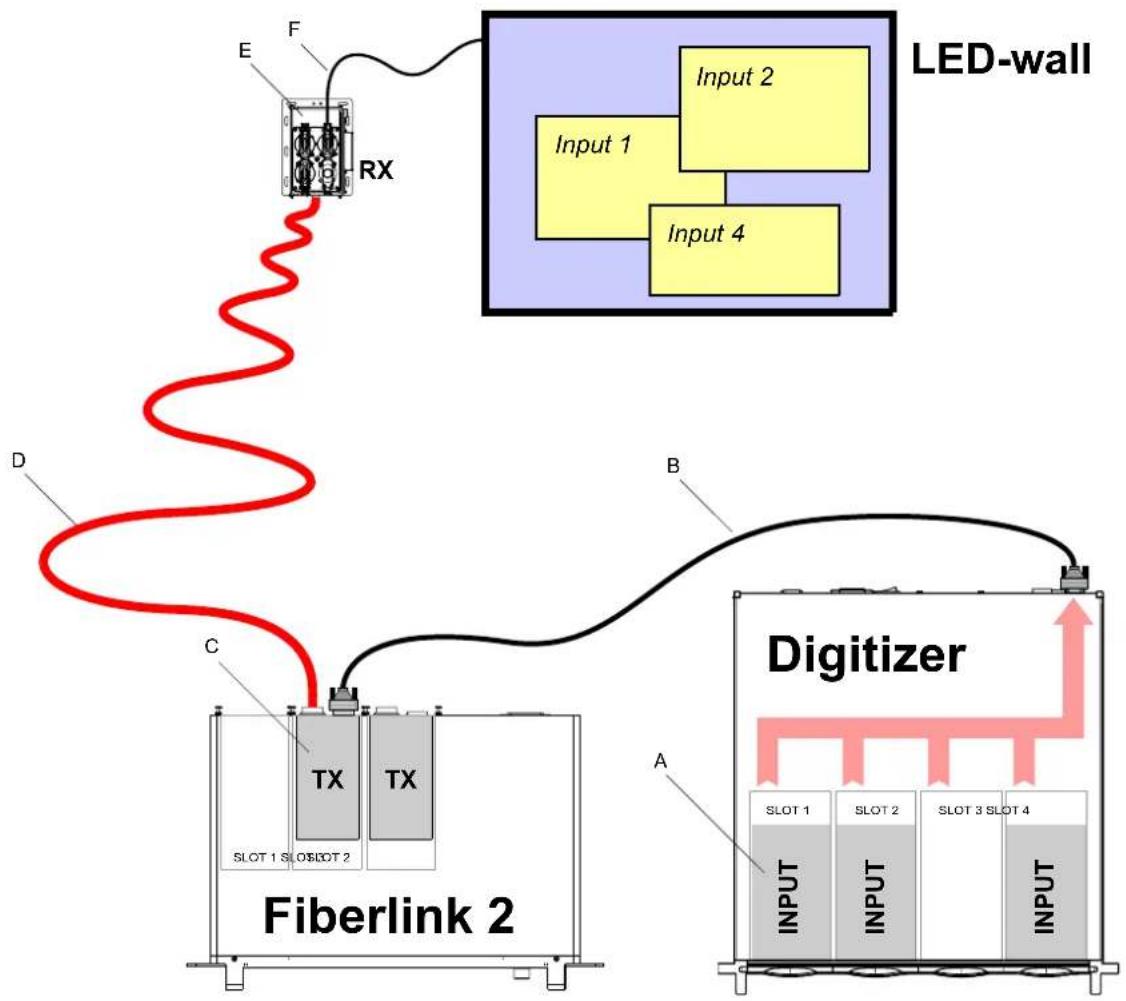
flowchart
graph TD
    A["Fiberlink 2"] --> B["LED-wall"]
    B --> C["Input 1"]
    B --> D["Input 2"]
    B --> E["Input 4"]
    B --> F["Input 1"]
    B --> G["Input 2"]
    B --> H["Input 3"]
    B --> I["Input 4"]
    B --> J["Input 1"]
    B --> K["Input 2"]
    B --> L["Input 3"]
    B --> M["Input 4"]
    B --> N["Input 1"]
    B --> O["Input 2"]
    B --> P["Input 3"]
    B --> Q["Input 4"]
    B --> R["Input 1"]
    B --> S["Input 2"]
    B --> T["Input 3"]
    B --> U["Input 4"]
    B --> V["Input 1"]
    B --> W["Input 2"]
    B --> X["Input 3"]
    B --> Y["Input 4"]
    B --> Z["Input 1"]
Image 2-1
A Digitizer input module.
B DVI cable (R9851211).
C Fiberlink 2 transmitter unit.
D Fiber optic cable.
E Fiberlink 2 receiver unit.
F Data cable to first tile in display.
3. SYSTEM COMPONENTS
About this chapter
This chapter describes the different components of the Fiberlink 2 system.
Overview
- Base unit
- Transmitters
- Receivers
• Optical fiber cables
• Power and data cables
3.1 Base unit
Introduction
The cabinet of the Fiberlink 2 base unit fits in a standard 19" rack (482,6 mm) and has a height of 1U (44 mm). Up to three transmitter units can be inserted into the slots at the rear of the base unit. Each transmitter unit adds a fiber channel to the system. The front of the base unit contains a jog dial and three LCD displays, one per input slot. This jog dial (thumb wheel) allows you to enter the user interface for configuration and diagnostic purposes on each inserted transmitter unit and/or connected receiver unit.
The Fiberlink 2 base unit has an auto ranging power supply between 90 and 132 volt and between 180 and 264 volt (50-60 Hz), which provide power to the local control board and the inserted transmitter units. Furthermore, the base unit is equipped with several small fans that improve the internal airflow to control the heat dissipation. Cool air flows into the base unit cabinet at the front, flows trough the transmitter units (slots) and leaves at the rear.
The rear of the Fiberlink 2 base unit contains an USB and TCP/IP port, which allows software updates and diagnostic via network.
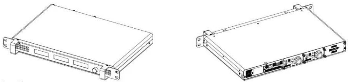
natural_image
Technical line drawings of two electronic device modules (no text or symbols visible)Image 3-1
Connector sockets and input slots of the Fiberlink 2 base unit
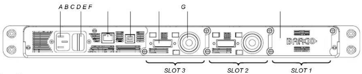
Image 3-2
A Mains power input.
B Power ON/OFF switch.
C TCP/IP port for runtime diagnostics information.
D USB port (field upgrade purposes).
E DVI input port of the transmitter unit, which is inserted in SLOT 3.
F Optical output socket (LEMO connector, connection with receiver unit).
G Dummy cover plate.
3.2 Transmitters
Introduction
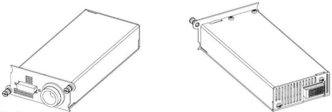
The Fiberlink 2 transmitter unit has a DVI-D input, supports dual path graphics data rate (64 MHz pixel rate) and causes no frame delay. The optical transceiver is equipped with a robust LEMO® connector. Furthermore, the transmitter has an internal pattern generator, a build in fiber test (ping) and supports RS422 communication up to 115200 baud.
The Fiberlink 2 transmitter is available in two types, the short distance module "FIBERLINK" (maximum 500 meter) and the long distance module "FIBERLINK LD" (up to 5 kilometer). The short distance module has a grey colored background with a black colored print. The long distance module has a black colored background and a grey colored print.
natural_image
Technical line drawings of two electronic device modules (no text or symbols visible)Image 3-3

The Fiberlink 2 base unit accepts both types of transmitter units even in a mixed combination (e.g. two short distance modules and one long distance module).

Always use the transmitter unit in combination with the same type of receiver unit.
3.3 Receivers
Introduction
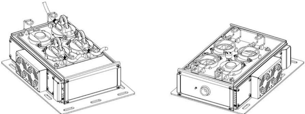
The Fiberlink 2 receiver is sheltered in a compact IP65 housing which makes the receiver usable for indoor and outdoor LED-wall applications. This single fiber channel device has a robust optical LEMO® connector and standard Barco outdoor connector sockets. To energize the receiver unit, which is auto ranging between 190 and 264 volt (50-60 Hz), the unit is electrical connected in the power path of the tiles in the LED display. Furthermore, the receiver has an internal pattern generator, a build in fiber test (ping) and supports RS422 communication up to 115200 baud.
Just like the Fiberlink 2 transmitter the receiver is also available in two types, the short distance module "FIBERLINK" (maximum 500 meter) and the long distance module "FIBERLINK LONG DISTANCE" (up to 5 kilometer). The short distance module has a grey colored background with a black colored print. The long distance module has a black colored background and a grey colored print.
The receiver unit can be upgraded in the field over fiber while operating (if connected to a transmitter unit) or via USB cable by removing the dummy input.
natural_image
Technical line drawings of two electronic device modules with fans and internal components (no text or symbols)Image 3-4
Mounting plate and connector sockets of a Fiberlink 2 receiver
To facilitate the physical installation of the Fiberlink 2 receiver, the receiver is equipped with a mounting plate containing several mounting holes. With hammer bolts, included in the system, the receiver can easily be mounted against the rear of a Barco LED-wall supporting structure.
Barco uses special designed sockets for outdoor power and data connections from tile to tile and to other peripherals like the Fiber-link 2 receiver. These rugged sockets are watertight (IP65) when used with the appropriate plugs and sealing rings. Each socket is equipped with a plug holder clamp which, when locked, ensure that the plug is completely pressed into the socket.
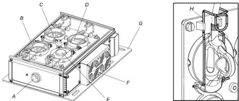
Image 3-5
A Optical input (LEMO connector, connection with Fiberlink 2 transmitter unit).
B Power input socket.
C Power output socket.
D Data output socket (connection with first tile in the LED-wall).
E Socket cover for USB port (field upgrade purposes).
F External fans.
G Mounting plate
H Plug holder clamp.
3.4 Optical fiber cables
Introduction
The optical fiber cable, used between the Fiberlink 2 transmitter and receiver, can be installed by a third party, specialized in optical fiber installations. When realizing the fiber channel yourself take into account the fragility of the fiber cable. Note that the placement of optical fiber cables are subject to special installation instructions enforced by the fiber cable manufacturer. Some general instructions are:
- Never bend the optical fiber cable too sharp.
• Always use a bend radius of at least 10 centimeter. - Place the fiber cable into a cable guard.
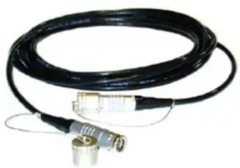
Barco offers two types of fiber optic cables. The multi mode (MM) fiber optic cable and the single mode (SM) fiber optic cable. Both types are equipped with robust optical LEMO® plugs and are available in different lengths, see chapter "Order info".
natural_image
Coiled black cable with metallic connectors and connectors (no text or symbols visible)Image 3-6
Optical fiber cable with LEMO® plugs.

Always use a single mode fiber optic cable (SM) with a long distance (LD) transmitter and receiver unit and a multi mode fiber optic cable (MM) with a short distance transmitter and receiver unit.

To protect the fiber entrance place the protective cap upon the LEMO® plug in case the plug is not inserted into a peripheral. Align the red dot on the cap with the red dot on the plug and then push the cap over the plug until an audible click ensure that the plug is well inserted.
Which optical fiber cable to use?
The Fiberlink 2 requires optical fiber cables with a minimum bandwidth depending on the length of the fiber channel. Consult the table below to choose the correct fiber cable for your Fiberlink 2 system.
| Length fiber channel | Fiber type | Minimum bandwidth of fiber |
| 0 - 3 0 0 meter | Multi mode fiber | 500 MHz.km |
| 300 - 500 meter | Multi mode fiber | 2000 MHz.km |
| 500 - 5000 meter | Single mode fiber | — |
Pre-installed optical fiber network
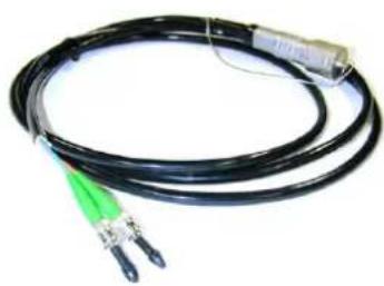
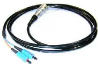
The Fiberlink 2 can make use of a pre-installed (permanent) network of optical fiber cables. Those pre-installed fibers starts and ends in patch panels provided with industrial standard optical connector sockets like ST or SC, which can be connected with a (short) optical fiber cable and adapted plugs to the desired peripherals. Note that, next to the length, each connection in the path of the fiber channel causes a little decrease of the signal power. The two illustrations below show adapted optical fiber cables, to connect the Fiberlink 2 transmitter with the patch panel of the optical fiber network.
natural_image
Coiled black cable with two connectors and a connector housing (no text or symbols visible)Image 3-7 Short optical fiber cable with LEMO® plug and SC connectors.
natural_image
Coiled black fiber optic cable with blue and orange connectors (no text or symbols visible)Image 3-8 Short optical fiber cable with LEMO® plug and ST connectors.
3.5 Power and data cables
General
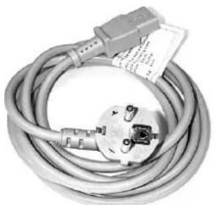
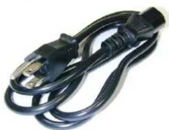
Next to the fiber optic cables there are also the power and data cables required to realize the connections in the first place between Digitizer and Fiberlink 2 transmitter and in the second place between Fiberlink 2 receiver and LED-wall. Note that the cables used between receiver and LED-wall are different for an outdoor LED-wall than for an indoor LED-wall.
natural_image
Coiled electrical plug with attached terminal connector (no visible text or symbols)Image 3-9 CEE power cord for Fiberlink 2 base unit (R326103).
natural_image
Coiled black electrical power plug with metal terminal (no text or symbols visible)Image 3-10 CEI power cord for Fiberlink 2 base unit (R3261115).
natural_image
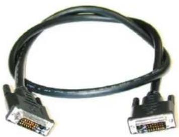
Coiled black DVI cable with two connectors (no text or symbols visible)Image 3-11 DVI cable for connection between Digitizer and Fiberlink 2 transmitter (R9851211).
natural_image
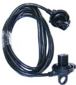
Black cable with connector and mounting bracket, no visible text or symbolsImage 3-12 Waterproof power cable (5 meter) to connect Fiberlink 2 receiver with indoor or outdoor LED-wall (R9850250).

natural_image
Pair of black cable connectors with connector pins, no visible text or symbolsImage 3-13 Waterproof MDR cable (5 meter) to connect Fiberlink 2 receiver with outdoor LED-wall (R9850220).
natural_image
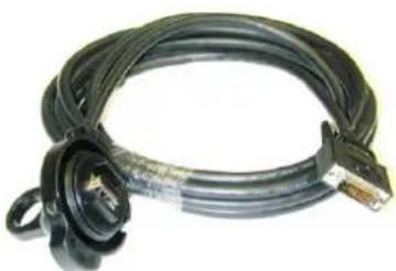
Coiled black cable with a connector, no visible text or symbolsImage 3-14 MDR-DVI cable (5 meter) to connect Fiberlink 2 receiver with Indoor LED-wall (R9851217).
4. INSTALLATION
General
This chapter describes the physical installation of the Fiberlink 2 transmitter unit(s) and the Fiberlink 2 receiver(s).
Overview
• Installing the Fiberlink 2 base unit
• Installing the Fiberlink 2 receiver
- Other mounting positions of the Fiberlink 2 receiver
• Full installation example
4.1 Installing the Fiberlink 2 base unit
What has to be done?
Physical installation and cabling of the Fiberlink 2 base unit and transmitter unit(s) in a 19 inch mounting rack. One transmitter unit is required per stacked Digitizer. It's recommended to build the Fiberlink 2 base unit in the same 19 inch rack as the Digitizer(s).
Necessary tools
- Flat blade screwdriver.
- Nut driver.
Necessary parts
- Fiberlink 2 base unit.
• Fiberlink 2 transmitter unit(s).
• 19 inch mounting rack.
• Fixation parts for rack mounting.
• DVI cable per transmitter unit.
• Fiber optic cable per transmitter unit. - CEE or IEC power cord (depends on local power system).
How to install the Fiberlink 2 base unit and transmitter unit(s)?
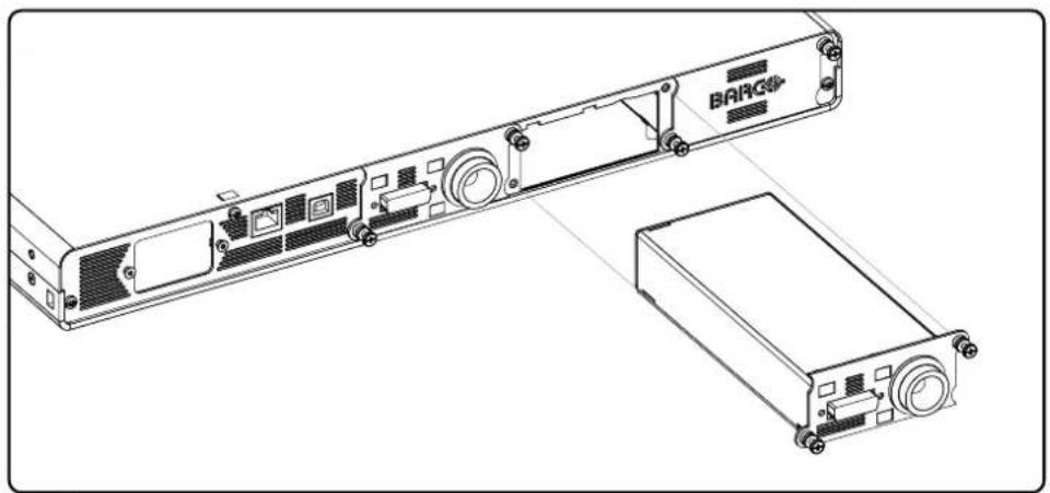
- Remove the dummy cover plate(s) of the input slot(s) and insert the transmitter unit(s) as illustrated. Use a flat blade screwdriver to release and to fasten the two captive screws of the cover plate(s) and transmitter unit(s). Note: Ensure that you insert the appropriate transmitter unit according to the communication distance to bridge. Distances longer than 500 meter require a long distance (LD) transmitter unit and a single mode (SM) fiber optic cable.
natural_image
Technical line drawing of a rack-mounted device with labeled BARGS ports and a separate base unit (no text or symbols beyond branding)Image 4-1
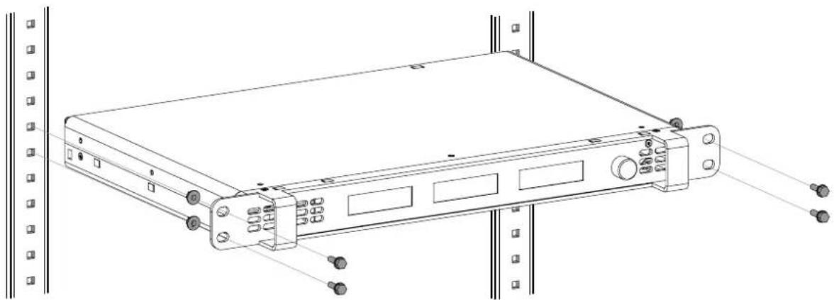
- Fasten the Fiberlink 2 base unit into a 19 inch rack as illustrated. Use two screws at both sides of the base unit front plate.
natural_image
Technical line drawing of a rack-mounted server unit with mounting holes and drive slots (no text or symbols)Image 4-2
- Connect the LED-WALL OUTPUT (A) of the Digitizer(s) with a DVI cable (B) to the DVI input (C) of the transmitter unit(s). Note: Fasten the thumbscrews of the DVI cable.
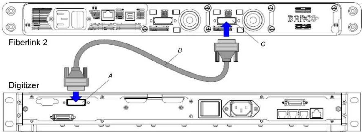
Image 4-3
-
Remove the protective cap of the LEMO socket (fiber entrance).
-
Align the red dot on the plug of the fiber cable with the red dot on the socket and then push the p lug into the socket until an audible click ensures the plug is well inserted.
Caution: Handle the fiber optic cable with care. Do not crack the fiber optic cable by bending it too sharp. At least 200 millimeters of free area is required behind the Fiberlink 2 transmitter to ensure a smooth curve of the fiber optic cable.
Note: In case of using multiple transmitter units, ensure that you connect the right display with the right transmitter unit, otherwise content would be mixed up or not displayed at all.
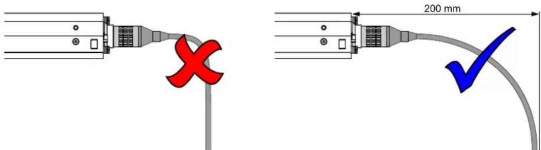
Image 4-4
-
Plug the power cord into the mains input at the rear of the Fiberlink 2 base unit. Note: The Fiberlink 2 system is provide with two types of power cords. One CEE/C13 and one IEC/C13 power cord. Depending on the local power net use the appropriate power cord.
-
Energize the Fiberlink 2 base unit with inserted transmitter units by switching on the main switch at the rear of the Fiberlink 2 base unit.

The transmitter units can not be hot swapped. After the transmitter units are inserted, reboot the Fiberlink 2 base unit by switching the base unit OFF and ON.
4.2 Installing the Fiberlink 2 receiver
What has to be done?
Physical attachment and cabling of the Fiberlink 2 receiver nearby the first tile in the LED-wall. The exact location of the Fiberlink 2 receiver will vary depending on the LED-wall application. The procedure below describes one of the physical installation possibilities of the Fiberlink 2 receiver.

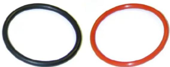
WARNING: Be sure that the connector sockets are provided with sealing rings before plugging in the power and data cables. Use the correct sealing ring for the corresponding socket. Black colored ring (B361243, left image) for power, red (B361595, right image) for data. Replace damaged sealing rings immediately.
natural_image
Two circular ring shapes, one black and one red, on a white background (no text or symbols)
WARNING: Ensure that all plug holder clamps of the outdoor tiles and the Fiberlink 2 receiver are locked firmly after installation.

CAUTION: Always install the Fiberlink 2 receiver with the optical input (LEMO connector) downwards.
Necessary tools
10 or 13 millimeter nut driver (depends on LED-wall structure).
Necessary parts
• Fiberlink 2 receiver unit.
- Four M5 hammer bolts with nuts (B362166).
• Four spacers (V3673807).
- Four M8 hammer bolts (B360624) with nuts (B3606235).
• Power cable for indoor and outdoor use (R9850250).
- Indoor data cable (R9851217).
• Outdoor data cable (R9850220).
How to install the Fiberlink 2 receiver?
- Fasten the receiver unit against the rear of the LED-wall structure with the optical input downwards as illustrated. Depending on the profiles of the structure, use the four larger or smaller hammer bolts with matching nuts and spacers. Caution: Ensure that the fans are not covered by the profiles of the LED-wall structure or by other equipment.
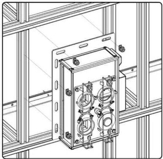
natural_image
Technical line drawing of an electrical enclosure with four circular components mounted on a wall, enclosed within a metal frame (no text or symbols)Image 4-5
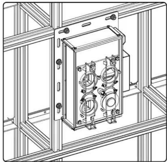
natural_image
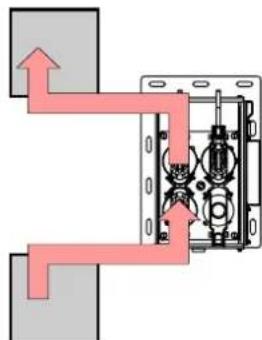
Technical line drawing of an electrical enclosure mounted on a metal frame structure (no text or symbols)- Connect the Fiberlink 2 receiver with one of the power circuits of the Barco LED-wall. Do this by interrupting a power circuit of the tiles somewhere nearby the receiver, and connecting the power ports of the receiver with the power ports of the two tiles at the interruption. So the power flows from tile to receiver and then from receiver to the next tile.
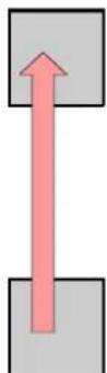
Image 4-6

natural_image
Pure mechanical diagram showing pipe connections and internal components without any text or symbolsTip: A second possibility is to connect the power input connector of the receiver with the unused power output connector of the last tile in a power circuit nearby the receiver. In this case the power output socket of the receiver is not used and needs to be sealed with a dummy power plug in case of an outdoor application. Note that the power cable for the receiver, included in the Fiberlink 2 package, has a length of 5 meter. So, in most cases an unused power output connector can be found nearby the receiver.
Caution: Ensure that the plug holder clamps are locked firmly.
- Connect the data output socket of the Fiberlink 2 receiver with the data input socket of the first tile in the LED-wall. Use the appropriate data cable for the indoor or outdoor LED-wall. Ensure that the plug holder clamps are locked firmly.
Note: Two types of data cables are included with the Fiberlink 2 receiver. One to realize the data connection between the receiver and an indoor LED-wall and one to realize the connection with an outdoor LED-wall. The data cable for outdoor use has two waterproof plugs, the indoor version only one.
-
Remove the protective cap of the LEMO socket (fiber entrance).
-
Align the red dot on the plug of the fiber cable with the red dot on the socket and then push the plug into the socket until an audible click ensures the plug is well inserted.
Caution: Handle the fiber optic cable with care. Do not crack the fiber optic cable by bending it to short. At least 200 millimeters of free area is required below the Fiberlink 2 receiver to ensure a smooth curve of the fiber optic cable.

CAUTION: In case you use the power output socket of the receiver be aware that the maximum output current not exceeds 14 amperes.
4.3 Other mounting positions of the Fiberlink 2 receiver
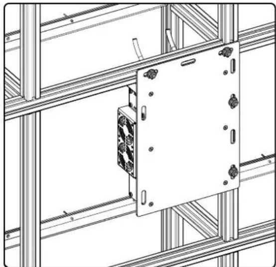
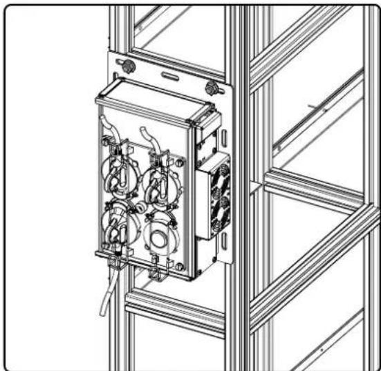
Example of other mounting positions of the Fiberlink 2 receiver
Some LED-wall installations do not let sufficient space behind the support structure to install the Fiberlink 2 receiver as described in the procedure before. The illustrations below show some other mounting positions of the receiver as a solution for this lack of space. Ensure the fans are never blocked.
natural_image
Technical line drawing of a metal enclosure mounted on a structural frame (no text or symbols)Image 4-7
natural_image
Technical line drawing of an electrical cabinet with four motors and wiring, mounted on a metal frame (no text or symbols)4.4 Full installation example
Full installation example
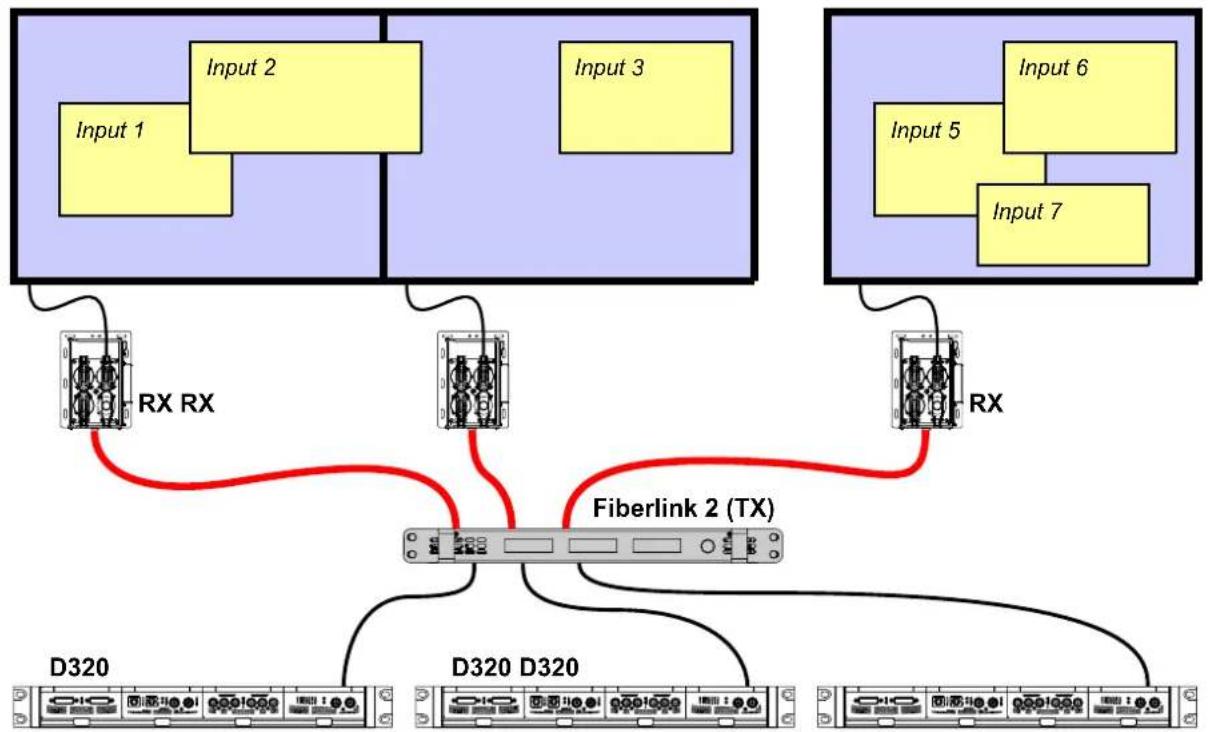
The illustration below shows the data path of a Fiberlink 2 system with three transmitter units and three receiver units.
flowchart
graph TD
    subgraph_D320["D320"]
        A1["Input 1"] --> B1["Input 2"]
        A2["Input 2"] --> B2["Input 3"]
    end
    subgraph_D320D320["D320"]
        B3["Input 5"] --> C3["Input 6"]
        B4["Input 7"] --> C4["Input 6"]
        B5["Input 7"] --> C5["Input 6"]
    end
    B1 -->|RX RX| B3
    B2 -->|RX RX| B4
    B3 -->|RX RX| B5
    B4 -->|RX RX| B5
    B5 -->|Fiberlink 2 (TX)| B6["Fiberlink 2 (TX)"]
    style D320 fill:#f9f,stroke:#333
    style D320D320 fill:#ccf,stroke:#333
Image 4-8
5. USER INTERFACE
General
The Fiberlink 2 is a plug and play device. Nevertheless, a user interface is provided mainly for diagnostic purposes. The user interface exists in one jog dial and three LCD displays, one per fiber channel. The user interface allows you to retrieve the current software versions, information about the lasers or the timings of the DVI input. Furthermore, with the user interface you can activate and adjust the pattern generator either on the transmitter or the receiver. Ethernet addresses can also be retrieved and configured via the user interface of the Fiberlink 2.

Most of the functionality of the user interface can also be achieved with the control software used to configure the complete LED-wall system (e.g. Director toolset).

Image 5-1
A LCD display dedicated to fiber channel 1.
B LCD display dedicated to fiber channel 2.
C LCD display dedicated to fiber channel 3.
D Jog dial.
Using the jog dial
The jog dial (thumb wheel) has four functions:
• Browsing : Turn the jog dial to browse through the menus.
- Selecting: Push the jog dial shortly to enter one of the menus.
- Adjusting : Turn the jog dial either clockwise (+) or counterclockwise (-) to adjust the value of one of the previous selected parameters.
- Escaping: Push the jog dial about 1 second to go back to the parent menu. Note that selecting “<<” will also result in going back to the parent menu. Push the jog dial more than 2 seconds to close the user interface.
Activating the user interface
Push the jog dial shortly to activate the user interface. The LCD display of fiber channel 1 (most left) will display the text:
“ > ENTER MENU < “.
Turn the jog dial to select one of the other fiber channels or push the jog dial to enter the main menu for that fiber channel. Note that after an inactive period of 30 seconds the user interface is automatically closed and the LCD display shows repeatedly some parameter values (versions, temperature, power, etc.) of the fiber channel. In case of an empty input slot, the displayed message is:
"No input Detected".
Overview
• Main menu structure
• "Diagnostics" menu description
• "Pattern GEN" menu description
• "LED-wall" menu description
• "Ethernet conf" menu description
• Fiberlink 2 messages (apart from menu messages)
5.1 Main menu structure
Overview "Main menu"
• Diagnostics
- Versions
- TXSoftware
- TXFirmware
- TXInput
- RXSoftware
- RXFirmware
- Laser
- TXStatus
-
RXStatus
Power -
TX->powerout
- TX->powerin
- RX->powerout
- RX->powerin
- TXinfo
- Vendorname
- Wavelength
- Nom.bitrate
- Length9/125
- Length9/125
- Length50/125
- Length62.5/125
- RXinfo
- Vendorname
- Wavelength
- Nom.bitrate
- Length9/125
- Length9/125
- Length50/125
- Length62.5/125
- DVItimings
- PPL
○ LPF - CLK
- PS
○ AP - LS
○ AL - vsync
- PPLLastline
- Ethernet
- IPAddress
- GWAddress
- NMAddress
- MACAddress
- Temperature
- TXFPGAtemp
- TXLasertemp
- RXFPGAtemp
- RXLasertemp
- Pattern GEN
- TX
- EnablePatt
- PattTimings
o PPL - HS-Width
○ LPF - vs-Width
PS
o AP - LS
o AL -
DUALPath
SAVE -
PattSettings
- Type
- Color
- Colorporch
- Motion
- RX
- EnablePatt
- PattTimings
o PPL - HS-Width
o LPF - VS-Width
PS
○ AP - LS
o AL - DUALPath
- SAVE
- PattSettings
- Type
- Color
- Colorporch
- Motion
- LED-wall
- Ethernetconf
- Enableeth
- DHCP
- StaticIP
- StaticNM
- StaticGW
5.2 "Diagnostics" menu description
Diagnostics > Versions > TX Software
Shows the version of the software used in the Fiberlink 2 base unit. Note that the TX software can be updated via the TCP/IP or USB port of the base unit or via the control software like the Director toolset if connected to a Digitizer. The latest software version is available in the secured Partner Zone section of the Barco web site.
Diagnostics > Versions > TX Firmware
Shows the version of the firmware used in the Fiberlink 2 base unit. Note that the TX firmware can be updated via the TCP/IP or USB port of the base unit or via the control software like the Director toolset if connected to a Digitizer. The latest firmware version is available in the secured Partner Zone section of the Barco web site.
Diagnostics > Versions > TX Input
Shows the version of the firmware used in the Fiberlink 2 transmitter unit. Note that the TX input firmware can be updated via the TCP/IP of the base unit or via the control software like the Director toolset if connected to a Digitizer. The latest firmware version is available in the secured Partner Zone section of the Barco web site.
Diagnostics > Versions > RX Software
Shows the version of the software used in the Fiberlink 2 receiver. Note that the RX software can be updated via the TCP/IP port of the base unit or via the USB port of the receiver or via the control software like the Director toolset if connected to a Digitizer. The latest software version is available in the secured Partner Zone section of the Barco web site.
Diagnostics > Versions > RX Firmware
Shows the version of the firmware used in the Fiberlink 2 receiver. Note that the RX firmware can be updated via the TCP/IP port of the base unit or via the USB port of the receiver or via the control software like the Director toolset if connected to a Digitizer. The latest firmware version is available in the secured Partner Zone section of the Barco web site.
Diagnostics > Laser > TX Status
Shows the status of the laser in the transmitter unit:
- LINKUP: normal operation.
- Laser failed to lock: transmitter and receiver failed to go in sync with each other. Check if the plug of optical fiber cable is well inserted and ensure that the optical fiber cable is not damaged.
- NoLaser: no laser module was detected.
- FATAL ERROR PLEASE REBOOT: catastrophic error occurred from which the device could not recover. Switch the Fiberlink 2 base unit OFF and ON.
Diagnostics > Laser > RX Status
Shows the status of the laser in the receiver unit:
- LINKUP: normal operation.
- Laser failed to lock: transmitter and receiver failed to go in sync with each other. Check if the plug of optical fiber cable is well inserted and ensure the optical fiber cable is not damaged.
• No Laser: no laser module was detected. Contact a service technician to solve the problem. - FATAL ERROR PLEASE REBOOT: catastrophic error occurred from which the device could not recover. Restart the Fiberlink 2 receiver (power off and on).
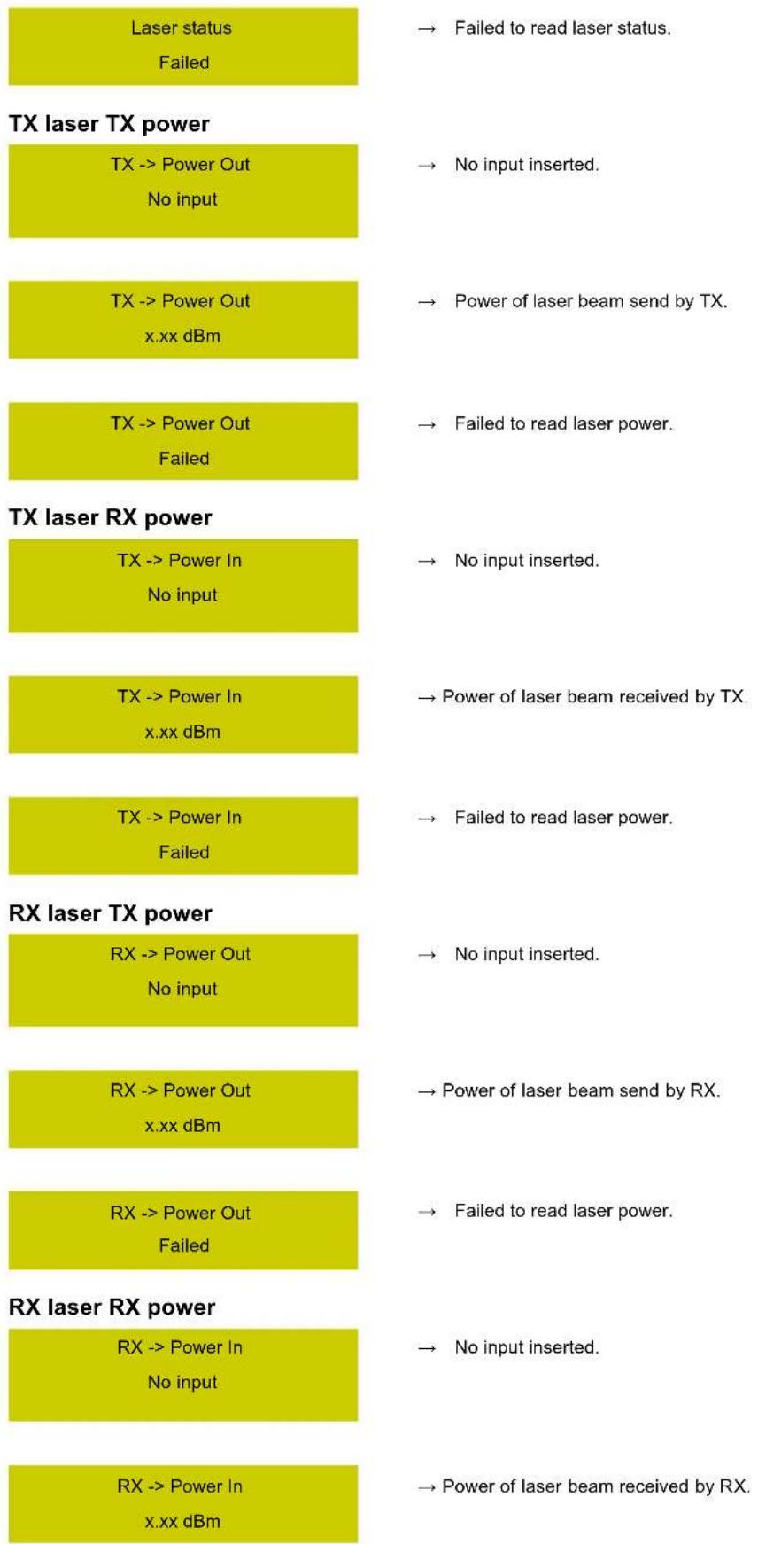
Diagnostics > Laser > Power > TX → power out
Shows the power value of the outgoing laser beam at the transmitter unit. Values around -5 dBm (e.g. "-6.11 dBm") are very good but values around -20 dBm are weak and are indicative of a malfunction laser of the transmitter unit. (e.g. "-20.66 dBm").
Diagnostics > Laser > Power > TX → power in
Shows the power value of the incoming laser beam at the transmitter unit. Values around -5 dBm (e.g. "-8.15 dBm") are very good but values around -20 dBm are weak and are indicative of a malfunction laser of the receiver or a damaged optical fiber cable (e.g. "-21.52 dBm"). Note that the longer the optical fiber cable the weaker the optical signal will be.
Diagnostics > Laser > Power > RX → power out
Shows the power value of the outgoing laser beam at the receiver unit. Values around -5 dBm (e.g. “-6.02 dBm”) are very good but values around -20 dBm are weak and can possible indicate a malfunction of the laser of the receiver unit. (e.g. “-21.52 dBm”). In case the message “Failed” appears means that the receiver unit does not respond to the request of the transmitter unit. Probably the optical fiber link is interrupted or the receiver is powerless.
Diagnostics > Laser > Power > RX → power in
Shows the power value of the incoming laser beam at the receiver unit. Values around -5 dBm (e.g. "-6.94 dBm") are very good but values around -20 dBm are weak and can possible indicate a malfunction of the laser of the transmitter unit or a damaged
optical fiber cable (e.g. "-20.55 dBm"). Note that the longer the optical fiber cable the weaker the optical signal will be. In case the message "Failed" appears means that the receiver unit does not respond to the request of the transmitter unit. Probably the optical fiber link is interrupted or the receiver is powerless.
Diagnostics > Laser > Power > TX info > Vendor name
Shows the vendor name of the laser used in the transmitter unit.
Diagnostics > Laser > Power > TX info > Wavelength
Shows the wavelength of the laser used in the transmitter unit.
Diagnostics > Laser > Power > TX info > Nom. bit rate
Shows the nominal bit rate (units of 100 MBits/sec) of the transmitter unit.
Diagnostics > Laser > Power > TX info > Length 9/125
Shows the maximum cable length, in meters or kilometers, that the laser in the transmitter unit supports in case of using a 9/125 m single mode optical fiber cable.
Diagnostics > Laser > Power > TX info > Length 50/125
Shows the maximum cable length, in meters, that the laser in the transmitter unit supports in case of using a 50/125 m multi mode optical fiber cable.
Diagnostics > Laser > Power > TX info > Length 62.5/125
Shows the maximum cable length, in meters, that the laser in the transmitter unit supports in case of using a 62.5/125 m multi mode optical fiber cable.
Diagnostics > Laser > Power > RX info > Vendor name
Shows the vendor name of the laser used in the receiver unit.
Diagnostics > Laser > Power > RX info > Wavelength
Shows the wavelength of the laser used in the receiver unit.
Diagnostics > Laser > Power > RX info > Nom. bit rate
Shows the nominal bit rate (units of 100 MBits/sec) of the receiver unit.
Diagnostics > Laser > Power > RX info > Length 9/125
Shows the maximum cable length, in meters or kilometers, that the laser in the receiver unit supports in case of using a 9/125 m single mode optical fiber cable.
Diagnostics > Laser > Power > RX info > Length 50/125
Shows the maximum cable length, in meters, that the laser in the receiver unit supports in case of using a 50/125 m multi mode optical fiber cable.
Diagnostics > Laser > Power > RX info > Length 62.5/125
Shows the maximum cable length, in meters, that the laser in the receiver unit supports in case of using a 62.5/125 m multi mode optical fiber cable.
Diagnostics > DVI timings > PPL
Shows the "Pixels Per Line" value of the incoming DVI signal on the transmitter unit.
Diagnostics > DVI timings > LPF
Shows the "Lines Per Field" value of the incoming DVI signal on the transmitter unit.
Diagnostics > DVI timings > CLK
Shows the "Clock frequency" in MHz of the incoming DVI signal on the transmitter unit.
Diagnostics > DVI timings > PS
Shows the start position of the first active pixel (Pixel Start) of the incoming DVI signal on the transmitter unit.
Diagnostics > DVI timings > AP
Shows the amount of "Active Pixels" of the incoming DVI signal on the transmitter unit.
Diagnostics > DVI timings > LS
Shows the start position of the first active line (Line Start) of the incoming DVI signal on the transmitter unit.
Diagnostics > DVI timings > AL
Shows the amount of "Active Lines" of the incoming DVI signal on the transmitter unit.
Diagnostics > DVI timings > Vsync
Shows the vertical sync (frame rate) in Hz of the incoming DVI signal on the transmitter unit.
Diagnostics > DVI timings > PPL Last Line
Shows the amount of pixels in the last line of the incoming DVI signal on the transmitter unit.
Diagnostics > Ethernet > IP Address
Shows the Internet Protocol Address.
Diagnostics > Ethernet > GW Address
Shows the Gate Way Address.
Diagnostics > Ethernet > NM Address
Shows the Net Mask Address.
Diagnostics > Ethernet > MAC Address
Shows the MAC Address.
Diagnostics > Temperature > TX FPGA temp
Shows the temperature of the FPGA in the transmitter unit.
Diagnostics > Temperature > TX Laser temp
Shows the temperature of the laser in the transmitter unit.
Diagnostics > Temperature > RX FPGA temp
Shows the temperature of the FPGA in the receiver.
Diagnostics > Temperature > RX Laser temp
Shows the temperature of the laser in the receiver.
5.3 "Pattern GEN" menu description

The pattern generator menus for the transmitter unit (TX) are the same for the receiver unit (RX).
Pattern GEN > TX (RX) > Enable Patt
ENABLE or DISABLE the pattern generator. Note that the internal pattern generator of the tile takes priority to the pattern generator of the Fiberlink 2 receiver and on its turn, the pattern generator of the receiver takes priority to the pattern generator of the Fiberlink 2 transmitter unit.
Pattern GEN > TX (RX) > Patt Timings > PPL
Adjust the pixels per line of the pattern generator. Factory default: 840 pixels.
Pattern GEN > TX (RX) > Patt Timings > HS-Width
Adjust the width of the horizontal sync in pixels of the pattern generator. Factory default: 10 pixels.
Pattern GEN > TX (RX) > Patt Timings > LPF
Adjust the pixels per field of the pattern. Factory default : 635 pixels.
Pattern GEN > TX (RX) > Patt Timings > VS-Width
Adjust the width of the vertical sync in pixels of the pattern. Factory default : 10 pixels.
Pattern GEN > TX (RX) > Patt Timings > PS
Adjust the start position of the first active pixel (Pixel Start) of the pattern. Factory default : 36.
Pattern GEN > TX (RX) > Patt Timings > AP
Adjust the amount of active pixel (pixels displayed) of the pattern. Factory default : 800.
Pattern GEN > TX (RX) > Patt Timings > LS
Adjust the start position of the first active line (Line Start) of the pattern. Factory default : 12.
Pattern GEN > TX (RX) > Patt Timings > AL
Adjust the amount of active lines (lines displayed) of the pattern. Factory default: 600.
Pattern GEN > TX (RX) > Patt Timings > DUAL Path
Choice between SINGLE and DUAL path. Dual path means that the pixel rate of the generated pattern is doubled.
Pattern GEN > TX (RX) > Patt Timings > SAVE
Choice between OK and CANCEL. Select OK if you want to save the previous changes to the values of the pattern timings.
Pattern GEN > TX (RX) > Patt Settings > Type > Edit Type ?
Select the pattern type. Choices are:
- CrossHatch
- ByteLevel
• Bocks - HMultiBurst
- VMultiBurst
- HSawTooth
- VSawTooth
Pattern GEN > TX (RX) > Patt Settings > Type > Edit Width ?
Set the width of the pattern lines between 1 and 4 pixels (values between 0 and 3).
Pattern GEN > TX (RX) > Patt Settings > Type > Edit Outline ?
ENABLEor DISABLEthe outline of the pattern.
Pattern GEN > TX (RX) > Patt Settings > Type > Edit Bytelevel ?
Set the byte level of the pattern between 0 (dark) and 255 (bright).
Pattern GEN > TX (RX) > Patt Settings > Type > SAVE ?
Save the changes done to the settings of the pattern type.
Pattern GEN > TX (RX) > Patt Settings > Color
Change the color of the pattern. Choices are:
- RGB
- RG_
- R_B
- _RB
- R_
- _G_
- _B
-
Pattern GEN > TX (RX) > Patt Settings > Color porch
Change the color of the pattern porch. Choices are:
- RGB
- RG_
- R_B
- _RB
- R_
- _G_
- _B
- _
Pattern GEN > TX (RX) > Patt Settings > Motion > Edit V Motion ?
ENABLEOR DISABLEthe vertical motion of the pattern.
Pattern GEN > TX (RX) > Patt Settings > Motion > Edit H Motion ?
ENABLEOR DISABLEthe vertical motion of the pattern.
Pattern GEN > TX (RX) > Patt Settings > Motion > Edit V Up ?
Select the direction, UP or DOWN, of the vertical motion of the pattern.
Pattern GEN > TX (RX) > Patt Settings > Motion > Edit H Left ?
Select the direction, LEFT or RIGHT, of the horizontal motion of the pattern.
Pattern GEN > TX (RX) > Patt Settings > Motion > Edit Color roll ?
ENABLEor DISABLEthe color roll of the pattern.
Pattern GEN > TX (RX) > Patt Settings > Motion > SAVE ?
Save the changes done to the motion settings of the pattern.
5.4 "LED-wall" menu description
LED-wall > ON / OFF
Choice to switch the LED-wall ON or OFF.
5.5 "Ethernet conf" menu description
Ethernet conf > Enable eth
ENABLE or DISABLE the Ethernet communication. After a change, reboot the Fiberlink 2 base unit by switching the base unit OFF and ON to validate the setting.
Ethernet conf > DHCP
Choice between DHCP or STATIC network address. After a change, reboot the Fiberlink 2 base unit by switching the base unit OFF and ON to validate the setting.
Ethernet conf > Static IP
Change static Internet Protocol address. Push and turn the jog dial (thumb wheel) to set the first three digits, then push and turn the jog dial to set the next set of digits and so on. After change reboot the Fiberlink 2 base unit by switching the base unit OFF and ON to validate the setting.
Ethernet conf > Static NM
Change static Net Mask address. Push and turn the jog dial (thumb wheel) to set the first three digits, then push and turn the jog dial to set the next set of digits and so on. After change reboot the Fiberlink 2 base unit by switching the base unit OFF and ON to validate the setting.
Ethernet conf > Static GW
Change static Gate Way address. Push and turn the jog dial (thumb wheel) to set the first three digits, then push and turn the jog dial to set the next set of digits and so on. After change reboot the Fiberlink 2 base unit by switching the base unit OFF and ON to validate the setting.
5.6 Fiberlink 2 messages (apart from menu messages)
When booting
Setting up
Ethernet
Please
wait
When failed to setup Ethernet
Setting up
Ethernet
FAILED Please wait
while restarting
When uploading to flash
Flash upload

Flash upload
finished
OR
Please
wait
DVI sync information
Vsync
No input
→ No input inserted.
Vsync
No Vsync
→ No sync detected on DVI connector.
Vsync
Detected
→ Sync detected on DVI connector.
TX laser status
Laser status
No input
→ No input inserted.
No laser
detected
→ No laser module in input.
FATAL ERROR
PLEASE REBOOT
→ No recoverable error occurred.
Laser failed
to lock
→ Failed to lock on RX laser.
LINK
UP
→ Link established.
| RX -> Power In Failed | → Failed to read laser power. |
| TX laser temperature | |
| TX laser temp No input | → No input inserted. |
| TX laser temp xx C | → Temperature in degrees Celsius. |
| TX laser temp Failed | → Failed to read temperature. |
| RX laser temperature | |
| RX laser temp No input | → No input inserted. |
| RX laser temp xx C | → Temperature in degrees Celsius. |
| RX laser temp Failed | → Failed to read temperature. |
| FPGA temperature | |
| FPGA temp No input | → No input inserted. |
| FPGA temp xx C | → Temperature in degrees Celsius. |
| FPGA temp Failed | → Failed to read temperature. |
6. MAINTENANCE
About this chapter
This chapter contains maintenance information about the Fiberlink 2.
Overview
• Diagnoses via TCP/IP
- Software update
6.1 Diagnoses via TCP/IP
Necessary parts
• Network cable with RJ45 plugs.
• PC with web browser connected to the network.
How to retrieve information of the Fiberlink 2 via TCP/IP?
- Connect the TCP/IP port of the Fiberlink 2 base unit with the network using a network cable with RJ45 plugs.
- Enable the internet communication of the Fiberlink 2 base unit via the user interface. Mainmenu>Ethernetconf>Enableeth>ENABLE
- Set the Ethernet configuration to DHCP (Dynamic Host Configuration Protocol). Mainmenu>Ethernetconf>DHCP>IPAddressDHCP
- Retrieve the IP address that the Fiberlink 2 base unit received from the DHCP server. Mainmenu>Diagnostics>Ethernet>IPAddressxxx.xxx.xxx.xxx
- Key the retrieved IP address in the url field of the web browser on the PC, which is connected to the network. The IP address in the url field must precede with "HTTP://". Example of url: "HTTP://150.158.192.132". As a result a web page is opened showing lots of information about the Fiberlink 2 configuration.
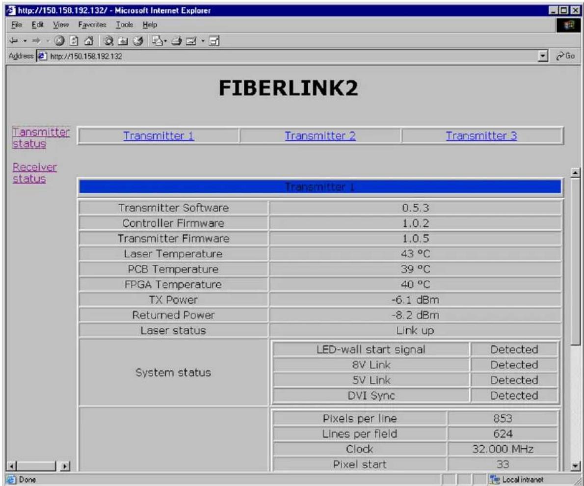
Image 6-1
6.2 Software update
Software for Fiberlink 2
Software and firmware (flash) of the Fiberlink 2 base unit, transmitter and receiver can be updated in the field if required. New releases of flash software are available on the "Partner Zone" of the Barco web site www.barco.com. Refer to the user guide of the control software (e.g. Director toolset) for upload instructions of new versions.
A. DIMENSIONS
About this chapter
This chapter contains the drawings of the Fiberlink 2 components with most of the external dimensions.
Overview
• Dimensions of the Fiberlink 2 base unit
- Dimensions of the Fiberlink 2 transmitter unit
• Dimensions of the Fiberlink 2 receiver
A.1 Dimensions of the Fiberlink 2 base unit
Dimensions base unit

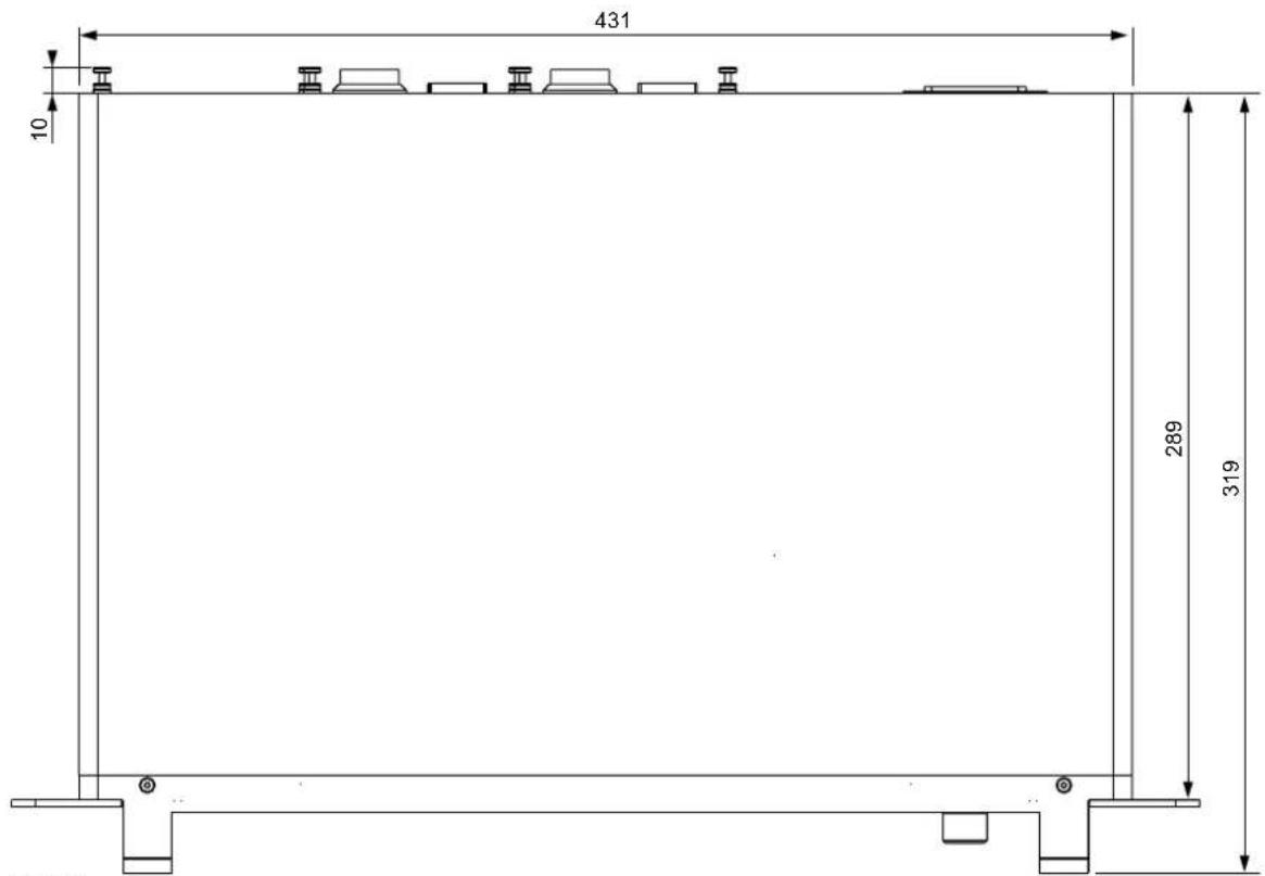
Image A-1 Dimensions given in millimeters.
A.2 Dimensions of the Fiberlink 2 transmitter unit
Dimensions transmitter unit
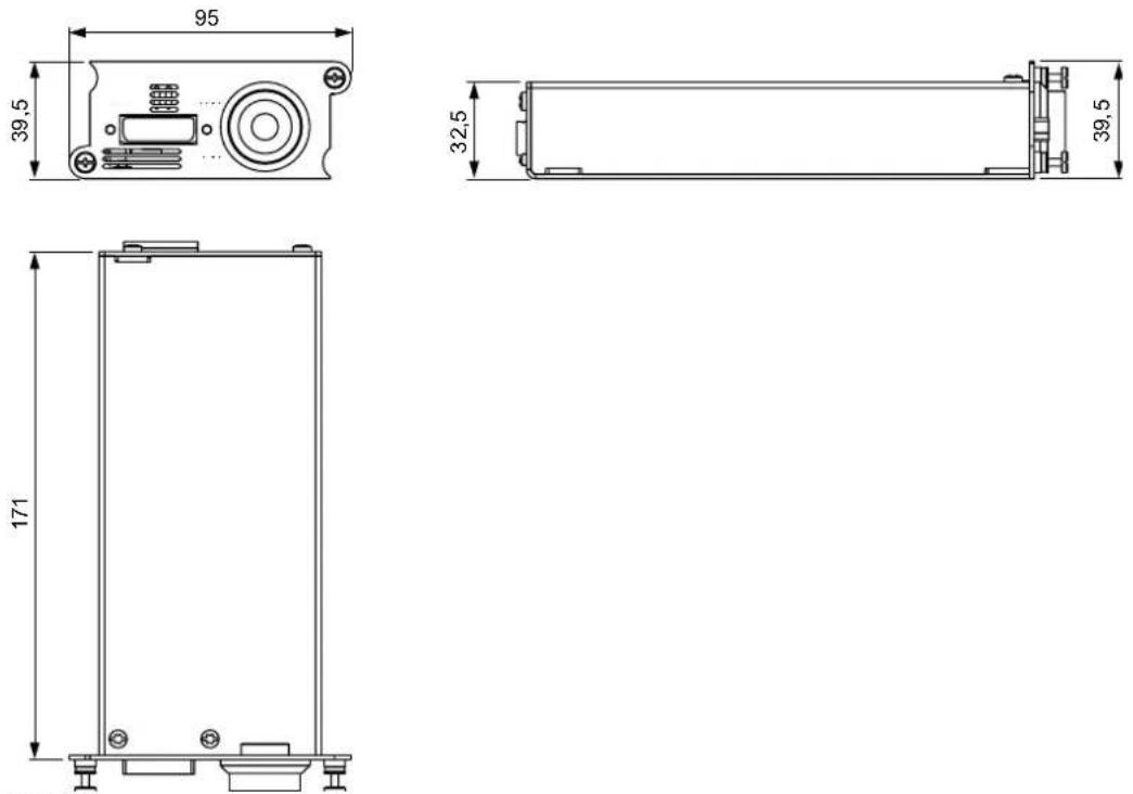
Image A-2
Dimensions given in millimeters.
A.3 Dimensions of the Fiberlink 2 receiver
Dimensions receiver
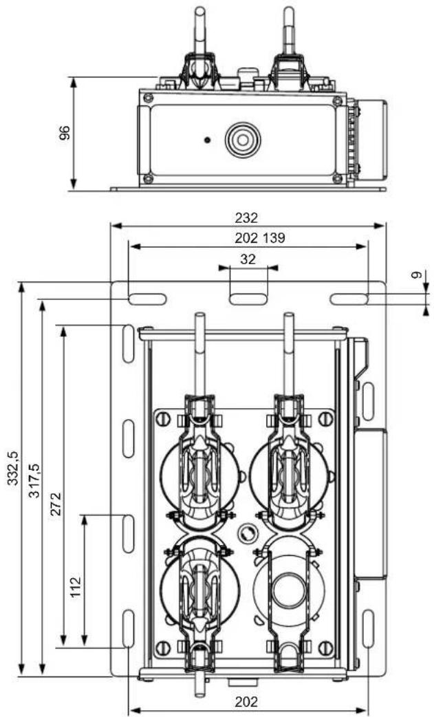
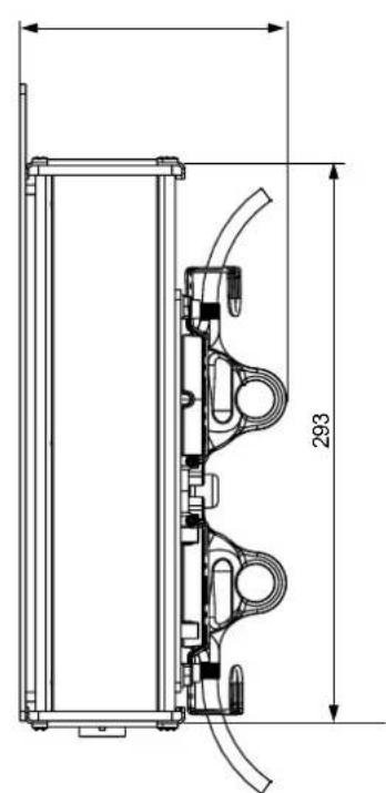
Image A-3
Dimensions given in millimeters.
B. SPECIFICATIONS
About this chapter
This chapter contains a list with the specifications of the Fiberlink 2 system.
Overview
- Fiberlink 2 specifications
B.1 Fiberlink 2 specifications
Specifications
Reach
Multimode up to 500 m (984 ft)
Single Mode up to 5000 m (16404 ft)
Transmitter
- 19 inch rack compatible base unit (1U height)
• Modulair fiber channel system. Up to three channels per base unit.
• Auto ranging power supply between 90 and 132 volt and between 180 and 264 volt (50-60 Hz). - Operating Temperature 0 - 40°C (32 - 104°F).
• Controlled and configured via control software (e.g. XLite toolset or Director toolset).
• Built in user interface to control most basic functionality.
• Built in pattern generator.
• DVI-D input per transmitter unit. - No frame delay.
• Supports RS422 communication up to 115200 baud (9600 baud on Fiberlink I). - Field upgradeable over TCP/IP or USB (USB-B).
- Power cosumption base unit: 50 watt maximum.
• Built in fiber test ("ping").
• Optical transceiver with robust LEMO® connectors.
Receiver
• Auto ranging power supply 190-264 volt (50-60 Hz).
- Operating Temperature -20 - 50°C (-4 - 122°F).
• Compact receiver unit sheltered in an IP65 rated housing.
• Controlled and configured via control software (e.g. XLite toolset or Director toolset).
• Built in pattern generator.
- No frame delay.
• Supports RS422 communication up to 115200 baud (9600 baud on Fiberlink I).
- Field upgradeable over TCP/IP or USB (USB-B).
- Power consumption receiver unit: 50 watt maximum.
• Built in fiber test ("ping").
- Optical transceiver with robust LEMO® connectors.
C. ORDER INFO
About this chapter
This chapter contains a list with the ordering code of the different components of the Fiberlink 2 system.
Overview
- Order info
C.1 Order info
Order info
| Order No. | Description |
| R9853350 Fiberlink 2 | base unit. |
| R9853360 | Fiberlink 2 long distance (LD) receiver (up to 5 kilometer) for single mode optical fiber. |
| R9853361 | Fiberlink 2 short distance receiver (up to 500 meter) for multi mode optical fiber. |
| R9853370 | Fiberlink 2 long distance (LD) transmitter input (up to 5 kilometer) for single mode optical fiber. |
| R9853371 | Fiberlink 2 short distance transmitter input (up to 500 meter) for multi mode optical fiber. |
| R9850430 | 50 meter multi mode optical fiber cable with LEMO® connectors. |
| R9850431 | 100 meter multi mode optical fiber cable with LEMO® connectors. |
| R9850432 | 150 meter multi mode optical fiber cable with LEMO® connectors. |
| R9850433 | 200 meter multi mode optical fiber cable with LEMO® connectors. |
| R9850434 | 250 meter multi mode optical fiber cable with LEMO® connectors. |
| R9850435 | 300 meter multi mode optical fiber cable with LEMO® connectors. |
| R9850436 | Custom made multi mode optical fiber cable. |
| R9850481 | Custom made single mode optical fiber cable. |
INDEX
A
AL 32–33
AP 31, 33
B
Base unit 12, 20, 46
Bit rate 31
Byte level 33
C
Cables 9
CLK 31
Color pattern 34
Color porch 34
Components 9, 11
D
Data cables 17
DHCP 36
Diagnoses 42
TCP/IP 42
Diagnostic 30
Dimensions 45–48
Base unit 46
Receiver 48
Transmitter unit 47
DUAL Path 33
DVI timings 31
E
Ethernet 32, 36
Configuration 36
Ethernet enable 36
F
Firmware input 30
Firmware RX 30
Firmware TX 30
FPGA temp 32
Full install 25
Functionality 9
G
General info 7
GW address 32
H
H Left 34
H Motion 34
HS-Width 33
|
Install 20, 22
Base unit 20
Receiver 22
Transmitter unit 20
Installation 19
Introduction 8
IP address 32
L
Laser info 31
Laser power 30
Laser temp 32
Laser vendor 31
LED-wall 35
ON/OFF 35
Length 50/125 31
Length 62.5/125 31
Length 9/125 31
LPF 31, 33
LS 32-33
M
MAC address 32
Main menu 28
Maintenance 41
Menu 30, 33
Diagnostic 30
Pattern GEN 33
Messages 37
Error 37
Mounting positions 24
Receiver 24
Multi mode 8
N
NM address 32
0
Optical fiber cables 15
Order info 51–52
Outline 33
P
Pattern enable 33
Pattern GEN 33
Pattern motion 34
Pattern type 33
Power cables 17
Power in 30
Power out 30
PPL 31, 33
PPL Last Line 32
PS 31, 33
Purpose 8
R
Receiver 22, 48
Receivers 14
S
Safety 3–4
Instructions 4
Single mode 8
SINGLE Path 33
Software RX 30
Software TX 30
Software update 43
Specifications 49–50
Static GW 36
Static IP 36
Static NM 36
Status RX 30
Status TX 30
System overview 9
T
Temperature 32
Transmitter unit 20, 47
Transmitters 13
U
User interface 27
V
VMotion 34
VUp 34
Versions 30
VS Width 33
Vsync 32
W
Warnings 5
Wavelength 31
Width 33
- Changes
- Copyright ©
- Federal Communications Commission (FCC Statement)
- Guarantee and Compensation
- Trademarks
- TABLE OF CONTENTS
- Safety....3
- General....7
- System components....11
- Installation....19
- User interface 27
- Maintenance....41
- Dimensions ....45
- Specifications ....49
- Order info 51
- Index....53
- SAFETY
- About this chapter
- Overview
- Important safety instructions
- Instructions:
- Important warnings
- Important warnings
- - Risk of electric shock:
- • Class 1 laser product:
- CLASS 1 LASER PRODUCT TO IEC 825
- • Maximum and minimum ambient temperature:
- - Ventilation:
- - Flammable materials:
- • This equipment MUST be earthed:
- - Power system:
- - Disconnect device:
- - Mains cords:
- - Rack mounting:
- • Cabinet openings:
- - Replacement parts:
- - Safety check:
- GENERAL
- Fiberlink 2
- Introduction
- Purpose
- Multi- or single- mode ?
- Functionality
- System overview
- SYSTEM COMPONENTS
- Base unit
- Connector sockets and input slots of the Fiberlink 2 base unit
- Transmitters
- Receivers
- Mounting plate and connector sockets of a Fiberlink 2 receiver
- Optical fiber cables
- Which optical fiber cable to use?
- Pre-installed optical fiber network
- Power and data cables
- General
- INSTALLATION
- Installing the Fiberlink 2 base unit
- What has to be done?
- Necessary tools
- Necessary parts
- How to install the Fiberlink 2 base unit and transmitter unit(s)?
- Installing the Fiberlink 2 receiver
- How to install the Fiberlink 2 receiver?
- Other mounting positions of the Fiberlink 2 receiver
- Example of other mounting positions of the Fiberlink 2 receiver
- Full installation example
- Full installation example
- USER INTERFACE
- Using the jog dial
- Activating the user interface
- Main menu structure
- Overview "Main menu"
- - Pattern GEN
- - TX
- - RX
- - LED-wall
- "Diagnostics" menu description
- Diagnostics > Versions > TX Software
- Diagnostics > Versions > TX Firmware
- Diagnostics > Versions > TX Input
- Diagnostics > Versions > RX Software
- Diagnostics > Versions > RX Firmware
- Diagnostics > Laser > TX Status
- Diagnostics > Laser > RX Status
- Diagnostics > Laser > Power > TX → power out
- Diagnostics > Laser > Power > TX → power in
- Diagnostics > Laser > Power > RX → power out
- Diagnostics > Laser > Power > RX → power in
- "Pattern GEN" menu description
- Pattern GEN > TX (RX) > Enable Patt
- "LED-wall" menu description
- "Ethernet conf" menu description
- Ethernet conf > Enable eth
- Ethernet conf > DHCP
- Ethernet conf > Static IP
- Ethernet conf > Static NM
- Ethernet conf > Static GW
- Fiberlink 2 messages (apart from menu messages)
- When booting
- When failed to setup Ethernet
- When uploading to flash
- DVI sync information
- TX laser status
- MAINTENANCE
- Diagnoses via TCP/IP
- How to retrieve information of the Fiberlink 2 via TCP/IP?
- Software update
- Software for Fiberlink 2
- DIMENSIONS
- A.1 Dimensions of the Fiberlink 2 base unit
- A.2 Dimensions of the Fiberlink 2 transmitter unit
- A.3 Dimensions of the Fiberlink 2 receiver
- SPECIFICATIONS
- B.1 Fiberlink 2 specifications
- Specifications
- Reach
- Transmitter
- Receiver
- ORDER INFO
- C.1 Order info
- INDEX
- A
- B
- C
- D
- E
- F
- G
- H
- |
- L
- M
- N
- 0
- P
- R
- S
- T
- U
- V
- W
Brand : Barco
Model : R9853370
Category : Projector accessory