
NE-24A-B - Lighting PATLITE - Free user manual and instructions
Find the device manual for free NE-24A-B PATLITE in PDF.


| Product Type | Signal Light / Industrial Lighting |
| Brand | PATLITE |
| Model | NE-24A-B |
| Voltage | 24V DC |
| Color | Red (based on model example) |
| Mounting Hole Diameter | 4.5 mm |
| Indoor Use Only | Yes |
| Waterproof Protection | Waterproof sheet included (1mm thick), sealant recommended |
| Terminal Type | Screwless terminal block (non-polarity) |
| Wire Stripping Length | 8 mm |
| Cable Gland Recommendation | M16x1.5, screw length <11mm, outer diameter <25mm, plastic |
| Globe Locking | Rotate clockwise to lock, counterclockwise to unlock |
| Cleaning | Soft cloth moistened with water (no thinner, benzine, gasoline, oil) |
| Fuse Requirement | Must be added in the wiring circuit between power source and equipment |
| Safety Compliance | CE, FCC Class A, RoHS, KC, UL/CSA |
| Installation Surface | Slurry surface, level, with sealant around wire exit |
| Operating Temperature | Not specified, assume typical industrial range (e.g., -20°C to 50°C) |
| Weight | Approx. 150 g (estimate) |
| Dimensions (Body) | Approx. 50 mm diameter x 70 mm height (estimate) |
| Repair and Maintenance | Replace damaged globe or case; daily inspection for security use |
| Driving Method | External contact drive, NPN/PNP transistor drive |
Frequently Asked Questions - NE-24A-B PATLITE
User questions about NE-24A-B PATLITE
0 question about this device. Answer the ones you know or ask your own.
Ask a new question about this device
Download the instructions for your Lighting in PDF format for free! Find your manual NE-24A-B - PATLITE and take your electronic device back in hand. On this page are published all the documents necessary for the use of your device. NE-24A-B by PATLITE.
USER MANUAL NE-24A-B PATLITE
Notice to Customer Thank you very much for purchasing our Patlite products.
- Request the installation and wiring to be performed by a professional contractor if construction work is involved.
• Prior to installation, read this
- Prior to installation, read this manual thoroughly before using this product to ensure correct use. - In addition, please store this manual for future reference when performing maintenance repairs.
- Visit our homepage (https://www.patlite.com/) and download the "Complete Operation Manual: NE-24A" to
find out more about the operating method and features.
- If there are any questions concerning this product, refer to the contact information at the end of this document and contact your nearest PATITE Sales Representative.
contact your nearest PATELL Sales Representative
CE Marking
- This product conforms to EN standards and shows the CE Marking. This product has been tested and found to comply with the limits for a Class A device, pursuant to EMC DIRECTIVE. These limits are designed to provide reasonable protection against harmful interference when the equipment is operated in a commercial environment. This product must not be used in residential areas.
1 Read this First (Safety Precautions)
Warning Failure to observe the following may result in death or serious injury.
• To prevent from short-circuits or damage, observe the following:
- Be sure the power is disconnected before replacement or repair, including the replacement of the fuse. - Use this product in a properly maintained condition. (Replace or repair if the globe, case, etc. are damaged.) - If installing this product requires construction work, ask a specialist in order to avoid fire, or personal injury. - When this product is used for security purposes, it should be inspected daily. In case a malfunction should occur, it is recommended that you use this product together with other security products.
- After installation, do not use this product to climb up onto the equipment with. Failure to comply will result in product damage and/or falling off the machinery.
(1) = =

- Be sure to put a fuse in the wiring circuit between the power source and equipment for protection. If a fuse is not added, it
may result in product and/or equipment failure.
- Be sure to prevent electrostatic damage due to discharge when working with this product for wiring, exchanging units,
setting up parameters, etc. by discharging static electricity on your body, etc.
- Do not disassemble or detach during operation - Do not push on any internal ports when wiring
- DO NOT PUSH ON ANY INTERNAL PARTS WHEN WIRING.
2 Model Number Configuration

Model Number Example
• 24 V DC • Rec
3 Part Names and Outer Appearance
Unit: mm


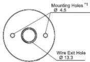
Bottom View
(Without waterproof sheet)
*1 Drill the mounting holes (∅4.5) from the top.
-4-
4 Installation
* The following requirements are necessary for proper installation:
- Install the signal light where excessive vibration is not present. Install the signal light on a sturdy surface
- Install the signal light on a sturdy surface - Install the signal light on a level surface.
* When it is necessary to waterproof the backside of the installation
When it is necessary, to transpose the sections of the installation surface;
- Provide a sealant coating around the nuts of the backside of the
installation surface
- Provide a sealant coating around the wire exit hole, or use a
Cable Gland.
* After locking the globe, check that there is no gap between globe
and body. Being a gap may cause water intrusion or falling off the
globe.
(1) Unlock the globe by holding and rotating it in a
counter-clockwise direction, then lift it up.
(2) Drill the mounting holes(Ø4.5) from the top on the case.
(3) Peel off the adhesive paper from the waterproc apply it to the case.
(4) Affix the product to the installation surface with screws and nuts.
(4) A mix the product to the installation surface with screws and nuts. (Installation screws and nuts are not included with this product.)
(5) After mounting the case, fit the globe by aligning the positioning
marks and lock it by rotating in a clockwise direction.
■Installation Dimensions
Unit : mm
Wire Exit Hole
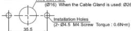
* When the Cable Gland is used, the hole must be large enough for it to fit through
The recommended Cable Gland size is as follows:
screw size: M16x1.5; screw length: shorter than 11mm; outer diameter: less than 35mm;
outer diameter: less than 25mm, material: plastic. (Torque : 3N·m)
- This product is for indoor use only. (Do not use it outdoor.)
Caution • This product is for indoor use only. (Do not use it outdoors. • Do not leave the product, or use it without globe installed
- Do not apply excessive force when mounting/removing the globe. Failure to comply will result in damage. - Use a soft cloth moistened with water to clean the globe or case. (Do not use thinner, benzine, gasoline or oil.) - The waterproof sheet must be used before installation.
- This product has a 1mm thick waterproof sheet at the bottom of the case. However, because installation surface
unevenness may cause a lack of waterproofing protection, it is recommended to apply sealant between the unit
and the installation surface to maintain waterproof conditions.
5 Wiring
5 wiring
(1) Remove the globe by unscrewing it in a counter-clockwise
direction. (2) Connect the wires to the screwless terminal block.
(2) Connect the wires to the screwless terminal block. (3) Attach the globe by screwing it in a clockwise direction
* The terminals have no polarity.
Screwless Terminal Block wiring method


- Caution • Make sure the power is OFF before wiri
Caution • Ensure the proper working voltage is used. Improper voltage will damage internal circuit
- Do not pull the wire out or push it into the case.
- Be sure the wiring is done properly. Any mistake in wiring may result in damage.
- Be sure to put a fuse in the wiring circuit between the power source and equipment for protection. If a fuse is not
added, it may result in product and/or equipment failure.
- Do not apply excessive force to the screwless terminal block during wiring. It will be the cause of the failure
M
Make sure that the wires do not sag internally. There is a risk that the light intensity may be reduced by hitting the LED.
10.14.2023
Wiring Example
Wiring examples vary depending on the driving method.

flowchart
graph TD
    A["(A) External Contact Drive"] --> B["External Contact"]
    B --> C["Fuse 1A"]
    C --> D["Power Supply (Non-polar)"]
    D --> E["I/O Unit"]
    F["(B) I/O Unit Drive (NPN Transistor)"] --> G["Fuse 1A"]
    G --> H["Power Supply (DC24V)"]
    H --> I["I/O Unit"]
    J["(C) I/O Unit Drive (PNP Transistor)"] --> K["Fuse 1A"]
    K --> L["Power Supply (DC24V)"]
    L --> M["I/O Unit"]

-5-
6 仕様
● UL508, CSA-C22.2 No.14
KC (KN61000-6-4, KN61000-6-2)
● RoHS指令 (EN50581)
● FCC Part 15 Subpart B Class A
● 低電圧指令(IEC/EN60947-5-1,EN62471)
| Model | NE-24A _C |
| Rated Voltage | 24V DC (Non-polar) |
| Current Consumption (Max.) | 26mA |
| Mounting Direction | All Directions |
| Operating Temperature Range(Relative Humidity) | -30°C ++50°C(Less than 90%RH, Non-condensation) |
| Protection Rating | IP 65 ^TM NEMA TYPE 4X, 13 |
| Mass | 0.06kg |
*1 Condition to satisfy IP66/67: Only when this product is installed with a Cable Gland on a flat surface.
- Conformity Standards
• EMC Directive (EN61000-6-4, EN61000-6-2)
• UL508, CSA-C22.2 No.14
- KC (KN61000-6-4, KN61000-6-2)
• Low Voltage Directive (IEC/EN60947-5-1, EN62471)
• Conformity requirements for the UL Standard:
• Maximum surrounding air temperature rating of 50 °C
• This product is designed for use on a flat surface for a Type 1 Enclosure.
- Use a "class 2" power supply specified in the guidelines under UL1310.
• For use in Pollution Degree 2 Environment • Conformity requirements for the CE Marking:
- Conformity requirements for the CE Marking. This product conforms to EN standards and shows the CE Marking
This product conforms to EN standards and shows the CE marking. This product has been tested and found to comply with the limits for a Class A device, pursuant to EMC
DIRECTIVE. These limits are designed to provide reasonable protection against harmful interference when the
equipment is operated in a commercial environment. This product must not be used in residential areas.
• Conformity to FCC Compliance
This equipment has been tested and found to comply with the limits for a Class A digital device, pursuant to Part 45 of the 500 Rules. These limits are designed to provide reasonable protection against harmful interference.
Part 15 of the FCC Rules. These limits are designed to provide reasonable protection against harmful interference when the equipment is operated in a commercial environment. The equipment generates uses and can radiate
when the equipment is operated in a commercial environment. The equipment generates, uses, and can radiate radio frequency energy and, if not installed and used in accordance with the instruction manual, may cause
radio frequency energy and, if not installed and used in accordance with the instruction manual, may cause harmful interference to radio communications. Operation of this equipment in aresidential area is likely to cause
harmful interference in which case the user will be required to correct the interference at his own expense.
(Note) · Dimensions and specifications may change without notice due to
continual product improvement.
• PATLITE and the PATLITE logo is a trademark, or registered
trademark of the PATLITE Corporation of Japan and each country.
(Importer for EU)
PATLITE Europe GmbH Am Soeldnermoos 8, D-85399 Hallbergmoos, Germany
• RoHS Directive (EN50581)
• FCC Part 15 Subpart B Class A
[Non-Text]
71)
[Non-Text]
PATLITE®
Signalleuchte
The following table provides the original data:
The Ground Truth image displays a single, solid horizontal line, which is a stylistic or background element (like a rule line on paper). According to Rule 2, such lines must be ignored by the OCR result. The OCR content provided is "", which consists of no characters. Since the OCR output correctly ignores the stylistic line, it complies with the “Stylistic/Background Lines (Ignore)” rule. Therefore, the OCR result is consistent with the Ground Truth.
The Ground Truth image displays a single, solid horizontal line. According to Rule 2 (UNDERSCORE & LINE RULES), this is a stylistic or background line, not a placeholder underscore. Therefore, the OCR result must ignore it and output nothing or only meaningful text. The provided OCR content is "____", which consists of four underscores. This is an incorrect interpretation of the line as a placeholder, violating the rule that stylistic lines must be ignored. The OCR has hallucinated underscores where none should exist based on the GT's visual context. Hence, the OCR result is inconsistent with the Ground Truth.
The Ground Truth image displays a single, solid horizontal line. According to Rule 2 (UNDERSCORE & LINE RULES), this is a stylistic or background line, not a placeholder underscore. Therefore, the OCR result must ignore it and output nothing or only meaningful text. The provided OCR content is "____", which consists of four underscores. This is an incorrect interpretation of the line as a placeholder, violating the rule that stylistic lines must be ignored. The OCR has hallucinated underscores where none should exist based on the GT's visual context. Hence, the OCR result is inconsistent with the Ground Truth.
2017年1月1日
i [Sicherung]


Brand : PATLITE
Model : NE-24A-B
Category : Lighting