G0555P - Saw Grizzly - Free user manual and instructions
Find the device manual for free G0555P Grizzly in PDF.

| Product Type | 14" Bandsaw |
| Brand | Grizzly |
| Model | G0555P |
| Motor Power | 1 HP (110V/220V, 60 Hz) |
| Blade Length | 93.5 inches |
| Blade Width Range | 1/8" to 3/4" |
| Cutting Capacity (Height) | 6 inches |
| Cutting Capacity (Throat) | 13.5 inches |
| Table Size | 14 x 14 inches |
| Table Tilt | 45° right |
| Overall Dimensions (L x W x H) | 30 x 20 x 66 inches |
| Weight | 185 lbs |
| Power Source | Electric, 115V/230V |
| Amperage | 6.3A @ 115V |
| Blade Speed | 1520 FPM (fixed) |
| Dust Port | 4 inches |
| Main Features | Cast iron frame, quick-release blade tension, miter gauge |
| Maintenance | Periodic blade cleaning, bearing lubrication, belt tension check |
| Safety | Blade guard, push stick, emergency stop |
| Spare Parts Availability | Replacement blades, tires, bearings, belts available |
| Repairability | DIY-friendly with detailed manual and online support |
| Certifications | UL listed, CE compliant |
Frequently Asked Questions - G0555P Grizzly
User questions about G0555P Grizzly
0 question about this device. Answer the ones you know or ask your own.
Ask a new question about this device
Download the instructions for your Saw in PDF format for free! Find your manual G0555P - Grizzly and take your electronic device back in hand. On this page are published all the documents necessary for the use of your device. G0555P by Grizzly.
USER MANUAL G0555P Grizzly
Grizzly Industrial, Inc.®
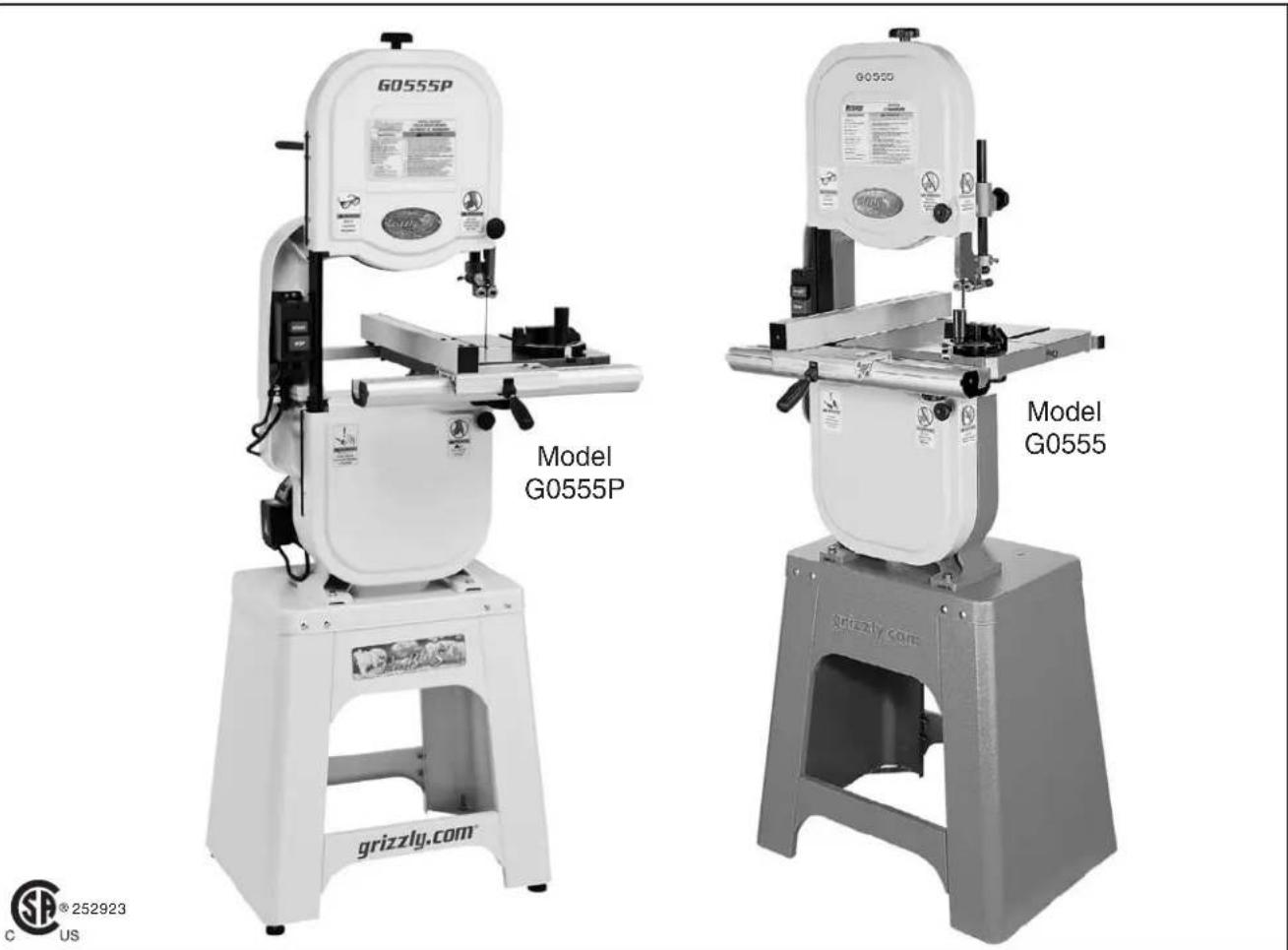
MODEL G0555/G0555P ULTIMATE 14" BANDSAW
OWNER'S MANUAL
text_image
G0555P Model G0555P G0555 Model G0555 grizzly.com grizzly.com © 252923 C USCOPYRIGHT © AUGUST, 2002 BY GRIZZLY INDUSTRIAL, INC., REVISED SEPTEMBER, 2017 (AB)
WARNING: NO PORTION OF THIS MANUAL MAY BE REPRODUCED IN ANY SHAPE
OR FORM WITHOUT THE WRITTEN APPROVAL OF GRIZZLY INDUSTRIAL, INC.
FOR MODELS MANUFACTURED SINCE 5/11 #TR4508 PRINTED IN TAIWAN

WARNING!
This manual provides critical safety instructions on the proper setup, operation, maintenance, and service of this machine/tool. Save this document, refer to it often, and use it to instruct other operators.
Failure to read, understand and follow the instructions in this manual may result in fire or serious personal injury—including amputation, electrocution, or death.
The owner of this machine/tool is solely responsible for its safe use. This responsibility includes but is not limited to proper installation in a safe environment, personnel training and usage authorization, proper inspection and maintenance, manual availability and comprehension, application of safety devices, cutting/sanding/grinding tool integrity, and the usage of personal protective equipment.
The manufacturer will not be held liable for injury or property damage from negligence, improper training, machine modifications or misuse.

WARNING!
Some dust created by power sanding, sawing, grinding, drilling, and other construction activities contains chemicals known to the State of California to cause cancer, birth defects or other reproductive harm. Some examples of these chemicals are:
- Lead from lead-based paints.
- Crystalline silica from bricks, cement and other masonry products.
- Arsenic and chromium from chemically-treated lumber.
Your risk from these exposures varies, depending on how often you do this type of work. To reduce your exposure to these chemicals: Work in a well ventilated area, and work with approved safety equipment, such as those dust masks that are specially designed to filter out microscopic particles.
Table of Contents
INTRODUCTION....2
Manual Accuracy 2
Contact Info.... 2
Machine Description 2
Identification 3
Machine Data Sheet 4
SECTION 1: SAFETY....6
Safety Instructions for Machinery 6
Additional Safety for Bandsaws 8
SECTION 2: POWER SUPPLY....9
SECTION 3: SETUP 12
Needed for Setup 12
Unpacking 12
Hardware Recognition Chart 13
Inventory 14
Cleanup 15
Site Considerations 16
Assembly 17
Blade Center Tracking 21
Dust Collection 22
Power Connection.... 23
Test Run 23
Tensioning Blade 24
Adjusting Blade Support Bearings 25
Adjusting Blade Guide Bearings 26
Table Tilt Calibration 28
Aligning Table 29
Aligning Fence 30
SECTION 4: OPERATIONS ...... 31
Operation Overview 31
Disabling & Locking Switch.... 32
Workpiece Inspection.... 32
Guide Post 33
Table Tilt 33
Blade Speed 34
Blade Information 35
Blade Change 37
Basic Cutting Tips 38
Cutting Options 38
Ripping 38
Crosscutting 39
Resawing 39
Cutting Curves 40
Stacked Cuts.... 40
SECTION 5: ACCESSORIES....41
SECTION 6: MAINTENANCE....43
Schedule 43
Cleaning & Protecting 43
Lubrication 44
Redressing Rubber Tires 44
SECTION 7: SERVICE 45
Troubleshooting 45
V-Belt Tension 47
Replacing V-Belt 48
Shimming Table 48
Wheel Alignment 49
Blade Lead 52
Blade Tensioner 53
Fence Scale Calibration 54
SECTION 8: WIRING....55
Wiring Safety Instructions 55
Wiring Diagram 56
SECTION 9: PARTS....57
Main 57
Stand 60
Fence 61
Labels 62
WARRANTY AND RETURNS 65
Manual Accuracy
We are proud to provide a high-quality owner manual with your new machine!
We made every effort to be exact with the instructions, specifications, drawings, and photograph in this manual. Sometimes we make mistakes, but our policy of continuous improvement also means that sometimes the machine you receive is slightly different than shown in the manual.
If you find this to be the case, and the difference between the manual and machine leaves you confused or unsure about somethingcheck our website for an updated version. We post current manuals and manual updates for free on our website at www.grizzly.com.
Alternatively, you can call our Technical Support for help. Before calling, make sure you write down the Manufacture Date and Serial Number from the machine ID label (see below). This information is required for us to provide proper tech support, and it helps us determine if updated documentation is available for your machine.

text_image
Grizzly industrial MODEL GXXXX MACHINE NAME SPECIFICATIONS WARNING! To reduce risk of serious injury when using this machine: Motor: Specification: Specification: Specification: Specification: Weight: Date Manufactured for Grizzly in Taiwan Manufacture Date To reduce risk of serious injury when using this machine: Manual before operation. Safety glasses and respirator. Directly adjusted/setup and power is connected to grounded circuit before starting. Make sure the motor has stopped and disconnect power before adjustments, maintenance, or service. DO NOT expose to rain or dampness. DO NOT modify this machine in any way. 7. 8. 9. 10. Maintain machine carefully to prevent accidents. Serial Number Jended. e of drugs or alcohol.Contact Info
We stand behind our machines! If you have questions or need help, contact us with the information below. Before contacting, make sure you get the serial number and manufacture date from the machine ID label. This will help us help you faster
Grizzly Technical Support
1815 W. Battlefield
Springfield, MO 65807
Phone: (570) 546-9663
Email: techsupport@grizzly.com
We want your feedback on this manual. What did you like about it? Where could it be improved. Please take a few minutes to give us feedback.
Grizzly Documentation Manager
P.O. Box 2069
Bellingham, WA 98227-2069
Email: manuals@grizzly.com
Machine Description
The bandsaw is a versatile woodworking tool that is used to perform a wide variety of cuts in wood stock, such as rip cuts, cross cuts, bevel cuts, miter cuts, circular cuts, contour cuts, stacked pattern cuts, etc.
The bandsaw blade is a continuous metal band wrapped around two rotating wheels, which performs the cut as it passes through the workpiece and table. Adjustable blade guide and support bearings keep the blade in position during this operation.
The included adjustable fence, miter gauge, and tilting table support a wide variety of cutting operations.
Note: The Polar Bear Model G0555P is the same machine as the Model G0555 except for the brilliant white color.
Identification
text_image
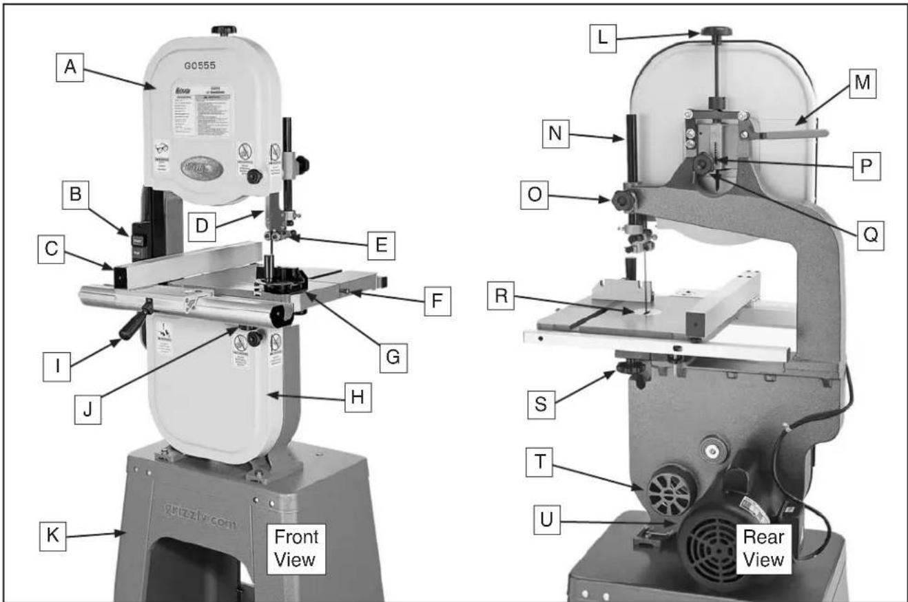
G0555 A B C D E F I J G H K Front View L M N O P Q R S T U Rear ViewFigure 1. G0555 G0555P identification.
A. Upper Wheel Cover
B. ON/OFF Switch w/Disabling Padlock
C. Fence
D. Blade Guard
E. Upper Blade Guide Assembly
F. Table Pin
G. Miter Gauge Assembly
H. Lower Wheel Cover
I. Fence Lock Lever
J. Front Table Lock Knob
K. Stand Assembly
L. Blade Tension Adjustment Knob
M. Blade Tension Quick Release Lever
N. Guide Post
O. Guide Post Lock Knob
P. Blade Tension Scale
Q. Blade Tracking Adjustment Knob
R. Table Insert
S. Rear Table Lock Knob
T. 4" Dust Port
U. Motor
natural_image
Illustration of a hand pointing at an open book (no text or symbols visible)WARNING
To reduce your risk of serious injury, read this entire manual BEFORE using machine.
Grizzly Industrial, Inc.
MACHINE DATA SHEET
© Grizzly Industrial, Inc. • Customer Service: (800) 523-4777 • Website: www.grizzly.com
MODEL G0555/G0555P ULTIMATE 14" BANDSAW
Product Dimensions:
Weight 167 lbs.
Length/Width/Height 26 ^3/8 " x 30 ^1/4 " x 66 ^1/2 "
Foot Print (Length/Width)....24 ^1/2 " x 17 ^1/2 "
Shipping Dimensions:
Type Cardboard
Content....Machine
Weight....198 lbs.
Length/Width/Height....44" x 21" x 20"
Electrical:
Switch.... On/Off Push Button
Switch Voltage 110/220V
Cord Length 6 ft.
Cord Gauge ....16 gauge
Minimum Circuit Size 15A @ 110V, 10A @ 220V
Plug Included ....Yes
Recommended Plug Type ......NEMA 6-15 @220V
Included Plug Type NEMA 5-15
Motors:
Main
Type TEFC Capacitor Start Induction
Horsepower....1 HP
Voltage....110V/220V
Prewired....110V
Phase....Single
Amps 11/5.5A
Speed....1725 RPM
Cycle 60 Hz
Number Of Speeds 1
Power Transfer....Belt Drive
Bearings....Shielded and Lubricated
Main Specifications:
Operation Information
Blade Speed....1500, 3200 FPM
Table Tilt....Left 10°, Right 45°
Cutting Capacities
Maximum Cutting Height 6"
Max Capacity Left of Blade 13 ^1/2 "
Blade Information
Standard Blade Length....93 ^1/2 "
Blade Length Range....92 ^1/2 “-93 ^1/2 ”
Blade Width Range 18 “ 34 ”
Upper Blade Guides....Anti-Collision Ball Bearing
Lower Blade Guides....Anti-Collision Ball Bearing
Guide Post Size....0.865" (22mm)
Guide Post Type...... Solid Steel
Table Information
Table Length 14"
Table Width 14"
Table Thickness 1½"
Floor to Table Height....43 ^5/16 "
Fence Information
Locks in Front......Yes
Locks in Rear No
Adjustable for Blade Lead....Yes
Construction
Table Construction ...... Precision Ground Cast Iron
Rip Fence ...... Deluxe Extruded Aluminum
Base Construction Pre-Formed Steel
Body Construction Cast Iron
Upper Wheel ...... Computer Balanced Cast Aluminum
Lower Wheel ...... Computer Balanced Cast Aluminum
Tire Material ....Rubber
Wheel Cover Pre-Formed Steel
Paint Powder Coated
Other Related Information
Wheel Diameter....13 ^3/4 "
Wheel Width 1 ^3/16
Number of Dust Ports 1
Dust Port Size 4"
Mobile Base......G7314Z
Other Specifications:
ISO Factory....ISO 9001
Country Of Origin....Taiwan
Warranty....1 Year
Serial Number Location ID Label on Upper Wheel Cover
Customer Setup and Cleaning Time....1½ Hours
Features:
Includes Fence and Miter Gauge
Upper and Lower Ball Bearing Blade Guides
Deluxe Heavy-Duty Stand
Magnifying Window Over Fence Scale
Hinged Wheel Covers
4" Dust Port
6" Riser Block Available
For Your Own Safety, Read Instruction Manual Before Operating This Machine
The purpose of safety symbols is to attract your attention to possible hazardous conditions. This manual uses a series of symbols and signal words intended to convey the level of importance of the safety messages. The progression of symbols is described below. Remember that safety messages by themselves do not eliminate danger and are not a substitute for proper accident prevention measures. Always use common sense and good judgment.

Indicates an imminently hazardous situation which, if not avoided, WILL result in death or serious injury.

Indicates a potentially hazardous situation which, if not avoided, COULD result in death or serious injury.

Indicates a potentially hazardous situation which, if not avoided, MAY result in minor or moderate injury. It may also be used to alert against unsafe practices.
NOTICE
This symbol is used to alert the user to useful information about proper operation of the machine.
Safety Instructions for Machinery
WARNING
OWNER'S MANUAL. Read and understand this owner's manual BEFORE using machine.
TRAINED OPERATORS ONLY. Untrained operators have a higher risk of being hurt or killed. Only allow trained/supervised people to use this machine. When machine is not being used, disconnect power, remove switch keys, or lock-out machine to prevent unauthorized use—especially around children. Make your workshop kid proof!
DANGEROUS ENVIRONMENTS. Do not use machinery in areas that are wet, cluttered, or have poor lighting. Operating machinery in these areas greatly increases the risk of accidents and injury.
MENTAL ALERTNESS REQUIRED. Full mental alertness is required for safe operation of machinery. Never operate under the influence of drugs or alcohol, when tired, or when distracted.
ELECTRICAL EQUIPMENT INJURY RISKS. You can be shocked, burned, or killed by touching live electrical components or improperly grounded machinery. To reduce this risk, only allow qualified service personnel to do electrical installation or repair work, and always disconnect power before accessing or exposing electrical equipment.
DISCONNECT POWER FIRST. Always disconnect machine from power supply BEFORE making adjustments, changing tooling, or servicing machine. This prevents an injury risk from unintended startup or contact with live electrical components.
EYE PROTECTION. Always wear ANSI-approved safety glasses or a face shield when operating or observing machinery to reduce the risk of eye injury or blindness from flying particles. Everyday eyeglasses are NOT approved safety glasses.
WARNING
WEARING PROPER APPAREL. Do not wear clothing, apparel or jewelry that can become entangled in moving parts. Always tie back or cover long hair. Wear non-slip footwear to reduce risk of slipping and losing control or accidentally contacting cutting tool or moving parts.
HAZARDOUS DUST. Dust created by machinery operations may cause cancer, birth defects, or long-term respiratory damage. Be aware of dust hazards associated with each workpiece material. Always wear a NIOSH-approved respirator to reduce your risk.
HEARING PROTECTION. Always wear hearing protection when operating or observing loud machinery. Extended exposure to this noise without hearing protection can cause permanent hearing loss.
REMOVE ADJUSTING TOOLS. Tools left on machinery can become dangerous projectiles upon startup. Never leave chuck keys, wrenches, or any other tools on machine. Always verify removal before starting!
USE CORRECT TOOL FOR THE JOB. Only use this tool for its intended purpose—do not force it or an attachment to do a job for which it was not designed. Never make unapproved modifications—modifying tool or using it differently than intended may result in malfunction or mechanical failure that can lead to personal injury or death!
AWKWARD POSITIONS. Keep proper footing and balance at all times when operating machine. Do not overreach! Avoid awkward hand positions that make workpiece control difficult or increase the risk of accidental injury.
CHILDREN & BYSTANDERS. Keep children and bystanders at a safe distance from the work area. Stop using machine if they become a distraction.
GUARDS & COVERS. Guards and covers reduce accidental contact with moving parts or flying debris. Make sure they are properly installed, undamaged, and working correctly BEFORE operating machine.
FORCING MACHINERY. Do not force machine. It will do the job safer and better at the rate for which it was designed.
NEVER STAND ON MACHINE. Serious injury may occur if machine is tipped or if the cutting tool is unintentionally contacted.
STABLE MACHINE. Unexpected movement during operation greatly increases risk of injury or loss of control. Before starting, verify machine is stable and mobile base (if used) is locked.
USE RECOMMENDED ACCESSORIES. Consult this owner's manual or the manufacturer for recommended accessories. Using improper accessories will increase the risk of serious injury.
UNATTENDED OPERATION. To reduce the risk of accidental injury, turn machine OFF and ensure all moving parts completely stop before walking away. Never leave machine running while unattended.
MAINTAIN WITH CARE. Follow all maintenance instructions and lubrication schedules to keep machine in good working condition. A machine that is improperly maintained could malfunction, leading to serious personal injury or death.
DAMAGED PARTS. Regularly inspect machine for damaged, loose, or mis-adjusted parts—or any condition that could affect safe operation. Immediately repair/replace BEFORE operating machine. For your own safety, DO NOT operate machine with damaged parts!
MAINTAIN POWER CORDS. When disconnecting cord-connected machines from power, grab and pull the plug—NOT the cord. Pulling the cord may damage the wires inside. Do not handle cord/plug with wet hands. Avoid cord damage by keeping it away from heated surfaces, high traffic areas, harsh chemicals, and wet/damp locations.
EXPERIENCING DIFFICULTIES. If at any time you experience difficulties performing the intended operation, stop using the machine! Contact our Technical Support at (570) 546-9663.
WARNING
Additional Safety for Bandsaws
BLADE CONDITION. Do not operate with dull, cracked or badly worn blade. Dull blades require more effort to perform the cut and increase the risk of kickback. Inspect blades for cracks and missing teeth before each use.
HAND PLACEMENT. Never position fingers or hands in line with the blade. If the workpiece your hands slip, serious personal injury could occur.
WORKPIECE MATERIAL. This machine is intended for cutting natural and man-made wood products, and laminate covered wood products. This machine is NOT designed to cut metal, glass, stone, tile, etc.
BLADE REPLACEMENT. To avoid mishaps that could result in operator injury, make sure the blade teeth face down toward the table and the blade is properly tensioned and tracked before operating.
BLADE SPEED. Moving the workpiece against a blade that is not at full speed could cause kick-back. Always allow the blade to come to full speed before starting the cut.
GUARDS. The blade guard protects the operator from the moving bandsaw blade. ONLY operate this bandsaw with the blade guard installed.
CUTTING TECHNIQUES. Plan your operation so the blade always cuts to the outside of the workpiece. DO NOT back the workpiece away from the blade while the bandsaw is running, which could cause kickback and personal injuries. If you need to back the workpiece out, turn the bandsaw OFF and wait for the blade to come to a complete stop. DO NOT twist or put excessive stress on the blade that could damage it.
LEAVING WORK AREA. Never leave a machine running unattended. Allow the bandsaw to come to a complete stop and use the padlock to disable the machine before you leave it unattended.
FEED RATE. To avoid the risk of the workpiece slipping and causing operator injury, always feed stock evenly and smoothly. DO NOT force or twist the blade while cutting, especially when sawing small curves.
SMALL WORKPIECE HANDLING. Always support/feed the workpiece with push sticks, jig, vise, or some type of clamping fixture. If your hands slip during a cut while holding small workpieces with your fingers, amputation or laceration injuries could occur.
BLADE CONTROL. To avoid serious personal injury, DO NOT attempt to stop or slow the blade with your hand or the workpiece. Allow the blade to stop on its own.
WARNING
Like all machinery there is potential danger when operating this machine. Accidents are frequently caused by lack of familiarity or failure to pay attention. Use this machine with respect and caution to decrease the risk of operator injury. If normal safety precautions are overlooked or ignored, serious personal injury may occur.
CAUTION
No list of safety guidelines can be complete. Every shop environment is different. Always consider safety first, as it applies to your individual working conditions. Use this and other machinery with caution and respect. Failure to do so could result in serious personal injury, damage to equipment, or poor work results.
SECTION 2: POWER SUPPLY
Availability
Before installing the machine, consider the availability and proximity of the required power supply circuit. If an existing circuit does not meet the requirements for this machine, a new circuit must be installed. To minimize the risk of electrocution, fire, or equipment damage, installation work and electrical wiring must be done by an electrician or qualified service personnel in accordance with all applicable codes and standards.

natural_image
Stylized black-and-white illustration of a figure in dynamic pose with radiating lines (no text or symbols)WARNING
Electrocution, fire, shock, or equipment damage may occur if machine is not properly grounded and connected to power supply.
Full-Load Current Rating
The full-load current rating is the amperage a machine draws at 100% of the rated output power. On machines with multiple motors, this is the amperage drawn by the largest motor or sum of a motors and electrical devices that might operate at one time during normal operations.
Full-Load Current Rating at 110V..... 11 Amps Full-Load Current Rating at 220V .... 5.5 Amps
The full-load current is not the maximum amount of amps that the machine will draw. If the machine is overloaded, it will draw additional amps beyond the full-load rating.
If the machine is overloaded for a sufficient length of time, damage, overheating, or fire may result—especially if connected to an undersized circuit. To reduce the risk of these hazards, avoid overloading the machine during operation and mal sure it is connected to a power supply circuit that meets the specified circuit requirements.
Circuit Information
A power supply circuit includes all electrical equipment between the breaker box or fuse panel in the building and the machine. The power supply circuit used for this machine must be sized to safely handle the full-load current drawn from the machine for an extended period of time. (If the machine is connected to a circuit protected by fuses, use a time delay fuse marked D.)
CAUTION
For your own safety and protection of property, consult an electrician if you are unsure about wiring practices or electrical codes in your area.
Note: Circuit requirements in this manual apply to a dedicated circuit—where only one machine will be running on the circuit at a time. If machine will be connected to a shared circuit where multiple machines may be running at the same time, consult an electrician or qualified service personnel to ensure circuit is properly sized for safe operation.
Circuit Requirements for 110V
This machine is prewired to operate on a 110 power supply circuit that has a verified ground and meets the following requirements:
Nominal Voltage 110V/120V
Cycle....60 Hz
Phase....Single-Phase
Circuit Rating...... 15 Amps
Plug/Receptacle ...... NEMA 5-15
Circuit Requirements for 220V
This machine can be converted to operate on 220V power supply (refer to Voltage Conversion instructions). This power supply must have a verified ground and meet the following requirements:
Nominal Voltage 220V/240V
Cycle....60 Hz
Phase....Single-Phase
Circuit Rating...... 15 Amps
Plug/Receptacle ...... NEMA 6-15
Grounding Requirements
This machine MUST be grounded. In the eve of certain malfunctions or breakdowns, grounding reduces the risk of electric shock by providing a path of least resistance for electric current.
Improper connection of the equipment-grounding wire can result in a risk of electric shock. The wire with green insulation (with or without yellow stripes) is the equipment-grounding wire. If repair or replacement of the power cord or plug is necessary, do not connect the equipment-grounding wire to a live (current carrying) terminal.
Check with a qualified electrician or service personnel if you do not understand these grounding requirements, or if you are in doubt about whether the tool is properly grounded. If you ever notice that a cord or plug is damaged or worn, disconnect it from power, and immediately replace it with a new one.
WARNING
Serious injury could occur if you connect machine to power before completing setup process. DO NOT connect to power until instructed later in this manual.
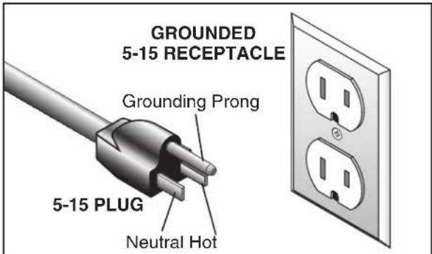
For 110V operation: This machine is equippe with a power cord that has an equipment-grounding wire and a grounding plug (see following figure). The plug must only be inserted into a matching receptacle (outlet) that is properly installed and grounded in accordance with all local codes and ordinances.
text_image
GROUNDED 5-15 RECEPTACLE Grounding Prong 5-15 PLUG Neutral HotFigure 2. Typical 5-15 plug and receptacle.
CAUTION
natural_image
Three circular icons showing different types of electrical plugs and a wall socket, all without any text or symbols.SHOCK HAZARD!
Two-prong outlets do not meet the grounding requirements for this machine. Do not modify or use an adapter on the plug provided—if it will not fit the outlet, have a qualified electrician install the proper outlet with a verified ground.
For 220V operation: The plug specified under "Circuit Requirements for 220V" on the previous page has a grounding prong that must be attached to the equipment-grounding wire on the included power cord. The plug must only be inserted into a matching receptacle (see following figure) that is properly installed and grounded in accordance with all local codes and ordinances.

text_image
GROUNDED 6-15 RECEPTACLE Current Carrying Prongs 6-15 PLUG Grounding ProngFigure 3. Typical 6-15 plug and receptacle.
Extension Cords
We do not recommend using an extension co with this machine. If you must use an extension cord, only use it if absolutely necessary and only on a temporary basis.
Extension cords cause voltage drop, which ca damage electrical components and shorten motor life. Voltage drop increases as the extension cord size gets longer and the gauge size gets smaller (higher gauge numbers indicate smaller sizes).
Any extension cord used with this machine must be in good condition and contain a ground w and matching plug/receptacle. Additionally, it mus meet the following size requirements:
Minimum Gauge Size ....14 AWG Maximum Length (Shorter is Better).....50 ft.
Voltage Conversion
The voltage conversion MUST be performed by a electrician or qualified service personnel. To perform the voltage conversion, install the correct plug and rewire the motor to the new voltage, according to the provided wiring diagram on Page 56.
Note: If the diagram included on the motor conflicts with the one in this manual, the motor may have changed since the manual was printed. Use the diagram provided inside the motor wiring junction box.
To convert the machine to 220V:
- DISCONNECT MACHINE FROM POWER!
- Replace the 5-15 plug on the power cord with a 6-15 plug.
- Re-wire the motor as illustrated in the wiring diagram.
text_image
Illustration of a hand interacting with an open book displaying technical diagrams and text blocks, likely illustrating a scientific or educational concept.WARNING
This machine presents serious injury hazards to untrained users. Read through this entire manual to become familiar with the controls and operations before starting the machine!

natural_image
Illustration of a pair of eyeglasses with black frames and reflective lenses (no text or symbols)WARNING
Wear safety glasses during the entire setup process!

natural_image
Silhouette of two figures sitting at a table, no text or symbols presentWARNING
This machine and its components are very heavy. Get lifting help or use power lifting equipment such as a forklift to move heavy items.
Needed for Setup
The following are needed to complete the setup process, but are not included with your machine.
Description
Qty
- Safety Glasses ....1
- Cleaner/Degreaser ......As Needed
- Disposable Shop Rags ......As Needed
• Additional People for Lifting ...... At Least 1 - Level 1
• Hex Wrench 5mm ....1 - Wrench or Socket 10mm ......2
- Wrench or Socket 13mm ......2
- Dust Collection System ....1
- Dust Hose 4" ....1
- Hose Clamps 4" ....2
Unpacking
Your machine was carefully packaged for safe transportation. Remove the packaging materials from around your machine and inspect it. If you discover the machine is damaged, please immediately call us at (570) 546-9663 for advice.
Save the containers and all packing materials for possible inspection by the carrier or its agent. Otherwise, filing a freight claim can be difficult.
When you are completely satisfied with the condition of your shipment, inventory the contents.
natural_image
Simple line drawing of a trash can with a paper stack and recycling symbol (no text or labels)WARNING
SUFFOCATION HAZARD!
Keep children and pets away from plastic bags or packing materials shipped with this machine. Discard immediately.
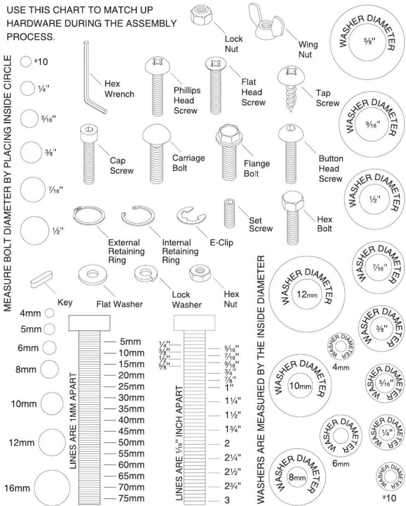
Hardware Recognition Chart
other
| Component | Inner Diameter (mm) | |-----------|---------------------| | Lines ARE 1MM APART | 5mm | | 4mm | 5mm | | 6mm | 6mm | | 8mm | 8mm | | 10mm | 10mm | | 12mm | 12mm | | 16mm | 16mm | | Key | Flat Washer | | Cap Screw | External Retaining Ring | | Carriage Bolt | Internal Retaining Ring | | Flange Bolt | E-Clip | | Set Screw | Hex Bolt | | Lock Washer | Hex Nut | | Phillips Head Screw | 1/4"–1/6" INCH APART | | Wing Nut | 5/16"–7/16" INCH APART | | Tap Screw | 7/16"–9/16" INCH APART | | Lock Nut | 1/4"–2/4" INCH APART | | Lock Washer | 1/4"–2/4" INCH APART | | Lock Washer | 2/4"–2/4" INCH APART | | Lock Washer | 3/4"–2/4" INCH APART | | Lock Washer | 3/4"–2/4" INCH APART | | Lock Washer | 5/4"–2/4" INCH APART | | Lock Washer | 5/8"–2/4" INCH APART | | Lock Washer | 5/8"–2/4" INCH APART | | Lock Washer | 7/8"–2/4" INCH APART | | Lock Washer | 7/8"–2/4" INCH APART | | Lock Washer | 9/8"–2/4" INCH APART | | Lock Washer | 9/8"–2/4" INCH APART | | Lock Washer | 10mm–12mm (inner circle) | | Lock Washer | 10mm–12mm (outer circle) | | Lock Washer | 12mm–16mm (inner circle) | | Lock Washer | 16mm–16mm (outer circle) | | Lock Washer | 2mm–2/4" (inner circle) | | Lock Washer | 2/4"–2/4" (outer circle) | | Lock Washer | 2/4"–2/4" (inner circle) | | Lock Washer | 3m–3/4" (inner circle) | | Lock Washer | 3m–3/4" (outer circle) | | Lock Washer | 3m–3/4" (inner circle) | | Lock Washer | 3m–3/4" (outer circle) | | Lock Washer | 3m–3/4" (inner circle) | | Lock Washer | 3m–3/4" (outer circle) | | Lock Washer | 3m–3/4" (inner circle) | | Lock Washer | 3m–3/4” (outer circle) | | Lock Washer | 3m–3/4” (inner circle) | | Lock Washer | 3m–3/4” (outer circle) | | Lock Washer | 3m–3/4” (inner circle) | | Lock Washer | 3m–3/4” (outer circle) | | Lock Washer | 3m–3/4” (inner circle) | | Lock Washer | 3m–3/4” (outer circle) | | Lock Washer | 3m–3 /4" (inner circle) | | Lock Washer | 3m–3 /4" (outer circle) | | Lock Washer | 3m–3 /4" (inner circle) | | Lock Washer | 3m–3 /4" (outer circle) | | Lock Washer | 3m–3 /4" (inner circle) | | Lock Washer | 3m–3 /4" (outer circle) | | Lock Washer | 3m–3 /4" (inner circle) | | Lock Washer | 3m–3/4" (inner circle) | | Lock Washer | 3m–3 /4" (inner circle) | | Lock Washer | 3m–3 /4" (inner circle) | | Lock Washer | 3m–3 /4" (inner circle) | | Lock Washer | 3m–3 /4" (inner circle) | | Lock Washer | 3m–3 /4" (inner circle) | | Lock Washer | 3m–3 /4" (inner circle) | | Lock Washer | 3m-3 /4" (inner circle) | | Lock Washer | 3m-3 /4" (outer circle) | | Lock Washer | 3m-3 /4" (inner circle) | | Lock Washer | 3m-3 /4" (outer circle) | | Lock Washer | 3m-3 /4" (inner circle) | | Lock Washer | 3m-3 /4" (outer circle) | | Lock Washer | 3m-3 /4" (inner circle) | | Lock Washer | 3m-3 /4” (inner circle) | | Lock Washer | 3m-3 /4” (outer circle) | | Lock Washer | 3m-3 /4” (inner circle) | | Lock Washer | 3m-3 /4” (outer circle) | | Lock Washer | 3m-3 /4” (inner circle) | | Lock Washer | 3m-3 /4” (outer circle) | | Lock Washer | 3m-3 /4” (inner circle) | | Lock Washer | 3m-3 /4" (outer circle) | | Lock Washer | 3m-3 /4” (inner circle) | | Lock Washer | 3m-3 /4” (outer circle) | | Lock Washer | 3m-3 /4” (inner circle) | | Lock Washer | 3m-3 /4” (outer circle) | | Lock Washer | 3m-3 /4” (inner circle) | | Lock Washer | 3m-3/4” (inner circle) | | Lock Washer | 3m-3 /4” (outer circle) | | Lock Washer | 3m-3 /4” (inner circle) | | Lock Washer | 3m-3 /4” (outer circle) | | Lock Washer | 3m-3 /4” (inner circle) | | Lock Washer | 3m-3 /4” (outer circle) | | Lock Washer | 3m -5/8" (inner circle) | | Lock Washer | 5/8" (outer circle) | | Washer Diameter: #10, #10' (inner circle) and #10' (outer circle)Inventory
The following is a list of items shipped with your machine. Before beginning setup, lay these items out and inventory them.
If any non-proprietary parts are missing (e.g. nut or a washer), we will gladly replace them; or for the sake of expediency, replacements can be obtained at your local hardware store.
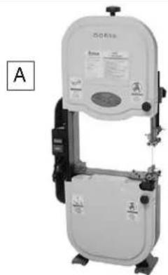
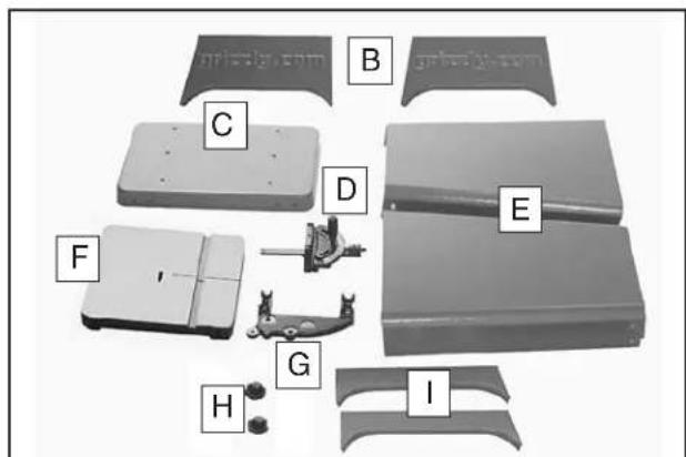
Shipping Inventory: (Figures 4–6) Qty
A. Bandsaw Assembly....1
B. Upper Stand Braces....2
C. Stand Top....1
D. Miter Gauge Assembly .....1
E. Stand Sides....2
F. Table w/Insert & Table Pin ....1
G. Table Trunnion....1
H. Table Lock Knobs 38 "-16.....2
I. Lower Stand Braces .....2
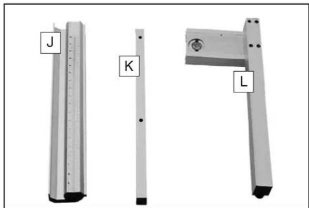
J. Front Fence Rail ....1
K. Rear Fence Rail ....1
L. Fence Assembly....1
M. Hardware (Not Shown):
—Hex Bolts M6-1 x 16 (Stand).... 16
—Flat Washers 6mm (Stand).... 16
—Flange Nuts M6-1 (Stand) 16
—Stand Feet 38 "-16 x 2" (Stand) ..... 4
—Hex Nuts 3/8 -16 (Stand Feet).... 8
—Flat Washers 38 " (Stand Feet) ..... 8
—Carriage Bolts M8-1.25 x 16 (Stand) ..... 8
—Flange Nuts M8-1.25 (Stand)....8
—Hex Bolts M8-1.25 x 35 (Bandsaw) ..... 4
—Flat Washers 8mm (Bandsaw) ...... 8
—Lock Washers 8mm (Bandsaw) ..... 4
—Hex Nuts M8-1.25 (Bandsaw) 4
—Hex Bolts M8-1.25 x 30 (Trunnion) ..... 2
—Lock Washers 8mm (Trunnion)....2
—Hex Bolt M8-1.25 x 80 (Positive Stop) .... 1
—Hex Nut M8-1.25 (Positive Stop).... 1
—Fence Stand-Off M6-1 x 20 (Fence) ..... 1
—Lock Handle M8-1.25 x 20 (Fence)...... 1
—Cap Screws M6-1 x 16 Black (Fence) .... 2
—Hex Bolts M6-1 x 20 Black (Fence) ..... 2
—Lock Washers 6mm Black (Fence) ..... 2
—Flat Washers 6mm Black (Fence) ...... 2
—Hex Nut M8-1.25 Black (Fence).... 1
—Hex Nut M6-1 Black (Fence).... 1
natural_image
Exterior view of a medical or laboratory device with no visible text or symbols on the device itself.Figure 4. Bandsaw assembly.
text_image
B C D E F G H IFigure 5. Other components.
text_image
J K LFigure 6. Fence components.
NOTICE
If you cannot find an item on this list, carefully check around/inside the machine and packaging materials. Often, these items get lost in packaging materials while unpacking or they are pre-installed at the factory.
Cleanup
The unpainted surfaces of your machine are coated with a heavy-duty rust preventative that prevents corrosion during shipment and storage. This rust preventative works extremely well, but it will take a little time to clean.
Be patient and do a thorough job cleaning your machine. The time you spend doing this now will give you a better appreciation for the proper care of your machine's unpainted surfaces.
There are many ways to remove this rust preventative, but the following steps work well in a wide variety of situations. Always follow the manufacturer's instructions with any cleaning product you use and make sure you work in a well-ventilated area to minimize exposure to toxic fumes.
Before cleaning, gather the following:
- Disposable rags
- Cleaner/degreaser (WD•40 works well)
• Safety glasses & disposable gloves - Plastic paint scraper (optional)
Basic steps for removing rust preventative:
- Put on safety glasses.
- Coat the rust preventative with a liberal amount of cleaner/ degreaser, then let it soak for 5–10 minutes.
- Wipe off the surfaces. If your cleaner/degreaser is effective, the rust preventative will wipe off easily. If you have a plastic paint scraper, scrape off as much as you can first, then wipe off the rest with the rag.
- Repeat Steps 2–3 as necessary until clean, then coat all unpainted surfaces with a quality metal protectant to prevent rust.

text_image
GASWARNING
Gasoline and petroleum products have low flash points and can explode or cause fire if used to clean machinery. Avoid using these products to clean machinery.

natural_image
Illustration of a cartoon rabbit holding a propeller above a box (no text or symbols)CAUTION
Many cleaning solvents are toxic if inhaled. Only work in a well-ventilated area.
NOTICE
Avoid chlorine-based solvents, such as acetone or brake parts cleaner, that may damage painted surfaces.
Weight Load
Refer to the Machine Data Sheet for the weight of your machine. Make sure that the surface upon which the machine is placed will bear the weight of the machine, additional equipment that may be installed on the machine, and the heaviest workpiece that will be used. Additionally, consider the weight of the operator and any dynamic loading hat may occur when operating the machine.
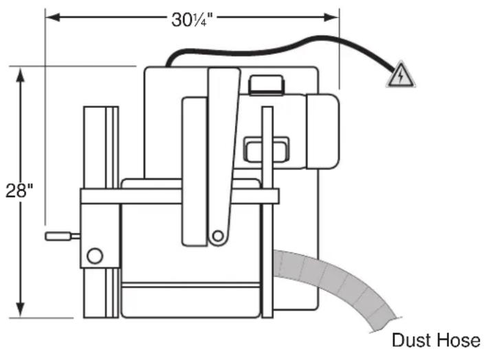
Space Allocation
Consider the largest size of workpiece that will be processed through this machine and provide enough space around the machine for adequate operator material handling or the installation of auxiliary equipment. With permanent installations, save enough space around the machine to open or remove doors/covers as required by the maintenance and service described in this manual. See below for required space allocation.

CAUTION
Children or untrained people may be seriously injured by this machine. Only install in an access restricted location.
Physical Environment
The physical environment where the machine operated is important for safe operation and longevity of machine components. For best resu operate this machine in a dry environment that free from excessive moisture, hazardous chemicals, airborne abrasives, or extreme condition. Extreme conditions for this type of machinery a generally those where the ambient temperat range exceeds 41^-104^ ; the relative humid range exceeds 20%–95% (non-condensing); the environment is subject to vibration, shock or bumps.
Electrical Installation
Place this machine near an existing power sour Make sure all power cords are protected from traffic, material handling, moisture, chemicals, other hazards. Make sure to leave enough space around machine to disconnect power supply apply a lockout/tagout device, if required.
Lighting
Lighting around the machine must be adequate enough that operations can be performed safe. Shadows, glare, or strobe effects that may distr or impede the operator must be eliminated.
text_image
30¼" 28" Dust HoseFigure 7. Minimum working clearances.
Assembly
text_image
CAUTION Some metal parts may have sharp edges that can cause minor injury. Please examine the edges of all metal parts BEFORE handling them and be careful WHILE handling them.To assemble the bandsaw:
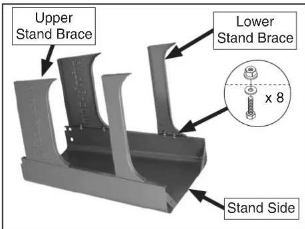
- Lay one stand side flat on a protective surface, then attach the upper and lower stand braces, as shown in Figure 8, with (8) M6-1 x 16 hex bolts, (8) 6mm flat washers, and (8) M6-1 flange nuts.
Note: Only hand-tighten the stand fasteners for now during these initial steps. Once the stand is fully assembled you will be instructed to fully tighten all fasteners.
text_image
Upper Stand Brace Lower Stand Brace x 8 Stand SideFigure 8. Upper and lower stand braces attached to the stand side.
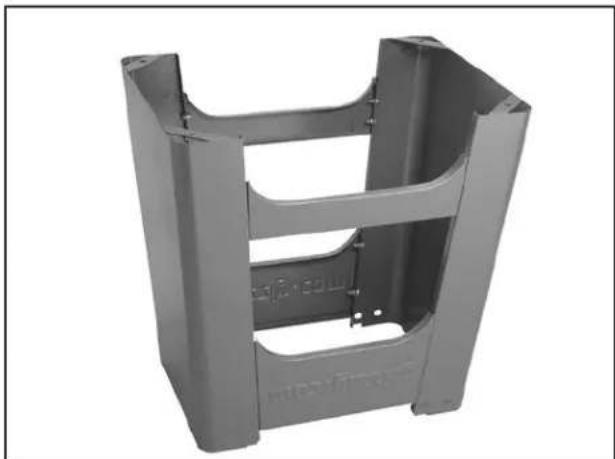
- Attach the remaining stand side to the assembly, as shown in Figure 9, with (8) M6-1 x 16 hex bolts, (8) 6mm flat washers, and (8) M6-1 flange nuts.
natural_image
Metallic mechanical bracket component with U-shaped cutouts and mounting holes (no text or symbols visible)Figure 9. Second stand side attached.
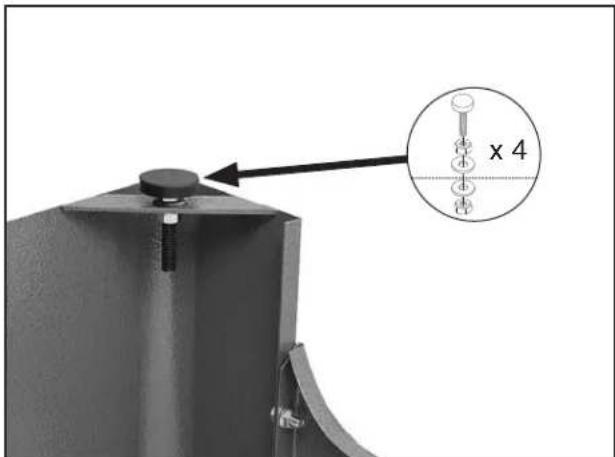
- Install the foot assemblies into the holes in the bottom of the stand assembly, using (2) ^3/8 "-16 hex nuts and (2) 10mm flat washers, as shown in Figure 10.
Note: Adjust the feet so that they are approximately the same height—this will make leveling the stand easier in a later step.
text_image
x 4Figure 10. Stand foot installed (1 of 4).
- Turn the stand assembly upright and attach the top, as shown in Figure 11, with (8) M8-1.25 x 16 carriage bolts and (8) M8-1.25 flange nuts.
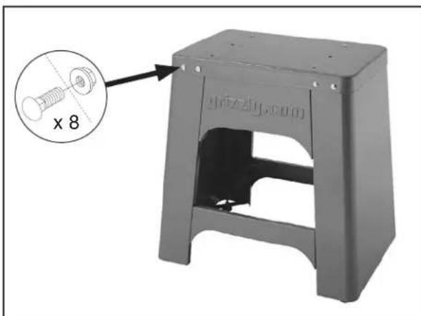
natural_image
Metal stool with a magnified inset showing a bolt and screw (no text or symbols on the object itself)Figure 11. Stand top attached.
- Square up the stand components and fully tighten all the fasteners.
- Place the level on top of the stand assembly, as shown in Figure 12, then adjust the feet up or down to make the stand top level from side to side and front to back. Make sure that both hex nuts on the feet are tight against the stand assembly.
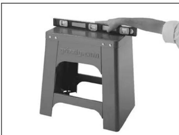
natural_image
Hand placing a black plastic stool into a gray metal frame (no text or symbols visible)Figure 12. Leveling the stand.
- With the help of other people, lift the bandsaw assembly onto the stand and align the mounting holes.
- Secure the bandsaw assembly to the stand with (4) M8-1.25 x 35 hex bolts, (8) 8mm flat washers, (4) 8mm lock washers, and (4) M8-1.25 hex nuts, as shown in Figure 13.
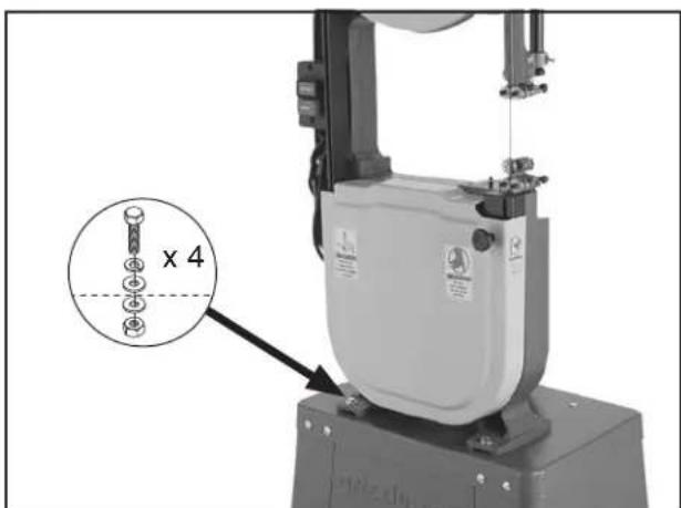
text_image
x 4Figure 13. Bandsaw assembly attached to the stand.
- Position the table trunnion on the bandsaw, as shown in Figure 14, then secure it with the (2) M8-1.25 x 30 hex bolts and (2) 8mm lock washers.
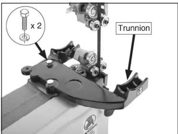
text_image
x 2 TrunnionFigure 14. Trunnion installed.
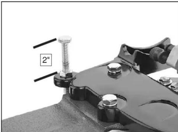
- Thread the remaining M8-1.25 hex nut onto the M8-1.25 x 80 positive stop hex bolt, then thread the bolt into the trunnion so that approximately 2" protrudes above the trunnion (see Figure 15). This will allow the table to rest approximately level when it is installed during the following steps.
natural_image
Close-up of a mechanical clamp or bracket with bolts and a 2-inch bolt, no visible text or symbolsFigure 15. Positive stop installed.
- Remove the aluminum table insert from the center of the table and remove the table pin from the end of the table slot (see Figure 16).

text_image
Insert PinFigure 16. Table insert and pin.
-
Line up the blade with the table slot and move the table around the blade until the blade is in the center of the table, then turn the table 90° counterclockwise and rest it on the trunnions so that the bolts protrude from the bottom of the trunnions.
-
Secure the table by threading the (2) _8 "-16 table lock knobs onto the bolts, as shown in Figure 17.
text_image
WARNING DO NOT OPEN WHILEFigure 17. Securing table to the trunnion.
- Replace the table insert and pin removed in Step 11. Make sure the table insert sits flush with the table surface.
Continued on next page →
- Attach the front fence rail to the table with the (2) M6-1 x 20 hex bolts, (2) 6mm lock washers, and (2) 6mm flat washers (see Figure 18).
Note: There is a small amount of vertical play in the rail holes. Make sure to position the rail evenly along its length before tightening the hex bolts. This will allow the fence to ride across the table with the proper amount of clearance.
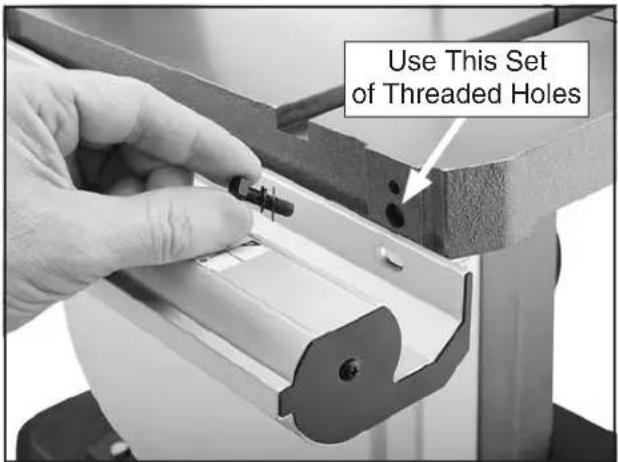
text_image
Use This Set of Threaded HolesFigure 18. Attaching the front fence rail.
- Attach the rear fence rail to the table with the (2) black M6-1 x 16 cap screws (see Figure 19).
natural_image
Close-up of hands operating a machine tool with a saw, no visible text or symbolsFigure 19. Attaching the rear fence rail.
-
Thread (1) M8-1.25 hex nut onto the fence lock handle, then thread the handle into the fence and secure it in place by tightening the hex nut against the fence.
-
Move the fence lock handle up, position the fence face between the column and the blade, as shown in Figure 20, then place it onto the front fence rail.
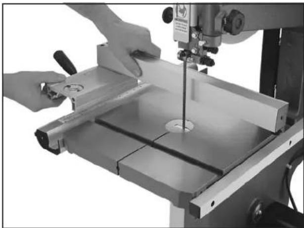
natural_image
Close-up of hands operating a machine tool with a metal plate and cutting tool (no visible text or symbols)Figure 20. Placing the fence onto the rails.
- Thread the M6-1 hex nut onto the fence stand-off, then thread it into the rear underside of the fence (see Figure 21) so that the fence rests the same height above the table along its full length. Tighten the hex nut against the fence to secure the setting.
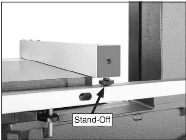
text_image
Stand-OffFigure 21. Fence stand-off installed.
Blade Center Tracking
Blade tracking is affected by the tilt of the upper wheel (known as center tracking) and the alignment of both wheels (known as coplanar tracking).
The wheels on this bandsaw were aligned at the factory, so center tracking is the only adjustment that needs to be performed when the saw is new (refer to the Wheel Alignment on Page 49 for detailed instructions on coplanar tracking).
Note: Changes in the blade tension may change the blade tracking. For best performance, regularly check and maintain the proper blade tracking.
To center track the blade:
-
DISCONNECT BANDSAW FROM POWER!
-
Adjust the upper and lower blade guides away from the blade (refer to Adjusting Blade Guide Bearings later in this manual for detailed instructions).
Note: When adjusting the blade tracking, the blade must have a reasonable amount of tension to simulate operating conditions. After the Test Run is successfully completed, you will perform a thorough version of the following steps to correctly tension the blade.
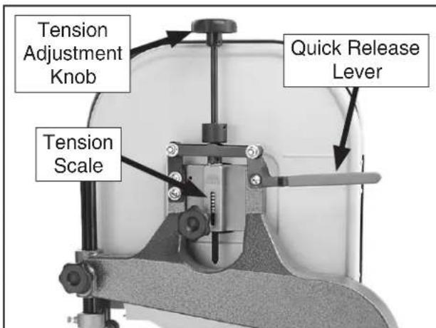
- Move the quick release lever up to the vertical position (see the following figure), then use the blade tension adjustment knob to bring the red marker to the correct mark on the tension scale for the blade installed.
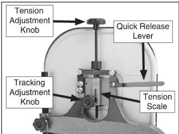
text_image
Tension Adjustment Knob Quick Release Lever Tracking Adjustment Knob Tension ScaleFigure 22. Blade tension and center tracking controls.
-
To tension the blade, pull the tension quick release lever down to the horizontal position.
-
Open the upper wheel cover, then spin the upper wheel by hand at least three times and watch how the blade rides on the crown of the wheel. Refer to the figure below for an illustration of this concept.
—If the blade rides on the center of the crown, then the bandsaw is already tracked properly and no additional adjustments are needed. Skip to Step 9.
—If the blade does not ride on the center of the crown, then continue with the next step.
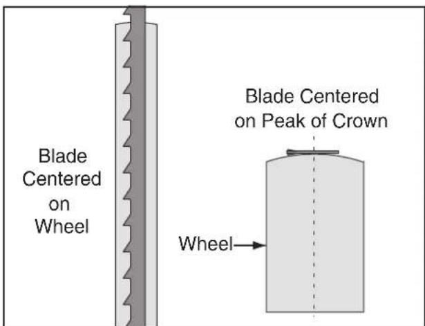
text_image
Blade Centered on Wheel Blade Centered on Peak of Crown WheelFigure 23. Profiles of blade properly center tracking.
- Unlock the blade tracking adjustment knob so the knob will rotate for adjustments in the next steps.
Note: The blade tracking adjustment knob controls the tilt of the upper wheel which, in turn, controls the center tracking of the blade.
- Spin the upper wheel with one hand and use the blade tracking adjustment knob with the other hand to make the blade ride in the center of the bandsaw wheel tire.
- After the blade consistently rides in the center of the wheel after several rotations, lock the blade tracking adjustment knob to secure the setting.
- Close the upper wheel cover.
Note: For the best performance from your saw, regularly maintain the proper tracking of the blade.
Dust Collection
CAUTION
DO NOT operate this bandsaw without an adequate dust collection system. This bandsaw creates substantial amounts of wood dust while operating. Failure to use a dust collection system can result in short and long-term respiratory illness.
Recommended CFM at Dust Port: 400 CFM Do not confuse this CFM recommendation with the rating of the dust collector. To determine the CFM at the dust port, you must consider these variables: (1) CFM rating of the dust collector, (2) hose type and length between the dust collector and the machine, (3) number of branches or wyes, and (4) amount of other open lines throughout the system. Explaining how to calculate these variables is beyond the scope of this manual. Consult an expert or purchase a good dust collection "how-to" book.
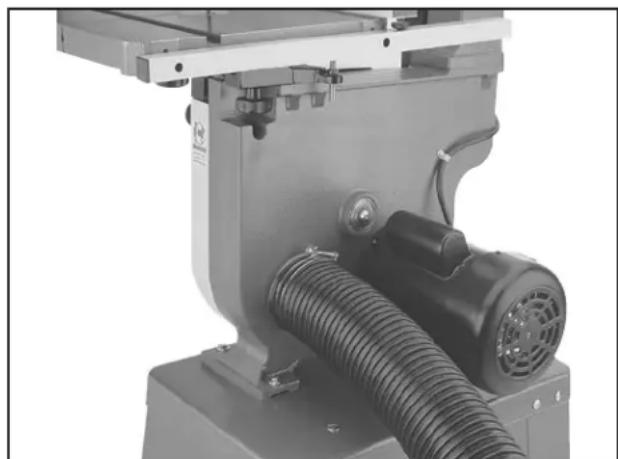
To connect a dust collection hose:
- Fit the dust hose over the dust port, as shown in the figure below, and secure in place with a hose clamp.
- Tug the hose to make sure it does not come off.
Note: A tight fit is necessary for proper performance.
natural_image
Industrial machine component with coiled tubing and mounting bracket (no visible text or symbols)Figure 24. 4" dust hose attached to dust port.
Power Connection
After you have completed all previous setup instructions and circuit requirements, the machine is ready to be connected to the power supply.
To avoid unexpected startups or property damage, use the following steps whenever connecting or disconnecting the machine.
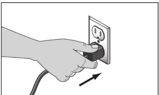
Connecting Power
- Turn the machine power switch OFF.
- Insert the power cord plug into a matching power supply receptacle. The machine is now connected to the power source.
natural_image
Hand inserting a plug into an electrical outlet, showing power and current direction (no text or symbols)Figure 25. Connecting power.
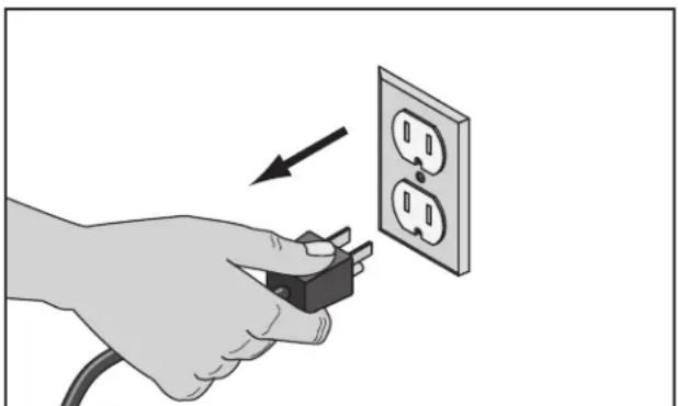
Disconnecting Power
- Turn the machine power switch OFF.
- Grasp the molded plug and pull it completely out of the receptacle. Do not pull by the cord as this may damage the wires inside.
natural_image
Hand holding a plug inserted into an electrical outlet, with an arrow indicating the direction (no text or symbols present)Figure 26. Disconnecting power.
Test Run
Once the assembly is complete, test run your machine to make sure it runs properly and is ready for regular operation.
The test run consists of verifying the following: 1) The motor powers up and runs correctly, and 2) the safety disabling mechanism on the switch works correctly.
If, during the test run, you cannot easily locate the source of an unusual noise or vibration, stop using the machine immediately, then review Troubleshooting on Page 45.
If you still cannot remedy a problem, contact our Tech Support at (570) 546-9663 for assistance.
To test run the machine:
- Make sure you have read the safety instructions at the beginning of the manual and that the machine is set up properly.
- Make sure all tools and objects used during setup are cleared away from the machine.
- Verify that the machine is operating correctly by turning it ON.
—When operating correctly, the machine runs smoothly with little or no vibration or rubbing noises.
—Investigate and correct strange or unusual noises or vibrations before operating the machine further. Always disconnect the machine from power when investigating or correcting potential problems.
Continued on next page →
-
Turn the machine OFF.
-
Insert a switch disabling padlock (sold separately) through the green ON button, as shown in Figure 27.
text_image
Shaft ON OFF PadlockFigure 27. Switch disabling padlock inserted into ON button.
- Press the green ON button to test the disabling feature on the switch.
—If the machine does not start, the switch disabling feature is working as designed.
—If the machine starts, immediately stop it. The switch disabling feature is not working correctly. This safety feature must work properly before proceeding with regular operations. Call Tech Support for help.
Tensioning Blade
A properly tensioned blade is essential for making accurate cuts, extending the life of the blade, and making many other bandsaw adjustments.
Note: Before you performed the Test Run, you tensioned the blade according to the blade tension scale, which is only an approximate tension. The following procedure fine tunes the blade tension to ensure more accurate cutting results.
To tension the bandsaw blade:
-
Make sure the blade is properly center tracking as instructed in the Blade Tracking subsection previous to the Test Run.
-
To tension the blade, pull the tension quick release lever down to the horizontal position.
text_image
Tension Adjustment Knob Tension Scale Quick Release LeverFigure 28. Blade tension controls.
-
Turn the bandsaw ON.
-
Slowly rotate the blade tension adjustment knob counterclockwise one quarter of a turn at a time—this will release blade tension. When you see the blade start to flutter, stop decreasing tension.
Now, slowly rotate the knob clockwise to increase the tension until the blade stops fluttering, then tighten the blade tension adjustment knob one more quarter of a turn.
- Look at what the tension gauge reads and use that as a guide for tensioning that blade in the future.
Note: Do not rely on this setting for long periods of time because the blade will stretch with use.
Additionally, with extended use, the blade tensioning system may need to be reset for correct operation. Refer to the Resetting Blade Tensioner in the Service section on this manual.
NOTICE
When using a 34 " blade, the blade tensioning system may need to be reset for correct operation. Refer to Blade Tensioner on Page 53 for detailed instructions.
Adjusting Blade Support Bearings
The support bearings are positioned behind the blade to prevent it from deflecting backward during cutting operations. Proper adjustment of the support bearings is an important part of making accurate cuts and keeps the blade teeth from coming in contact with the blade guides while cutting.
There are support bearings on the upper and lower blade guide assemblies. Both adjust in the same manner.
NOTICE
Whenever changing a blade or adjusting tension and tracking, the upper and lower support bearings and blade guides must be re-adjusted before cutting operations.
Tool Needed Qty
Wrench 10mm ....1
To adjust the support bearings:
- Make sure the blade is tracking properly and is correctly tensioned.
- DISCONNECT BANDSAW FROM POWER!
- Familiarize yourself with the support bearing controls shown in the figure below.
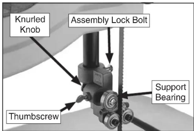
text_image
Knurled Knob Assembly Lock Bolt Support Bearing ThumbscrewFigure 29. Support bearing controls.
- Loosen the guide assembly lock bolt so that the support bearing can be rotated perpendicular to the blade in the next step.
- Rotate the blade guide assembly until the face of the support bearing is perpendicular to the blade, as illustrated in the figure below.
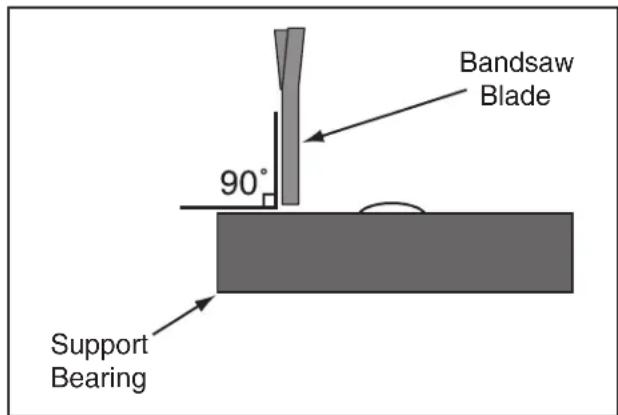
text_image
Bandsaw Blade 90° Support BearingFigure 30. The face of the support bearing must be perpendicular (90°) to the blade.
- Tighten the guide assembly lock bolt to secure the setting.
- Loosen the thumbscrew on the support bearing adjustment shaft.
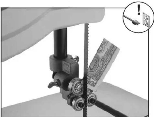
- Use the knurled knob to position the support bearing approximately 0.016" behind the blade, as illustrated in the figure below.
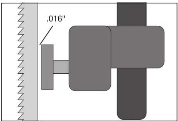
text_image
.016"Figure 31. The face of the support blade must be approximately 0.016" behind the blade.
Tip: To quickly gauge this setting, fold a crisp dollar bill in half twice (when folded tightly, four thicknesses of a dollar bill is approximately 0.016"). Place the folded dollar bill between the support bearing and the blade, as shown in the figure below.
natural_image
Close-up of a hand using a mechanical tool to cut a piece of money, with an inset showing a fuse and warning symbol (no readable text)Figure 32. Dollar bill folded twice to make a quick 0.016" gauge.
- Tighten the thumbscrew to lock the support bearing in place.
Adjusting Blade Guide Bearings
Properly adjusting the blade guides provides side-to-side support to help keep the blade straight while cutting, which is essential to making accurate cuts.
Tool Needed Qty
Hex Wrench 4mm 2
To adjust the upper and lower blade guides:
- Make sure that the blade is tracking properly and is correctly tensioned.
- DISCONNECT BANDSAW FROM POWER!
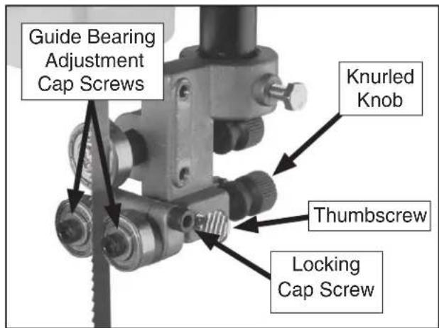
- Familiarize yourself with the blade guide controls shown in the figure below.
text_image
Guide Bearing Adjustment Cap Screws Knurled Knob Thumbscrew Locking Cap ScrewFigure 33. Blade guide bearing controls.
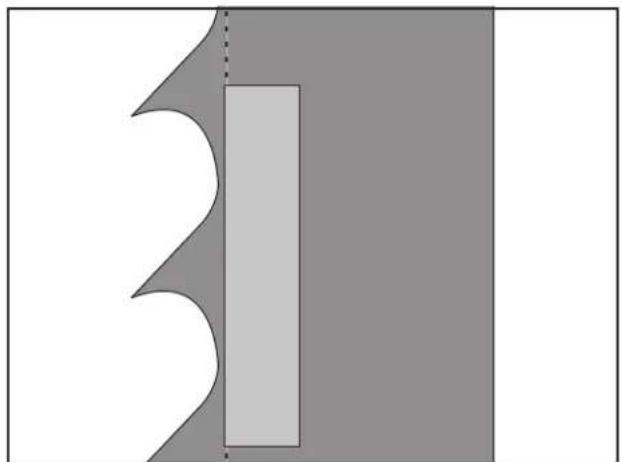
- Loosen the thumbscrew shown in the figure above, then use the knurled knob to adjust the guide bearings laterally so that the bearing faces are just behind the blade gullet, as illustrated in the following figure.
natural_image
Abstract geometric shape with a vertical rectangle and angular cutouts, no text or symbols presentFigure 34. The blade guide bearings should be positioned just behind the blade gullets.
Note: With wider blades, it may not be possible to bring the guide bearings just behind the blade gullets. In that case, position them as far forward as possible without allowing the guide bearing housing to touch the back of the blade.
NOTICE
To reduce the risk of damage to the blade or guide bearings, make sure that the bearings do not contact the blade teeth when the blade is deflected backward.
-
When you are satisfied with the lateral adjustment of the guide bearings, re-tighten the thumbscrew to secure the setting.
-
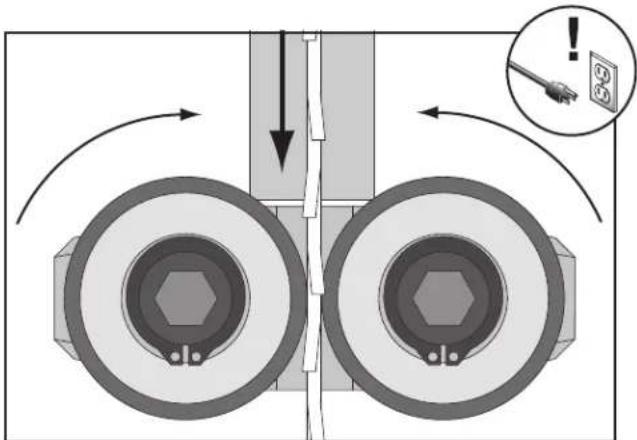
Loosen both cap screws behind the guide bearings, then rotate the adjustment cap screws so the bearings evenly and lightly touch the sides of the blade (see the illustration in the following figure).
Note: When the blade guide bearings are properly adjusted against the blade, they should still be able to rotate.
text_image
Diagram illustrating mechanical assembly with labeled components and directional arrows, including a warning icon and electrical socket symbol.Figure 35. Blade guide bearings evenly and lightly touching the sides of the blade.
- While keeping the adjustment cap screws from turning with one hex wrench, re-tighten the locking cap screws to secure the settings.
NOTICE
Whenever changing a blade or adjusting the blade tension or tracking, the support and guide bearings must be re-adjusted before resuming operation.
Table Tilt Calibration
When properly adjusted, the positive stop bolt enables the table to be quickly returned perpendicular with the blade.
To tilt the table to the left, the positive stop bolt must be lowered from its correct height, then re-adjusted after the table is returned to 0^ .
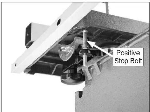
text_image
Positive Stop BoltFigure 36. Positive stop bolt set at 90° (viewed from behind the table).
Tools Needed Qty
Wrench 13mm....1
Phillips Screwdriver #2 ....1
Machinist's Square ....1
To set the positive stop 90° to the blade:
- Make sure the blade is correctly tensioned as described in the Tensioning Blade subsection earlier in this manual.
- DISCONNECT BANDSAW FROM POWER!
- Loosen the two table lock knobs that secure the table to the trunnions.
-
Loosen the hex nut that locks the positive stop bolt in place.
-
Completely raise the upper blade guide assembly, then place the machinist's square flat on the table and against the side of the blade, as illustrated in the figure below.
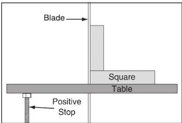
text_image
Blade Square Table Positive StopFigure 37. Using a square to adjust the table perpendicular to the side of the blade.
- Raise or lower the positive stop bolt until the table is perpendicular to the side of the blade, then re-tighten the hex nut against the casting to secure the setting.
- Rest the table on the positive stop bolt, then re-tighten the table lock knobs to secure the table perpendicular to the side of the blade.
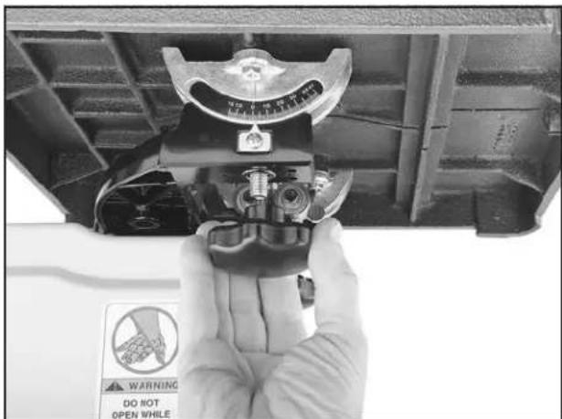
- Observe the position of the table tilt pointer on the tilt scale located underneath the front of the table (see the figure below).
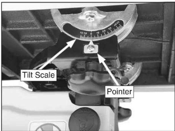
text_image
Tilt Scale PointerFigure 38. Location of the table tilt scale.
- If the pointer is not correctly positioned at the 0^ mark, then loosen the pointer screw, position the pointer at the 0^ mark, and re-tighten the screw to hold it in place.
Aligning Table
To ensure cutting accuracy when the table is first installed, the table should be aligned so the miter slot is parallel to the bandsaw blade.
Tools Needed Qty
Straightedge 2'....1
Fine Ruler ....1
Masking Tape ......As Needed
Wrench 10mm....1
To align the table to the blade:
-
Make sure the blade is correctly tensioned as described in the Tensioning Blade subsection earlier in this manual.
-
DISCONNECT BANDSAW FROM POWER!
-
Make sure the table is perpendicular to the side of the blade and locked in place.
-
Place an accurate straightedge along the blade. The straightedge should lightly touch both the front and back of the blade (see Figure 39).
Note: Make sure the straightedge does not go across a tooth.
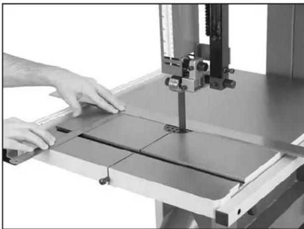
natural_image
Person operating a 3D printer on a workbench with metal sheets (no visible text or symbols)Figure 39. Measuring for table-to-blade parallelism.
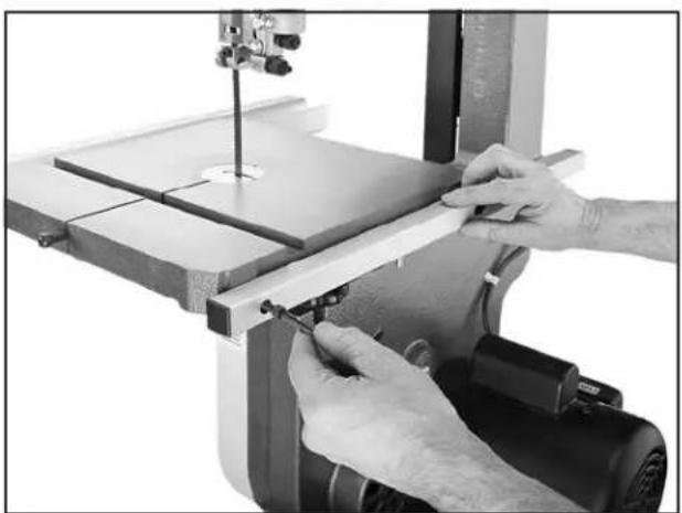
- Use the fine ruler to measure the distance from the straightedge and the miter slot along the full depth of the table.
—If the distances are the same, no further adjustments are required.
—If the distances are different, continue with Step 6.
- Loosen the six flange bolts that secure the table to the trunnion brackets (see the figure below).

text_image
Flange Bolts (3 of 6)Figure 40. Location of trunnion bracket flange bolts.
-
Shift the table so that the distances are equal between the straightedge and miter slot along the full depth of the table.
-
Taking care not to move the table further, re-tighten the flange bolts.
-
Verify the setting and, if necessary, repeat this procedure until you are satisfied with the adjustment.
Aligning Fence
To ensure accurate cutting when using the fence, the face of the fence must be parallel to the table miter slot and, thus, to the side of the blade.
Tools Needed Qty
Hex Wrench 5mm ....1
To align the fence parallel with the miter slot:
-
Make sure the miter slot is parallel with the blade, as instructed in the previous Aligning Table procedure.
-
DISCONNECT BANDSAW FROM POWER!
-
Install the fence on the right side of the blade, even with the edge of the miter slot, then lock it in place.
— If the fence is parallel with the miter slot, no adjustment is necessary.
— If the fence is not parallel with the miter slot, proceed to Step 4.
- Loosen the four fence adjustment cap screws shown in the figure below, adjust the fence parallel to the miter slot, then re-tighten the cap screws to secure the setting.
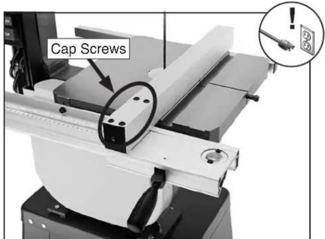
text_image
Cap ScrewsFigure 41. Location of the fence adjustment cap screws.
SECTION 4: OPERATIONS
Operation Overview
The purpose of this overview is to provide the novice ice machine operator with a basic understanding of how the machine is used during operation, so the machine controls/components discussed later in this manual are easier to understand.
Due to the generic nature of this overview, it not intended to be an instructional guide. To learn more about specific operations, read this entire manual, seek additional training from experienced machine operators, and do additional research outside of this manual by reading "how-to" books, trade magazines, or websites.

natural_image
Illustration of a hand pointing at an open book (no text or symbols visible)WARNING
To reduce the risk of serious injury when using this machine, read and understand this entire manual before operating.
WARNING
Damage to your eyes and lungs could result from using this machine without proper protective gear. Always wear safety glasses and a respirator when operating this machine.


NOTICE
If you have never used this type of machine or equipment before, WE STRONGLY RECOMMEND that you read books, review industry trade magazines, or get formal training before beginning any projects. Regardless of the content in this section, Grizzly Industrial will not be held liable for accidents caused by lack of training.
To complete a typical operation, the operator does the following:
- Examines the workpiece to make sure it is suitable for cutting.
- Adjusts the fence for the width of the cut and then locks it in place.
- Adjusts the table tilt, if necessary, to the correct angle of the desired cut.
- Loosens the guide post lock knob, adjusts the upper blade guide height to just clear the workpiece, then re-tightens the guide post lock knob.
- Checks to make sure the workpiece can safely pass all the way through the blade without interference from other objects.
- Puts on safety glasses and a respirator.
- Starts the dust collector and bandsaw.
- Holds the workpiece firmly and flatly against both the table and fence, and then pushes the workpiece into the blade at a steady and controlled rate until the workpiece moves completely beyond the blade.
The operator is very careful to keep fingers away from the blade and uses a push stick to feed narrow workpieces.
- Stops the bandsaw.
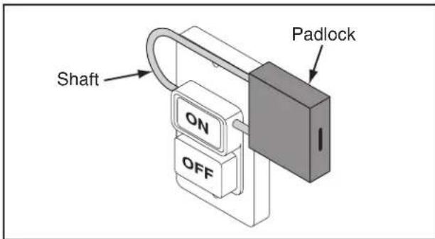
Disabling & Locking Switch
The ON/OFF switch can be disabled and locked by inserting a padlock through the ON button, as shown. Locking the switch in this manner can prevent unauthorized operation of the machine which is especially important if the machine is not stored inside an access-restricted building.
IMPORTANT: Locking the switch with a padlock only restricts its function. It is not a substitute for disconnecting power from the machine when adjusting or servicing.
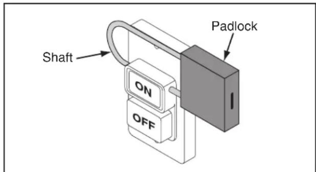
text_image
Shaft ON OFF PadlockFigure 42. Switch disabled by a padlock (sold separately).
WARNING
Children or untrained people can be seriously injured by this machine. This risk increases with unsupervised operation. To help prevent unsupervised operation, disable and lock the switch before leaving machine unattended! Place key in a well-hidden or secure location.
NOTICE
The padlock shaft diameter is important to the disabling function of the switch. With any padlock used to lock the switch, test the switch after installation to ensure that it is properly disabled.

text_image
0.12"-0.15"Workpiece Inspection
Some workpieces are not safe to cut or may require modification before they are safe to cut. Before cutting, inspect all workpieces for the following:
- Material Type: This machine is intended for cutting natural and man-made wood products, laminate covered wood products, and some plastics. Cutting drywall or cementitious backer board creates extremely fine dust and may reduce the life of the bearings. This machine is NOT designed to cut metal, glass, stone, tile, etc.; cutting these materials with a table saw may lead to injury.
- Foreign Objects: Nails, staples, dirt, rocks and other foreign objects are often embedded in wood. While cutting, these objects can become dislodged and hit the operator, cause kickback, or break the blade, which might then fly apart. Always visually inspect your workpiece for these items. If they can't be removed, DO NOT cut the workpiece.
- Large/Loose Knots: Loose knots can become dislodged during the cutting operation. Large knots can cause kickback and machine damage. Choose workpieces that do not have large/loose knots or plan ahead to avoid cutting through them.
- Wet or "Green" Stock: Cutting wood with a moisture content over 20% causes unnecessary wear on the blades, increases the risk of kickback, and yields poor results.
- Excessive Warping: Workpieces with excessive cupping, bowing, or twisting are dangerous to cut because they are unstable and often unpredictable when being cut. DO NOT use workpieces with these characteristics!
- Minor Warping: Workpieces with slight cupping can be safely supported if the cupped side is facing the table or the fence. On the contrary, a workpiece supported on the bowed side will rock during a cut and could cause kickback or severe injury.
Guide Post
The guide post, shown in the figure below, connects the upper blade guide assembly and blade guard to the bandsaw.
The guidepost allows these components to be positioned above the workpiece at a distance that provides the greatest support to the blade and minimizes operator exposure to the blade. We recommend positioning the blade guides so that they just clear the workpiece.
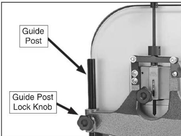
text_image
Guide Post Guide Post Lock KnobFigure 43. Guide post and lock knob.
To adjust the height of the guide post:
- Make sure that the blade tension, blade tracking, support bearings, and blade guide bearings are adjusted correctly.
- DISCONNECT BANDSAW FROM POWER!
- Loosen the guide post lock knob, then adjust the height of the guide post so that the blade guide assembly just clears the workpiece.
- Re-tighten the lock knob to secure the setting.
Table Tilt
The table can be tilted when making angle or bevel cuts.
Note: When tilting the table to the left, the positive stop bolt must be lowered. Be sure to re-adjust it when returning the table to be perpendicular with the blade.
To tilt the table:
- DISCONNECT BANDSAW FROM POWER!
- Loosen both table lock knobs underneath the table.
- Use the table tilt scale underneath the front of the table or a protractor against the table and blade to tilt the table to the desired degree, then re-tighten the lock knobs.
Blade Speed
The Model G0555/G0555P offers blade speeds of 1500 and 3200 FPM. For general woodworking and most cutting operations, we recommend using the 3200 FPM speed. Keep in mind, the results from different speeds are related to the type of workpiece, the blade being used for the operation, and the feed rate.
Use the chart below as a general guide to blade speed:
| Type of Cutting Operation | Blade Speed (FPM) |
| Most Species of Wood 3200 | |
| Super Dense Hardwood 1500 | |
| Fast/Average Feed Rate 3200 | |
| Requires Slow Feed Rate 1500 | |
| Rough Edges Acceptable 3200 | |
| Requires Smooth Edges | 1500 |
| Quick, Production Cuts | 3200 |
| Detailed, Intricate Cuts 1500 |
Speed changes are made by re-positioning the ribbed V-belt on the pulleys.
Tools Needed
Qty
Hex Wrench 6mm....1
To change the blade speed:
- DISCONNECT BANDSAW FROM POWER!
- Open the lower wheel cover and loosen the motor mount adjustment and hinge cap screws shown in Figure 44.
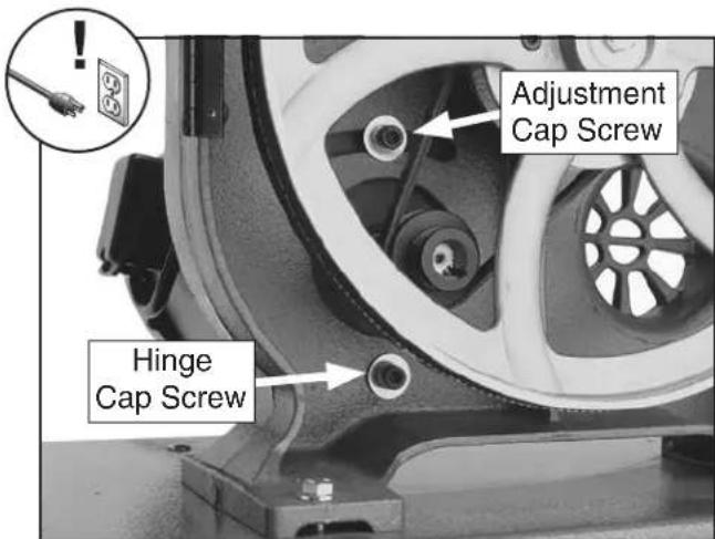
text_image
Adjustment Cap Screw Hinge Cap ScrewFigure 44. Locations of the motor adjustment and hinge cap screws.
- Move the motor so that the adjustment cap screw slides to the right of the slot. This will release the tension on the ribbed V-belt.
- Position the V-belt belt on the pulleys as illustrated in Figure 45 for the desired speed.
Note: Make sure the ribs of the V-belt are well seated in the pulley grooves.
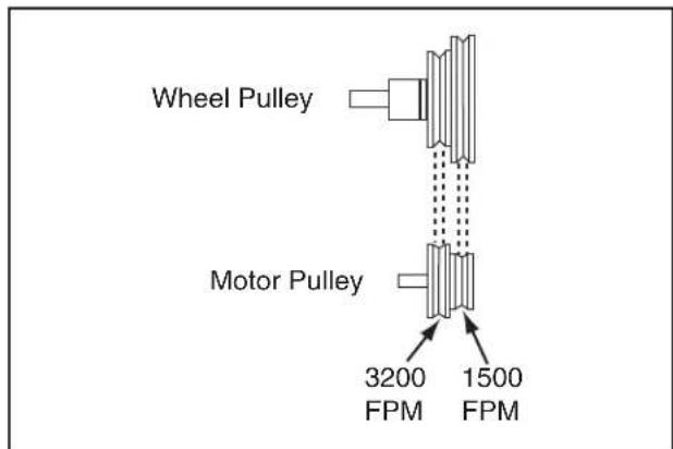
text_image
Wheel Pulley Motor Pulley 3200 1500 FPM FPMFigure 45. Drive belt position for the different speeds.
- Move the motor so that the adjustment cap screw slides to the left of the slot.
- Apply enough pressure on the motor so that there is approximately 14 " deflection of the V-belt with moderate pressure from your finger between the pulleys, then re-tighten the adjustment and hinge cap screws.
- Close the lower wheel cover before re-connecting the bandsaw to power.
Model G0555/G0555P (Mfg. Since 5/11)
Blade Information
Blade Dimensions
Length Range 92/2"-93 1/2"
Width Range .... ^1/8 “— ^3/4 ”
Selecting the right blade requires a knowledge of the various blade characteristics to match the blade with the particular cutting operation.
Blade Length
Measured by the circumference, blade lengths are usually unique to the brand of your bandsaw and the distance between wheels. Refer to the Accessories section later in this manual for blade replacements from Grizzly.
Blade Width
Measured from the back of the blade to the tip of the blade tooth (the widest point), blade width is often the first consideration given to blade selection. Blade width dictates the largest and smallest curve that can be cut, as well as how accurately it can cut a straight line.
Always pick the size of blade that best suits your application.
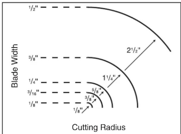
- Curve Cutting: Use the chart in the figure below to determine the correct blade for curve cutting. Determine the smallest radius curve that will be cut on your workpiece and use the corresponding blade width.
text_image
Blade Width 1/2" 3/8" 1/4" 3/16" 1/8" 21/2" 11/4" 5/8" 3/8" 1/8" Cutting RadiusFigure 46. Recommended cutting radius per blade width.
- Straight Cutting: Use the largest width blade that you own. Large blades excel at cutting straight lines and are less prone to wander.
Tooth Style
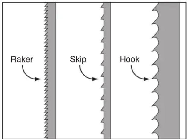
The figure below illustrates the three main blade tooth styles:
text_image
Raker Skip HookFigure 47. Main blade tooth styles.
- Raker: Considered to be the standard because the tooth size and shape are the same as the tooth gullet. The teeth on raker blades usually are very numerous, have no angle, and produce cuts by scraping the material. As a result, smooth cuts can be achieved without cutting fast or generating more heat than other tooth types.
- Skip: Similar to a raker blade that is missing every other tooth. Because of the design, skip toothed blades have a much larger gullet than raker blades, and therefore, cut faster and generate less heat. However, these blades also leave a rougher cut than raker blades.
- Hook: The teeth have a positive angle (downward) which makes them dig into the material, and the gullets are usually rounded for easier waste removal. These blades are excellent for the tough demands of resawing and ripping thick material.
Tooth Pitch
Measured as TPI (teeth per inch), tooth pitch determines the number of teeth. More teeth per inch (fine pitch) will cut slower, but smoother; while fewer teeth per inch (coarse pitch) will cut rougher, but faster. As a general rule, choose blades that will have at least three teeth in the material at all times. Use fine-pitched blades on harder woods and coarse-pitched blades on softer woods.
Blade Care
A bandsaw blade is a thin piece of steel that is subjected to tremendous stresses when cutting. You can obtain longer use from a bandsaw blade if you give it fair treatment and always use the appropriate feed rate for your operation. Be sure to select blades with the proper width, style, and pitch for each application. The wrong choice of blades will often produce unnecessary heat which will shorten the life of your blade.
A clean blade will perform much better than a dirty blade. Dirty or gummed up blades pass through the cutting material with much more resistance than clean blades. This extra resistance also causes unnecessary heat. Resin/pitch cleaners are excellent for cleaning dirty blades.
Blade Breakage
Many conditions may cause a bandsaw blade to break. Blade breakage is unavoidable, in some cases, since it is the natural result of the peculiar stresses that bandsaw blades are subjected to. Blade breakage is also due to avoidable circumstances. Avoidable breakage is most often the result of poor care or judgement on the part of the operator when mounting or adjusting the blade or blade guides.
The most common causes of blade breakage are:
- Faulty alignment/adjustment of the guides.
- Forcing/twisting a wide blade around a short radius.
- Feeding the workpiece too fast.
- Dull teeth or damaged tooth set.
• Over-tensioned blade. - Upper blade guide assembly set too high above the workpiece.
- Using a blade with a lumpy or improperly finished braze or weld.
- Continuously running the bandsaw when not in use.
• Leaving blade tensioned when not in use. - Using the wrong TPI for the workpiece thickness. (The general rule of thumb is three teeth in the workpiece at all times.)
Blade Change
natural_image
Illustration of an electrical plug and a wall socket with warning symbols (no text or labels)WARNING
Always disconnect power to the machine when changing blades. Failure to do this may result in serious personal injury.

natural_image
Silhouette of a hand pointing to three droplets (no text or symbols)CAUTION
Bandsaw blades are sharp and can quickly cut fingers and hands. To reduce the risk of this type of injury, ALWAYS wear heavy leather gloves when handling these blades.
Blade Removal
- DISCONNECT BANDSAW FROM POWER!
- Move the blade tension quick release lever up to release blade tension.
- Adjust the upper blade guide assembly all the way up and move the blade guides completely away from the blade.
- Remove the fence and miter gauge from the table, then remove the table insert and the table pin.
- Open the upper and lower wheel covers.
- Put on heavy leather gloves, then slip the blade off the wheels, rotate it 90°, and slide it through the table slot and off the machine.
Blade Installation
- DISCONNECT BANDSAW FROM POWER!
- Perform Steps 2–6 in the previous Blade Removal procedure.
- Put on heavy leather gloves, position the blade so that the teeth are facing to the right and down toward the table, then slide it through the table slot.
Note: If the teeth will not point downward in any orientation, the blade is inside-out. Remove the blade and twist it right side-out.
- Rotate the blade 90^ , then slip it over the wheels while making sure it is properly positioned between the blade guards and guides.
- Use the blade tension adjustment knob to bring the red marker to the correct blade width mark on the tension scale, then pull the blade tension quick release lever down to the horizontal position.
—If you are having difficulty pulling the quick release lever down or the blade is a different length from the previous blade, adjust the blade tensioner as instructed in the Blade Tensioner subsection on Page 53. Then, continue with Step 6.
—If you successfully pull the quick release lever down and the blade is properly tensioned, continue with Step 6.
- Check and adjust the blade tracking.
- Adjust the support bearings and the upper/lower blade guides.
- Close the wheel covers, and replace the table insert and table pin.
Basic Cutting Tips
Here are some basic tips to follow when operating the bandsaw:
- Replace, sharpen, and clean blades as necessary. Make adjustments periodically to keep the saw running in top condition.
- Use light and even pressure while cutting. Light contact with the blade eases line following and prevents undue friction.
- Avoid twisting the blade when cutting around tight corners. Allow the blade to saw around the corners.
- Misusing the saw or using incorrect techniques is unsafe and results in poor cuts. Remember—the blade does the cutting with the operator's guidance.
Cutting Options
The bandsaw is capable of performing the following cuts:
- Mites • Compound Angles
- Angles • Complex Curves
- Resaw • Duplicate Parts
- Ripping • Circles
• Crosscutting • Beveled Curves
Ripping
"Ripping" means cutting with the grain of the wood stock. For plywood and other processed wood, ripping simply means cutting down the length of the workpiece.
To make a rip cut:
- Adjust the fence to match the width of the cut on your workpiece, then lock the fence in place.
- Adjust the blade guide assembly to the proper height above the workpiece.
- After all safety precautions have been met, turn the bandsaw ON and wait for it to come to full speed. Slowly feed the workpiece into the blade and continue with the cut until the blade is completely through the workpiece. The figure below shows an example of a ripping operation.
Note: If you cut narrow pieces, use a push stick to protect your fingers.
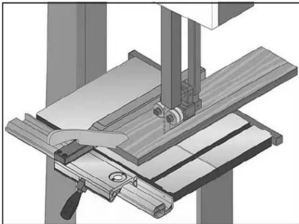
natural_image
Mechanical assembly diagram showing a cutting machine with wooden components and a tool (no text or symbols visible)Figure 48. Example of a ripping operation.
WARNING
NEVER place fingers or hands in the line of cut. If you slip, your hands or fingers may go into the blade. ALWAYS use a push stick when ripping narrow pieces. Failure to follow these warnings may result in serious personal injury!
Crosscutting
Crosscutting is the process of cutting across the grain of wood. For plywood and other processed wood, crosscutting simply means cutting across the width of the material.
To make a 90° crosscut:
- Mark the workpiece on the edge where you want to begin the cut.
- Adjust the blade guide assembly to the correct height and make sure the miter gauge is set to 0^ (or other angle for angled cuts).
- Move the fence out of the way. Place the workpiece evenly against the miter gauge, then line up the mark with the blade.
- After all safety precautions have been met, turn the bandsaw ON and wait for it to come to full speed. Slowly feed the workpiece into the blade and continue the cut until the blade is all the way through the workpiece. The figure below shows an example of a crosscutting operation.
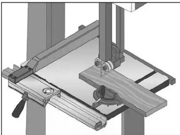
natural_image
Mechanical assembly diagram showing a cutting machine with wooden base and workpiece (no text or symbols)Figure 49. Example of a crosscutting operation with the miter gauge.
Resawing
"Resawing" means cutting the thickness of a board into two or more thinner boards (see the figure below for an example). The maximum board width that can be resawn is limited by the maximum cutting height of the bandsaw.
One of the most important considerations for resawing is blade selection—a wide blade cuts straighter and is less prone to blade lead (see the Blade Lead subsection later in this manual for more information).
For most applications, use a blade with a hook or a skip tooth style. Choose blades with fewer teeth-per-inch (from 3 to 6 TPI), because they offer larger gullet capacities for clearing sawdust, reducing heat buildup, and reducing strain on the motor.
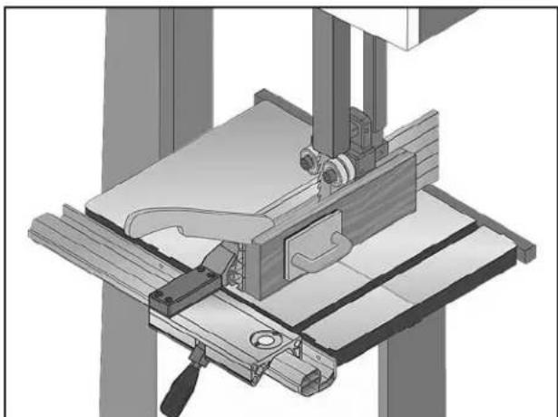
natural_image
Mechanical assembly diagram showing a clamping device mounted on a workbench with no visible text or symbolsFigure 50. Example of a resawing operation.
WARNING
When resawing thin pieces, a wandering blade (blade lead) can tear through the side of the workpiece, exposing your hands to the blade teeth. Always use push blocks when resawing and keep your hands clear of the blade.
Cutting Curves
When cutting curves, simultaneously feed and turn the stock carefully so that the blade follows the layout line without twisting. Use either a narrower blade or a blade with more TPI (teeth per inch), or make more relief cuts, to avoid having to back the workpiece away from the blade, especially if the curve is sharp.
Always make short cuts first, then proceed to the longer cuts. Relief cuts will also reduce the chance that the blade will be pinched or twisted. Relief cuts are cuts made through the waste portion of the workpiece and are stopped at the layout line. As you cut along the layout line, waste wood is released from the workpiece, alleviating any pressure on the back of the blade. Relief cuts also make backing the workpiece out easier once the saw blade has come to a stop, if needed.
NOTICE
The list below displays blade widths and the corresponding minimum radii for those blade widths.
Width Min. Radius
| 1/8" | 1/8" |
| 3/16" | 3/8" |
| 1/4" | 5/8" |
| 3/8" | 1^1/4" |
| 1/2" | 2^1/2" |
| 5/8" | 3^3/4" |
| 3/4" | 5^1/2" |
Stacked Cuts
One of the benefits of a bandsaw is its ability to cut multiple copies of a particular shape by stacking a number of workpieces together. Before making stacked cuts, ensure that the table is perpendicular (90°) to the blade—otherwise, any error in this setting will be compounded in the upper workpieces.
To complete a stacked cut:
- Align your pieces from top to bottom to ensure that each piece has adequate scrap to provide a clean, unhampered cut.
- Secure all the pieces together in a manner that will not interfere with the cutting. Hot glue on the edges works well, as do brad nails through the waste portion. (Be careful not to cut into the brads or you may break the blade!)
- On the face of the top piece, lay out the shape you intend to cut.
- Make relief cuts perpendicular to the outline of your intended shape in areas where changes in blade direction could strain the woodgrain or cause the blade to bind.
- Cut the stack of pieces as though you were cutting a single piece. Follow your layout line with the blade kerf on the waste side of your line (see the figure below for an example of stacked cut setup).
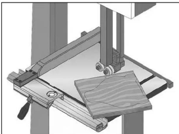
natural_image
Mechanical assembly diagram showing a clamping device with wooden base and workpiece (no text or symbols)Figure 51. Example of a stacked cut setup.
SECTION 5: ACCESSORIES
WARNING
Some aftermarket accessories can be installed on this machine that could cause it to function improperly, increasing the risk of serious personal injury. To minimize this risk, only install accessories recommended for this machine by Grizzly.
NOTICE
Refer to the newest copy of the Grizzly Catalog for other accessories available for this machine.
Call 1-800-523-4777 To Order
Order Online at grizzly.com®
H3051—6" Extension Block Kit for G0555 H3051P—6" Extension Block Kit for G0555P
Increase your cutting capacity from 6" to 12" cutting height with this bolt-on 6" extension block kit. Includes all necessary hardware plus extended blade guard and 105" x ^3/8 " x 6 TPI blade. We also carry a full line of 105" blades!
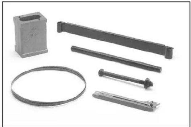
natural_image
Collection of mechanical parts including a bracket, elongated ring, and multiple metal fasteners (no text or symbols visible)Figure 52. H3051 Extension Block Kit.
Bandsaw Blades
Grizzly bandsaw blades are made from top quality saw steel manufactured to precise tolerances with guaranteed welds for blades that last longer and produce smoother cuts.
| Model Length Width TPI Gauge | ||||
| G5152 93 | 12" | 18" 14 | Raker 0 | 025 |
| G5153 93 | 12" | 18" 18 | Raker 0 | 025 |
| G5154 93 | 12" | 316" | 4 Skip 0 | 025 |
| G5155 93 | 12" | 316" | 10 Raker | 0.025 |
| G5156 93 | 12" | 316" | 14 Raker | 0.025 |
| G5157 93 | 12" | 14" | 4 Hook | 0.025 |
| G5158 93 | 12" | 14" | 6 Hook | 0.025 |
| G5159 93 | 12" | 14" 10 | Raker 0 | 025 |
| G5160 93 | 12" | 14" 14 | Raker 0 | 025 |
| G5161 93 | 12" | 14" 18 | Raker 0 | 025 |
| G5162 93 | 12" | 38" | 4 Hook | 0.025 |
| G5163 93 | 12" | 38" | 6 Hook | 0.025 |
| G5164 93 | 12" | 38" 10 | Raker 0 | 025 |
| G5165 93 | 12" | 38" 14 | Raker 0 | 025 |
| G5166 93 | 12" | 12" | 3 Hook | 0.025 |
| G5167 93 | 12" | 12" | 4 Hook | 0.025 |
| G5168 93 | 12" | 12" | 6 Hook | 0.025 |
| G5169 93 | 12" | 12" 10 | Raker 0 | 025 |
| G5170 93 | 12" | 12" 14 | Raker 0 | 025 |
| G5171 93 | 12" | 34" | 3 Hook | 0.025 |
| G5172 93 | 12" | 34" | 6 Hook | 0.025 |
| G5173 93 | 12" | 34" 10 | Raker 0 | 025 |
G1928—Bandsaw Handbook
This is the bandsaw bible. Covers step-by-step instructions for basic/advanced cutting techniques. Also includes advanced maintenance, service and troubleshooting procedures, as well as information on bandsaw history/design and blade metallurgy. 320 pages.

text_image
BAND SAW HANDBOOK Mark DuginskeFigure 53. Bandsaw handbook.
G7315Z—Super Heavy-Duty SHOP FOX® Mobile Base
This patented, super heavy-duty mobile machine base is the strongest mobile base on the market. 18" x 24 12 " minimum and adjusts to 28 12 " x 33 12 ". Maximum 1200 lb. capacity. This base is extremely stable with outrigger type supports and a four wheel system. Weighs 38 lbs.
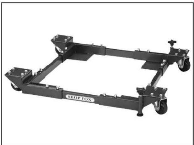
natural_image
Black industrial machine frame with wheels and a 'SHOP FOX' label (no other text or symbols visible)Figure 54. G7315Z SHOP FOX® Mobile Base.
T10117—Big Mouth Dust Hood with Stand
Capture dust from any machine operation with this Big Mouth Dust Hood. Simply attach a 4" dust collection hose and adjust the hood right where you need it. The free standing base eliminates complicated machine setups and the tilting 16 38 " x 12 78 " hood adjusts from 23" to 43" high. Every shop needs one of these!

natural_image
Modern medical imaging station with monitor and stand (no visible text or symbols)Figure 55. T10117 Big Mouth Dust Hood.
Order Online at grizzly.com®
G1163P—1HP Floor Model Dust Collector G0710—1HP Wall-Mount Dust Collector G3591—30 Micron Replacement Bag H4340—3.0 Micron Upgrade Bag
Excellent point-of-use dust collectors that can be used next to the machine with only a small amount of ducting. Specifications: 450 CFM, 7.2" static pressure, 2 cubic foot bag, and 30 micron filter. Motor is 1HP, 110V/220V, 14A/7A.

text_image
Model G0710 Model G1163PFigure 56. Point-of-use dust collectors.
H7584—Re-Saw Fence Retrofit Kit
This retrofit kit allows you to upgrade your existing aluminum fence for the G0555/G0555P bandsaw to a cast-iron fence with the 6" high re-saw fence. Simply unbolt your existing aluminum fence (4 bolts) and bolt on the new cast-iron fence. Takes less than 3 minute to switch over.
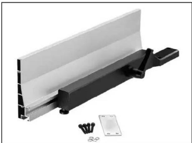
natural_image
Exterior view of a mechanical assembly with black and white components, no visible text or symbolsFigure 57. H7584 Re-Saw Fence Retrofit Kit for the G0555/G0555P Bandsaw.
Call 1-800-523-4777 To Order
SECTION 6: MAINTENANCE
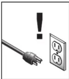
natural_image
Electrical outlet with a power plug and warning symbol (no text or labels)WARNING
ALWAYS disconnect power to the machine before performing maintenance. Failure to do this may result in serious personal injury.
Schedule
For optimum performance from your machine, follow this maintenance schedule and refer to any specific instructions given in this section.
Daily
- Check/correct loose mounting bolts.
- Check/correct damaged or worn saw blade.
- Check/correct worn or damaged wires.
- Correct any other unsafe condition.
Monthly
- Check for V-belt tension, damage, or wear.
- Remove blade and thoroughly clean all built-up sawdust from the wheels and rubber tires. If necessary, re-dress the rubber tires.
- Clean/vacuum dust buildup from inside wheel covers and off the motor.
Cleaning & Protecting
Cleaning the bandsaw is relatively easy. Vacuum away excess wood chips and sawdust, and wipe off the remaining dust with a dry cloth. If any resin has built up, use a resin dissolving cleaner to remove it.
Protect the unpainted cast iron surfaces on the table by wiping the table clean after every use—this ensures moisture from wood dust does not remain on bare metal surfaces.
Keep the table rust-free with regular applications of products like G96 ^® Gun Treatment, SLIPIT ^® , or Boeshield ^® T-9 (contact Grizzly to purchase these products).
Lubrication
The bearings on this bandsaw are pre-lubricated and sealed at the factory, and require no lubrication for the life of the bearings. All bearings are standard sizes, and replacements can be purchased from our parts department or a bearing supply store.
As for other items on this machine, such as adjustment controls, an occasional “shot” of light oil is just about all that is necessary. Before applying, however, wipe off any sawdust with a clean cloth, towel or dry paint brush, then spray on the lubricant.
Ensure that lubricant does not get on the pulleys or V-belt, which could cause V-belt deterioration or loss of power transfer due to slippage.
Redressing Rubber Tires
As the bandsaw ages, the rubber tires on the wheels may need to be redressed if they harden or glaze over. Redressing the rubber tires improves blade tracking and reduces vibration/blade lead.
If the rubber tires become too worn, then blade tracking will become extremely difficult. At that point, redressing will no longer be effective and the rubber tires must be replaced.
To redress the rubber tires:
- DISCONNECT BANDSAW FROM POWER!
- Put on heavy leather gloves.
- Remove the blade.
- Clean any built-up sawdust from the rubber tires and wheels.
- Hold 100 grit sandpaper against the rubber tire and rotate the wheel by hand. Only redress the rubber enough to expose a fresh rubber surface.
- Re-install the blade, then make sure the blade tracking and tension are correct.
SECTION 7: SERVICE
Review the troubleshooting and procedures in this section if a problem develops with your machine you need replacement parts or additional help with a procedure, call our Technical Support. Note: Please gather the serial number and manufacture date of your machine before calling.
Troubleshooting
Motor & Electrical
| Symptom Possible Cause Possible Solution | ||
| Machine does not start or a breaker trips. | 1. Power supply is at fault/switched OFF.2. Plug/receptacle is at fault or wired incorrectly.3. Wiring is open/has high resistance.4. Motor connection wired incorrectly.5. Start capacitor is at fault (110V only).6. Motor ON/OFF switch is at fault.7. Centrifugal switch is at fault. | 1. Ensure hot lines have correct voltage on all legs and main power supply is switched ON.2. Test for good contacts; correct the wiring.3. Check for broken wires or disconnected/corroded connections, and repair/replace as necessary.4. Correct motor wiring connections (Page 56).5. Test/replace.6. Replace faulty ON/OFF switch.7. Adjust/replace centrifugal switch. |
| Machine stalls or is underpowered. | 1. Incorrect workpiece material.2. Feed rate too fast for task.3. V-belt slipping.4. Motor connection is wired incorrectly.5. Plug/receptacle is at fault.6. Motor bearings are at fault.7. Motor has overheated.8. Motor is at fault.9. Centrifugal switch is at fault. | 1. Use wood with correct moisture content (20% or less), without glues, and little pitch/resin.2. Decrease feed rate.3. Tighten/repair/replace (Pages 47 and 48).4. Correct motor wiring connections (Page 56).5. Test for good contacts; correct the wiring.6. Test by rotating shaft; rotational grinding/loose shaft requires bearing replacement.7. Clean off motor, let cool, and reduce workload.8. Test/repair/replace.9. Adjust/replace centrifugal switch. |
| Machine has vibration or noisy operation. | 1. Motor or component is loose.2. V-belt worn or loose.3. Motor fan is rubbing on fan cover.4. Pulley is loose.5. Machine is incorrectly mounted or sits unevenly on floor.6. Blade is at fault.7. Cast iron motor mount loose/broken.8. Centrifugal switch is at fault.9. Motor or spindle bearings are at fault. | 1. Inspect/replace stripped or damaged bolts/nuts, use thread locking fluid, and retighten.2. Tension V-belt (Page 47) or replace V-belt (Page 48).3. Replace dented fan cover; replace damaged fan.4. Tighten pulley set screw.5. Adjust stand feet.6. Replace blade.7. Tighten/replace.8. Adjust/replace centrifugal switch..9. Test by rotating shaft; rotational grinding/loose shaft requires bearing replacement. |
Cutting Operations

| Symptom Possible Cause Possible Solution | ||
| Machine slows when operating. | 1. Feeding workpiece too fast.2. Blade is dull. | 1. Reduce feed rate.2. Replace blade (Page 37). |
| Ticking sound when the saw is running. | 1. Blade weld contacting guide/support bearings (a light tick is normal).2. Blade weld may be failing. | 1. Use file or stone to smooth and round the back of the blade; slightly loosen the blade guides.2. Inspect and replace blade if necessary (Page 37). |
| Blade contacting table insert. | 1. Insert installed upside down or backwards.2. Table improperly mounted or aligned. | 1. Re-install insert a different way.2. Align table (Page 29). |
| Vibration when cutting. | 1. Loose or damaged blade.2. Sawdust buildup on wheels. | 1. Tighten or replace blade (Page 37).2. Clean all sawdust from rubber tires on wheels. |
| Burn marks on the edge of the cut. | 1. Too much side pressure when feeding workpiece; blade is binding.2. Blade too wide for size of radius being cut. | 1. Feed workpiece straight into the blade.2. Install a smaller width blade/increase blade tension (Page 35). |
| Rough or poor quality cuts. | 1. Feeding workpiece too fast.2. Blade guides adjusted incorrectly. | 1. Reduce feed rate.2. Re-adjust all blade support and guide bearings (Pages 25 and 26). |
| Sawdust buildup inside wheel covers. | 1. Clogged dust port.2. Low CFM (airflow) from dust collection system. | 1. Clean out dust port.2. Three options:—Check dust lines for leaks or clogs.—Move dust collector closer to saw.—Install a more powerful dust collector. |
| Blade wanders or doesn't cut straight. | 1. Blade lead.2. Sawdust buildup on wheels. | 1. Refer to Blade Lead on Page 52.2. Clean all sawdust from rubber tires on wheels. |
| Cuts are not square (vertically). | 1. Table tilt is not adjusted to 0^ or positive stop has moved out of adjustment.2. Table tilt scale pointer is not calibrated.3. Table is not square to the blade. | 1. Adjust table tilt to 0^ ; readjust positive stop if necessary (Page 28).2. Calibrate table tilt scale pointer to 0^ (Page 28).3. Shim table (Page 48). |
Miscellaneous
| Symptom Possible Cause Possible Solution | ||
| Tensioner mechanism has poor range of motion. | 1. Spacer blocks on quick-release tension mechanism have moved out of adjustment. | 1. Reset the blade tensioner (Page 53). |
| Blade tension scale is grossly inaccurate. | 1. The spring in the blade tension mechanism has lost its "spring." This is caused by not releasing the blade tension when not in use or frequently over-tensioning the bandsaw. | 1. Replace spring in the blade tension mechanism, then take better care of the bandsaw by releasing tension when not in use and not over-tensioning the blade. |
| Wheel is noisy. | 1. Wheel bearing is worn out.2. V-belt is too tight (lower wheel). | 1. Replace the wheel bearing.2. Check/loosen the belt tension (Page 47). |
| Blade does not track consistently, correctly, or at all. | 1. Wheels are not coplanar or aligned with each other.2. Rubber tires on wheels are worn out. | 1. Adjust wheels to be coplanar/aligned with each other (Page 49).2. Redress the rubber tires on the wheels (Page 44) replace the rubber tires on the wheels. |
V-Belt Tension
To ensure optimum power transmission from the motor to the blade, the V-belt must be in good condition and operate under proper tension.
V-belt tension should be checked at least every month—more often if the bandsaw is used daily. If the belt shows signs of cracks, fraying, and excessive wear, replace it as instructed in the Service section later in this manual.
Checking V-Belt Tension
-
DISCONNECT BANDSAW FROM POWER!
-
Open the lower wheel cover.
-
The V-belt is properly tensioned if there is approximately 14 " deflection of the V-belt when you apply moderate pressure to it between the pulleys (see the illustration in the following figure).
— If the V-belt is not properly tensioned, perform the following Tensioning V-Belt procedure.
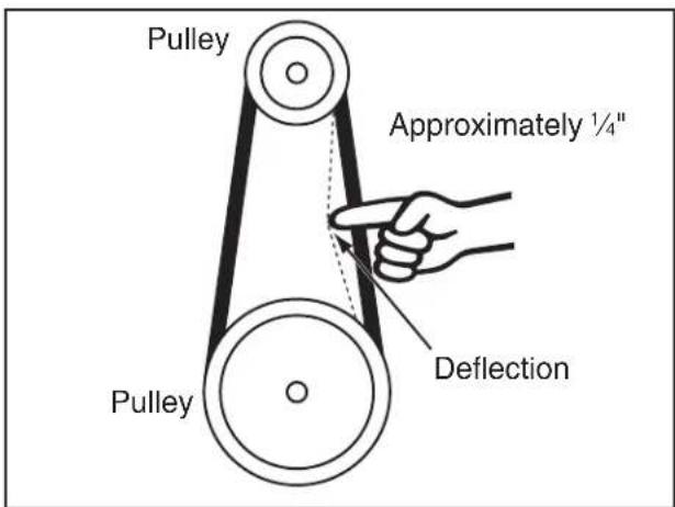
text_image
Pulley Approximately ¼" Pulley DeflectionFigure 58. Checking the V-belt tension.
Tensioning V-Belt
Tool Needed Qty Hex Wrench 6mm....1
To properly tension the V-belt:
-
DISCONNECT BANDSAW FROM POWER!
-
Open the lower wheel cover and loosen the motor adjustment and hinge cap screws shown in Figure 59.
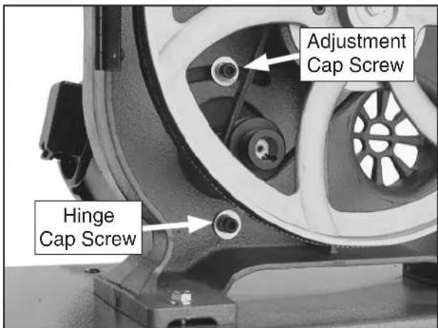
text_image
Adjustment Cap Screw Hinge Cap ScrewFigure 59. Locations of the motor adjustment and hinge cap screws.
-
Push the motor to the left (as viewed from the front of the machine) until there is approximately 14 " deflection in the V-belt between the pulley when moderate pressure is applied.
-
Re-tighten both cap screws and close the wheel cover.
Replacing V-Belt
To ensure optimum power transmission from the motor to the blade, the V-belt must be in good condition and operate under proper tension.
If the belt shows signs of cracks, fraying, and excessive wear, replace it.
Tools Needed Qty
Hex Wrench 6mm ....1
Wrench or Socket 13mm....1
Replacement V-Belt (Part No. P0555068) .....1
To replace the V-belt:
- DISCONNECT BANDSAW FROM POWER!
- Put on heavy leather gloves and remove the blade from the machine.
- Loosen the motor adjustment and hinge cap screws shown in Figure 60.
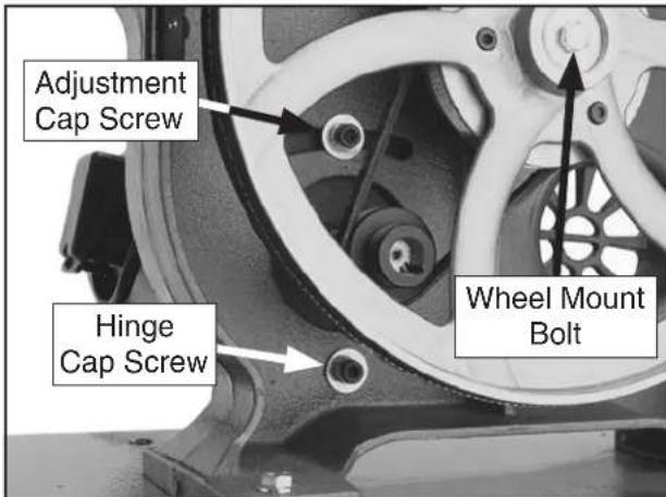
text_image
Adjustment Cap Screw Hinge Cap Screw Wheel Mount BoltFigure 60. Locations of the wheel mount bolt, and motor adjustment and hinge cap screws.
- Move the motor to the right (as viewed from the front of the bandsaw) so that the adjustment cap screw slides to the right in the slot—this will release the V-belt tension.
-
Roll the V-belt off the pulleys.
-
Unthread the wheel mount bolt clockwise (left-hand thread), and remove it and the flat washer from the wheel hub.
- Taking care not to misplace the shaft key, slide the wheel from the shaft.
- Align the wheel keyway with the shaft key and slide the wheel back onto the shaft.
- Secure the wheel with the wheel mount bolt and flat washer.
- Position the V-belt on the desired pulleys, then properly tension it, as instructed in the V-Belt Tension subsection on Page 47.
- Replace the blade, then properly track and tension it (see Pages 21 and 24).
Shimming Table
To ensure accuracy when cutting stacked cuts or circles, the table must be 90^ to the back of the blade, as shown in the figure below.
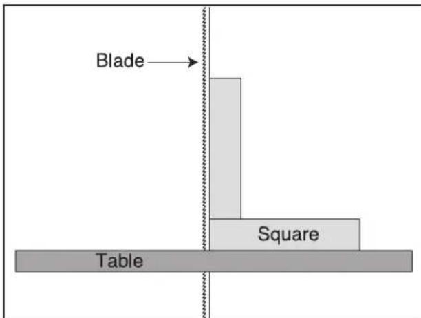
text_image
Blade Table SquareFigure 61. Checking the table to be perpendicular to the back of the blade.
If the table is not perpendicular to the back of the blade, correct this condition by placing shim stock between the table and trunnions underneath it.
Tip: For fine adjustments, use electrical washers on the bolts that secure the table.
Wheel Alignment
Wheel alignment is one of the most critical factors for optimal performance from your bandsaw. Wheels are properly aligned when they are parallel with each other and in the same plane or "coplanar" (see the illustration in the figure to the right).
Heat, vibration, wandering, blade wear, tire wear and overall bandsaw wear are considerably decreased when the wheels are parallel and coplanar. Additionally, wheels that are parallel and coplanar automatically track the blade by balancing it on the crown of the wheel—this is known as “coplanar tracking.”
Bringing the wheel into alignment may require a combination of shimming a wheel and center/lateral tracking the upper blade.
Tools Needed Qty
Straightedge 4 ft. 1
Fine Ruler 1
Wrench or Socket 13mm....1
Wrench or Socket 19mm ....1
Checking Wheel Alignment
- DISCONNECT BANDSAW FROM POWER!
- Remove the table.
- With the blade on and properly tensioned, hold a straightedge close to the center of both wheels. Make sure the straightedge fully extends across the rims of both wheels, as shown in the figure below.
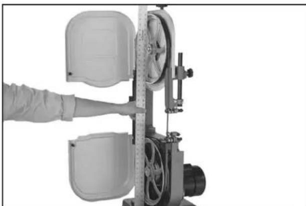
natural_image
Person operating a mechanical device with a ruler, no visible text or symbolsFigure 62. Checking if the wheels are coplanar.
Model G0555/G0555P (Mfg. Since 5/11)
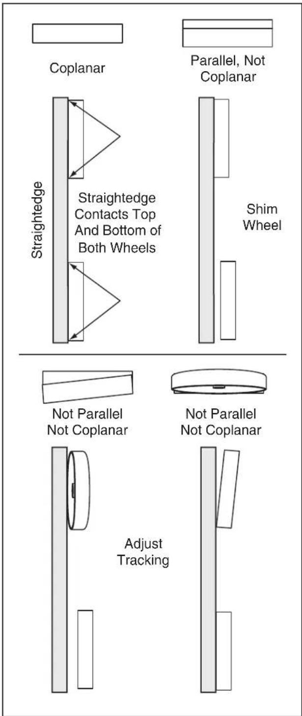
text_image
Coplanar Straightedge Straightedge Contacts Top And Bottom of Both Wheels Parallel, Not Coplanar Shim Wheel Not Parallel Not Coplanar Not Parallel Not Coplanar Adjust TrackingFigure 63. Wheel alignment illustration.
— If the wheels are parallel and coplanar, the straightedge will touch the top and bottom rims on both wheels. No further adjustment is required.
— If the wheels are parallel but not coplanar, the straightedge will touch the top and bottom rims on one wheel, but will not touch either rim on the other wheel. In this case, shim the wheel that does not touch the straightedge, as instructed in the following Shimming a Wheel procedure.
— If the wheels are not coplanar, the straight-edge will touch both rims of one wheel, but at an angle to the other wheel. In this case, you will need to adjust the tracking of the upper wheel.
If the upper wheel is tilted from top to bottom only, perform the Center Blade Tracking procedure as instructed earlier in this manual.
If the upper wheel is tilted from side to side, perform Upper Wheel Lateral Adjustment procedure that follows.
Shimming a Wheel
A wheel that is parallel with the other wheel, but is not coplanar, must be shimmed by the distance that it is not in the same plane with the other wheel.
To shim a wheel:
- DISCONNECT BANDSAW FROM POWER!
-
Adjust the upper wheel tracking so that it is parallel with the bottom wheel.
-
With the straightedge touching both rims of the wheel that does not need to be adjusted, measure the distance away from the other wheel with a fine ruler, as shown in the figure below. The distance measured with the ruler is the distance this wheel must be shimmed.
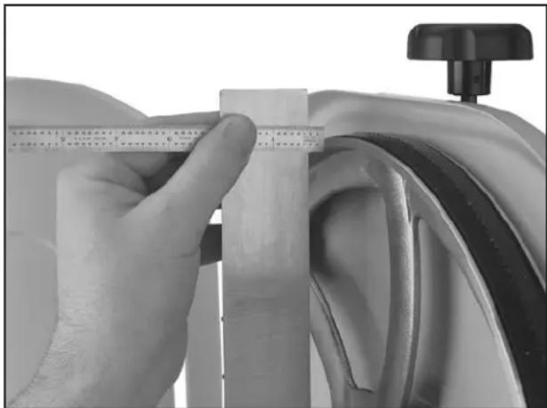
natural_image
Close-up of a hand measuring a wooden ruler on a car wheel, with a small mechanical component visible nearby (no text or symbols)Figure 64. Measuring the distance to shim the wheel to be coplanar.
- Remove the wheel to be shimmed, then place shimming washers in the amount measured in Step 3 onto the wheel shaft.
- Re-install the wheel and secure it in place.
- Re-install the blade, then properly tension it for operation.
Note: Often the wheels may be coplanar with the blade loose, then be pulled out of alignment when it is tightened.
- Perform the previous Checking Wheel Alignment procedure. If necessary to make the wheels parallel, repeat this procedure.
- When you are satisfied with the adjustment, re-install the blade and close the wheel covers.
Upper Wheel Lateral Adjustment
If the upper wheel is tilted laterally (side to side), perform the following procedure to make it coplanar with the lower wheel.
There are two set screws in the upper wheel bracket, shown in Figures 65–66, that adjust the wheel tilt from side to side.
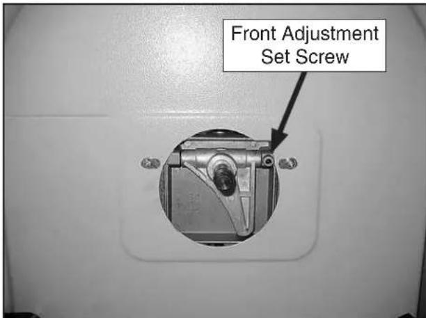
text_image
Front Adjustment Set ScrewFigure 65. Front lateral adjustment set screw (viewed with the upper wheel removed).
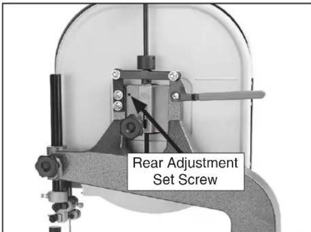
text_image
Rear Adjustment Set ScrewFigure 66. Rear lateral adjustment set screw.
Tools Needed Qty
Hex Wrench 2.5mm 1
Wrench or Socket 19mm ....1
To adjust the upper wheel laterally:
-
DISCONNECT BANDSAW FROM POWER!
-
Remove the blade from the machine.
-
Remove the hex nut that secures the upper wheel, then slide the wheel from the shaft.
-
Thread one set screw out and thread the other set screw in the same amount to tilt the wheel laterally.
For instance, to tilt the right side of the upper wheel back, thread the rear set screw out and thread the front set screw in the same amount.
- Slide the upper wheel back on the shaft, then repeat the Checking Wheel Alignment procedure and, if necessary, repeat this procedure until the upper wheel is coplanar with the lower wheel.
Blade Lead
Bandsaw blades may wander off the cut line when sawing, as shown in the figure below. This is called blade lead.
Blade lead is usually caused by too fast of a feed rate, a dull or abused blade, or improper blade tension. If your blade is sharp/undamaged, properly tensioned, and you still have blade lead, perform the following procedures.
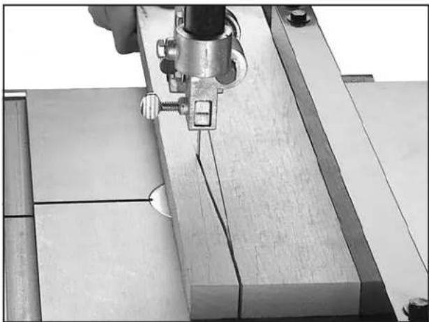
natural_image
Close-up of a mechanical assembly with a metal clamp and wooden base, no visible text or symbolsFigure 67. Example of blade lead.
To correct blade lead:
- Make sure the blade is properly tensioned and the blade guides are adjusted correctly.
- Use less pressure when feeding the workpiece through the cut—this will reduce the feed rate.
- Make sure the miter slot and fence are parallel to the blade line (see the Aligning Table and Aligning Fence procedures in this manual for detailed information).
- If after Steps 1–3 there is still blade lead present, compensate for this condition by skewing the fence or shifting the table, as instructed in the following procedures.
To skew your fence:
-
Cut a piece of scrap wood approximately 34 " thick x 3" wide x 17" long. On the wide face of the board, draw a straight line parallel to the long edge.
-
Slide the bandsaw fence out of the way and cut halfway through the board on the line by pushing it into the blade. Turn the bandsaw OFF and wait for the blade to stop. Do not move the board.
-
Clamp the board to the bandsaw table, then slide the fence over to the board so it barely touches one end of the board.
-
Use a 4mm hex wrench to loosen the four fence adjustment cap screws on top of the fence, skew the fence so that it is parallel with the scrap piece, then re-tighten the cap screws.
-
Make a few cuts using the fence.
— If blade lead is still present, repeat Steps 1–4 until the blade and fence are parallel with each other.
— Or, shift the table, as instructed in the following procedure.
To shift the table:
-
On a scrap piece of wood, mark a line that is perpendicular to the front edge.
-
Cut halfway through the board on the line by pushing it into the blade.
-
Turn the bandsaw OFF and wait for the blade to stop.
-
Disconnect the bandsaw from power, then use a 10mm wrench to loosen the six hex bolts underneath the table that secure it to the trunnion brackets.
-
Shift the table to compensate for the blade lead, re-tighten the hex bolts, then re-connect the bandsaw to power.
-
Repeat Steps 1–5 until there is no longer any blade lead.
Blade Tensioner
The blade tensioner may need to be reset for one of the following reasons:
- The blade tension quick release lever will not move down into the horizontal position when the tension scale is correctly adjusted for the installed blade.
- You have installed a blade of a different length.
Tool Needed Qty
Hex Wrench 2.5mm 1
To reset the blade tensioner:
- DISCONNECT BANDSAW FROM POWER!
- Move the blade tension lever up to the vertical position to release blade tension, then loosen the set screws on both spacers shown in Figure 68.
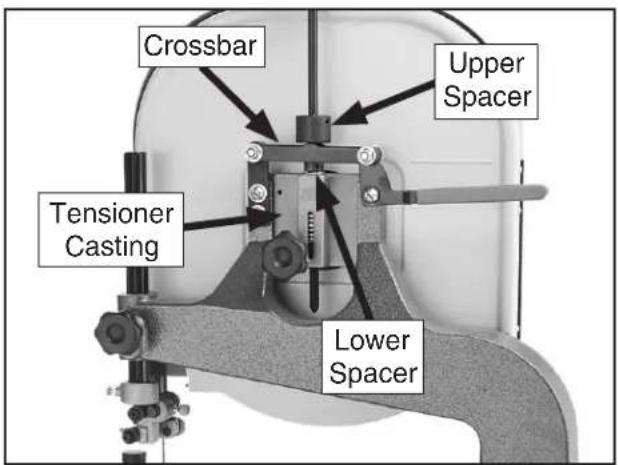
text_image
Crossbar Upper Spacer Tensioner Casting Lower SpacerFigure 68. Locations of spacers and tensioner crossbar.
- Rotate the spacers fully away from the cross-bar, then rotate the blade tension knob so that the red marker is at the blade width mark for the installed blade.
- Pull the quick release lever down to the horizontal position.
- Pull up on the tension knob to apply as much tension on the blade as possible.
- While maintaining the upward pressure on the tension knob, thread the upper spacer down until it touches the crossbar, then re-tighten the set screw to secure it in place.
- Thread the lower spacer down until it touches the top of the tensioner casting, then thread it back up 1–2 turns to leave a small space above the casting and re-tighten the set screw to secure the setting.
- Move the quick release lever up to the vertical position and make sure there is no tension on the blade. If all the tension is not released, the lower spacer needs to be threaded farther down the shaft toward the tensioner casting.
Fence Scale Calibration
You may need to recalibrate the fence scale after changing or adjusting the blade, or if the scale is not producing accurate cuts. Recalibrate the fence scale by adjusting the hairline indicator on the fence and testing your adjustment by cutting a piece of scrap wood.
Tools Needed Qty
Phillips Screwdriver #1 ....1
- Set the fence anywhere along the scale and locate a piece of scrap wood with at least one straight edge.
Note: Joint the edge with a jointer if needed to make the edge straight.
-
Hold the straight edge of the workpiece firmly against the fence, and feed the workpiece through the saw blade with a push stick.
-
Measure the width of the cut workpiece. The width of the workpiece should match the reading on the fence scale.
-
If the reading on the scale is not the same as the width of the cut workpiece, loosen the two screws on the magnifying window (see Figure 69) and adjust it to match the width of the cut workpiece.
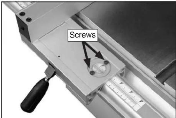
text_image
ScrewsFigure 69. Fence scale window and screws.
- Re-tighten the screws—the scale is now correctly calibrated.
SECTION 8: WIRING
These pages are current at the time of printing. However, in the spirit of improvement, we may make changes to the electrical systems of future machines. Compare the manufacture date of your machine to the one stated in this manual, and study this section carefully.
If there are differences between your machine and what is shown in this section, call Technical Support at (570) 546-9663 for assistance BEFORE making any changes to the wiring on your machine. An updated wiring diagram may be available. Note: Please gather the serial number and manufacture date of your machine before calling. This information can be found on the main machine label.
WARNING
Wiring Safety Instructions
SHOCK HAZARD. Working on wiring that is connected to a power source is extremely dangerous. Touching electrified parts will result in personal injury including but not limited to severe burns, electrocution, or death. Disconnect the power from the machine before servicing electrical components!
MODIFICATIONS. Modifying the wiring beyond what is shown in the diagram may lead to unpredictable results, including serious injury or fire. This includes the installation of unapproved aftermarket parts.
WIRE CONNECTIONS. All connections must be tight to prevent wires from loosening during machine operation. Double-check all wires disconnected or connected during any wiring task to ensure tight connections.
CIRCUIT REQUIREMENTS. You MUST follow the requirements at the beginning of this manual when connecting your machine to a power source.
WIRE/COMPONENT DAMAGE. Damaged wires or components increase the risk of serious personal injury, fire, or machine damage. If you notice that any wires or components are damaged while performing a wiring task, replace those wires or components.
MOTOR WIRING. The motor wiring shown in these diagrams is current at the time of printing but may not match your machine. If you find this to be the case, use the wiring diagram inside the motor junction box.
CAPACITORS/INVERTERS. Some capacitors and power inverters store an electrical charge for up to 10 minutes after being disconnected from the power source. To reduce the risk of being shocked, wait at least this long before working on capacitors.
EXPERIENCING DIFFICULTIES. If you are experiencing difficulties understanding the information included in this section, contact our Technical Support at (570) 546-9663.
NOTICE
The photos and diagrams included in this section are best viewed in color. You can view these pages in color at www.grizzly.com.
COLOR KEY


Wiring Diagram
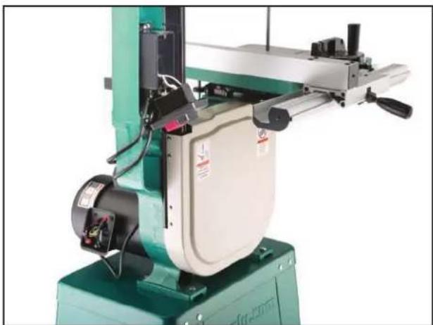
natural_image
Green industrial machine with mechanical components and a beige housing (no visible text or symbols)Figure 70. Motor and ON/OFF switch locations.
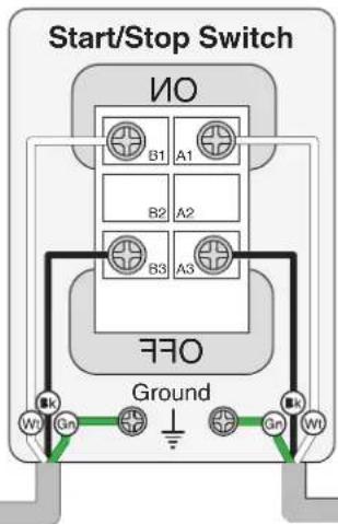
text_image
Start/Stop Switch NO B1 A1 B2 A2 B3 A3 FFO Ground Wt Gn Gn Wt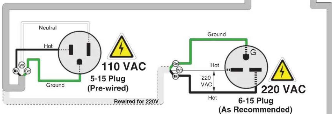
text_image
Neutral Hot 110 VAC 5-15 Plug (Pre-wired) Ground Rewired for 220V Ground G 220 VAC Hot 220 VAC 6-15 Plug (As Recommended)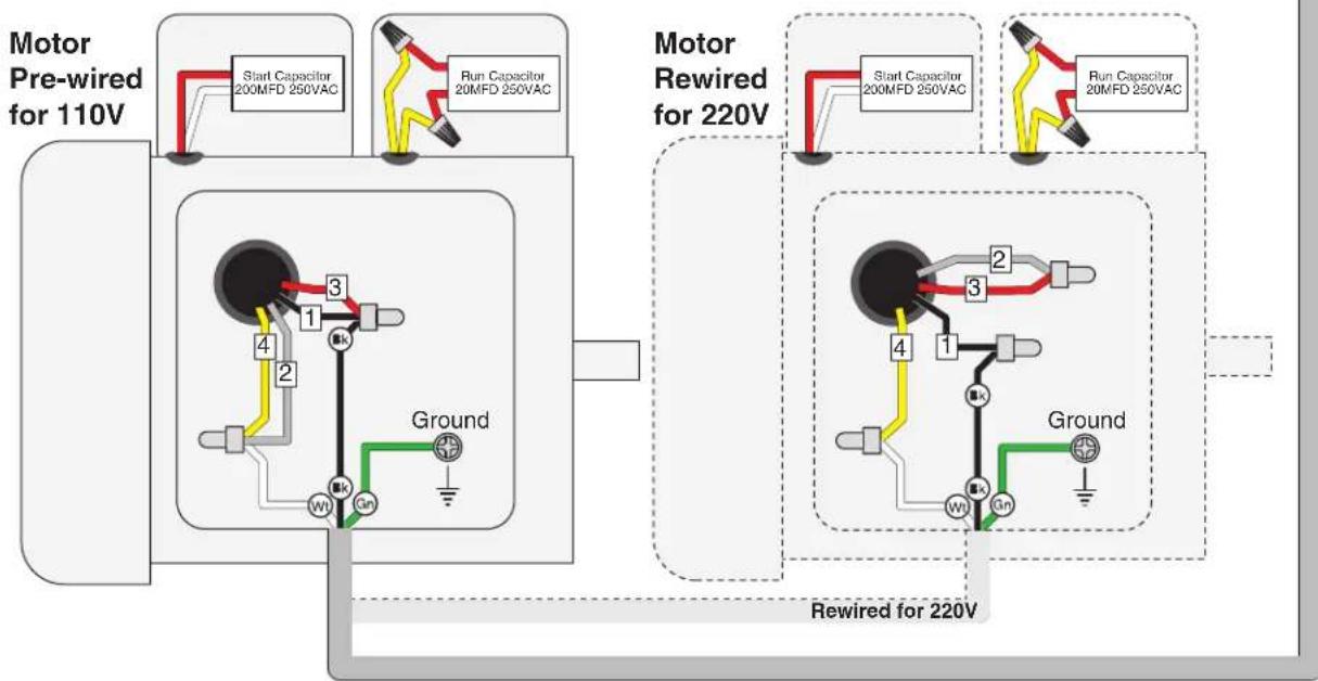
flowchart
graph TD
    A["Motor Pre-wired for 110V"] --> B["Start Capacitor 200MFD 250VAC"]
    A --> C["Run Capacitor 20MFD 250VAC"]
    D["Motor Rewired for 220V"] --> E["Start Capacitor 200MFD 250VAC"]
    D --> F["Run Capacitor 20MFD 250VAC"]
    G["Ground"] --> H["Ground"]
    I["Rewired for 220V"] --> J["Ground"]
    K["Ground"] --> L["Ground"]
SECTION 9: PARTS
Main
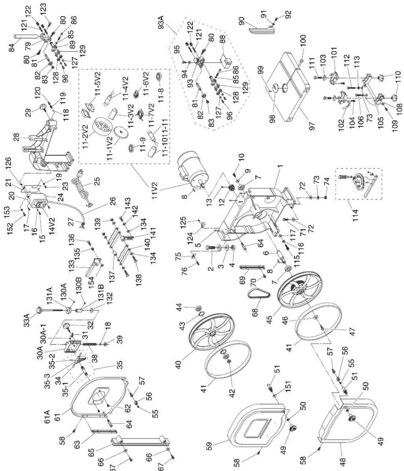
text_image
Technical diagram of a mechanical assembly with numbered components and exploded views, likely for assembly or manufacturing purposes.Main Parts List
REF PART # DESCRIPTION REF PART # DESCRIPTION
| 1 P0555001 BASE (G555) 45 P0555045 LOWER WHEEL ASSY W/TIRE | |||
| 1 P0555P001 BASE (G0555P) 46 P0555046 SHAFT WASHER 30 X 8 X 3MM | |||
| 2 P0555002 HEX BOLT M16-2 X 55 | 47 P05550 | ||
| 3 P0555003 FLAT WASHER 16MM | 48 P05550 | ||
| 4 P0555004 HEX NUT M16-2 | 48 P0555P | ||
| 5 P0555005 ALIGNMENT PIN | 49 P05550 | ||
| 6 P0555006 LOWER WHEEL SHAFT | 50 P05550 | ||
| 7 P0555007 BALL BEARING 6204 LLU | 51 P05550 | ||
| 8 P0555008 KEY 5 X 5 X 2$ | 55 P05550 | ||
| 9 P0555009 SHAFT WASHER 30 X 8 X 3MM | 56 P05550 | ||
| 10 | P0555010 | PHLP HD SCR M8-1.25 X 16 | |
| 11V2 | P0555011V2 | MOTOR 1HP 110/220V 60HZ V2.05.11 | |
| 11V2-1 | P0555011V2-1 | MOTOR FAN | |
| 11V2-2 | P0555011V2-2 | MOTOR FAN COVER | |
| 11V2-3 | P0555011V2-3 | S CAPACITOR COVER | |
| 11V2-4 | P0555011V2-4 | S CAPACITOR 200M 250V | |
| 11V2-5 | P0555011V2-5 | JUNCTION BOX | |
| 11V2-6 | P0555011V2-6 | CENTRIFUGAL SWITCH | |
| 11V2-7 | P0555011V2-7 | CONTACT PLATE | |
| 11V2-8 | P0555011V2-8 | BALL BEARING 6202ZZ | |
| 11V2-9 | P0555011V2-9 | BALL BEARING 6205ZZ | |
| 11V2-10 | P0555011V2-10 | R CAPACITOR COVER | |
| 11V2-11 | P0555011V2-11 | R CAPACITOR 20M 250V | |
| 12 | P0555012 MOTOR PULLEY | 69 | |
| 13 | P0555013 SET S CREW M6-1 X 12 | 70 | |
| 14V2 | P0555014V2 | ON/OFF SWITCH 110/220V V2.05.11 | |
| 15 | P0555015 TAP S CREW M3.5 X 12 | 72 | |
| 16 | P0555016 FLAT WASHER 4MM | 73 | |
| 17 | P0555017 PHLP HD SCR M5-.8 X 16 | 74 | |
| 18 | P0555018 TENS ON INDICATOR | 75 | |
| 19 | P0555019 | EXT TOOTH WASHER 5MM | |
| 20 | P0555020 SWITCH BOX | 79 | |
| 21 | P0555021 SWITCH BOX MOUNT | 80 | |
| 23 | P0555023 PHLP HD SCR M5-.8 X 6 | 81 | |
| 24 | P0555024 STRA N RELIEF | 82 | |
| 25 | P0555025 | POWER CORD 16G 3C 6FT 5-15 | |
| 26 | P0555026 MOTOR CORD | 84 | |
| 27 | P0555027 STRA N RELIEF | 85 | |
| 28 | P0555028 | UPPER FRAME ARM (G0555) | |
| 28 | P0555P028 | UPPER FRAME ARM (G0555P) | |
| 29 | P0555029 KNOB BOLT M10-1.5 X 30 | 89 | |
| 30A | P0555030A UPPER WHEEL SLIDING BRACKET V2.07.07 90 P0555 | ||
| 30A-1 | P0555030A-1 | SET SCREW M5-.8 X 8 | |
| 31 | P0555031 WING NUT M8-1.25 | 92 | |
| 32 | P0555032 KNOB BOLT M8-1.25 X 45 | 93 | |
| 33A | P0555033A | BLADE ADJ SCR ASSY 7" THREAD | |
| 34 | P0555034 DOWEL PIN | 95 | |
| 35 | P0555035 | UPPER WHEEL SHAFT HINGE ASSY | |
| 35-1 | P0555035-1 | UPPER WHEEL SHAFT | |
| 35-2 | P0555035-2 | ROLL PIN 3 X 6 | |
| 35-3 | P0555035-3 | UPPER WHEEL SHAFT HINGE | |
| 38 | P0555038 | COMPRESSION SPRING 3.8 X 13.5 X 81 | |
| 39 | P0555039 | SQUARE NUT M10-1.5 | |
| 40 | P0555040 UPPER WHEEL 102 P0555102 SCALE | ||
| 41 | P0555041 | WHEEL TIRE 14" | |
| 42 | P0555042 | HEX NUT M12-1.25 | |
| 43 | P0555043 | INT RETAINING RING 35MM | |
| 44 | P0555044 BALL BEARING 6202 LLU | ||
| HEX BOLT M8-1.25 X 20 LH | ||
| LOWER WHEEL COVER (G0555) | ||
| LOWER WHEEL COVER (G0555P) | ||
| NOB M8-1.25 | ||
| NT TOOTH WASHER 8MM | ||
| DOOR LATCH STUD M8-1.25 X 14 | ||
| PHLP HD SCR M5-.8 X 12 | ||
| CATCH | ||
| 57 | P0555057 | ALIGNMENT BOLT M5-.8 X 27 |
| 58 | P0555058 | TAP SCREW M4 X 8 |
| 59 | P0555059 | FRONT UPPER WHEEL COVER (G0555) |
| 59 | P0555P059 | FRONT UPPER WHEEL COVER (G0555P) |
| 61A | P0555061A | REAR UPPER WHEEL COVER V2.07.07 (G0555) |
| 61 | P0555P061 | REAR UPPER WHEEL COVER (G0555P) |
| 62 | P0555062 | FLANGE SCREW M5-.8 X 8 |
| 63 | P0555063 | UPPER WHEEL COVER HINGE |
| 64 | P0555064 | WHEEL COVER STANDOFF |
| 65 | P0555065 | LEFT BLADE GUARD |
| 66 | P0555066 | SPECIAL FLANGE WASHER 4MM |
| 67 | P0555067 | TAP SCREW M3.5 X 16 |
| 68 | P0555068 | RIBBED V-BELT 200J5 |
| 55069 | LOWER WHEEL COVER HINGE | |
| 55070 | FLAT HD SCR M5-.8 X 10 | |
| 71 | P0555071 | HEX BOLT M8-1.25 X 35 |
| 55072 | FLAT WASHER 8MM | |
| 55073 | LOCK WASHER 8MM | |
| 55074 | HEX NUT M8-1.25 | |
| 55075 | CORD CLAMP | |
| 76 | P0555076 | PHLP HD SCR M5-.8 X 12 |
| 55079 | GUIDE POST BRACKET | |
| 55080 | THUMB SCREW M6-1 X 16 | |
| 55081 | GUIDE SPACING SLEEVE | |
| 55082 | BALL BEARING 6000ZZ | |
| 83 | P0555083 | FLANGE SCREW M6-1 X 8 |
| 55084 | GUIDE POST | |
| 55085 | LOCK WASHER 5MM | |
| 86 | P0555086 | CAP SCREW M5-.8 X 40 |
| 88 | P0555088 | LOWER RIGHT BLADE GUARD |
| 55089 | UPPER GUIDE BRACKET | |
| UPPER RIGHT BLADE GUARD | ||
| 91 | P0555091 | FLAT WASHER 6MM |
| 55092 | HEX BOLT M6-1 X 8 | |
| 55093 | LOWER GUIDE BRACKET | |
| 94 | P0555094 | FLAT WASHER 6MM |
| 55095 | HEX BOLT M6-1 X 20 | |
| 96 | P0555096 | CAP SCREW M5-.8 X 12 |
| 97 | P0555097 | TABLE |
| 98 | P0555098 | TABLE INSERT |
| 99 | P0555099 | ROLL PIN 3 X 8 |
| 100 | P0555100 | TABLE PIN |
| 101 | P0555101 | TRUNNION |
| 103 | P0555103 | TRUNNION CLAMP SHOE |
| 104 | P0555104 | HEX BOLT M6-1 X 12 |
| 105 | P0555105 | TRUNNION SUPPORT BRACKET |
Main Parts List
REF PART # DESCRIPTION REF PART # DESCRIPTION
| 106 P0555106 HEX BOLT M8-1.25 X 30 129 P0555129 ECCENTRIC SHAFT | |
| 108 P0555108 POINTER 130A P0555130A SET SCREW M5-.8 X 8 | |
| 109 P0555109 FLANGE SCREW M5-.8 X 6 130B P0555130B SET SCREW M5-.8 X 5 | |
| 110 P0555110 KNOB M10-1.5 131A P0555131A UPPER LOCK COLLAR | |
| 111 P0555111 HEX BOLT M10-1.5 X 50 131B P0555131B LOWER LOCK COLLAR | |
| 112 P0555112 HEX BOLT M8-1.25 X 80 132 P0555132 FLAT WASHER 10MM | |
| 113 P0555113 HEX NUT M8-1.25 133 P0555133 QUICK RELEASE LEVER | |
| 114 P0555114 MITER GAUGE ASSEMBLY 134 P0555134 FLAT WASHER 8MM | |
| 115 P0555115 CAP SCREW M8-1.25 X 25 135 P0555135 BUSHING | |
| 116 P0555116 LOCK WASHER 8MM 136 P0555136 CAP SCREW M6-1 X 16 | |
| 117 P0555117 FLAT WASHER 8MM 137 P0555137 SPACER | |
| 118 P0555118 STEEL BALL 138 P0555138 HEX BOLT M8-1.25 X 40 | |
| 119 P0555119 COMPRESSION SPRING 1.5 X 5 X 9 139 P0555139 LOCK NUT M8-1.25 | |
| 120 P0555120 SET SCREW M10-1.5 X 10 140 P0555140 SUPPORT PLATE | |
| 121 P0555121 SET SCREW M8-1 X 35 141 P0555141 PIVOT ARM | |
| 122 P0555122 MICRO ADJUSTING NUT 1.65 142 P0555142 LOCK WASHER 8MM | |
| 123 P0555123 HEX BOLT M6-1 X 20 143 P0555143 HEX BOLT M8-1.25 X 20 | |
| 124 P0555124 CORD CLAMP 151 P0555151 FLAT WASHER 8MM | |
| 125 P0555125 PHLP HD SCR M5-.8 X 12 152 P0555152 PHLP HD SCR M5-.8 X 12 | |
| 126 P0555126 LOCK NUT M4-.7 153 P0555153 EXT TOOTH WASHER 5MM | |
| 127 P0555127 FLAT WASHER 5MM 154 P0555154 SPACER 8MM | |
| 128 P0555128 BALL BEARING 608ZZ |
Stand

text_image
201 202 204 205 206 207 208 211 212 grizzly.com 209 210 211 212 213REF PART # DESCRIPTION REF PART # DESCRIPTION
| 201 P0555201 STAND | TOP (G0555) 208 P0555208 FLANGE NUT | M6-1 | ||
| 201 P0555P201 STAND | TOP (G0555P) 209 P0555209 UPPER STAND BRACE (G0555) | |||
| 202 P0555202 CARRIAGE BOLT M8-1.25 X 16 209 P0555P209 UPPER STAND BRACE (G0555P) | ||||
| 204 P0555204 FLANGE NUT M8-1.25 210 P0555210 LOWER STAND BRACE (G0555) | ||||
| 205 P0555205 STAND | SIDE (G0555) 210 P0555P210 LOWER STAND BRACE (G0555P) | |||
| 205 P0555P205 STAND | SIDE (G0555P) 211 P0555211 HEX NUT 3/8-16 | |||
| 206 P0555206 HEX BOLT M6-1 X 16 | 212 P0555212 FLAT WASHER 10MM | |||
| 207 P0555207 FLAT WASHER 6MM | 213 P0555213 STAND FOOT | |||
Fence
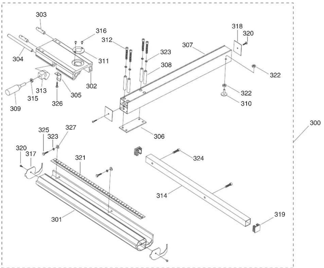
text_image
Technical diagram of a mechanical assembly with numbered components and labeled partsREF PART # DESCRIPTION REF PART # DESCRIPTION
| 300 P0555300 FENCE | KIT ASSEMBLY W/RAILS 314 P0555314 REAR FENCE RAIL | |||
| 301 P0555301 FRONT | FENCE RAIL 315 P0555315 HEX NUT M6-1 | |||
| 302 P0555302 FENCE | BASE 316 P0555316 FLANGE SCREW M4-.7 X 6 | |||
| 303 P0555303 FENCE | MOUNT ROD 317 P0555317 FRONT RAIL END CAP | |||
| 304 P0555304 LOCK S HAFT 318 P0555318 FENCE END CAP | ||||
| 305 P0555305 SPRING PLATE 319 P0555319 REAR RAIL END CAP | ||||
| 306 P0555306 SPACER PLATE 320 P0555320 TAP SCREW M3.5 X 8 | ||||
| 307 P0555307 FENCE | 321 | P0555321 | SCALE | |
| 308 P0555308 SLEEVE | 322 | P0555322 | HEX NUT M6-1 | |
| 309 P0555309 LOCK H ANDLE | 323 | P0555323 | LOCK WASHER | 6MM |
| 310 P0555310 FENCE STAND-OFF | 324 | P0555324 | CAP SCREW M6-1 X 16 | |
| 311 P0555311 SCALE WINDOW | 325 | P0555325 | HEX BOLT M6-1 | X 20 |
| 312 P0555312 CAP SC REW M6-1 X 60 | 326 | P0555326 | FLANGE SCREW M4-.7 X 8 | |
| 313 P0555313 LOCK Q AM | 327 | P0555327 | FLAT WASHER | 6MM |
Labels
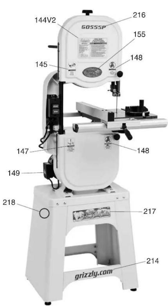
text_image
144V2 GOS5SP 216 155 148 145 147 148 149 218 217 214 grizzly.com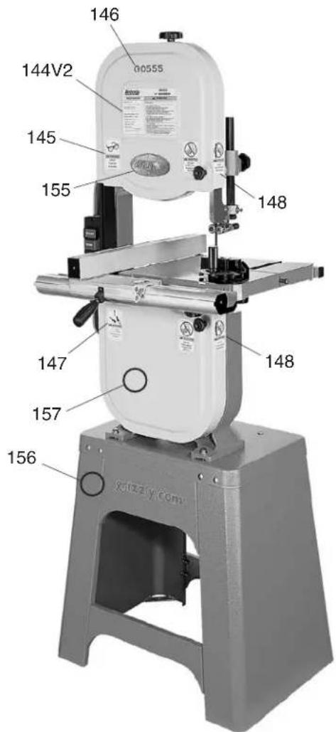
text_image
146 144V2 145 155 148 147 157 156 G0555REF PART # DESCRIPTION REF PART # DESCRIPTION
| 144V2 | P0555144V2 | MACHINE ID LABEL V2.05.11 (G0555) 155 P0555155 | GRIZZLY | NAMEPLATE | |
| 144V2 | P0555P144V2 | MACHINE ID LABEL V2.05.11 (G0555P) 156 P0555156 | GRIZZLY | GREEN TOUCH-UP PAINT | |
| 145 P05 | 55145 SAFETY | GLASSES LABEL 157 P0555157 GRIZZLY PUTTY TOUCH | TOUCH | UP PAINT | |
| 146 P05 | 55146 MODEL | NUMBER LABEL (G0555) 214 P0555P214 | GRIZZLY.COM | LABEL (G0555P) | |
| 147 | P0555147 | UNPLUG BANDSAW LABEL | 216 | P0555P216 | MODEL NUMBER LABEL (G0555P) |
| 148 P05 | 55148 BANDSAW | DOOR LABEL 217 P0555P217 | POLAR BEAR LOGO | ||
| 149 | P0555149 | ELECTRICITY LABEL | 218 | P0555P218 | POLAR BEAR WHITE TOUCH-UP PAINT |
WARNING
Safety labels help reduce the risk of serious injury caused by machine hazards. If any label comes off or becomes unreadable, the owner of this machine MUST replace it in the original location before resuming operations. For replacements, contact (800) 523-4777 or www.grizzly.com.
WARRANTY CARD
Name
Street
City
State
Zip
Phone #
Model #
Order #
Serial #
The following information is given on a voluntary basis. It will be used for marketing purposes to help us develop better products and services. Of course, all information is strictly confidential.
- How did you learn about us?
Advertisement Friend Catalog Card Deck Website Other:
- Which of the following magazines do you subscribe to?
Cabinetmaker & FDM Family Handyman Hand Loader Handy Home Shop Machinist Journal of Light Cont. Live Steam Model Airplane News Old House Journal Popular Mechanics
Popular Science Popular Woodworking Precision Shooter Projects in Metal RC Modeler Rifle Shop Notes Shotgun News Today's Homeowner Wood
Wooden Boat Woodshop News Woodsmith Woodwork Woodworker West Woodworker's Journal Other:
- What is your annual household income?
____ \20,000-\29,000 ____ \30,000-\39,000 ____ \40,000-\49,000 ____ \50,000-\59,000 ____ \60,000-\69,000 ____ \$70,000+
- What is your age group?
____ 20-29 ____ 50-59 ____ 30-39 ____ 60-69 ____ 40-49 ____ 70+
- How long have you been a woodworker/metalworker?
0-2 Years
2-8 Years
8-20 Years
20+ Years
- How many of your machines or tools are Grizzly?
0-2
3-5
6-9
10+
- Do you think your machine represents a good value?
____ Yes
No
- Would you recommend Grizzly Industrial to a friend?
____ Yes
No
- Would you allow us to use your name as a reference for Grizzly customers in your area?
Note: We never use names more than 3 times. ____ Yes ____ No
- Comments:
FOLD ALONG DOTTED LINE

Place Stamp Here

text_image
Grizzly Industrial, Inc.GRIZZLY INDUSTRIAL, INC. P.O. BOX 2069 BELLINGHAM, WA 98227-2069
-
-
-
-
-
-
-
-
-
-
-
-
-
-
-
-
-
-
-
-
-
-
-
-
-
-
-
-
-
-
-
-
-
-
-
-
-
-
-
-
-
-
-
-
-
-
-
-
-
-
-
-
-
-
-
-
-
-
-
-
-
-
-
-
-
-
-
-
-
-
-
-
-
-
-
-
-
-
-
-
-
-
-
-
-
-
-
-
-
-
-
-
-
-
-
-
-
- 99.
-
-
-
-
-
-
-
-
-
-
-
-
-
-
-
-
-
-
-
-
-
-
-
-
-
-
-
-
-
-
-
-
-
-
-
-
-
-
-
-
-
-
-
-
-
-
-
-
-
-
-
-
-
-
-
-
-
-
-
-
-
-
-
-
-
-
-
-
-
-
-
-
-
-
-
-
-
-
-
-
-
-
-
-
-
-
-
-
-
-
-
-
-
-
-
-
FOLD ALONG DOTTED LINE
Send a Grizzly Catalog to a friend:
Name____
Street
City____State____Zip____
TAPE ALONG EDGES--PLEASE DO NOT STAPLE
WARRANTY AND RETURNS
Grizzly Industrial, Inc. warrants every product it sells for a period of 1 year to the original purchaser from the date of purchase. This warranty does not apply to defects due directly or indirectly to misuse, abuse, negligence, accidents, repairs or alterations or lack of maintenance. This is Grizzly's sole written warranty and any and all warranties that may be implied by law, including any merchantability or fitness, for any particular purpose, are hereby limited to the duration of this written warranty. We do not warrant or represent that the merchandise complies with the provisions of any law or acts unless the manufacturer so warrants. In no event shall Grizzly's liability under this warranty exceed the purchase price paid for the product and any legal actions brought against Grizzly shall be tried in the State of Washington, County of Whatcom.
We shall in no event be liable for death, injuries to persons or property or for incidental, contingent, special, or consequential damages arising from the use of our products.
To take advantage of this warranty, contact us by mail or phone and give us all the details. We will then issue you a “Return Number,” which must be clearly posted on the outside as well as the inside of the carton. We will not accept any item back without this number. Proof of purchase must accompany the merchandise.
The manufacturers reserve the right to change specifications at any time because they constantly strive to achieve better quality equipment. We make every effort to ensure that our products meet high quality and durability standards and we hope you never need to use this warranty.
Please feel free to write or call us if you have any questions about the machine or the manual.
Thank you again for your business and continued support. We hope to serve you again soon.
Buy Direct and Save with Grizzly® – Trusted, Proven and a Great Value! \~Since 1983\~
Visit Our Website Today For Current Specials!
ORDER 24 HOURS A DAY! 1-800-523-4777