
C 14DMR - Saw HITACHI - Free user manual and instructions
Find the device manual for free C 14DMR HITACHI in PDF.


| Product Type | Cut-off saw |
| Brand | Hitachi |
| Model | C 14DMR |
| Blade diameter | 355 mm (14 inches) |
| Blade arbor | 25.4 mm (1 inch) |
| Power consumption | 2,000 W |
| No-load speed | 3,800 rpm |
| Max. cutting depth | 125 mm |
| Dimensions (L x W x H) | 500 x 300 x 400 mm |
| Weight | 15 kg |
| Power supply | Single-phase 230 V / 50 Hz |
| Arbor lock function | Yes |
| Overload protection | Integrated thermal circuit breaker |
| Safety switch | Trigger switch with lock |
| Maintenance and cleaning | Clean ventilation slots and cutting area after each use; replace motor brushes if necessary |
| Spare parts and repairability | Blade, brushes, switch, power cable – available at authorized dealers |
| Warranty | 2 years (except professional use) |
Frequently Asked Questions - C 14DMR HITACHI
User questions about C 14DMR HITACHI
0 question about this device. Answer the ones you know or ask your own.
Ask a new question about this device
Download the instructions for your Saw in PDF format for free! Find your manual C 14DMR - HITACHI and take your electronic device back in hand. On this page are published all the documents necessary for the use of your device. C 14DMR by HITACHI.
USER MANUAL C 14DMR HITACHI
natural_image
Technical line drawing of a mechanical device with cutaway view (no text or symbols)SAFETY INSTRUCTIONS AND INSTRUCTION MANUAL
WARNING
IMPROPER OR UNSAFE use of this power tool can result in death or serious bodily injury!
This manual contains important information about product safety. Please read and understand this manual BEFORE operating the power tool. Please keep this manual available for other users and owners before they use the power tool. This manual should be stored in safe place.
INSTRUCTIONS DE SECURITE ET MODE D'EMPLOI
! AVERTISSEMENT
IMPORTANT SAFETY INFORMATION .... 3
MEANINGS OF SIGNAL WORDS .... 3
SAFETY 4
GENERAL SAFETY RULES – FOR ALL BATTERY OPERATED TOOLS 4
SPECIFIC SAFETY RULES 6
IMPORTANT SAFETY INSTRUCTIONS FOR USE OF THE CORDLESS CIRCULAR SAW ...... 9
IMPORTANT SAFETY INSTRUCTIONS FOR BATTERY CHARGER 9
IMPORTANT SAFETY INSTRUCTIONS FOR USE OF THE BATTERY AND BATTERY CHARGER ...... 11
FUNCTIONAL DESCRIPTION 12
MODEL 12
NAME OF PARTS 12
SPECIFICATIONS 13
Page
ASSEMBLY AND OPERATION 14
APPLICATIONS 14
REMOVAL AND INSTALLATION METHOD OF BATTERY 14
CHARGING METHOD 14
BEFORE USE 21
ADJUSTING THE SAW PRIOR TO USE 22
OPERATION 23
MOUNTING AND DISMOUNTING THE SAW BLADE....26
REPLACING LIGHT BULB (ONLY MODEL WITH LIGHT) 27
MAINTENANCE AND INSPECTION 29
ACCESSORIES 31
STANDARD ACCESSORIES 31
OPTIONAL ACCESSORIES 32
PART LIST 98
TABLE DES MATIERES
Français
Page
INFORMATIONS IMPORTANTES DE SÉCURITÉ ...33
SIGNIFICATION DES MOTS D'AVERTISSEMENT ...33
SECURITE 34
REGLES GENERALE DE SECURITE – POUR TOUS LES OUTILS FONCTIONNANT SUR BATTERIE .....34
REGLES DE SECURITE SPECIFIQUES ...... 36
CONSIGNES DE SÉCURITÉ IMPORTANTES POUR L'UTILISATION DU SCIE CIRCULAIRE SANS FIL ..... 40
CONSIGNES DE SÉCURITÉ IMPORTANTES POUR LE CHARGEUR DE BATTERIE ..... 41
CONSIGNES DE SÉCURITÉ IMPORTANTES POUR L'UTILISATION DE LA BATTERIE ET DU CHARGEUR DE BATTERIE ..... 42
DESCRIPTION FONCTIONNELLE 44
MODELE 44
NOM DES PARTIES 44
SPECIFICATIONS 45
Page
ASSEMBLAGE ET FONCTIONNEMENT .... 46
UTILISATIONS 46
MÉTHODE DE RETRAIT ET D'INSTALLATION DE LA BATTERIE 46
MÉTHODE DE RECHARGE 46
IMPORTANT SAFETY INFORMATION
Read and understand all of the safety precautions, warnings and operating instructions in the Instruction Manual before operating or maintaining this power tool.
Most accidents that result from power tool operation and maintenance are caused by the failure to observe basic safety rules or precautions. An accident can often be avoided by recognizing a potentially hazardous situation before it occurs, and by observing appropriate safety procedures.
Basic safety precautions are outlined in the “ SAFETY” section of this Instruction Manual and in the sections which contain the operation and maintenance instructions.
Hazards that must be avoided to prevent bodily injury or machine damage are identified by WARNINGS on the power tool and in this Instruction Manual.
NEVER use this power tool in a manner that has not been specifically recommended by HITACHI.
MEANINGS OF SIGNAL WORDS
WARNING indicates a potentially hazardous situations which, if ignored, could result in death or serious injury.
CAUTION indicates a potentially hazardous situations which, if not avoided, may result in minor or moderate injury, or may cause machine damage.
NOTE emphasizes essential information.
SAFETY
GENERAL SAFETY RULES – FOR ALL BATTERY OPERATED TOOLS

WARNING: Read and understand all instructions.
Failure to follow all instructions listed below, may result in electric shock, fire and/or serious personal injury.
SAVE THESE INSTRUCTIONS
1. Work Area
(1) Keep your work area clean and well lit. Cluttered benches and dark areas invite accidents.
(2) Do not operate power tools in explosive atmospheres, such as in the presence of flammable liquids, gases, or dust. Power tools create sparks which may ignite the dust of fumes.
(3) Keep bystanders, children, and visitors away while operating a power tool.
Distractions can cause you to lose control.
2. Electrical Safety
(1) A battery operated tool with integral batteries or a separate battery pack must be recharged only with the specified charger for the battery.
A charger that may be suitable for one type of battery may create a risk of fire when used with another battery.
(2) Use battery operated tool only with specifically designed battery pack.
Use of any other batteries may create a risk of fire.
3. Personal Safety
(1) Stay alert, watch what you are doing and use common sense when operating a power tool. Do not use tool while tired or under the influence of drugs, alcohol, or medication. A moment of inattention while operating power tools may result in serious personal injury.
(2) Dress properly. Do not wear loose clothing or jewelry. Contain long hair. Keep your hair, clothing, and gloves away from moving parts. Loose clothes, jewelry, or long hair can be caught in moving parts.
(3) Avoid accidental starting. Be sure switch is off position before inserting battery. Carrying tools with your finger on the switch or inserting the battery pack into a tool with the switch on invites accidents.
(4) Remove adjusting keys or wrenches before turning the tool on. A wrench or a key that is left attached to a rotating part of the tool may result in personal injury.
(5) Do not overreach. Keep proper footing and balance at all times. Proper footing and balance enables better control of the tool in unexpected situations.
(6) Use safety equipment. Always wear eye protection. Dust mask, non-skid safety shoes, hard hat, or hearing protection must be used for appropriate conditions.
4. Tool Use and Care
(1) Use clamps or other practical way to secure and support the workpiece to a stable platform. Holding the work by hand or against your body is unstable and may lead to loss of control.
(2) Do not force tool. Use the correct tool for your application. The correct tool will do the job better and safer at the rate for which it is designed.
(3) Do not use tool if switch does not turn it on or off. Any tool that cannot be controlled with the switch is dangerous and must be repaired.
(4) Disconnect battery pack from tool or place the switch in the locked or off position before making any adjustments, changing accessories, or storing the tools. Such preventive safety measures reduce the risk of starting the tool accidentally.
(5) Store idle tools out of reach of children and other untrained persons. Tools are dangerous in the hands of untrained users.
(6) When battery pack is not in use, keep it away from other metal objects like: paper clips, coins, keys, nails, screws, or other small metal objects that can make a connection from one terminal to another.
Shorting the battery terminals together may cause sparks, burns, or a fire.
(7) Maintain tools with care. Keep cutting tools sharp and clean. Properly maintained tools, with sharp cutting edges are less likely to bind and are easier to control.
(8) Check for misalignment or binding of moving parts, breakage of parts, and any other condition that may affect the tools operation. If damaged, have the tool serviced before using. Many accidents are caused by poorly maintained tools.
(9) Use only accessories that are recommended by the manufacturer for your model. Accessories that may be suitable for one tool may create a risk of injury when used on another tool.
5. Service
(1) Tool service must be performed only by qualified repair personnel. Service or maintenance performed by unqualified personnel could result in a risk of injury.
(2) When servicing a tool, use only identical replacement parts. Follow instructions in the Maintenance section of this manual. Use of unauthorized parts or failure to follow Maintenance Instruction may create a risk of electric shock or injury.
WARNING:
Some dust created by power sanding, sawing, grinding, drilling, and other construction activities contains chemicals known to the State of California to cause cancer, birth defects or other reproductive harm. Some examples of these chemicals are:
- Lead from lead-based paints,
- Crystalline silica from bricks and cement and other masonry products, and
- Arsenic and chromium from chemically-treated lumber.
Your risk from these exposures varies, depending on how often you do this type of work. To reduce your exposure to these chemicals: work in a well ventilated area, and work with approved safety equipment, such as those dust masks that are specially designed to filter out microscopic particles.
SPECIFIC SAFETY RULES
- DANGER! Keep hands away from cutting area and blade. Keep your second hand on auxiliary handle or motor housing. If both hands are holding the saw, they cannot be cut by the blade.
Keep your body positioned to either side of the saw blade, but not in line with the saw blade. KICKBACK could cause the saw to jump backwards. (See KICKBACK)
Do not reach underneath the work. The guard can not protect you from the blade below the work. - Check lower guard for proper closing before each use. Do not operate saw if lower guard does not move freely and close instantly. Never clamp or tie the lower guard into the open position. If saw is accidentally dropped, lower guard may be bent. Raise the lower guard with the Retracting Handle and make sure it moves freely and does not touch the blade or any other part, in all angles and depths of cut.
- Check the operation and condition of the lower guard spring. If the guard the spring are not operating properly, they must be serviced before use. Lower guard may operate sluggishly due to damaged parts, gummy deposits, or a buildup of debris.
- lower guard should be retracted manually only for special cuts such as “Pocket Cuts” and “Compound Cuts.” Raise lower guard by Retracting Handle. As soon as blade enters the material, lower guard must be released. For all other sawing, the lower guard should operate automatically.
- Always observe that the lower guard is covering the blade before placing saw down on bench or floor. An unprotected, coasting blade will cause the saw to walk backwards, cutting whatever is in its path. Be aware of the time it takes for the blade to stop after switch is released.
- NEVER hold piece being cut in your hands or across your leg. It is important to support the work properly to minimize body exposure, blade binding, or loss of control.
- Hold tool by insulated gripping surfaces when performing an operation where the cutting tool may contact hidden wiring. Contact with a "live" wire will also make exposed metal parts of the tool "live" and shock the operator.
- When ripping always use a rip fence or straight edge guide. This improves the accuracy of cut and reduces the chance for blade binding.
- Always use blades with correct size and shape (diamond vs. round) arbor holes. Blades that do not match the mounting hardware of the saw will run eccentrically, causing loss of control.
- Never use damaged or incorrect blade washers or bolts. The blade washers and bolt were specially designed for your saw, for optimum performance and safety of operation.
-
Causes and Operator Prevention of Kickback:
Kickback is a sudden reaction to a pinched, bound, or misaligned saw blade, causing an uncontrolled saw to lift up and out of the workpiece toward the operator.
When the blade is pinched or bound tightly by the kerf closing down, the blade stalls and the motor reaction drives the unit rapidly back toward the operator.
If the blade becomes twisted or misaligned in the cut, the teeth at the back edge of the blade can dig into the top surface of the wood causing the blade to climb out of the kerf and jump back toward the operator.
Kickback is the result of tool misuse and/or incorrect operating procedures or conditions and can be avoided by taking proper precautions as given below: -
Maintain a firm grip on the saw and position your body and arm in a way that allows you to resist KICKBACK forces. KICKBACK forces can be controlled by the operator, if proper precautions are taken.
- When blade is binding, or when interrupting a cut for any reason, release the trigger and hold the saw motionless in the material until the blade comes to a complete stop. Never attempt to remove the saw from the work or pull the saw backward while the blade is in motion or KICKBACK may occur. Investigate and take corrective actions to eliminate the cause of blade binding.
- When restarting a saw in the workpiece, center the saw blade in the kerf and check that teeth are not engaged into the material. If saw blade is binding, it may walk up or KICKBACK from the workpiece as the saw is restarted.
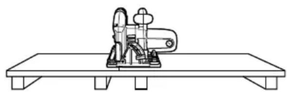
- Support large panels to minimize the risk of blade pinching and KICKBACK. Large panels tend to sag under their own weight. Supports must be placed under the panel on both sides, near the line of cut and near the edge of the panel as shown in Fig. 1.
To minimize the risk of blade pinching and kickback. When cutting operation requires the resting of the saw on the work piece, the saw shall be rested on the larger portion and the
smaller piece cut off.
natural_image
Line drawing of a mechanical device mounted on a flat base (no text or symbols)
natural_image
Line drawing of a table with a mechanical device and two chairs, crossed by two gray X-shaped markers (no text or symbols)To avoid kickback, do support board Don't support board or panel away or panel near the cut. from the cut.
Fig. 1 Fig. 2
-
Do not use dull or damaged blade. Unsharpened or improperly set blades produce narrow kerf causing excessive friction, blade binding, and KICKBACK.
-
Blade depth and bevel adjusting locking levers must be tight and secure before making cut. If blade adjustment shifts while cutting, it will cause binding and KICKBACK.
-
Use extra caution when making a “Pocket Cut” into existing walls or other blind areas. The protruding blade may cut objects that can cause KICKBACK.
-
Hold tools by insulated gripping surfaces when performing an operation where the cutting tool may contact hidden wiring or its own cord. Contact with a “live” wire will make exposed metal parts of the tool “live” and shock the operator.
-
Never touch moving parts.
Never place your hands, fingers or other body parts near the tool's moving parts.
- Never operate without all guards in place.
Never operate this tool without all guards or safety features in place and in proper working order. If maintenance or servicing requires the removal of a guard or safety feature, be sure to replace the guard or safety feature before resuming operation of the tool.
22. Use right tool.
Don't force small tool or attachment to do the job of a heavy-duty tool.
Don't use tool for purpose not intended—for example—don't use circular saw for cutting tree limbs or logs.
23. Never use a power tool for applications other than those specified.
Never use a power tool for applications other than those specified in the Instruction Manual.
24. Handle tool correctly.
Operate the tool according to the instructions provided herein. Do not drop or throw the tool. Never allow the tool to be operated by children, individuals unfamiliar with its operation or unauthorized personnel.
25. Definitions for symbols.
V ..... volts
==......direct current
n。…… no load speed
---/min ...... revolutions or reciprocation per minute
26. Keep all screws, bolts and covers tightly in place.
Keep all screws, bolts, and plates tightly mounted. Check their condition periodically.
27. Do not use power tools if the plastic housing or handle is cracked.
Cracks in the tool's housing or handle can lead to electric shock. Such tools should not be used until repaired.
28. Blades and accessories must be securely mounted to the tool.
Prevent potential injuries to yourself or others. Blades, cutting implements and accessories which have been mounted to the tool should be secure and tight.
29. Never use a tool which is defective or operating abnormally.
If the tool appears to be operating unusually, making strange noises, or otherwise appears defective, stop using it immediately and arrange for repairs by a Hitachi authorized service center.
30. Carefully handle power tools.
Should a power tool be dropped or struck against hard materials inadvertently, it may be deformed, cracked, or damaged.
31. Do not wipe plastic parts with solvent.
Solvents such as gasoline, thinner benzine, carbon tetrachloride, and alcohol may damage and crack plastic parts. Do not wipe them with such solvents.
Wipe plastic parts with a soft cloth lightly dampened with soapy water and dried thoroughly.
IMPORTANT SAFETY INSTRUCTIONS FOR USE OF THE CORDLESS CIRCULAR SAW

WARNING: Death or serious bodily injury could result from improper or unsafe use of the cordless circular saw. To avoid these risks, follow these basic safety instructions:
- Wear ear plugs when using the tool for extended periods. Prolonged exposure to high intensity noise can cause hearing loss.
- Never wedge or tie lower guard open. Check operation of lower guard before each use. Do not use if lower guard does not close briskly over saw blade.

CAUTION: If saw is dropped, safety cover may be bent restricting full return.
- For this mode, the saw blades range should be from 165 mm to 160 mm.
- Never place hands or other body parts near the saw blade during operation. Hold the circular saw by its handle only.
- Because the cordless circular saw operates by battery power, be aware of the fact that it can begin to operate at any time.
- Wear eye and ear protection at all times.
- When working at elevated locations, clear the area of other people and aware of conditions below you.
- It is important to support the work properly and to hold the saw firmly to prevent loss of control which could cause personal injury.
-
Guard against kickback: Kickback occurs when the saw stalls rapidly and is driven back towards the operator. Release switch immediately if blade binds or saw stalls.
-
Keep blades sharp.
- Support the panel near the cut.
- Use guide when ripping.
- Don't force tool.
- Stay alert exercise control
-
Don't remove saw from work during a cut while the blade is moving.
-
In operating, keep hold main body firmly.
-
Keep the light ON during cutting operation only. If it is lit ON in other cases, the main body switch can be inadvertently turned ON, resulting in unexpected accidents.
IMPORTANT SAFETY INSTRUCTIONS FOR BATTERY CHARGER
- This manual contains important safety and operating instructions for battery charger Model UC24YFA/UC24YJ/UC18YG.
- Before using battery charger, read all instructions and cautionary markings on (1) battery charger, (2) battery, and (3) product using battery.
-
To reduce risk of injury, charge HITACHI rechargeable battery type EB7, EB9, EB12, EB14, EB18, EB24 series. Other type of batteries may burst causing personal injury and damage.
-
Do not expose battery charger to rain or snow.
- Use of an attachment not recommended or sold by the battery charger manufacturer may result in a risk of fire, electric shock, or injury to persons.
- To reduce risk of damage to electric plug and cord, pull by plug when disconnecting battery charger.
- Make sure cord is located so that it will not be stepped on, tripped over, or otherwise subjected to damage or stress.
- An extension cord should not be used unless absolutely necessary. Use of improper extension cord could result in a risk of fire and electric shock.
If extension cord must be used make sure:
a. That blades of extension cord are the same number, size, and shape as those of plug on battery charger:
b. That extension cord is properly wired and in good electrical condition; and
c. That wire size is large enough for AC ampere rating of battery charger as specified in Table 1.
Table 1 RECOMMENDED MINIMUM AWG SIZE FOR EXTENSION CORDS FOR BATTERY CHARGERS
| AC Input Rating Amperes* AWG Size of Cord | |||||
| Equal to or but less Length of Cord, Feet (Meter) greater than than 25 (7.5) 50 (15) 100 (30) 150 (45) | |||||
| 0 | 2 | 18 | 18 | 18 | 16 |
| 2 | 3 | 18 | 18 | 16 | 14 |
| 3 | 4 | 18 | 18 | 16 | 14 |
* If the input rating of a battery charger is given in watts rather than in amperes, the corresponding ampere rating is to be determined by dividing the wattage rating by the voltage rating—for example:
$$ \frac {1 , 2 5 0 \text { watts }}{1 2 5 \text { volts }} = 1 0 \text { amperes } $$
- Do not operate battery charger with damaged cord or plug-replace them immediately.
- Do not operate battery charger if it has received a sharp blow, been dropped, or otherwise damaged in any way; take it to a qualified serviceman.
- Do not disassemble battery charger; take it to a qualified serviceman when service or repair is required. Incorrect reassembly may result in a risk of electric shock or fire.
- To reduce risk of electric shock, unplug charger from receptacle before attempting any maintenance or cleaning. Removing the battery will not reduce this risk.
IMPORTANT SAFETY INSTRUCTIONS FOR USE OF THE BATTERY AND BATTERY CHARGER
You must charge the battery before you can use the cordless circular saw. Before using the model UC24YFA/UC24YJ/UC18YG battery charger, be sure to read all instructions and cautionary statements on it, the battery and in this manual.
REMEMBER: USE ONLY HITACHI BATTERY TYPES EB7 SERIES, EB9 SERIES, EB12 SERIES, EB14 SERIES, EB18 SERIES, EB24 SERIES. OTHER TYPES OF BATTERIES MAY BURST AND CAUSE INJURY!
Follow these instructions to avoid the risk of injury:

WARNING: Improper use of the battery or battery charger can lead to serious injury. To avoid these injuries:
- NEVER disassemble the battery.
- NEVER incinerate the battery, even if it is damaged or is completely worn out. The battery can explode in a fire.
- NEVER short-circuit the battery.
- NEVER insert any objects into the battery charger's air vents. Electric shock or damage to the battery charger may result.
- NEVER charge outdoors. Keep the battery away from direct sunlight and use only where there is low humidity and good ventilation.
- NEVER charge when the temperature is below 32^ F ( 0^ C) or above 104^ F ( 40^ C).
- NEVER connect two battery chargers together.
- NEVER insert foreign objects into the hole for the battery or the battery charger.
- NEVER use a booster transformer when charging.
- NEVER use an engine generator or DC power to charge.
- NEVER store the battery or battery charger in places where the temperature may reach or exceed 104^ F ( 40^ C).
- ALWAYS operate charger on standard household electrical power (120 volts). Using the charger on any other voltage may overheat and damage the charger.
- ALWAYS wait at least 15 minutes between charges to avoid overheating the charger.
- ALWAYS disconnect the power cord from its receptacle when the charger is not in use.
SAVE THESE INSTRUCTIONS
AND
MAKE THEM AVAILABLE TO
OTHER USERS
AND
OWNERS OF THIS TOOL!
FUNCTIONAL DESCRIPTION
NOTE: The information contained in this Instruction Manual is designed to assist you in the safe operation and maintenance of the power tool.
NEVER operate, or attempt any maintenance on the tool unless you have first read and understood all safety instructions contained in this manual.
Some illustrations in this Instruction Manual may show details or attachments that differ from those on your own power tool
MODEL
C14DMR: with charger and case
NAME OF PARTS
- Cordless Circular Saw (C14DMR)

○Battery (EB1414S)

Fig. 3
2. Battery Charger

Fig. 4
SPECIFICATIONS
1. Cordless Circular Saw (C14DMR)
| Motor DC motor | ||
| No-load speed 3,100/min | ||
| Max. Cutting Depth 2-1/4" (57 mm) | ||
| Blade Size | 6-1/2" (165 mm) D × 5/8" (15.9 mm) H × 1/16" (1.6 mm) T | |
| Battery | Model | EB1414S |
| Type | Nickel cadmium battery | |
| Voltage DC 14.4V | ||
| Charging & discharging frequency | UC24YFA/UC24YJ ....about 1,000 times | |
| UC18YG ....about 300 times | ||
| Light Bulb 12V, 5W | ||
| Weight 7.1 lbs. (3.2 kg) | ||
2. Battery Charger
| Model UC24YFA UC24YJ | UC18YG | |||||
| Input power source Single phase: AC120V 60Hz | ||||||
| Charging time (At a temperature) of 68°F (20°C) | EB1414S | Approx. 40 min. | Approx. 10 min. | Approx. 30 min. | ||
| Charging voltage | DC 7.2 – 24V | DC 7.2 – 14.4V | DC 18V | DC 24V | DC 7.2 – 18V | |
| Charging current | DC 2.5A | DC 9A | DC 7.5A | DC 6A | DC 2.6A | |
| Weight 1.3 lbs. (0.6 kg) | 2.2 lbs. (1 kg) | 0.7 lbs. (0.3 kg) | ||||
NOTE: The charging time may vary according to ambient temperature and power source voltage.
ASSEMBLY AND OPERATION
APPLICATIONS
○Cutting Various types of wood.
REMOVAL AND INSTALLATION METHOD OF BATTERY

Fig. 5
○How to install the battery.
Align the battery with the groove in tool handle and install it into place.
Always insert it all the way until it locks in place with a little click, If not, it may accidentally fall out of the tool, causing injury to you or someone around you (Fig. 5).
○How to remove the battery.
Withdraw battery from the tool handle while pressing the latches on both sides of the battery (Fig. 5).
CHARGING METHOD
NOTE: Before plugging into the receptacle, make sure the following points.
○The power source voltage is stated on the nameplate.
○The cord is not damaged.

WARNING: Do not charge at voltage higher than indicated on the nameplate.
If charged at voltage higher than indicated on the nameplate, the charger will burn out.

Fig. 6
- Insert the plug of battery charger into the receptacle
When the plug of battery charger has been inserted into the receptacle, pilot lamp will blink in red. (At 1-second intervals)

natural_image
Black and white illustration of a hand with a lightning bolt symbol (no text or numbers)WARNING: Do not use the electrical cord if damaged. Have it repaired immediately.
2. Insert the battery to the battery charger
Insert the battery into the battery charger as shown in Fig. 6. Make sure it contacts the bottom of the battery charger.
CAUTION:
- If the batteries are inserted in the reverse direction, not only recharging will become impossible, but it may also cause problems in the charger such as a deformed recharging terminal.
3. Charging
When the battery is connected to the battery charger, charging will commence and the pilot lamp will light in red. (See Table 2)
NOTE: If the pilot lamp flickers in red, pull out the plug from the receptacle and check if the battery is properly mounted.
When the battery is fully charged, the pilot lamp will blink in red slowly. (At 1-second intervals) (See Table 2)
(1) Pilot lamp indication
The indications of the pilot lamp will be as shown in Table 2, according to the condition of the charger or the rechargeable battery.
Table 2
| Indications of the pilot lamp | |||
| Before charging | Blinks (RED) | Lights for 0.5 seconds. Does not light for 0.5 seconds. (off for 0.5 seconds) |  |
| While charging | Lights (RED) | Lights continuously | |
| Charging complete | Blinks (RED) | Lights for 0.5 seconds. Does not light for 0.5 seconds. (off for 0.5 seconds) | |
| Charging impossible | Flickers (RED) | Lights for 0.1 seconds. Does not light for 0.1 seconds. (off for 0.1 seconds) | Malfunction in the battery or the charger. |
| Charging impossible | Lights (GREEN) | Lights continuously | The battery temperature is high, making recharging impossible. |
Malfunction in the battery or the charger.
The battery temperature is high, making recharging impossible.
(2) Regarding the temperature of the rechargeable battery
The temperatures for rechargeable batteries are as shown in the table below, and batteries that have become hot should be cooled for a while before being recharged.
Table 3 Recharging of batteries that have become hot
| Rechargeable battery Temperatures at which the battery can be recharged | |
| EB1414S | 23°F — 140°F (-5°C — 60°C) |
4. Disconnect battery charger from the receptacle

CAUTION:
Do not pull the plug out of the receptacle by pulling on the cord.
Make sure to grasp the plug when removing from receptacle to avoid damaging cord.
5. Remove the battery from the battery charger
Supporting the battery charger by hand, pull out the battery from the battery charger.

CAUTION:
- When the battery charger has been continuously used, the battery charger will be heated, thus constituting the cause of the failures. Once the charging has been completed, give 15 minutes rest until the next charging.
- If the battery is recharged when it is warm due to battery use or exposure to sunlight, the pilot lamp may light in green.
The battery will not be recharged. In such a case, let the battery cool before charging. - When the pilot lamp flickers rapidly in red (at 0.2-second intervals), check for and take out any foreign objects in the charger's battery installation hole. If there are no foreign objects, it is probable that the battery or charger is malfunctioning. Take it to an authorized Service Center.
Regarding electric discharge in case of new batteries, etc.
As the internal chemical substance of new batteries and batteries that have not been used for an extended period is not activated, the electric discharge might be low when using them the first and second time. This is a temporary phenomenon, and normal time required for recharging will be restored by recharging the batteries 2 – 3 times.
How to make the batteries perform longer.
(1) Recharge the batteries before they become completely exhausted.
When you feel that the power of the tool becomes weaker, stop using the tool and recharge its battery. If you continue to use the tool and exhaust the electric current, the battery may be damaged and its life will become shorter.
(2) Avoid recharging at high temperatures.
A rechargeable battery will be hot immediately after use. If such a battery is recharged immediately after use, its internal chemical substance will deteriorate, and the battery life will be shortened. Leave the battery and recharge it after it has cooled for a while.
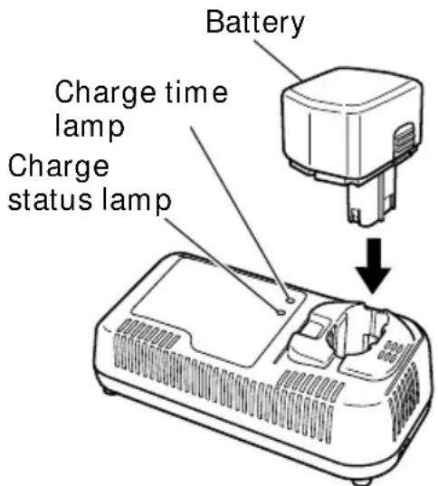
Fig. 7
- Insert the plug of battery charger into the receptacle.
When the plug of battery charger has been inserted into the receptacle, the charge status lamp will blink in red. (At 1-second intervals)
natural_image
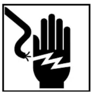
Black and white illustration of a hand with a lightning bolt symbol (no text or numbers)WARNING:
Do not use the electrical cord if damaged. Have it repaired immediately.
- Insert the battery to the battery charger.
Insert the battery into the battery charger as shown in Fig. 7. Make sure it contacts the bottom of the battery charger.
- Charging.
When the battery is connected to the battery charger, charging starts, and the charge time lamp lights red, orange, or green according to the remaining charging time. (See Table 4)
(1) Lamp indications
This charger is equipped with a charge time lamp that indicates remaining charging time, and a charge status lamp that indicates battery status as shown in Table 4.
(a) Charging time
After charging commences, the charge time lamp lights red indicating 30 minutes, orange indicating 20 minutes, and green indicating 5 minutes until completion. When the battery is fully charged, the charge status lamp lights green, and the buzzer sounds continuously for 6 seconds.
(b) Overheat standby
When the battery is overheated, it cannot be charged, and the charge time lamp flashes red (in 0.6 second intervals). Leave the battery inserted in the charger, and charging will commence when the battery cools down.
(c) Charging impossible
When there is a malfunction with the battery or charger, the charge status lamp flashes orange rapidly (in 0.2 second intervals), and the buzzer sounds intermittently for 5 seconds.
Table 4 Lamp indications
| Lamp indications Status lamp | ||||
| Charge time Charge lamp(red/Charg orange/green) | Charging time Lights 30 minutes red | Lights continuously | 30 minutes until charging complete. | |
| Charging time Lights Lights 20 minutes orange | lights continuously | 20 minutes until charging complete. | ||
| Charging time Lights Lights 5 minutes green | lights continuously | 5 minutes until charging complete. | ||
| Overheat standby | Blinks red | Lights for 0.3 seconds, off 0.3 seconds | Battery overheated. Unable to charge.(Charging will commence when battery cools.) | |
| Charge status lamp(red/orange/green) | Before charging | Blinks red receptacle | Lights for 0.5 seconds, off 0.5 seconds | Power cord is connected to |
| Charging complete | Lights Lights green | continuously | ||
| Charging Blinks impossible orange | ■ ■ ■ ■ ■ ■ | Lights for 0.1 seconds, off 0.1 seconds | Battery or charger malfunction. | |
(2) Regarding the temperature of the rechargeable battery
The temperatures for rechargeable batteries are as shown in the table below, and batteries that have become hot should be cooled for a while before being recharged.
Table 5 Recharging of batteries that have become hot
| Rechargeable battery Tem | peratures at which the battery can be recharged |
| EB1414S | 23°F — 131°F (-5°C — 55°C) |
4. Disconnect battery charger from the receptacle.

CAUTION:
Do not pull the plug out of the receptacle by pulling on the cord.
Make sure to grasp the plug when removing from receptacle to avoid damaging cord.
5. Remove the battery from the battery charger.
Supporting the battery charger with hand, pull out the battery from the battery charger.

CAUTION:
- Repair is required if the receptacle is not secured properly or the power cord does not stay in the receptacle. Consult your electrician. Using the charger in this condition may lead to fire.
- If the charge status lamp is blinking orange rapidly (in 0.2 second intervals) and the buzzer sounds intermittently for 5 seconds, check that the hole for connecting the battery is not obstructed. Remove any obstructions. If no obstructions are found, the battery or charger may be malfunctioned. Return both to your place of purchase.
-
If the charge time lamp does not light when the power cord is connected to the receptacle, disconnect the power cord, and check that the battery is attached correctly.
-
The battery retains heat when used or left for prolonged periods in direct sunlight. In this state, the charge time lamp flashes red, and the battery cannot be charged immediately. Leave the battery inserted in the charger, and charging will commence when the battery cools down.
- If the lamp goes out while charging, disconnect the power cord, and leave for 3 to 5 minutes before reconnecting. If the problem persists, call for repairs.
- Leave 5 minutes between charging batteries as the charger may overheat leading to malfunction.
- The battery life is finished if it can only be used for short periods even when fully charged. Purchase a new battery. Continuing to use a depleted battery may cause the charger to malfunction.
NOTE:
○Charging times may be longer depending on the surrounding temperature and battery conditions.
○Charge time lamp indications are only a guide, and may vary depending on the surrounding temperature and battery conditions.
○Remove the battery from the charger when not in use.
Revitalizing the battery (trickle recharge)
A new battery or a battery that has not been used for extensive periods may not charge completely due to internal chemicals being inert.
Leave the battery inserted in the charger for 8 to 12 hours after charging is complete. The charger automatically “revitalizes” the battery by trickle recharging.
How to make the batteries perform longer
(1) Recharge the batteries before they become completely exhausted.
When you feel that the power of the tool becomes weaker, stop using the tool and recharge its battery. If you continue to use the tool and exhaust the electric current, the battery may be damaged and its life will become shorter.
(2) Avoid recharging at high temperatures.
A rechargeable battery will be hot immediately after use. If such a battery is recharged immediately after use, its internal chemical substance will deteriorate, and the battery life will be shortened. Leave the battery and recharge it after it has cooled for a while.
NOTE: Before plugging into the receptacle, make sure the following points.
○The power source voltage is stated on the nameplate.
○The cord is not damaged.

WARNING: Do not charge at voltage higher than indicated on the nameplate.
If charged at voltage higher than indicated on the nameplate, the charger will burn up.
- Insert the plug of battery charger into the receptacle

natural_image
Black and white illustration of a hand with a lightning bolt symbol (no text or numbers)
WARNING: Do not use the electrical cord if damaged. Have it repaired immediately.
- Insert the battery to the battery charger Insert the battery into the battery charger as shown in Fig. 8. Make sure it contacts the bottom of the battery charger.

Fig. 8
3. Charging
○When the battery is connected to the battery charger, charging will commence and the pilot lamp will light on.
NOTE: If the pilot lamp dose not light, pull out the plug from the receptacle and check if the battery is properly mounted.
○In approx. 60 min., when the battery is fully charged, the pilot lamp will go out.
NOTE: The battery charging time becomes longer when a temperature is low or the voltage of the power source is too low.
When the pilot lamp does not go off even if more than four hour has passed after start of the charging, stop the charging and contact your HITACHI AUTHORIZED SERVICE CENTER.
○Regarding the temperature of the rechargeable battery.
The temperatures for rechargeable batteries are as shown in the table below, and batteries that have become hot should be cooled for a while before being recharged.
Table 6
| Rechargeable battery Tem | peratures at which the battery can be recharged |
| EB1414S | 50°F — 104°F (10°C — 40°C) |
BEFORE USE
- Check the work area environment
Check the work area to make sure that it is clear of debris and clutter.
Clear the area of unnecessary personnel. Ensure that lighting and ventilation is adequate.
- Check if saw blade is tightened
While the saw blade is tightened securely for immediate use when it is assembled at the factory, be sure to check it out again for caution's sake. A bolt can be tightened when it is turned clockwise. Use the provided box wrench to check it out.
For further details, refer to the item of [MOUNTING AND DISMOUNTING THE SAW BLADE] on Page 26.
- Check if wing nut is tightened
If the wing nut to adjust cutting depth (Fig. 10) is loose, injury can result. Make sure that it is tightened securely.
- Check performance of lower guard

WARNING: Make absolutely sure that the lower guard is not fixed. Also, check and see if it can move smoothly. If the saw blade is kept exposed, injury can result.
The lower guard (refer to Fig. 3) serves to protect your body from coming into contact with the saw blade. Make absolutely certain that the cover smoothly performs to cover the saw blade. If the lower guard should not move smoothly, never use it without repairing it.
In such a case, get in touch with the store where you bought the circular saw or the HITACHI AUTHORIZED SERVICE CENTER for necessary repair.
- Check battery insertion

WARNING: If the battery is inserted while the power switch is in the ON position, the power tool will start operating immediately, inviting serious accident.

CAUTION: Until the battery locks in place with a little click, if not, it may accidentally fall out of the tool causing injury to you or someone around you.
- Check for proper operation of the brake
This circular saw features an electric brake that functions when the switch is released. Before using the circular saw, ensure that the electric brake functions properly. If it does not, bring the tool to a HITACHI AUTHORIZED SERVICE CENTER.
- Prepare a wooden work bench (Fig. 9) Since the saw blade will extend beyond the lower surface of the lumber, place the lumber on a work bench when cutting. If a square block is utilized as a work bench, select level ground to ensure it is properly stabilized. An unstable work bench will result in hazardous operation.

CAUTION:
To avoid possible accident, always ensure that the portion of lumber remaining after cutting is securely anchored or held in position.
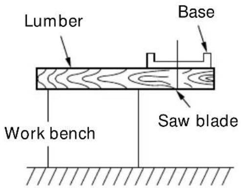
Fig. 9
ADJUSTING THE SAW PRIOR TO USE
- Adjusting the cutting depth (Fig. 10)

WARNING: If the wing-nut is loose, injury can result. Tighten it securely after adjustment.
To adjust cutting depth, loosen the Wing-nut and, while holding the base with one hand, move the main body up and down to obtain the prescribed cutting depth. After adjusting to the prescribed cutting depth, tighten the Wing-nut securely.
- Adjusting the angle of inclination

WARNING: If the wing-nut is loose, injury can result. Tighten it securely after adjustment.

Fig. 10
As shown in Fig. 11 by loosening the wing-bolt on the inclined gauge, the saw blade may be inclined to a maximum angle of 50^ in relation to the base. Always insure that the wing-bolt is thoroughly tightened after making the desired adjustment.
NOTE: Values of the inclined gauge provided on the base merely serve as a rough guideline. For cutting operation at an inclined posture, use the circular saw after adjusting the angle between the base and the saw blade with a protractor, etc.
3. Regulating the guide (Fig. 12)
The cutting position can be regulated by moving the guide to the left or right after loosening its knob-bolt. The guide may be mounted on either the right or left side of the tool.

Fig. 11

Fig. 12
OPERAION
WARNING:
- Never touch the moving parts.
- Never operate the circular saw with the saw blade turned upward or to the side.
- Do not fix and secure the switch lock. Besides, keep your finger off the switch trigger when the circular saw is being carried around. Otherwise, the main body switch can be inadvertently turned ON, resulting in unexpected accidents.
- Keep the light ON during cutting operation only. If it is lit ON in other cases, the main body switch can be inadvertently turned ON, resulting in unexpected accidents.
CAUTION:
- Don't remove circular saw from workpiece during a cut while the saw blade is moving.
- Pull out the battery after completing operation.
NOTE:
Take care not to lock the motor. If the motor is locked, immediately turn the power off. If the motor is locked for a while, the motor or battery may be burnt.
1. Operation of switch (Switch trigger and light switch)
For safe operation of the machine, a "switch lock" is provided on the side of a handle.
If the “switch lock” is pulled in a state where it is pressed in the direction of the arrow mark, the main switch can be turned ON.
(3) If you release the switch trigger, you can turn OFF the switch and the "switch lock" returns to the original position automatically and the light turns OFF too.
(1) Switch lock is used as the "light switch". If the "switch lock (light switch)" is pulled in a state, the light is turned ON.
(2) After the switch is turned ON, even when you release your hand from the switch lock, the body continues running and the light continues being turned ON as long as you keep on pulling the switch trigger.
2. Working performance per single charge (Reference data)
○ Cutting capability differs according to the condition of lumber, type of saw blade, ambient temperature, battery characteristics, etc.
| Wood | Capacity |
| EB1414S | |
| 2 × 8 (Spruce-Pine-Fir) 50 (cuts) | |
| Concreteform plywood (1/2” (12 mm) t) 67 ft (20 m) | |
To improve working efficiency per single charge,
○Minimize operation (no-load operation) other than cutting;
○Avoid any unreasonably forced pressure to the motor during cutting operation by twisting or pressing the circular saw forcibly;
○Avoid any use of dull saw blade.

Fig. 13
3. Cutting procedures
CAUTION:
- Recheck that the saw blade is securely clamped.
- Confirm that the wing-nut for adjusting the slot depth, the wing-bolt for adjusting the angle of inclination.
(1) Place the base on the material, then align the premarked line and the saw blade with the notch at the front of the base (Fig. 14).
(2) When the base is not inclined, use the large notch (Fig. 14, Fig. 15). If the base is inclined (45 degrees), use the small notch (Fig. 14, Fig. 16).
NOTE: When using the saw at the inclination of 45 degrees, use both the marks of on the bevel plate and [45] on the inclined gauge of the base (Fig. 17). What's more, if it is absolutely essential to use the saw at a precise angle, make adjustment using a protractor, etc.
(3) Ensure that the switch is turned to the ON position before the saw blade comes in contact with the lumber. The switch is turned ON when the trigger is squeezed; and OFF when the trigger is released. Moving the saw straight at a constant speed will produce optimum cutting.
CAUTION:
- Before starting to saw, ensure that the saw blade has reached full speed revolution.
- Should the saw blade be stopped or made an abnormal noise during operation, turn off the switch immediately.
- When finished with a job, pull out the battery from the main body.

Fig. 14 (Top View)

Fig. 15 Not inclined

Fig. 16
- Twisting and forcibly pressing the saw during cutting can result in unreasonable pressure on the motor, so try to go straight quietly.
- In the situation where the circular saw is continuously operated while replacing the battery with stocked spare batteries one after another, the motor tends to overheat. Therefore, whenever the housing becomes hot, give the saw a break for a while.
- Avoid cutting operation in a state where the base bottom is afloat from the material being cut. Otherwise, the motor can get locked.

Fig. 17
MOUNTING AND DISMOUNTING THE SAW BLADE
CAUTION:
To avoid serious accident, ensure the switch is in the OFF position, and pull out the battery.
- Dismounting the saw blade
(1) Set the cutting volume at maximum, and place the Circular Saw as shown in Fig. 18.
(2) Depress the lock lever, lock the spindle, and remove the left-hand bolt and washer (B1) with the box wrench.
(3) While holding the lower guard lever to keep the lower guard fully retracted into the saw cover, remove the saw blade (Fig. 19).
- Mounting the Saw Blade (Fig. 20)
WARNING:
If the left-hand bolt is worked using other tools than the provided box wrench, excessive tightening and insufficient tightening may take place, resulting in injury.
○Take procedures here that are contrary to the detaching procedures.

Fig. 18
NOTE:
●Thoroughly remove any sawdust which has accumulated on the spindle, bolt and washers.
●To assure proper rotation direction of the saw blade, the arrow direction on the saw blade must coincide with the arrow direction on the saw cover.
●Using the fingers, tighten the left-hand bolt retaining the saw blade as much as possible. Then depress the lock lever, lock the spindle, and thoroughly tighten the left-hand bolt.
CAUTION:
After mounting the saw blade, reconfirm that the lock lever is firmly secured in the prescribed position.
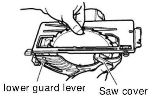
Fig. 19
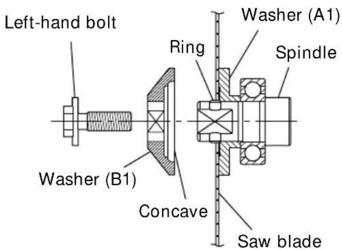
Fig. 20
REPLACING LIGHT BULB (ONLY MODEL WITH LIGHT)
WARNING:
- Make absolutely sure that the battery is removed from the main body before replacing the light bulb.
- Immediately after the light is turned OFF, the bulb retains high temperature. Make sure to cool down the light bulb thoroughly before replacing it so as to prevent burns.
CAUTION:
When replacing the light bulb, check the shape of base as well as the rating (12 V, 5 W), and then carry out perfect mounting. Otherwise, the light bulb can come off and/or cause overheat.
1. Detaching light bulb
(1) Remove the convex part of the light cover from the concave part of the housing, and then pull out the light cover in the arrow-marked direction as shown in Fig. 21.
(2) Push the back of the socket, and remove the socket and the light bulb together from the housing (Fig. 22).
(3) Remove the light bulb from the socket (Fig. 23).
2. Attaching light bulb
Take procedures here that are contrary to the detaching procedures.
NOTE:
●When attaching the light bulb to the socket, insert the light bulb until it lightly bumps against the socket.
- When attaching the socket to the housing, align the socket with the hole of housing while watching the back of the socket shown in Fig. 23, and insert the socket until it lightly bumps against the housing.

Fig. 21
Back of the socket
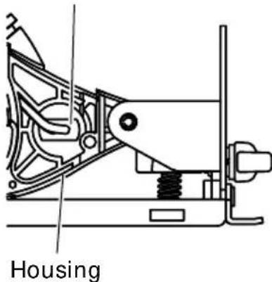
Fig. 22

Fig. 23 (Top View)
MAINTENANCE AND INSPECTION
CAUTION: Pull out battery before doing any inspection or maintenance.
1. Inspecting the saw blade
Since use of a dull saw blade will degrade efficiency and cause possible motor malfunction, sharpen or replace the saw blade as soon as abrasion is noted.
CAUTION:
If a dull saw blade is used, reactive force is increased during cutting operation. Avoid the use of the dull saw blade without repair.
2. Check the mounting screws
Loose mounting screws are dangerous. Regularly inspect them and make sure they are tight.
CAUTION: Using this power tool with loosen, screws is extremely dangerous.
3. Performance checkup and maintenance of lower guard
Keep the lower guard in good shape for smooth performance at all times. Be sure to make prompt repair in case of any malfunction.
4. Adjusting the base and saw blade to maintain perpendicularity
The angle between the base and the saw blade has been adjusted to 90^ , however should this perpendicularity belost for some reason, adjust in the following manner.
(1) Turn the base face up (Fig. 24) and loosen the wing-bolt.
(2) Apply a square to the base and the saw blade and, turning the slotted set screw with a slotted-head screwdriver, shift the position of the base to produce the desired right angle.
5. Check for dust
Dust may be removed with a clean rag or a cloth dampened with soapy water. Do not use bleach, chlorine, gasoline or thinner, for they may damage the plastics.

Fig. 24
6. Disposal of the exhausted battery
WARNING: Do not dispose of the exhausted battery. The battery must explode if it is incinerated. The product that you have purchased contains a rechargeable battery. The battery is recyclable. At the end of it's useful life, under various state and local laws, it may be illegal to dispose of this battery into the municipal waste stream. Check with your local solid waste officials for details in your area for recycling options or proper disposal.
7. Storage
Storing in a place below 104^ F ( 40^ C) and out of the reach of children.
8. Service and repairs
All quality power tools will eventually require servicing or replacement of parts because of wear from normal use. To assure that only genuine replacement parts must be used, all service and repairs must be performed by a HITACHI AUTHORIZED SERVICE CENTER, ONLY.
9. Service parts list

CAUTION: Repair, modification and inspection of Hitachi Power Tools must be carried out by a HITACHI AUTHORIZED SERVICE CENTER.
This Parts List will be helpful if presented with the tool to the HITACHI AUTHORIZED SERVICE CENTER when requesting repair or other maintenance. In the operation and maintenance of power tools, the safety regulations and standards prescribed in each country must be observed.
MODIFICATIONS:
Hitachi Power Tools are constantly being improved and modified to incorporate the latest technological advancements.
Accordingly, some parts may be changed without prior notice.
ACCESSORIES

WARNING: ALWAYS use Only authorized HITACHI replacement parts and accessories. NEVER use replacement parts or accessories which are not intended for use with this tool. Contact HITACHI if you are not sure whether it is safe to use a particular replacement part or accessory with your tool.
The use of any other attachment or accessory can be dangerous and could cause injury or mechanical damage.
NOTE:
Accessories are subject to change without any obligation on the part of the HITACHI.
STANDARD ACCESSORIES
| C14DMR |  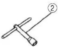 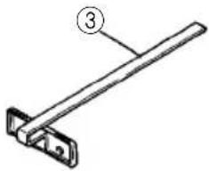 | ||
   | |||
| 1Saw Blade (mounted on tool).... 1 | |||
| External Diam. Hole Diam. Code No. | |||
| 6-1/2" (165 mm) | 5/8" (15.9 mm) | 324293 | |
| 2Box Wrench (Code No.940543).... 13 Guide (Code No.302756).... 14Battery (EB1414S).... 15Battery Charger (UC18YG).... 16 Plastic Case.... 1 | |||
OPTIONAL ACCESSORIES.....sold separately
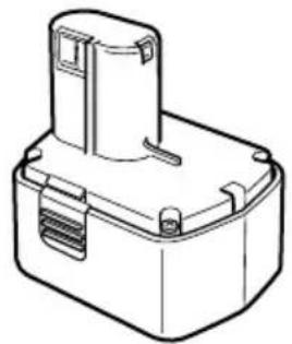
- Battery (EB1414S)
natural_image
Line drawing of a battery pack with no text or symbols- Saw Blade Use ... Cutting various types of wood.

natural_image
Simple curved line drawing with jagged edges (no text or symbols)| External Diam. D | Hole No. of am. teeth | Code No. | |
| 6-1/2" 5/8"(165 mm) | (15.9 mm) | 24 Pieces | 324293 |
NOTE
Specifications are subject to change without any obligation on the part of the HITACHI.
INFORMATIONS IMPORTANTES DE SÉCURITÉ
natural_image
Line drawing of a mechanical device mounted on a flat base (no text or symbols)
natural_image
Line drawing of a table with a sewing machine and two chairs, crossed by two gray X-shaped markers (no text or symbols)natural_image
Black and white icon of a hand with a lightning bolt symbol, no text or numbers presentnatural_image
Black and white illustration of a hand with a lightning bolt symbol (no text or numbers)⚠ AVERTISSEMENT :
(c) Charge impossible
natural_image
Black and white illustration of a hand with a lightning bolt symbol (no text or numbers)
AVERTISSEMENT:
natural_image
Technical line drawing of a mechanical assembly with no visible text or symbolsLogement
Fig. 22
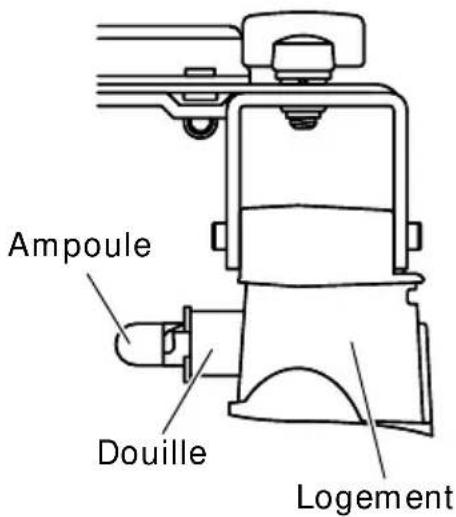
Fig. 23
ENTRETIEN ET INSPECTION

natural_image
Technical line drawing of a rectangular electronic component with a cylindrical top and mounting base (no text or symbols)natural_image
Simple line drawing of a curved, jagged edge with no text or symbols| Dia. Dia. No. de No. de externe d'orifice dents code. | |||
| 6-1/2" 5/8"(165 mm) (15.9 mm) | 24 Pièces | 324293 |
REMARQUE:
natural_image
Two technical diagrams showing a flat table and a table with mechanical components, one marked with a cross (no text or symbols present)natural_image
Black and white illustration of a hand with a lightning bolt symbol (no text or numbers)natural_image
Black and white icon of a hand with a lightning bolt symbol, no text or numbers presentADVERTENCIA:
natural_image
Black and white illustration of a hand with a lightning bolt symbol (no text or numbers)
ADVERTENCIA:
natural_image
Line drawing of a rectangular electronic component with a cylindrical top and side slots (no text or symbols)natural_image
Simple curved line drawing with jagged edges, no text or symbols presentnatural_image
Simple line drawing of a quill pen in an inkwell (no text or symbols)
| Item No. | Part Name |
| 1 BOLT (W/WASHER) M7×17.5 | |
| 2 WASHER (B1) | |
| 3 TCT SAW BLADE 165MM-15.9 | |
| 4 RING D15.9/I.D14.5 | |
| 5 WASHER (A1) | |
| 6 SEAR LOCK FLAT HD. SCREW M3×12 | |
| 7 BEARING COVER | |
| 8 BALL BEARING 6002VVCMPS2L | |
| 9 LOWER GUARD | |
| 10 BUSHING | |
| 11 SEAL LOCK FLAT HD. SCREW M5×12 | |
| 12 BEARING HOLDER | |
| 13 GEAR | |
| 14 TAPPING SCREW (W/FLANGE) D5×50 | |
| 15 FLAT HD. SCREW M5×20 | |
| 16 CUSHION | |
| 17 HITACHI LABEL | |
| 18 SAW COVER | |
| 19 RETURN SPRING | |
| 20 LABEL (LC) | |
| 21 LIGHT COVER ASS'Y | |
| 22 NYLOCK BOLT (W/FLANGE) M4×12 | |
| 23 INNER COVER (B) | |
| 24 BALL BEARING 609VVC2PS2L | |
| 25 LOCK LEVER | |
| 26 SPECIAL BOLT M5 | |
| 27 INNER COVER (A) ASS'Y | |
| 28 MOTOR (B) | |
| 29 TAPPING SCREW D4×10 | |
| 30 SOCKET | |
| 31 LIGHT | |
| 32 TERMINAL (D) | |
| 33 NAMEPLATE | |
| 34 HOUSING | |
| 35 CAUTION PLATE | |
| 36 SPRING | |
| 37 WING BOLT (A) | |
| 38 SUPER LOCK WASHER M6 | |
| 39 BASE ASS'Y | |
| 40 KNOB BOLT | |
| 41 SPRING | |
| 42 SLOTTED HD. SET SCREW (SEAL LOCK) M6×6 | |
| 43 BOLT ASS'Y (SQUARE) M2×22 | |
| 44 WASHER M6 | |
| 45 ROLL PIN | |
| 46 TAPPING SCREW (W/FLANGE) D4×16 | |
| 47 HANDLE COVER | |
| 48 RESISTOR (A) | |
| Item No. | Part Name |
| 49 RESISTOR | |
| 50 CONNECTOR | |
| 51 INTERNAL WIRE | |
| 52 SWITCH | |
| 53 SPRING (F) | |
| 54 TERMINAL (A) | |
| 55 KNOB | |
| 56 HOLDER SPRING | |
| 57 TERMINAL | |
| 58 TERMINAL PIECE | |
| 59 TERMINAL | |
| 60 BATTERY | |
| 501 CHARGER | |
| 502 CASE | |
| 503 BOX WRENCH | |
| 504 GUIDE | |


Please contact HITACHI KOKI U.S.A. LTD. at 1-800-59-TOOLS (toll free), or HITACHI AUTHORIZED POWER TOOL SERVICE CENTER regarding COLLECTION.


Pour le RAMASSAGE, contacter HITACHI KOKI U.S.A. LTD. au 1-800-59-TOOLS (appel gratuit), ou UN SERVICE APRES-VENTE D'OUTILS ELECTRIQUE AGREE PAR HITACHI.


Minato-ku, Tokyo 108-6020, Japan
Distributed by

Hitachi Koki U.S.A., Ltd.
3950 Steve Reynolds Blvd.
Norcross, GA 30093

Hitachi Koki Canada Co.
6395 Kestrel Road
Mississauga ON L5T 1Z5
- SAFETY INSTRUCTIONS AND INSTRUCTION MANUAL
- WARNING
- INSTRUCTIONS DE SECURITE ET MODE D'EMPLOI
- ! AVERTISSEMENT
- TABLE DES MATIERES
- Français
- IMPORTANT SAFETY INFORMATION
- MEANINGS OF SIGNAL WORDS
- SAFETY
- GENERAL SAFETY RULES – FOR ALL BATTERY OPERATED TOOLS
- WARNING: Read and understand all instructions.
- SAVE THESE INSTRUCTIONS
- Work Area
- Electrical Safety
- Personal Safety
- Tool Use and Care
- Service
- WARNING:
- SPECIFIC SAFETY RULES
- Use right tool.
- Never use a power tool for applications other than those specified.
- Handle tool correctly.
- Definitions for symbols.
- Keep all screws, bolts and covers tightly in place.
- Do not use power tools if the plastic housing or handle is cracked.
- Blades and accessories must be securely mounted to the tool.
- Never use a tool which is defective or operating abnormally.
- Carefully handle power tools.
- Do not wipe plastic parts with solvent.
- IMPORTANT SAFETY INSTRUCTIONS FOR USE OF THE CORDLESS CIRCULAR SAW
- IMPORTANT SAFETY INSTRUCTIONS FOR BATTERY CHARGER
- IMPORTANT SAFETY INSTRUCTIONS FOR USE OF THE BATTERY AND BATTERY CHARGER
- WARNING: Improper use of the battery or battery charger can lead to serious injury. To avoid these injuries:
- AND
- MAKE THEM AVAILABLE TO
- OTHER USERS
- OWNERS OF THIS TOOL!
- FUNCTIONAL DESCRIPTION
- MODEL
- NAME OF PARTS
- Battery Charger
- SPECIFICATIONS
- Cordless Circular Saw (C14DMR)
- ASSEMBLY AND OPERATION
- APPLICATIONS
- REMOVAL AND INSTALLATION METHOD OF BATTERY
- CHARGING METHOD
- WARNING: Do not use the electrical cord if damaged. Have it repaired immediately.
- Insert the battery to the battery charger
- CAUTION:
- Charging
- Pilot lamp indication
- Regarding the temperature of the rechargeable battery
- Disconnect battery charger from the receptacle
- Remove the battery from the battery charger
- Regarding electric discharge in case of new batteries, etc.
- How to make the batteries perform longer.
- Disconnect battery charger from the receptacle.
- Remove the battery from the battery charger.
- NOTE:
- Revitalizing the battery (trickle recharge)
- How to make the batteries perform longer
- BEFORE USE
- ADJUSTING THE SAW PRIOR TO USE
- Regulating the guide (Fig. 12)
- OPERAION
- Operation of switch (Switch trigger and light switch)
- Working performance per single charge (Reference data)
- Cutting procedures
- MOUNTING AND DISMOUNTING THE SAW BLADE
- REPLACING LIGHT BULB (ONLY MODEL WITH LIGHT)
- Detaching light bulb
- Attaching light bulb
- MAINTENANCE AND INSPECTION
- CAUTION: Pull out battery before doing any inspection or maintenance.
- Inspecting the saw blade
- Check the mounting screws
- CAUTION: Using this power tool with loosen, screws is extremely dangerous.
- Performance checkup and maintenance of lower guard
- Adjusting the base and saw blade to maintain perpendicularity
- Check for dust
- Disposal of the exhausted battery
- Storage
- Service and repairs
- Service parts list
- MODIFICATIONS:
- ACCESSORIES
- STANDARD ACCESSORIES
- OPTIONAL ACCESSORIES.....sold separately
- NOTE
- INFORMATIONS IMPORTANTES DE SÉCURITÉ
- ⚠ AVERTISSEMENT :
- AVERTISSEMENT:
- ENTRETIEN ET INSPECTION
- REMARQUE:
- ADVERTENCIA:
- Hitachi Koki U.S.A., Ltd.
- Hitachi Koki Canada Co.
Brand : HITACHI
Model : C 14DMR
Category : Saw